EP1662239A2 - Elektronisches Fieberthermometer - Google Patents
Elektronisches Fieberthermometer Download PDFInfo
- Publication number
- EP1662239A2 EP1662239A2 EP05022807A EP05022807A EP1662239A2 EP 1662239 A2 EP1662239 A2 EP 1662239A2 EP 05022807 A EP05022807 A EP 05022807A EP 05022807 A EP05022807 A EP 05022807A EP 1662239 A2 EP1662239 A2 EP 1662239A2
- Authority
- EP
- European Patent Office
- Prior art keywords
- power
- power switch
- electronic clinical
- clinical thermometer
- turning
- Prior art date
- Legal status (The legal status is an assumption and is not a legal conclusion. Google has not performed a legal analysis and makes no representation as to the accuracy of the status listed.)
- Withdrawn
Links
- 238000000034 method Methods 0.000 abstract description 22
- 230000036760 body temperature Effects 0.000 description 24
- 238000005259 measurement Methods 0.000 description 20
- 238000009529 body temperature measurement Methods 0.000 description 8
- 238000010586 diagram Methods 0.000 description 2
- 101000661807 Homo sapiens Suppressor of tumorigenicity 14 protein Proteins 0.000 description 1
- 238000012986 modification Methods 0.000 description 1
- 230000004048 modification Effects 0.000 description 1
- 229920003023 plastic Polymers 0.000 description 1
- 239000004033 plastic Substances 0.000 description 1
- 230000002265 prevention Effects 0.000 description 1
- 230000005855 radiation Effects 0.000 description 1
- 229910001220 stainless steel Inorganic materials 0.000 description 1
- 239000010935 stainless steel Substances 0.000 description 1
- 210000003454 tympanic membrane Anatomy 0.000 description 1
- 230000000007 visual effect Effects 0.000 description 1
Images



Classifications
-
- G—PHYSICS
- G01—MEASURING; TESTING
- G01K—MEASURING TEMPERATURE; MEASURING QUANTITY OF HEAT; THERMALLY-SENSITIVE ELEMENTS NOT OTHERWISE PROVIDED FOR
- G01K13/00—Thermometers specially adapted for specific purposes
- G01K13/20—Clinical contact thermometers for use with humans or animals
-
- A—HUMAN NECESSITIES
- A61—MEDICAL OR VETERINARY SCIENCE; HYGIENE
- A61B—DIAGNOSIS; SURGERY; IDENTIFICATION
- A61B5/00—Measuring for diagnostic purposes; Identification of persons
- A61B5/01—Measuring temperature of body parts ; Diagnostic temperature sensing, e.g. for malignant or inflamed tissue
-
- G—PHYSICS
- G01—MEASURING; TESTING
- G01K—MEASURING TEMPERATURE; MEASURING QUANTITY OF HEAT; THERMALLY-SENSITIVE ELEMENTS NOT OTHERWISE PROVIDED FOR
- G01K2215/00—Details concerning sensor power supply
Definitions
- the present invention relates to an electronic clinical thermometer, more particularly to prevention of misoperation during measurement.
- a general contact type electronic clinical thermometer comprises a slender main body shaped like a pen, a temperature sensing unit provided at the tip of the main body, a display unit for showing the result of measurement provided at a side of the main body, a power switch provided in the rear part or side of the main body, and a control unit for executing measurement and arithmetic processing built in the main body.
- the most popular measuring area is beneath the armpit, and the user inserts the electronic clinical thermometer beneath the armpit inside the clothes, and holds for scores of seconds to several minutes to measure.
- the user must hold the electronic clinical thermometer beneath the armpit in contact at a position not seen from above the clothes, and in particular children tend to change the position during measurement, happening to press the power switch by mistake to cut off the power.
- the electronic clinical thermometer has no switch to be manipulated by the user, in which the electronic clinical thermometer having a built-in magnet lead switch is stored in an electronic clinical thermometer case having a magnet for actuating the magnet lead switch (refer to, for example, Japanese Utility Model Application Publication No. 7-44986).
- the invention is based on the problems of these prior arts, and it is an obj ect thereof to prevent power turn-off by misoperation during measurement of body temperature in unseen state without requiring complicated structure.
- An electronic clinical thermometer in one aspect of the invention comprises a power switch manipulated by the user to turn off the power from power-on state, and a control unit for turning off the power according to the manipulation of the power switch, in which the control unit turns off the power when it is judged that the power switch is manipulated in a predetermined pattern for turning off the power.
- the power switch also serves as manipulation switch for turning on the power by the user, and the manipulation pattern for turning on the power is a pattern different from a predetermined pattern for turning off the power.
- the predetermined pattern for turning off the power is to press the power switch continuously no less than a specified time.
- it further comprises an alarm unit for issuing an alarm sound
- the control unit drives and controls the alarm unit for issuing an alarm sound and turns off the power when it is judged that the power switch is pressed continuously no less than a specified time as predetermined pattern for turning off the power.
- the predetermined pattern for turning off the power is to press the power switch continuously no less than a first specified time and within a second specified time.
- the control unit drives and controls the alarm unit for issuing an alarm sound when it is judged that the power switch is pressed continuously no less than a first specified time as predetermined pattern for turning off the power, and turns off the power when it is judged that the power switch is released within a second specified time after issue of the alarm sound.
- the predetermined pattern for turning off the power is to press the power switch by a specified number of times within a specified time.
- the invention by turning off the power only when the power switch is manipulated in a predetermined characteristic manipulation pattern, it is possible to prevent power interruption during body temperature measurement due to accidental contact with the power switch and the like. By noticing by the alarm sound when the predetermined manipulation pattern is securely executed, the user can manipulate securely for turning off the power.
- FIG. 1 is an outline drawing of electronic clinical thermometer in an embodiment of the invention, FIG. 1A is a top view, and FIG. 1B is a front view;
- FIG. 1 shows an outline structure of electronic clinical thermometer in the present embodiment.
- FIG. 1A is a top view of the electronic clinical thermometer and
- FIG. 1B is a front view thereof.
- the electronic clinical thermometer 1 of the embodiment has a proper shape and size for contacting with the measuring area such as beneath the armpit of the user.
- the electronic clinical thermometer 1 comprises a temperature sensing unit 3, a display unit 4, and a power switch manipulation unit 5, which are provided in a main body 2.
- the main body 2 is made of plastics, having a slender shape in the lower part to be inserted easily by the user beneath the armpit and so on, and a wide rectangular shape in the upper part for displaying the result of measurement and so on largely and realizing an excellent visual recognition.
- the temperature sensing unit 3 is made of stainless steel, and is provided at the lower end of the main body 2, and a thermistor (described below) is incorporated inside as temperature sensing element.
- the display unit 4 is to show the result of measurement of body temperature or state of operation and so on, and it is provided at the upper front side of the main body 2.
- the power switch manipulation unit 5 is for manipulating the power switch (described below) built in the main body 2, and it is provided at the upper end of the main body 2.
- FIG. 2 shows function block diagram of electronic clinical thermometer of the embodiment.
- the electronic clinical thermometer 1 of the embodiment has a processing circuit incorporated in the inside of the main body 2.
- the processing circuit is built, for example, in the temperature sensing unit 3, and includes a thermistor 12 for converting the user's body temperature into an analog electrical signal, an A/D converter 13 for converting the analog electrical signal from the thermistor 12 into a digital signal, a CPU 11 as control unit for receiving the digital signal from the A/D converter 13 and on/off signal from the power switch 15, and performing arithmetic operations for measuring the body temperature and turning on or off the power, an LCD 14 as a display unit for showing the result of body temperature measurement or state of operation, a power switch 15 for receiving power on/off command, a buzzer 16 as alarm unit for issuing an alarm sound, and a battery 17 as power source.
- Body temperature measuring operation of processing circuit of the electronic clinical thermometer 1 of the embodiment is realized by a known art, and is executed, for example, as follows.
- the thermistor 12 in the temperature sensing unit 3 converts the user' s body temperature information into an analog electrical signal.
- the analog electrical signal from the thermistor 12 is converted into a digital signal by the A/D converter 13, and put into the CPU 11.
- the CPU 11 judges that body temperature measurement is started, displays that measurement is in process in the LCD 14. Also, on the basis of the entered digital signal, the CPU 11 calculates the body temperature of the user. When calculation of body temperature is over, the CPU 11 notices completion of measurement by the LCD 14 and buzzer 16, and displays the result of measurement of body temperature in the LCD 14. The user recognizes completion of body temperature measurement by the alarm sound of the buzzer 16, then takes out the electronic clinical thermometer 1 from the measuring area, and confirms the result of measurement displayed in the LCD 14, and presses down the power switch manipulation unit 5. When the power switch 15 is manipulated, the CPU 11 turns off the power of the processing circuit, and the measuring operation is completed.
- the electronic clinical thermometer 1 When the user measures the body temperature beneath the armpit, generally, without taking off the clothes, the electronic clinical thermometer 1 is inserted inside of the clothes, until the temperature sensing unit 3 touches beneath the armpit. This state must be maintained for scores of seconds to several minutes to measure the body temperature. The user maintains the measuring position by pressing the electronic clinical thermometer 1 beneath the armpit, or supporting the electronic clinical thermometer 1 by hand from above the clothes. However, children often change the position or move the supporting hand, and the power switch manipulation unit 5 may be pressed by mistake.
- the CPU 11 is designed to execute the power turn-off process only when it is judged that the power switch 15 is manipulated in a predetermined pattern for turning off the power from the turn-on state.
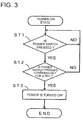
- FIG. 3 is a flowchart for explaining the power turn-off process of the electronic clinical thermometer 1 of the embodiment.
- step 1 the CPU 11 monitors whether the power switch 15 is pressed or not (step 1, hereinafter referred to as ST1): When it is judged that the power switch 15 is not pressed (NO at ST1) , the CPU 11 returns to ST1, and continues to monitor whether the power switch 15 is pressed or not.
- step 2 the CPU 11 monitors whether the power switch 15 is pressed continuously for no less than 2 seconds or not (ST2) .
- ST2 the CPU 11 returns to ST1, and continues to monitor whether the power switch 15 is pressed or not.
- the CPU 11 starts the process of turning off the power of the processing circuit (ST3), and the process is terminated.
- the specified time for pressing the power switch 15 continuously at ST2 is no less than 2 seconds, and this duration is determined in consideration that power turn-of f process is not executed if the hand or other part of the body accidentally and momentarily touches the power switch operation unit 5, and that the operability is worsened by demanding the user to press the power switch manipulation unit 5 continuously longer than necessary. If this specified time is set preliminarily, however, it is not limited to 2 seconds.
- the power switch 15 is designed to be used not only when turning off the power of the processing circuit, but also when turning on.
- body temperature measurement is not started naturally, and the user can manipulate the power switch manipulation unit 5 while recognizing visually, and it may be designed to turn on the power only when the power switch 15 is merely pressed down.
- the manipulation pattern of the power switch manipulation unit 5 is more reliable.
- the CPU 11 when the CPU 11 starts the power turn-off process, it may drive the buzzer 16 to issue an alarm sound.
- the user easily recognizes that the power turn-on off operation is established, and if the power turn-off process is executed by misoperation during measurement of body temperature, interruption of body temperature measurement is readily recognized.
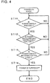
- FIG. 4 is a flowchart for explaining the power turn-off process of the electronic clinical thermometer 1 of this embodiment.
- the CPU 11 monitors whether the power switch 15 is pressed or not (ST11). When it is judged that the power switch 15 is not pressed (NO at ST11), the CPU 11 returns to ST11, and continues to monitor whether the power switch 15 is pressed or not. When it is judged that the power switch 15 is pressed (YES at ST11) , the CPU 11 monitors whether the power switch 15 is pressed continuously for no less than 2 seconds or not (ST12). When it is judged that the power switch 15 is not pressed continuously for no less than 2 seconds (NO at ST12) , the CPU 11 returns to ST11, and continues to monitor whether the power switch 15 is pressed or not.
- the CPU 11 monitors whether the power switch 15 is released from pressing within the next 3 seconds or not (ST13) . If it is judged that the power switch 15 is not released from pressing within the next 3 seconds (NO at ST13) , the CPU 11 returns to ST11, and continues to monitor whether the power switch 15 is pressed or not. When it is judged that the power switch 15 is released from pressing within the next 3 seconds (YES at ST13) , the CPU 11 executes the process of turning off the power of the processing circuit (ST14) , and the process is terminated.
- the power switch manipulation unit 5 if the power switch manipulation unit 5 is pressed for a long time accidentally while measuring the body temperature by the user by inserting the electronic clinical thermometer 1 beneath the armpit inside of the clothes, the power of the processing circuit is not turned off, and measurement of body temperature is not interrupted.
- the CPU 11 judges that the power switch 15 is pressed continuously for 2 seconds, it may drive the buzzer 16 to issue an alarm sound.
- the user easily recognizes the timing of releasing the power switch manipulation unit 5 from pressing for power turn-off operation, and power turn-off operation can be executed more securely.
- the power turn-off operation is not executed if the power switch 15 is pressed continuously over 3 seconds after issue of the alarm sound by the buzzer 16, so that interruption of body temperature measurement is prevented.
- the duration is not limited to the time specified in the embodiment.
- FIG. 5 is a flowchart for explaining the power turn-off process of the electronic clinical thermometer 1 of another embodiment.
- the CPU 11 monitors whether the power switch 15 is pressed or not (ST21). When it is judged that the power switch 15 is not pressed (NO at ST21), the CPU 11 returns to ST21, and continues to monitor whether the power switch 15 is pressed or not. When it is judged that the power switch 15 is pressed (YES at ST21), the CPU 11 monitors whether the power switch 15 is pressed three times within next 3 seconds or not (ST22). When it is judged that the power switch 15 is not pressed three times within next 3 seconds (NO at ST22) , the CPU 11 returns to ST21, and continues to monitor whether the power switch 15 is pressed or not. When it is judged that the power switch 15 is pressed three times within next 3 seconds (YES at ST22), the CPU 11 starts the process of turning-off the power of the processing circuit (ST23), and the process is terminated.
- the power switch manipulation unit 5 if the power switch manipulation unit 5 is touched accidentally while measuring the body temperature by the user by inserting the electronic clinical thermometer 1 beneath the armpit inside of the clothes, the power of the processing circuit is not turned off, and measurement of body temperature is not interrupted.
- the specified duration at ST22 and the specified number of times of pressing the power switch 15 are not limited to the time specified in the embodiment as far as they are preset.
- the CPU 11 when the CPU 11 starts power turn-off process, it may drive the buzzer 16 to issue an alarm sound.
- the user easily recognizes the establishment of power turn-off operation, and if power turn-off process is executed by misoperation during measurement of body temperature, interruption of body temperature measurement is readily recognized.
Landscapes
- Physics & Mathematics (AREA)
- Health & Medical Sciences (AREA)
- Life Sciences & Earth Sciences (AREA)
- General Physics & Mathematics (AREA)
- Medical Informatics (AREA)
- Animal Behavior & Ethology (AREA)
- Biomedical Technology (AREA)
- Heart & Thoracic Surgery (AREA)
- Pathology (AREA)
- Molecular Biology (AREA)
- Surgery (AREA)
- Engineering & Computer Science (AREA)
- General Health & Medical Sciences (AREA)
- Public Health (AREA)
- Veterinary Medicine (AREA)
- Biophysics (AREA)
- Measuring Temperature Or Quantity Of Heat (AREA)
- Measuring And Recording Apparatus For Diagnosis (AREA)
- Charge And Discharge Circuits For Batteries Or The Like (AREA)
Applications Claiming Priority (1)
| Application Number | Priority Date | Filing Date | Title |
|---|---|---|---|
| JP2004305676A JP2006118926A (ja) | 2004-10-20 | 2004-10-20 | 電子体温計 |
Publications (2)
| Publication Number | Publication Date |
|---|---|
| EP1662239A2 true EP1662239A2 (de) | 2006-05-31 |
| EP1662239A3 EP1662239A3 (de) | 2006-06-07 |
Family
ID=36097262
Family Applications (1)
| Application Number | Title | Priority Date | Filing Date |
|---|---|---|---|
| EP05022807A Withdrawn EP1662239A3 (de) | 2004-10-20 | 2005-10-19 | Elektronisches Fieberthermometer |
Country Status (7)
| Country | Link |
|---|---|
| US (1) | US20060082947A1 (de) |
| EP (1) | EP1662239A3 (de) |
| JP (1) | JP2006118926A (de) |
| KR (1) | KR20060054107A (de) |
| CN (1) | CN1763486A (de) |
| RU (1) | RU2005132300A (de) |
| TW (1) | TWI269871B (de) |
Families Citing this family (4)
| Publication number | Priority date | Publication date | Assignee | Title |
|---|---|---|---|---|
| JP5326378B2 (ja) * | 2008-06-25 | 2013-10-30 | オムロンヘルスケア株式会社 | 電子体温計 |
| US20120044011A1 (en) * | 2010-08-18 | 2012-02-23 | Nokia Corporation | Initiating forced shutdown of a device |
| WO2014049630A1 (ja) * | 2012-09-25 | 2014-04-03 | テルモ株式会社 | 電子体温計およびその制御方法 |
| CN109491287B (zh) * | 2018-11-08 | 2022-02-15 | 深圳迈睿智能科技有限公司 | 一种工作模式切换的方法、控制设备及微波感应器 |
Citations (2)
| Publication number | Priority date | Publication date | Assignee | Title |
|---|---|---|---|---|
| JPH0629790A (ja) | 1992-07-09 | 1994-02-04 | Fujitsu Ltd | ワンショットマルチバイブレータ |
| JPH0744986U (ja) | 1986-08-29 | 1995-12-05 | ドイチエ トムソン−ブラント ゲゼルシヤフト ミツト ベシユレンクテル ハフツング | ビデオレコーダ |
Family Cites Families (9)
| Publication number | Priority date | Publication date | Assignee | Title |
|---|---|---|---|---|
| US4426157A (en) * | 1982-01-29 | 1984-01-17 | Jetter Milton W | Clock alarm control system employing a push button alarm-deactivation switch which must be held depressed for a time period |
| GB8417415D0 (en) * | 1984-07-07 | 1984-08-30 | Plessey Co Plc | Switching apparatus |
| NL9220013A (nl) * | 1992-04-28 | 1993-11-16 | Ciberveu Sa | Klinische thermometer met digitale en gesproken weergave. |
| JP2970638B2 (ja) * | 1997-05-16 | 1999-11-02 | トヨタ自動車株式会社 | 移動体用機器遠隔制御装置 |
| US6079985A (en) * | 1997-10-23 | 2000-06-27 | Hasbro, Inc. | Programmable sound and music making device |
| KR100257879B1 (ko) * | 1998-02-19 | 2000-06-01 | 소호연 | 동물훈련장치 및 그 제어방법 |
| GB9925900D0 (en) * | 1999-11-03 | 1999-12-29 | Kindertec Ltd | Patient thermometer |
| US6442955B1 (en) * | 2001-03-06 | 2002-09-03 | Stuart Peter Oakner | Condensate overflow safety switch |
| US6661332B1 (en) * | 2003-03-10 | 2003-12-09 | Wei Hsu | Press-type varistor switch |
-
2004
- 2004-10-20 JP JP2004305676A patent/JP2006118926A/ja active Pending
-
2005
- 2005-10-19 KR KR1020050098492A patent/KR20060054107A/ko not_active Ceased
- 2005-10-19 RU RU2005132300/14A patent/RU2005132300A/ru not_active Application Discontinuation
- 2005-10-19 EP EP05022807A patent/EP1662239A3/de not_active Withdrawn
- 2005-10-19 US US11/255,517 patent/US20060082947A1/en not_active Abandoned
- 2005-10-20 TW TW094136641A patent/TWI269871B/zh not_active IP Right Cessation
- 2005-10-20 CN CNA2005101164368A patent/CN1763486A/zh active Pending
Patent Citations (2)
| Publication number | Priority date | Publication date | Assignee | Title |
|---|---|---|---|---|
| JPH0744986U (ja) | 1986-08-29 | 1995-12-05 | ドイチエ トムソン−ブラント ゲゼルシヤフト ミツト ベシユレンクテル ハフツング | ビデオレコーダ |
| JPH0629790A (ja) | 1992-07-09 | 1994-02-04 | Fujitsu Ltd | ワンショットマルチバイブレータ |
Also Published As
| Publication number | Publication date |
|---|---|
| RU2005132300A (ru) | 2007-04-27 |
| CN1763486A (zh) | 2006-04-26 |
| TW200628773A (en) | 2006-08-16 |
| TWI269871B (en) | 2007-01-01 |
| US20060082947A1 (en) | 2006-04-20 |
| KR20060054107A (ko) | 2006-05-22 |
| JP2006118926A (ja) | 2006-05-11 |
| EP1662239A3 (de) | 2006-06-07 |
Similar Documents
| Publication | Publication Date | Title |
|---|---|---|
| US20130310659A1 (en) | Blood pressure measuring device | |
| CN103976730B (zh) | 便携式生理参数测量仪及生理参数测量功能快速启动方法 | |
| US8644915B2 (en) | Handheld electrocardiographic device | |
| US20110216806A1 (en) | Ear thermometer with ear canal sensing device and measurement method thereof | |
| US20110223078A1 (en) | Device for measuring blood component | |
| US20070291820A1 (en) | Infrared clinical thermometer | |
| EP1752089B1 (de) | Elektronisches Blutdruckmessgerät und Datenverarbeitungsanlage | |
| US20040260190A1 (en) | Electrocardiograph and electrocardiograph control method | |
| KR101138955B1 (ko) | 이마형 적외선 체온계 | |
| JP6650534B2 (ja) | 複数の生体情報を測定する携帯用複合センサー装置および測定方法 | |
| US20060082947A1 (en) | Electronic clinical thermometer | |
| JP5326378B2 (ja) | 電子体温計 | |
| KR100533202B1 (ko) | 귓속형 체온계 | |
| JP5320111B2 (ja) | 血液成分測定装置 | |
| JP2006000481A (ja) | 携帯型生体信号測定装置 | |
| JP2012021886A (ja) | 女性体温計 | |
| JP2003024308A (ja) | 表示色切換機能付自己測定器 | |
| JP2012063304A (ja) | 電子体温計 | |
| JPH1132998A (ja) | 耳式体温計 | |
| CN116348007A (zh) | 具有柔性盖的气溶胶产生装置 | |
| JP4013960B2 (ja) | 耳式体温計 | |
| JP2000292251A (ja) | 検出器一体型振動計 | |
| JP2017194313A (ja) | 電子体温計 | |
| WO2012056628A1 (ja) | 生体試料測定装置 | |
| JP3726480B2 (ja) | 計測器およびその表示方法 |
Legal Events
| Date | Code | Title | Description |
|---|---|---|---|
| PUAI | Public reference made under article 153(3) epc to a published international application that has entered the european phase |
Free format text: ORIGINAL CODE: 0009012 |
|
| PUAL | Search report despatched |
Free format text: ORIGINAL CODE: 0009013 |
|
| AK | Designated contracting states |
Kind code of ref document: A2 Designated state(s): AT BE BG CH CY CZ DE DK EE ES FI FR GB GR HU IE IS IT LI LT LU LV MC NL PL PT RO SE SI SK TR |
|
| AX | Request for extension of the european patent |
Extension state: AL BA HR MK YU |
|
| AK | Designated contracting states |
Kind code of ref document: A3 Designated state(s): AT BE BG CH CY CZ DE DK EE ES FI FR GB GR HU IE IS IT LI LT LU LV MC NL PL PT RO SE SI SK TR |
|
| AX | Request for extension of the european patent |
Extension state: AL BA HR MK YU |
|
| AKX | Designation fees paid | ||
| STAA | Information on the status of an ep patent application or granted ep patent |
Free format text: STATUS: THE APPLICATION IS DEEMED TO BE WITHDRAWN |
|
| 18D | Application deemed to be withdrawn |
Effective date: 20061208 |
|
| REG | Reference to a national code |
Ref country code: DE Ref legal event code: 8566 |