EP1661867B1 - Artikel mit photokatalytische Beschichtung - Google Patents
Artikel mit photokatalytische Beschichtung Download PDFInfo
- Publication number
- EP1661867B1 EP1661867B1 EP05019047A EP05019047A EP1661867B1 EP 1661867 B1 EP1661867 B1 EP 1661867B1 EP 05019047 A EP05019047 A EP 05019047A EP 05019047 A EP05019047 A EP 05019047A EP 1661867 B1 EP1661867 B1 EP 1661867B1
- Authority
- EP
- European Patent Office
- Prior art keywords
- film
- photocatalytic
- article
- hydrophilic film
- area
- Prior art date
- Legal status (The legal status is an assumption and is not a legal conclusion. Google has not performed a legal analysis and makes no representation as to the accuracy of the status listed.)
- Ceased
Links
- 230000001699 photocatalysis Effects 0.000 title claims description 167
- 230000003746 surface roughness Effects 0.000 claims description 117
- 238000000034 method Methods 0.000 claims description 76
- VYPSYNLAJGMNEJ-UHFFFAOYSA-N Silicium dioxide Chemical compound O=[Si]=O VYPSYNLAJGMNEJ-UHFFFAOYSA-N 0.000 claims description 56
- GWEVSGVZZGPLCZ-UHFFFAOYSA-N Titan oxide Chemical compound O=[Ti]=O GWEVSGVZZGPLCZ-UHFFFAOYSA-N 0.000 claims description 52
- 238000005229 chemical vapour deposition Methods 0.000 claims description 43
- 239000000463 material Substances 0.000 claims description 31
- 229910052681 coesite Inorganic materials 0.000 claims description 28
- 229910052906 cristobalite Inorganic materials 0.000 claims description 28
- 239000000377 silicon dioxide Substances 0.000 claims description 28
- 229910052682 stishovite Inorganic materials 0.000 claims description 28
- 229910052905 tridymite Inorganic materials 0.000 claims description 28
- 239000011521 glass Substances 0.000 claims description 25
- -1 alumite Chemical compound 0.000 claims description 21
- 229920001721 polyimide Polymers 0.000 claims description 21
- 239000009719 polyimide resin Substances 0.000 claims description 16
- 238000005240 physical vapour deposition Methods 0.000 claims description 11
- XEEYBQQBJWHFJM-UHFFFAOYSA-N Iron Chemical compound [Fe] XEEYBQQBJWHFJM-UHFFFAOYSA-N 0.000 claims description 8
- 229920000106 Liquid crystal polymer Polymers 0.000 claims description 8
- 239000004977 Liquid-crystal polymers (LCPs) Substances 0.000 claims description 8
- PXHVJJICTQNCMI-UHFFFAOYSA-N Nickel Chemical compound [Ni] PXHVJJICTQNCMI-UHFFFAOYSA-N 0.000 claims description 8
- 239000004696 Poly ether ether ketone Substances 0.000 claims description 8
- 239000004698 Polyethylene Substances 0.000 claims description 8
- 239000004734 Polyphenylene sulfide Substances 0.000 claims description 8
- 239000004743 Polypropylene Substances 0.000 claims description 8
- 239000004793 Polystyrene Substances 0.000 claims description 8
- 229920001707 polybutylene terephthalate Polymers 0.000 claims description 8
- 239000004417 polycarbonate Substances 0.000 claims description 8
- 229920002530 polyetherether ketone Polymers 0.000 claims description 8
- 229920000139 polyethylene terephthalate Polymers 0.000 claims description 8
- 239000005020 polyethylene terephthalate Substances 0.000 claims description 8
- 229920006324 polyoxymethylene Polymers 0.000 claims description 8
- 229920001955 polyphenylene ether Polymers 0.000 claims description 8
- 229920000069 polyphenylene sulfide Polymers 0.000 claims description 8
- 229910052782 aluminium Inorganic materials 0.000 claims description 6
- XAGFODPZIPBFFR-UHFFFAOYSA-N aluminium Chemical compound [Al] XAGFODPZIPBFFR-UHFFFAOYSA-N 0.000 claims description 6
- 239000010935 stainless steel Substances 0.000 claims description 6
- 229910001220 stainless steel Inorganic materials 0.000 claims description 6
- 239000004642 Polyimide Substances 0.000 claims description 5
- 239000000919 ceramic Substances 0.000 claims description 5
- 238000000465 moulding Methods 0.000 claims description 5
- 229910001369 Brass Inorganic materials 0.000 claims description 4
- 239000004677 Nylon Substances 0.000 claims description 4
- 229930182556 Polyacetal Natural products 0.000 claims description 4
- 239000004952 Polyamide Substances 0.000 claims description 4
- RTAQQCXQSZGOHL-UHFFFAOYSA-N Titanium Chemical compound [Ti] RTAQQCXQSZGOHL-UHFFFAOYSA-N 0.000 claims description 4
- NIXOWILDQLNWCW-UHFFFAOYSA-N acrylic acid group Chemical group C(C=C)(=O)O NIXOWILDQLNWCW-UHFFFAOYSA-N 0.000 claims description 4
- JUPQTSLXMOCDHR-UHFFFAOYSA-N benzene-1,4-diol;bis(4-fluorophenyl)methanone Chemical compound OC1=CC=C(O)C=C1.C1=CC(F)=CC=C1C(=O)C1=CC=C(F)C=C1 JUPQTSLXMOCDHR-UHFFFAOYSA-N 0.000 claims description 4
- 239000010951 brass Substances 0.000 claims description 4
- MTAZNLWOLGHBHU-UHFFFAOYSA-N butadiene-styrene rubber Chemical compound C=CC=C.C=CC1=CC=CC=C1 MTAZNLWOLGHBHU-UHFFFAOYSA-N 0.000 claims description 4
- 239000010960 cold rolled steel Substances 0.000 claims description 4
- 239000000806 elastomer Substances 0.000 claims description 4
- 229910052742 iron Inorganic materials 0.000 claims description 4
- 229910052759 nickel Inorganic materials 0.000 claims description 4
- 229920001778 nylon Polymers 0.000 claims description 4
- 229920003229 poly(methyl methacrylate) Polymers 0.000 claims description 4
- 229920002239 polyacrylonitrile Polymers 0.000 claims description 4
- 229920002647 polyamide Polymers 0.000 claims description 4
- 229920000515 polycarbonate Polymers 0.000 claims description 4
- 229920000573 polyethylene Polymers 0.000 claims description 4
- 239000004926 polymethyl methacrylate Substances 0.000 claims description 4
- 229920001155 polypropylene Polymers 0.000 claims description 4
- 229920002223 polystyrene Polymers 0.000 claims description 4
- 229920002803 thermoplastic polyurethane Polymers 0.000 claims description 4
- 239000010936 titanium Substances 0.000 claims description 4
- 229910052719 titanium Inorganic materials 0.000 claims description 4
- 238000012545 processing Methods 0.000 claims description 2
- 229920001971 elastomer Polymers 0.000 claims 3
- 238000000151 deposition Methods 0.000 description 39
- 239000000758 substrate Substances 0.000 description 33
- 239000010410 layer Substances 0.000 description 30
- 230000015572 biosynthetic process Effects 0.000 description 21
- 238000004519 manufacturing process Methods 0.000 description 21
- 230000008901 benefit Effects 0.000 description 19
- 230000014759 maintenance of location Effects 0.000 description 17
- 238000011282 treatment Methods 0.000 description 16
- XLYOFNOQVPJJNP-UHFFFAOYSA-N water Substances O XLYOFNOQVPJJNP-UHFFFAOYSA-N 0.000 description 15
- 230000000694 effects Effects 0.000 description 13
- 238000012360 testing method Methods 0.000 description 13
- 239000003921 oil Substances 0.000 description 11
- 238000003908 quality control method Methods 0.000 description 7
- 238000007689 inspection Methods 0.000 description 6
- 239000010705 motor oil Substances 0.000 description 6
- 239000000523 sample Substances 0.000 description 6
- 230000035945 sensitivity Effects 0.000 description 6
- 239000004925 Acrylic resin Substances 0.000 description 5
- 229920000178 Acrylic resin Polymers 0.000 description 5
- 230000003631 expected effect Effects 0.000 description 5
- 238000002474 experimental method Methods 0.000 description 5
- 230000006872 improvement Effects 0.000 description 5
- 239000000853 adhesive Substances 0.000 description 4
- 230000001070 adhesive effect Effects 0.000 description 4
- PNEYBMLMFCGWSK-UHFFFAOYSA-N aluminium oxide Inorganic materials [O-2].[O-2].[O-2].[Al+3].[Al+3] PNEYBMLMFCGWSK-UHFFFAOYSA-N 0.000 description 4
- 239000004519 grease Substances 0.000 description 4
- 239000011347 resin Substances 0.000 description 4
- 229920005989 resin Polymers 0.000 description 4
- XOLBLPGZBRYERU-UHFFFAOYSA-N tin dioxide Chemical compound O=[Sn]=O XOLBLPGZBRYERU-UHFFFAOYSA-N 0.000 description 4
- 239000011248 coating agent Substances 0.000 description 3
- 238000000576 coating method Methods 0.000 description 3
- 239000003086 colorant Substances 0.000 description 3
- 229910052593 corundum Inorganic materials 0.000 description 3
- 238000005516 engineering process Methods 0.000 description 3
- 238000010304 firing Methods 0.000 description 3
- 229910052751 metal Inorganic materials 0.000 description 3
- 239000002184 metal Substances 0.000 description 3
- 230000002093 peripheral effect Effects 0.000 description 3
- 229910001845 yogo sapphire Inorganic materials 0.000 description 3
- 229920000742 Cotton Polymers 0.000 description 2
- 230000002411 adverse Effects 0.000 description 2
- 230000008021 deposition Effects 0.000 description 2
- 230000002542 deteriorative effect Effects 0.000 description 2
- 230000001747 exhibiting effect Effects 0.000 description 2
- 238000012423 maintenance Methods 0.000 description 2
- 238000012986 modification Methods 0.000 description 2
- 230000004048 modification Effects 0.000 description 2
- 210000002445 nipple Anatomy 0.000 description 2
- 238000003672 processing method Methods 0.000 description 2
- 238000005070 sampling Methods 0.000 description 2
- 239000000126 substance Substances 0.000 description 2
- PBCFLUZVCVVTBY-UHFFFAOYSA-N tantalum pentoxide Inorganic materials O=[Ta](=O)O[Ta](=O)=O PBCFLUZVCVVTBY-UHFFFAOYSA-N 0.000 description 2
- 229910003334 KNbO3 Inorganic materials 0.000 description 1
- 229910002370 SrTiO3 Inorganic materials 0.000 description 1
- 229910010252 TiO3 Inorganic materials 0.000 description 1
- 229920006311 Urethane elastomer Polymers 0.000 description 1
- 239000003082 abrasive agent Substances 0.000 description 1
- CETPSERCERDGAM-UHFFFAOYSA-N ceric oxide Chemical compound O=[Ce]=O CETPSERCERDGAM-UHFFFAOYSA-N 0.000 description 1
- 229940044927 ceric oxide Drugs 0.000 description 1
- 229910000422 cerium(IV) oxide Inorganic materials 0.000 description 1
- 238000004140 cleaning Methods 0.000 description 1
- 238000005336 cracking Methods 0.000 description 1
- 238000000354 decomposition reaction Methods 0.000 description 1
- 230000001419 dependent effect Effects 0.000 description 1
- 125000002887 hydroxy group Chemical group [H]O* 0.000 description 1
- 229910010272 inorganic material Inorganic materials 0.000 description 1
- 239000011147 inorganic material Substances 0.000 description 1
- 230000003993 interaction Effects 0.000 description 1
- 238000011835 investigation Methods 0.000 description 1
- 230000001678 irradiating effect Effects 0.000 description 1
- 230000007774 longterm Effects 0.000 description 1
- 238000005259 measurement Methods 0.000 description 1
- 238000013208 measuring procedure Methods 0.000 description 1
- 150000002739 metals Chemical class 0.000 description 1
- 239000000203 mixture Substances 0.000 description 1
- 230000003647 oxidation Effects 0.000 description 1
- 238000007254 oxidation reaction Methods 0.000 description 1
- 239000011941 photocatalyst Substances 0.000 description 1
- 238000005498 polishing Methods 0.000 description 1
- 229920000098 polyolefin Polymers 0.000 description 1
- 239000011148 porous material Substances 0.000 description 1
- 238000011160 research Methods 0.000 description 1
- 235000012239 silicon dioxide Nutrition 0.000 description 1
- 239000002356 single layer Substances 0.000 description 1
- 230000007480 spreading Effects 0.000 description 1
- 238000003892 spreading Methods 0.000 description 1
- 239000002699 waste material Substances 0.000 description 1
Images



Classifications
-
- C—CHEMISTRY; METALLURGY
- C03—GLASS; MINERAL OR SLAG WOOL
- C03C—CHEMICAL COMPOSITION OF GLASSES, GLAZES OR VITREOUS ENAMELS; SURFACE TREATMENT OF GLASS; SURFACE TREATMENT OF FIBRES OR FILAMENTS MADE FROM GLASS, MINERALS OR SLAGS; JOINING GLASS TO GLASS OR OTHER MATERIALS
- C03C17/00—Surface treatment of glass, not in the form of fibres or filaments, by coating
- C03C17/34—Surface treatment of glass, not in the form of fibres or filaments, by coating with at least two coatings having different compositions
- C03C17/3411—Surface treatment of glass, not in the form of fibres or filaments, by coating with at least two coatings having different compositions with at least two coatings of inorganic materials
- C03C17/3417—Surface treatment of glass, not in the form of fibres or filaments, by coating with at least two coatings having different compositions with at least two coatings of inorganic materials all coatings being oxide coatings
-
- C—CHEMISTRY; METALLURGY
- C23—COATING METALLIC MATERIAL; COATING MATERIAL WITH METALLIC MATERIAL; CHEMICAL SURFACE TREATMENT; DIFFUSION TREATMENT OF METALLIC MATERIAL; COATING BY VACUUM EVAPORATION, BY SPUTTERING, BY ION IMPLANTATION OR BY CHEMICAL VAPOUR DEPOSITION, IN GENERAL; INHIBITING CORROSION OF METALLIC MATERIAL OR INCRUSTATION IN GENERAL
- C23C—COATING METALLIC MATERIAL; COATING MATERIAL WITH METALLIC MATERIAL; SURFACE TREATMENT OF METALLIC MATERIAL BY DIFFUSION INTO THE SURFACE, BY CHEMICAL CONVERSION OR SUBSTITUTION; COATING BY VACUUM EVAPORATION, BY SPUTTERING, BY ION IMPLANTATION OR BY CHEMICAL VAPOUR DEPOSITION, IN GENERAL
- C23C14/00—Coating by vacuum evaporation, by sputtering or by ion implantation of the coating forming material
- C23C14/02—Pretreatment of the material to be coated
- C23C14/028—Physical treatment to alter the texture of the substrate surface, e.g. grinding, polishing
-
- C—CHEMISTRY; METALLURGY
- C23—COATING METALLIC MATERIAL; COATING MATERIAL WITH METALLIC MATERIAL; CHEMICAL SURFACE TREATMENT; DIFFUSION TREATMENT OF METALLIC MATERIAL; COATING BY VACUUM EVAPORATION, BY SPUTTERING, BY ION IMPLANTATION OR BY CHEMICAL VAPOUR DEPOSITION, IN GENERAL; INHIBITING CORROSION OF METALLIC MATERIAL OR INCRUSTATION IN GENERAL
- C23C—COATING METALLIC MATERIAL; COATING MATERIAL WITH METALLIC MATERIAL; SURFACE TREATMENT OF METALLIC MATERIAL BY DIFFUSION INTO THE SURFACE, BY CHEMICAL CONVERSION OR SUBSTITUTION; COATING BY VACUUM EVAPORATION, BY SPUTTERING, BY ION IMPLANTATION OR BY CHEMICAL VAPOUR DEPOSITION, IN GENERAL
- C23C14/00—Coating by vacuum evaporation, by sputtering or by ion implantation of the coating forming material
- C23C14/06—Coating by vacuum evaporation, by sputtering or by ion implantation of the coating forming material characterised by the coating material
- C23C14/08—Oxides
- C23C14/083—Oxides of refractory metals or yttrium
-
- C—CHEMISTRY; METALLURGY
- C23—COATING METALLIC MATERIAL; COATING MATERIAL WITH METALLIC MATERIAL; CHEMICAL SURFACE TREATMENT; DIFFUSION TREATMENT OF METALLIC MATERIAL; COATING BY VACUUM EVAPORATION, BY SPUTTERING, BY ION IMPLANTATION OR BY CHEMICAL VAPOUR DEPOSITION, IN GENERAL; INHIBITING CORROSION OF METALLIC MATERIAL OR INCRUSTATION IN GENERAL
- C23C—COATING METALLIC MATERIAL; COATING MATERIAL WITH METALLIC MATERIAL; SURFACE TREATMENT OF METALLIC MATERIAL BY DIFFUSION INTO THE SURFACE, BY CHEMICAL CONVERSION OR SUBSTITUTION; COATING BY VACUUM EVAPORATION, BY SPUTTERING, BY ION IMPLANTATION OR BY CHEMICAL VAPOUR DEPOSITION, IN GENERAL
- C23C14/00—Coating by vacuum evaporation, by sputtering or by ion implantation of the coating forming material
- C23C14/06—Coating by vacuum evaporation, by sputtering or by ion implantation of the coating forming material characterised by the coating material
- C23C14/10—Glass or silica
-
- C—CHEMISTRY; METALLURGY
- C23—COATING METALLIC MATERIAL; COATING MATERIAL WITH METALLIC MATERIAL; CHEMICAL SURFACE TREATMENT; DIFFUSION TREATMENT OF METALLIC MATERIAL; COATING BY VACUUM EVAPORATION, BY SPUTTERING, BY ION IMPLANTATION OR BY CHEMICAL VAPOUR DEPOSITION, IN GENERAL; INHIBITING CORROSION OF METALLIC MATERIAL OR INCRUSTATION IN GENERAL
- C23C—COATING METALLIC MATERIAL; COATING MATERIAL WITH METALLIC MATERIAL; SURFACE TREATMENT OF METALLIC MATERIAL BY DIFFUSION INTO THE SURFACE, BY CHEMICAL CONVERSION OR SUBSTITUTION; COATING BY VACUUM EVAPORATION, BY SPUTTERING, BY ION IMPLANTATION OR BY CHEMICAL VAPOUR DEPOSITION, IN GENERAL
- C23C16/00—Chemical coating by decomposition of gaseous compounds, without leaving reaction products of surface material in the coating, i.e. chemical vapour deposition [CVD] processes
- C23C16/02—Pretreatment of the material to be coated
- C23C16/0254—Physical treatment to alter the texture of the surface, e.g. scratching or polishing
-
- C—CHEMISTRY; METALLURGY
- C23—COATING METALLIC MATERIAL; COATING MATERIAL WITH METALLIC MATERIAL; CHEMICAL SURFACE TREATMENT; DIFFUSION TREATMENT OF METALLIC MATERIAL; COATING BY VACUUM EVAPORATION, BY SPUTTERING, BY ION IMPLANTATION OR BY CHEMICAL VAPOUR DEPOSITION, IN GENERAL; INHIBITING CORROSION OF METALLIC MATERIAL OR INCRUSTATION IN GENERAL
- C23C—COATING METALLIC MATERIAL; COATING MATERIAL WITH METALLIC MATERIAL; SURFACE TREATMENT OF METALLIC MATERIAL BY DIFFUSION INTO THE SURFACE, BY CHEMICAL CONVERSION OR SUBSTITUTION; COATING BY VACUUM EVAPORATION, BY SPUTTERING, BY ION IMPLANTATION OR BY CHEMICAL VAPOUR DEPOSITION, IN GENERAL
- C23C16/00—Chemical coating by decomposition of gaseous compounds, without leaving reaction products of surface material in the coating, i.e. chemical vapour deposition [CVD] processes
- C23C16/22—Chemical coating by decomposition of gaseous compounds, without leaving reaction products of surface material in the coating, i.e. chemical vapour deposition [CVD] processes characterised by the deposition of inorganic material, other than metallic material
- C23C16/30—Deposition of compounds, mixtures or solid solutions, e.g. borides, carbides, nitrides
- C23C16/40—Oxides
- C23C16/401—Oxides containing silicon
- C23C16/402—Silicon dioxide
-
- C—CHEMISTRY; METALLURGY
- C23—COATING METALLIC MATERIAL; COATING MATERIAL WITH METALLIC MATERIAL; CHEMICAL SURFACE TREATMENT; DIFFUSION TREATMENT OF METALLIC MATERIAL; COATING BY VACUUM EVAPORATION, BY SPUTTERING, BY ION IMPLANTATION OR BY CHEMICAL VAPOUR DEPOSITION, IN GENERAL; INHIBITING CORROSION OF METALLIC MATERIAL OR INCRUSTATION IN GENERAL
- C23C—COATING METALLIC MATERIAL; COATING MATERIAL WITH METALLIC MATERIAL; SURFACE TREATMENT OF METALLIC MATERIAL BY DIFFUSION INTO THE SURFACE, BY CHEMICAL CONVERSION OR SUBSTITUTION; COATING BY VACUUM EVAPORATION, BY SPUTTERING, BY ION IMPLANTATION OR BY CHEMICAL VAPOUR DEPOSITION, IN GENERAL
- C23C16/00—Chemical coating by decomposition of gaseous compounds, without leaving reaction products of surface material in the coating, i.e. chemical vapour deposition [CVD] processes
- C23C16/22—Chemical coating by decomposition of gaseous compounds, without leaving reaction products of surface material in the coating, i.e. chemical vapour deposition [CVD] processes characterised by the deposition of inorganic material, other than metallic material
- C23C16/30—Deposition of compounds, mixtures or solid solutions, e.g. borides, carbides, nitrides
- C23C16/40—Oxides
- C23C16/405—Oxides of refractory metals or yttrium
-
- C—CHEMISTRY; METALLURGY
- C23—COATING METALLIC MATERIAL; COATING MATERIAL WITH METALLIC MATERIAL; CHEMICAL SURFACE TREATMENT; DIFFUSION TREATMENT OF METALLIC MATERIAL; COATING BY VACUUM EVAPORATION, BY SPUTTERING, BY ION IMPLANTATION OR BY CHEMICAL VAPOUR DEPOSITION, IN GENERAL; INHIBITING CORROSION OF METALLIC MATERIAL OR INCRUSTATION IN GENERAL
- C23C—COATING METALLIC MATERIAL; COATING MATERIAL WITH METALLIC MATERIAL; SURFACE TREATMENT OF METALLIC MATERIAL BY DIFFUSION INTO THE SURFACE, BY CHEMICAL CONVERSION OR SUBSTITUTION; COATING BY VACUUM EVAPORATION, BY SPUTTERING, BY ION IMPLANTATION OR BY CHEMICAL VAPOUR DEPOSITION, IN GENERAL
- C23C28/00—Coating for obtaining at least two superposed coatings either by methods not provided for in a single one of groups C23C2/00 - C23C26/00 or by combinations of methods provided for in subclasses C23C and C25C or C25D
- C23C28/04—Coating for obtaining at least two superposed coatings either by methods not provided for in a single one of groups C23C2/00 - C23C26/00 or by combinations of methods provided for in subclasses C23C and C25C or C25D only coatings of inorganic non-metallic material
-
- B—PERFORMING OPERATIONS; TRANSPORTING
- B01—PHYSICAL OR CHEMICAL PROCESSES OR APPARATUS IN GENERAL
- B01J—CHEMICAL OR PHYSICAL PROCESSES, e.g. CATALYSIS OR COLLOID CHEMISTRY; THEIR RELEVANT APPARATUS
- B01J35/00—Catalysts, in general, characterised by their form or physical properties
- B01J35/30—Catalysts, in general, characterised by their form or physical properties characterised by their physical properties
- B01J35/39—Photocatalytic properties
-
- C—CHEMISTRY; METALLURGY
- C03—GLASS; MINERAL OR SLAG WOOL
- C03C—CHEMICAL COMPOSITION OF GLASSES, GLAZES OR VITREOUS ENAMELS; SURFACE TREATMENT OF GLASS; SURFACE TREATMENT OF FIBRES OR FILAMENTS MADE FROM GLASS, MINERALS OR SLAGS; JOINING GLASS TO GLASS OR OTHER MATERIALS
- C03C2204/00—Glasses, glazes or enamels with special properties
- C03C2204/08—Glass having a rough surface
-
- C—CHEMISTRY; METALLURGY
- C03—GLASS; MINERAL OR SLAG WOOL
- C03C—CHEMICAL COMPOSITION OF GLASSES, GLAZES OR VITREOUS ENAMELS; SURFACE TREATMENT OF GLASS; SURFACE TREATMENT OF FIBRES OR FILAMENTS MADE FROM GLASS, MINERALS OR SLAGS; JOINING GLASS TO GLASS OR OTHER MATERIALS
- C03C2217/00—Coatings on glass
- C03C2217/20—Materials for coating a single layer on glass
- C03C2217/21—Oxides
- C03C2217/212—TiO2
-
- C—CHEMISTRY; METALLURGY
- C03—GLASS; MINERAL OR SLAG WOOL
- C03C—CHEMICAL COMPOSITION OF GLASSES, GLAZES OR VITREOUS ENAMELS; SURFACE TREATMENT OF GLASS; SURFACE TREATMENT OF FIBRES OR FILAMENTS MADE FROM GLASS, MINERALS OR SLAGS; JOINING GLASS TO GLASS OR OTHER MATERIALS
- C03C2217/00—Coatings on glass
- C03C2217/20—Materials for coating a single layer on glass
- C03C2217/21—Oxides
- C03C2217/213—SiO2
-
- C—CHEMISTRY; METALLURGY
- C03—GLASS; MINERAL OR SLAG WOOL
- C03C—CHEMICAL COMPOSITION OF GLASSES, GLAZES OR VITREOUS ENAMELS; SURFACE TREATMENT OF GLASS; SURFACE TREATMENT OF FIBRES OR FILAMENTS MADE FROM GLASS, MINERALS OR SLAGS; JOINING GLASS TO GLASS OR OTHER MATERIALS
- C03C2217/00—Coatings on glass
- C03C2217/70—Properties of coatings
- C03C2217/71—Photocatalytic coatings
-
- C—CHEMISTRY; METALLURGY
- C03—GLASS; MINERAL OR SLAG WOOL
- C03C—CHEMICAL COMPOSITION OF GLASSES, GLAZES OR VITREOUS ENAMELS; SURFACE TREATMENT OF GLASS; SURFACE TREATMENT OF FIBRES OR FILAMENTS MADE FROM GLASS, MINERALS OR SLAGS; JOINING GLASS TO GLASS OR OTHER MATERIALS
- C03C2217/00—Coatings on glass
- C03C2217/70—Properties of coatings
- C03C2217/75—Hydrophilic and oleophilic coatings
-
- Y—GENERAL TAGGING OF NEW TECHNOLOGICAL DEVELOPMENTS; GENERAL TAGGING OF CROSS-SECTIONAL TECHNOLOGIES SPANNING OVER SEVERAL SECTIONS OF THE IPC; TECHNICAL SUBJECTS COVERED BY FORMER USPC CROSS-REFERENCE ART COLLECTIONS [XRACs] AND DIGESTS
- Y10—TECHNICAL SUBJECTS COVERED BY FORMER USPC
- Y10T—TECHNICAL SUBJECTS COVERED BY FORMER US CLASSIFICATION
- Y10T428/00—Stock material or miscellaneous articles
- Y10T428/24—Structurally defined web or sheet [e.g., overall dimension, etc.]
- Y10T428/24355—Continuous and nonuniform or irregular surface on layer or component [e.g., roofing, etc.]
Definitions
- This invention generally relates to a method of adding sufficient photocatalytic property to a member, as well as provision of a member to which sufficient photocatalytic property has been added; wherein the member is any of various member products (metal member products or resin member products) on which addition of photocatalytic property, etc., has not been attempted before and wherein formation of photocatalytic film and hydrophilic film in layers in this order on such member using the deposition method, sputter method or CVD method does not guarantee manifestation of actual photocatalytic action and benefits therefrom.
- water droplets are collected not only on the camera lens but also a retention member (a peripheral member called “retainer”) installed on the outer periphery of the camera lens, etc. If water droplets are collected on the retainer, they tend to cause attachment of soiling developing toward the lens.
- a retention member a peripheral member called "retainer”
- EP 0 978 484 A1 discloses an anti-fog mirror with a film structure comprising a surface of a mirror, a photocatalyzing TiO 2 film on the mirror surface and a porous SiO 2 film on the TiO 2 film, wherein the SiO 2 film has a surface roughness of 2 nm or more.
- EP 0 820 967 A1 discloses an anti-fog element comprising a transparent substrate, a photocatalyzing TiO 2 film formed on the substrate and a transparent porous SiO 2 film formed on the TiO 2 film, wherein the SiO 2 film has a surface exhibiting a hydrophilic property.
- an object of the present invention is to provide an article that surely exhibits and maintains a desired level of photocatalytic performance to prevent attachment of water droplets and soiling.
- an object of the present invention is to provide an article that exhibits and maintains a desired level of photocatalytic performance to prevent attachment of oil dirt or grease and promote removal of oil dirt or grease.
- an object of the present invention is to provide a method of obtaining a surface surely exhibiting and maintaining a desired level of photocatalytic performance to prevent attachment of water droplets and soiling or prevent attachment of oil dirt or grease and promote removal of oil dirt or grease.
- an object of the present invention is to provide a method of manufacturing an article having the surface.
- the prevent invention provides an article according to claim 1.
- the hydrophilic film can render the surface more hydrophilic and reduce a water-droplet contact angle on the surface, thereby spreading water on the surface in a very thin layer which can protect the surface from soling substances attaching to the surface. Further, the photocatalytic film can cause photocatalytic action or oxidation against the soiling substances and decompose them.
- the photocatalytic film and the hydrophilic film may be films deposited by physical or chemical vapor deposition (PVD or CVD).
- a surface of the hydrophilic film may have a water-droplet contact angle of about 20° or less as measured after being irradiated for 24 hours with a black light having an intensity of 1.0 mW/cm 2 .
- the article may be a camera comprising a camera lens or hood glass and a retainer retaining the camera lens or hood glass at its outer periphery, wherein the surface comprises a surface of the retainer.
- the surface of the retainer may have an Ra of 0.60-0.78 ⁇ m, and a surface of the hydrophilic film may have a water-droplet contact angle of about 15° to about 20° as measured after being irradiated for 24 hours with a black light having an intensity of 1.0 mW/cm 2 .
- the article may be a bicycle part, wherein the surface comprises a surface of the bicycle part.
- the article may be a laser radar device comprising a laser radar unit and a laser radar cover member, wherein the laser radar cover member is a polyimide resin molding, and the surface comprises a surface of the laser radar cover member.
- the surface of the laser radar cover member may have an Ra of 0.2 ⁇ m or less, and a surface of the hydrophilic film may have a water-droplet contact angle of about 4° or less as measured after being irradiated for 24 hours with a black light having an intensity of 1.0 mW/cm 2 .
- the present invention provides the improvement comprises: (i) the surface being treated to have an arithmetic-average surface roughness (Ra) of 0.78 ⁇ m or less as measured in an area of 100 ⁇ m x 100 ⁇ m by a laser microscope; (ii) a photocatalytic film deposited on the surface; and (iii) a hydrophilic film deposited on the photocatalytic film.
- the present invention provides a method of producing an article manifesting photocatalytic action, comprising: (i) determining an area of an article, which is to manifest photocatalytic action; (ii) determining whether the area has an arithmetic-average surface roughness (Ra) of 0.78 ⁇ m or less as measured in an area of 100 ⁇ m x 100 ⁇ m by a laser microscope; (iii) if Ra is more than 0.78 ⁇ m, adjusting the Ra to 0.78 ⁇ m or less; (iv) forming a photocatalytic film on the area by physical or chemical vapor deposition; and (v) forming a hydrophilic film on the photocatalytic film by physical or chemical vapor deposition.
- Ra arithmetic-average surface roughness
- a surface of the hydrophilic film may be a water-droplet contact angle of about 20° or less as measured after being irradiated for 24 hours with a black light having an intensity of 1.0 mW/cm 2 .
- the photocatalytic film may be constituted by TiO 3 .
- the hydrophilic film may be constituted by SiO 2 .
- the article may be a camera comprising a camera lens or hood glass and a retainer retaining the camera lens or hood glass at its outer periphery, wherein the area comprises a surface of the retainer.
- the step of adjusting the Ra may comprise adjusting the Ra to 0.60-0.78 ⁇ m, wherein a surface of the hydrophilic film has a water-droplet contact angle of about 15° to about 20° as measured after being irradiated for 24 hours with a black light having an intensity of 1.0 mW/cm 2 .
- the article may be a bicycle part, wherein the area comprises a surface of the bicycle part.
- the article may be a laser radar device comprising a laser radar unit and a laser radar cover member, wherein the laser radar cover member is a polyimide resin molding, and the surface comprises a surface of the laser radar cover member.
- the step of adjusting the Ra may comprise adjusting the Ra to 0.2 ⁇ m or less, wherein a surface of the hydrophilic film has a water-droplet contact angle of about 4° or less as measured after being irradiated for 24 hours with a black light having an intensity of 1.0 mW/cm 2 .
- the present invention provides a method of producing an article manifesting photocatalytic action, comprising: (i) obtaining a regression line or regression expression or both of a relationship between arithmetic-average surface roughness (Ra) of a base surface of an article as measured in an area of 100 ⁇ m x 100 ⁇ m by a laser microscope and a water-droplet contact angle (Ca) of a top surface of the article as measured after being irradiated for 24 hours with a black light having an intensity of 1.0 mW/cm 2 , wherein a photocatalytic film and a hydrophilic film are formed in sequence on the base surface by physical or chemical vapor deposition under a given condition; (ii) selecting an article-to-be-treated; (iii) determining a target Ca of an area of the article; (iv) determining a target Ra of the area which is 0.78 ⁇ m or less for the target Ca based on the regression line or regression expression or both; (v) processing the
- the step of obtaining the regression line or regression expression or both may use different articles made of different materials.
- any element used in an embodiment can interchangeably be used in another embodiment unless such a replacement is not feasible or causes adverse effect.
- the present invention can equally be applied to apparatuses and methods.
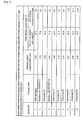
- Fig. 1 is a table showing the relationship of the arithmetic-average surface roughness (Ra) before film formation and the water-droplet contact angle after exposure to 1.0 mW/cm 2 of UV light for 24 hours following film formation and application of engine oil, with respect to retainers.
- Fig. 2 is a table showing the relationship of the arithmetic-average surface roughness (Ra) before film formation and the water-droplet contact angle after exposure to 1.0 mW/cm 2 of UV light for 24 hours following film formation and application of engine oil, with respect to laser radar covers (substrate material: polyimide).
- Fig. 3 is a table showing the relationship of the arithmetic-average surface roughness (Ra) before film formation and the water-droplet contact angle after exposure to 1.0 mW/cm 2 of UV light for 24 hours following film formation and application of engine oil, with respect to substrates of various types.
- Fig. 4 is a plot showing the relationship of the arithmetic-average surface roughness (Ra) before film formation and the water-droplet contact angle after exposure to 1.0 mW/cm 2 of UV light for 24 hours following film formation and application of engine oil, with respect to substrates of various types.
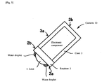
- Fig. 5 is a schematic drawing showing a camera conforming to one embodiment of the present invention.
- the applicant developed a prototype comprising a structure of retention member/photocatalytic film/hydrophilic film, where a photocatalytic film and a hydrophilic film were formed in layers in this order on the surface of the aforementioned retention member using the deposition method, etc.
- the prototype did not provide the expected effect.
- the expected effect could not be achieved simply by forming photocatalytic film/hydrophilic film using the deposition method, sputter method or CVD method on the surface of a commercially available aluminum retainer with black alumite treatment.
- the reason for the failure was considered to be an inappropriate attachment of photocatalytic film/hydrophilic film on the retainer surface.
- black alumite treatment was suspected as a cause of the undesirable result.
- the condition for black alumite treatment was changed in various ways (specifically, by changing the conditions for abrasives such as alumina and ceric oxide or the conditions for buffing or electrolytic polishing, etc.) to produce retainers.
- a retainer with black alumite treatment generates gloss if its arithmetic-average surface roughness (Ra) is 10 ⁇ m or less, in which case the light reflected on the retainer may enter the lens and cause an undesirable effect called halation.
- a retainer with black alumite treatment having an arithmetic-average surface roughness (Ra) of over 10 ⁇ m can be used favorably, because it does not generate gloss and prevents occurrence of halation.
- Ra should be 0.15 ⁇ m or more, or preferably 0.20 ⁇ m or more, in terms of achieving a better balance of desired photocatalytic performance on one hand and the requirements for labor, cost, mass production and quality control on the other.
- the Ra should ideally be 0.65 ⁇ m or less.
- a Ra of 0.30 ⁇ m or less is more preferable.
- Laser radars used for the purpose, among others, of measuring the distance between the subject vehicle and preceding vehicle to control the speed of the subject vehicle accordingly are equipped on certain luxury vehicles to ensure safer vehicle operation. If water droplets or soiling attaches to the cover of a laser radar installed on a vehicle, etc., the laser beam will be scattered and radar sensitivity will drop. In other words, these laser radar devices have a room for further improvement to address the problem of sensitivity drop due to attached water/soiling.
- the inventors of the present invention developed a prototype comprising a structure of cover member/photocatalytic film/hydrophilic film, where a photocatalytic film and a hydrophilic film were formed in layers in this order on the surface of the cover of a laser radar used for the purpose, among others, of measuring the distance between the subject vehicle and preceding vehicle to control the speed of the subject vehicle accordingly.
- the aforementioned photocatalytic film/hydrophilic film was formed on the surface of a laser radar cover made of glass, using the wet method (coating, firing, etc.), deposition method, etc.
- the glass surface was found highly vulnerable to cracking due to contact with small stones, etc., that were kicked into air by the wheels of the preceding vehicle.
- the aforementioned photocatalytic film/hydrophilic film was formed on the surface of a laser radar cover made of common acrylic resin (substrate) using the wet method (coating, firing, etc.). In this case, however, the film did not adhere securely on the acrylic resin surface.
- the aforementioned photocatalytic film/hydrophilic film was formed on the surface of a laser radar cover made of common acrylic resin (substrate) using the deposition method. This time, acrylic resin did not have sufficient heat resistance to withstand the film forming temperature required by the deposition method to produce sufficient photocatalytic property.
- the aforementioned photocatalytic film/hydrophilic film were then formed on a polyimide resin (substrate) surface using the deposition method.
- the level of photocatalytic performance varied significantly depending on the slight difference in the surface roughness of the polyimide resin substrate, as mentioned earlier.
- the same results based on the deposition method were also obtained with the sputter method and CVD method.
- a laser radar cover made of polyimide resin would provide a molded product having a surface roughness corresponding to the surface roughness of its die that has been produced with a finely adjusted surface roughness according to the know-how obtained above.
- use of polyimide resin would allow for mass production at a high yield and in a stable manner of a molded laser radar cover having a Ra of 60 to 100 nm that prominently exhibits photocatalytic property, and polyimide resin material would also provide excellent film adhesion and also ensure enough heat resistance to achieve sufficient photocatalytic performance using the deposition method, sputter method or CVD method.
- covers for laser radars used for the purpose, among others, of measuring the distance between the subject vehicle and preceding vehicle to control the speed of the subject vehicle accordingly should most ideally have prominent hydrophilicity (anti-fogging property) as well as prominent photocatalytic property (anti-soiling property) that ensures that hydrophilicity (anti-fogging property) will be maintained for a long period of time.
- these laser radar covers should preferably have a surface roughness (Ra) of 60 to 100 nm, or more preferably a Ra of 60 to 90 nm.
- the inventors of the present invention also developed a prototype comprising a structure of gear member/photocatalytic film/hydrophilic film, where a photocatalytic film and a hydrophilic film were formed in layers in this order on the surface of a bicycle gear (a gear on which hydrophilic photocatalytic film was formed).
- the aforementioned photocatalytic film/hydrophilic film was formed on the surface of a bicycle gear made of stainless steel (SUS304) using the wet method (coating, firing, etc.). However, the film did not adhere securely on the SUS304 surface.
- the aforementioned photocatalytic film/hydrophilic was formed using the deposition method, sputter method or CVD method on the surface of a bicycle gear made of stainless steel (SUS304), the level of photocatalytic performance varied significantly depending on the slight difference in the surface roughness of the bicycle gear, as mentioned earlier.
- gears and other bicycle parts have complex surface shapes (gear curves, curved surfaces, etc.), and therefore pursuit of uniform surface roughness over the entire surface of a member costs too much and is not practical at the present time.
- producing a gear member whose entire surface is treated to a surface roughness (Ra) of 0.1 ⁇ m or less would require levels of labor, cost, mass production and quality control that are not practical and consequently present significant problems.
- a gear member having a surface roughness (Ra) in a range of 0.65 ⁇ m or less but not below 0.30 ⁇ m over its entire surface-from the viewpoint of labor, cost, mass production and quality control (this way, a gear member having a surface roughness (Ra) in a range of 0.65 ⁇ m or less but not below 0.30 ⁇ m can be mass-produced at a high yield in a stable manner and requiring less quality control).
- the inventors plotted the data obtained by a series of prototypes described above on a single graph. To their surprise, the plot provided a regression expression independent of materials. Further, this regression expression was very reliable and offered extremely high utility in practical applications (refer to Fig. 4 wherein a TiO2 film having a thickness of 200 nm and a SiO2 film having a thickness of 20 nm were formed as the photocatalytic film and the hydrophilic film, and the substrate was heated to temperatures of 300°C or above but not exceeding 450°C).
- surface roughness is generally measured using an interatomic-force microscope in the production of photocatalytic film on exterior automotive mirrors, etc. If the member itself requires a surface roughness of 100 nm or less, or preferably 50 nm or less, in order to satisfy its own characteristic requirement, measuring surface roughness in a small area to the order of nm will make it difficult to achieve the aforementioned regression expression. This conclusion is based on a finding that even when surface roughness was measured by a laser microscope, if the measured area was small, such as 10 ⁇ m x 10 ⁇ m, achieving the above regression expression would become difficult.
- the member does not require a surface roughness of 100 nm or less, or preferably 50 nm or less, in order to satisfy its own characteristic requirement, its arithmetic-average surface roughness (Ra) must be measured in an area of 100 ⁇ m x 100 ⁇ m by a laser microscope in order to achieve the above regression expression.
- the Ra, or arithmetic-average surface roughness, of a 100 ⁇ m x 100 ⁇ m area as measured by a laser microscope had a highly reliable correlation with photocatalytic performance regardless of the material.
- At least one embodiment of the present invention provides a member that accurately exhibits a desired level of photocatalytic performance by way of adjusting the surface roughness of the member to the range specified by the present invention using a method appropriate for the material of the member and in consideration of desired photocatalytic performance, associated cost increase, and so on.
- the present invention includes, but is not limited to, the following embodiments:
- the member being produced in such a way that the surface of the member is adjusted to an arithmetic-average surface roughness (Ra) of 0.78 ⁇ m or less as measured in an area of 100 ⁇ m x 100 ⁇ m by a laser microscope and then photocatalytic film and hydrophilic film are formed in layers in this order on the aforementioned surface using the deposition method, sputter method or CVD method.
- Ra arithmetic-average surface roughness
- This structure allows for production of a member that accurately exhibits a desired level of photocatalytic performance by way of adjusting the surface roughness of the member precisely to the range specified by the present invention using a method appropriate for the material of the member and in consideration of desired photocatalytic performance, associated cost increase, and so on, even when the applicable member is one that does not conventionally guarantee manifestation of actual photocatalytic action and benefits therefrom by simply forming photocatalytic film and hydrophilic film in layers in this order on the surface of the member using the deposition method, sputter method or CVD method.
- the minimum arithmetic-average surface roughness (Ra) as measured in an area of 100 ⁇ m x 100 ⁇ m by a laser microscope is 0.01 ⁇ m, which is the minimum resolution of the laser microscope in the height direction. However, it can be set to 0.09 ⁇ m if higher photocatalytic performance is required, or to 0.08 ⁇ m, 0.07 ⁇ m, 0.06 ⁇ m or 0.05 ⁇ m if higher photocatalytic performance is required together with stability of such performance, or to 0.11 ⁇ m, 0.12 ⁇ m, 0.15 ⁇ m or 0.20 ⁇ m if higher photocatalytic performance is required while any cost increase must be kept to a minimum.
- the material of "a member of the same shape and having the same purpose as the aforementioned member” may be the same as the material of a member that does not conventionally guarantee manifestation of actual photocatalytic action and benefits therefrom by simply forming photocatalytic film and hydrophilic film in layers in this order on the surface of the member using the deposition method-as long as the entire surface of the substrate can be treated to a nearly uniform surface roughness at low cost. If not, however, it is desirable to use a material that allows the entire surface of the substrate to be treated to a nearly uniform surface roughness at low cost.
- a camera having a camera lens or hood glass having a surface exposed to the external environment, and a member for retaining the aforementioned camera lens or hood glass installed on the outer periphery of the aforementioned camera lens or hood glass, characterized in that:
- photocatalytic film and hydrophilic film are formed in layers in this order using the deposition method, sputter method or CVD method on the surface of the camera lens or hood glass having a surface exposed to the external environment;
- the surface of the aforementioned retention member is produced in such a way that the arithmetic-average surface roughness (Ra) of the surface as measured in an area of 100 ⁇ m x 100 ⁇ m by a laser microscope becomes 0.78 ⁇ m or less and that photocatalytic film and hydrophilic film are formed in layers in this order using the deposition method, sputter method or CVD method on at least the surface of the retention member contacting the aforementioned camera lens or hood glass.
- Ra arithmetic-average surface roughness
- This structure allows for production of a retention member for camera lens or hood glass that accurately exhibits a desired level of photocatalytic performance by way of adjusting the surface roughness of the member precisely to the range specified by the present invention using a method appropriate for the material of the member and in consideration of desired photocatalytic performance, associated cost increase, and so on.
- the arithmetic-average surface roughness (Ra) of the camera lens or hood glass as measured in an area of 100 ⁇ m x 100 ⁇ m by a laser microscope was 0.05 ⁇ m or less.
- photocatalytic film and hydrophilic film can be formed in layers in this order also on the entire surface of the part exposed to the external environment, of the surface of the aforementioned retention member for the camera lens or hood glass (for example, the retention surface (2a) and side face (2b) of the retainer (2) for the lens (1) as shown in Fig. 5 ). This prevents the water droplets collecting on the side face (3b) of the retention member from flowing down onto the lens and temporarily reducing the field of view.
- photocatalytic film and hydrophilic film can be formed in layers in this order also on the surface of the camera case member having a surface exposed to the external environment (for example, the side face (3a) and back face (3b) of the case (3) for the camera (10) as shown in Fig. 5 ). This prevents the water droplets collecting on the case member surface from flowing down onto the lens and temporarily reducing the field of view.
- the bicycle part being produced in such a way that the surface of the aforementioned bicycle part is adjusted to an arithmetic-average surface roughness (Ra) of 0.78 ⁇ m or less as measured in an area of 100 ⁇ m x 100 ⁇ m by a laser microscope and then photocatalytic film and hydrophilic film are formed in layers in this order on the aforementioned surface using the deposition method, sputter method or CVD method.
- Ra arithmetic-average surface roughness
- This structure allows for production of a bicycle part that accurately exhibits a desired level of photocatalytic performance by way of adjusting the surface roughness of the bicycle part precisely to the range specified by the present invention using a method appropriate for the material of the bicycle part and in consideration of desired photocatalytic performance, associated cost increase, and so on, even when the applicable bicycle part is one that does not conventionally guarantee manifestation of actual photocatalytic action and benefits therefrom by simply forming photocatalytic film and hydrophilic film in layers in this order on the surface of the part using the deposition method, sputter method or CVD method.
- the present invention according to Structure 3 as explained above can be used favorably on gears, disk brake rotors, hubs, or spokes, nipples and other parts near hubs, i.e., those bicycle parts to which oil attaches easily.
- the present invention according to Structure 3 as explained above can be used favorably on aluminum wheels for automotive tires, etc., that are also subject to attachment of oil, etc.
- a laser radar device having a laser radar unit, and a laser radar cover member having a surface exposed to the external environment, characterized in that:
- the laser radar cover member is a polyimide resin molding
- photocatalytic film and hydrophilic film are formed in layers in this order using the deposition method, sputter method or CVD method on the surface of the aforementioned laser radar cover member that has been produced in such a way that the surface has an arithmetic-average surface roughness (Ra) of 0.78 ⁇ m or less as measured in an area of 100 ⁇ m x 100 ⁇ m by a laser microscope.
- Ra arithmetic-average surface roughness
- This structure allows for production of a laser radar cover member that accurately exhibits a desired level of photocatalytic performance by way of adjusting the surface roughness of the laser radar cover member precisely to the range specified by the present invention using a method appropriate for the material of the member and in consideration of desired photocatalytic performance, associated cost increase, and so on.
- photocatalytic film and hydrophilic film can be formed in layers in this order also on the surface of another member contacting the laser radar cover member or located adjacent to the laser radar cover member. This prevents the water droplets collecting on the surface of any such contacting/adjacent member from flowing down onto the laser radar cover member and temporarily reducing the radar sensitivity.
- Polyimide resin is most desirable as the cover material for laser radars installed on vehicles, etc., for its smoothness and heat resistance, among others.
- Acrylic resin is the second best choice.
- the present invention according to Structure 4 as explained above can also be applied to the cover members for laser radars installed on trains and various other mobile objects.
- the invention according to Structure 5 as explained above allows for production of a member that accurately exhibits a desired level of photocatalytic performance by way of adjusting the surface roughness of the member precisely to the range specified by the present invention using a method appropriate for the material of the member and in consideration of desired photocatalytic performance, associated cost increase, and so on, even when the applicable member is one that does not conventionally guarantee manifestation of actual photocatalytic action and benefits therefrom by simply forming photocatalytic film and hydrophilic film in layers in this order on the surface of the member using the deposition method, sputter method or CVD method.
- achievement of a desired level of photocatalytic performance can be accurately predicted.
- the invention according to Structure 6 as explained above provides a production method for members that accurately exhibit desired photocatalytic performance.
- the invention according to Structure 8 as specified above ensures excellent productivity and high yield in mass production, because a preliminary inspection is conducted on all of the aforementioned members before film formation so that film is formed only on those members whose surface roughness is inside the predetermined range (range specified by the present invention) (by eliminating members whose surface roughness is outside the range specified by the present invention), thereby allowing the total quantity to properly manifest desired photocatalytic performance.
- the measuring method using a laser microscope can inspect members before film formation without damaging or contacting the members. Also, all products on the line can be inspected, or a part of them can be sampled for inspection, using a laser microscope. These features make a laser microscope very useful in the application of the present invention.
- an interatomic-force microscope requires samples to be cut out prior to measurement. These samples are also contacted by the probe, which necessitates a complex measuring procedure. The samples that have been measured are deemed damaged or unduly contacted and therefore cannot be used as products. Of course, 100% inspection is unfeasible using an interatomic-force microscope, so the products on the line cannot be controlled easily using this microscope.
- the arithmetic-average surface roughness (Ra) of the member before film formation as measured in an area of 100 ⁇ m x 100 ⁇ m by a laser microscope, conform to the surface roughness specified above over the entire surface of the aforementioned member or entire surface in the area that requires photocatalytic performance.
- the arithmetic-average surface roughness (Ra) of the member before film formation conform to the surface roughness specified above at a minimum of 3 points, or more preferably at 5 points or 10 points, or most preferably at 20 points, on the entire surface of the aforementioned member. If the surface roughness specified above is satisfied at 10 or more points on the surface of the aforementioned member, it can be expected that desired photocatalytic performance will manifest over the entire surface of the aforementioned member or entire surface in the area that requires photocatalytic performance.
- An embodiment of the present invention is particularly useful on members with a non-flat or curved shape (especially members with a curved shape that makes it difficult to obtain a uniform surface roughness), members with a complex shape, and other members where achievement of a uniform surface roughness is difficult.
- An embodiment of the present invention is particularly useful on members where achievement of a uniform surface roughness is difficult. On these members, pursuit of surface roughness can reduce yield and affect productivity, while such effort may also require complex quality control procedures. On these members, it makes sense to keep their surface roughness at a level near the upper limit cost wise.
- An embodiment of the present invention is particularly useful on members that do not require surface roughness control as their own characteristic requirement and strict control of surface roughness is technically difficult.
- the level of surface roughness that can be pursued is limited by cost, so it makes sense to keep their surface roughness at a level near 0.09 ⁇ m, which is the lower limit cost wise. If the level of surface roughness that can be pursued is limited by cost and keeping to the budgeted cost is particularly important, it makes sense to keep the surface roughness of the member before film formation to a level near the lower limit of 0.10 ⁇ m. It may also make sense to keep the surface roughness to a level near the lower limit of 0.15 ⁇ m, or even near the lower limit of 0.20 ⁇ m.
- the aforementioned hydrophilic film comprises SiO 2 film and the aforementioned photocatalytic film comprises TiO 2 film.
- SiO 2 film is an oxide film and easily generates the OH group, which is a hydrophilic group and contributes to good hydrophilicity.
- the refractive index of SiO 2 film is lower than that of glass plate and close to the refractive indexes of water and air. This keeps refractions on the SiO 2 film surface to a minimum, which in turn prevents generation of double images.
- SiO 2 film causes minimal diffused reflection even when raindrops attach to the surface, thus ensuring good visibility through the surface on which the film is applied.
- SiO 2 film is an inorganic material and thus offers high scratch resistance and heat resistance and provides excellent durability and weather resistance.
- As the hydrophilic film Al 2 O 3 film, TiO 2 film or other oxide films can be used instead of SiO 2 film.
- As the photocatalytic film SrTiO 3 film or KNbO 3 film can be used in stead of TiO 2 film.
- both the photocatalytic film and hydrophilic film may be formed using the same method selected from the deposition method, sputter method and CVD method, or each film may be formed using a different method selected from the same group specified above.
- the thickness of a photocatalytic film such as a TiO 2 film may be about 50 nm to about 400 nm (preferably 100 nm to 300 nm), and the thickness of a hydrophilic film such as a SiO 2 film may be about 1 nm to about 400 nm (preferably 10 nm to 100 nm). Further, in an embodiment, each film can be constituted by multiple layers. Additionally, in an embodiment, the surface on which the photocatalytic film is formed can coated with another layer or a undercoating prior to deposition of the photocatalytic film.
- the surface of the aforementioned hydrophilic film it is desirable that the surface of the aforementioned hydrophilic film have a porous structure. This is because if the hydrophilic film comprising SiO 2 film has a porous surface, wettability will improve due to the capillary effect and this will in turn enhance hydrophilicity and consequently increase the effect of removing water droplets. Furthermore, the pores (gaps) in SiO 2 film will also facilitate the decomposition of soiling and other foreign material in the photocatalytic layer underneath.
- a member that should not generate interference colors to incorporate a material having a refractive index between that of TiO 2 and that of the substrate, such as ITO, SnO 2 , Ta 2 O 5 , ZiO 2 , WO 3 or Al 2 O 3 , between TiO 2 and the substrate and then have SiO 2 on top (in the laminated structure of the substrate/the material with an intermediate refractive index/TiO 2 /SiO 2 ), in order to suppress generation of interference colors of TiO 2 .
- Members that can benefit from this measure include retention members for camera lenses, etc., installed on the outer periphery of the camera lens, etc., (these peripheral members are called "retainer") and cover members for laser radars.
- the applicable member may be made of any of the following materials:
- arithmetic-average surface roughness (Ra) was measured in an area of 100 ⁇ m x 100 ⁇ m by a laser microscope (VK-8510 ultra-depth shape measuring microscope manufactured by Keyence Corporation) on various samples each having a different surface roughness level, and then TiO 2 and SiO 2 were formed on the respective samples by 200 nm and 20 nm, respectively.
- the substrate was heated to temperatures of 300°C or above but not exceeding 450°C.
- UV intensity was measured using a UV intensity meter manufactured by Topcon Corporation, while water-droplet contact angle was measured with the contact-angle measuring system manufactured by Kyowa Interface Science Co., Ltd. FL20S/BL-B manufactured by Matsushita Electric Industrial Co., Ltd. was used as the black light.
- Figs. 3 and 4 show the relationships of the arithmetic-average surface roughness (Ra) of substrate before film formation and the water-droplet contact angle after exposure to 1.0 mW/cm 2 of UV light for 24 hours. A regression line and a regression expression representing these relationships were obtained. The coefficient of determination, R 2 , in this regression expression was 0.9988 (very close to 1.0000), indicating high reliability of the expression.
- Example 1 the same tests were conducted with the sputter method and CVD method (the substrate was heated to temperatures of 300°C or above but not exceeding 450°C in the case of the CVD method, and to temperatures of 150°C or above but not exceeding 450°C in the case of the sputter method), in addition to using the deposition method. Similar results were obtained from the tests using the other two methods.
- photocatalytic film and hydrophilic film were formed in layers in this order, using the deposition method, sputter method or CVD method, on the surfaces of retainers (camera-lens retention members), laser radar cover members made of resin, and bicycle gear members, which were all produced in such a way that the arithmetic-average surface roughness (Ra) as measured in an area of 100 ⁇ m x 100 ⁇ m by a laser microscope became 0.78 ⁇ m or less.
- Ra arithmetic-average surface roughness
- a tape peel test was conducted on the samples produced in Example 1, in order to check the adhesive strength of the samples.
- a piece of Cellotape (trademark) No. 405 manufactured by Nichiban Co., Ltd. was attached on the substrate, after which one end of the tape was held at right angles to the test piece and then pulled up in order to determine whether or not the film would peel off, as a measure of the film's adhesive strength.
- each of these samples with an anti-fogging film exhibited an excellent anti-defogging effect sufficient in practical applications-a level higher than what was measured on members having an arithmetic-average surface roughness (Ra) of over 0.78 ⁇ m on their substrate.
- the present invention can be suitably used in various applications-particularly on retention members for camera lenses and hood glasses that are used in cameras installed in high places as surveillance cameras or in other outdoor locations where maintenance is difficult.
- the present invention is particularly suited on bicycle gears and disc brake rotors to which oil attaches easily.
- the present invention is particularly suited on cover materials for laser radars used for the purpose, among others, of measuring the distance between the subject vehicle and preceding vehicle to control the speed of the subject vehicle accordingly.
Landscapes
- Chemical & Material Sciences (AREA)
- Organic Chemistry (AREA)
- Engineering & Computer Science (AREA)
- Chemical Kinetics & Catalysis (AREA)
- Materials Engineering (AREA)
- Metallurgy (AREA)
- Mechanical Engineering (AREA)
- General Chemical & Material Sciences (AREA)
- Inorganic Chemistry (AREA)
- Geochemistry & Mineralogy (AREA)
- Life Sciences & Earth Sciences (AREA)
- Catalysts (AREA)
- Chemical Vapour Deposition (AREA)
- Laminated Bodies (AREA)
- Surface Treatment Of Glass (AREA)
- Physical Vapour Deposition (AREA)
Claims (18)
- Artikel, umfassend:a) eine Oberfläche,
wobei das Material der Oberfläche ausgewählt ist aus der Gruppe aus Edelstahl, kalt gewalztem Stahlblatt, Aluminium, Aluminiumoxid (alumite), Eisen, Nickel, Titan, Messing; Polyimid, ABS (Polyacrylnitril-Butadien-Styrol-Harz), PP (Polypropylen), PE (Polyethylen), PS (Polysterol), PMMA (Acryl), PET (Polyethylenterephthalat), PPE (Polyphenylenether), PA (Nylon/Polyamid), PC (Polycarbonat), POM (Polyacetal), PBT (Polybutylenterephthalat), PPS (Polyphenylensulfid), PEEK (Polyetheretherketon), LCP (Flüssigkristall-Polymer), Fluorharz, Urethan-Harz, Elastomer; Glas und Keramik,
wobei die Oberfläche eine arithmetische Durchschnitts-Oberfächenrauheit (Ra) von 0,78 µm oder weniger aufweist, wie auf einer Fläche von 100 µm x 100 µm mittels eines Lasermikroskops gemessen;b) einen fotokatalytischen Film, der auf der Oberfläche abgelagert wurde,
wobei der fotokatalytische Film aus TiO2 gebildet wird;
wobei der fotokatalytische Film aus TiO2 eine Dicke von 50 bis 400 nm aufweist; undc) einen hydrophilen Film, der auf dem fotokatalytischen Film abgelagert wurde und der äußeren Umgebung ausgesetzt wurde,wobei der hydrophile Film aus SiO2 gebildet,
wobei der hydrophile Film aus SiO2 eine Dicke von 1 bis 400 nm aufweist und eine poröse Struktur hat. - Artikel gemäß Anspruch 1, wobei der fotokatalytische Film und der hydrophile Film Filme sind, die mittels physikalischer und chemischer Gasphasenabscheidung abgelagert wurden.
- Artikel gemäß Anspruch 1 oder 2, wobei eine Oberfläche des hydrophilen Filmes einen Wassertröpfchen-Kontaktwinkel von ungefähr 20° oder weniger aufweist, wie nach Bestrahlung für 24 Stunden mit einem Schwarzlicht, das eine Intensität von 1,0 mW/cm2 aufweist, gemessen.
- Artikel gemäß einem der Ansprüche 1 bis 3, welcher eine Kamera ist, umfassend eine Kameralinse oder Abdeckhaubenglas und eine Aufnahme, die die Kameralinse oder Abdeckhaubenglas an ihrer äußeren Peripherie aufnimmt, wobei die Oberfläche eine Oberfläche der Aufnahme umfasst.
- Artikel gemäß Anspruch 4, wobei die Oberfläche der Aufnahme eine Ra von 0,60-0,78 µm aufweist und eine Oberfläche des hydrophilen Filmes einen Wassertröpfchen-Kontaktwinkel von ungefähr 15° bis ungefähr 20° aufweist, wie nach Bestrahlung für 24 Stunden mit einem Schwarzlicht, das eine Intensität von 1,0 mW/cm2 aufweist, gemessen.
- Artikel gemäß einem der Ansprüche 1 bis 3, welcher ein Fahrradteil ist, wobei die Oberfläche eine Oberfläche des Fahrradteiles umfasst.
- Artikel nach einem der Ansprüche 1 bis 3, welcher eine Laser-Radar-Vorrichtung ist, umfassend eine Laser-Radar-Einheit und ein Laser-Radar-Abdeckungsteil, wobei das Laser-Radar-Abdeckungsteil ein Polyimid-Harz-Formteil ist, und die Oberfläche eine Oberfläche des Laser-Radar-Abdeckungsteils umfasst.
- Artikel gemäß Anspruch 7, wobei die Oberfläche des Laser-Radar-Abdeckungsteils eine Ra von 0,2 µm oder weniger aufweist und eine Oberfläche des hydrophilen Films einen Wassertröpfchen-Kontaktwinkel von ungefähr 4° oder weniger aufweist, wie nach Bestrahlung für 24 Stunden mit einem Schwarzlicht, das eine Intensität von 1,0 mW/cm2 aufweist, gemessen.
- Verfahren zur Produktion eines Artikels, der fotokatalytische Aktion manifestiert, umfassend:i) Bestimmen eines Gebietes auf einem Artikel, welcher fotokatalytische Aktion manifestieren soll, wobei das Material des Gebietes eines Artikels ausgewählt ist aus der Gruppe bestehend aus Edelstahl, kalt gewalztem Stahlblatt, Aluminium, Aluminiumoxid (alumite), Eisen, Nickel, Titan, Messing; Polyimid, ABS (Polyacrylnitril-Butadien-Styrol-Harz), PP (Polypropylen), PE (Polyethylen), PS (Polysterol), PMMA (Acryl), PET (Polyethylenterephthalat), PPE (Polyphenylenether), PA (Nylon/Polyamid), PC (Polycarbonat), POM (Polyacetal), PBT (Polybutylenterephthalat), PPS (Polyphenylensulfid), PEEK (Polyetheretherketon), LCP (Flüssigkristall-Polymer), Fluorharz, Urethan-Harz, Elastomer; Glas und Keramik;ii) Bestimmen, ob das Gebiet eine arithmetische Durchschnitts-Oberflächenrauheit (Ra) von 0,78 µm oder weniger aufweist, wie in einem Gebiet von 100 µm x 100 µm mittels eines Lasermikroskops gemessen;iii) Wenn Ra mehr als 0,78 µm ist, Einstellen der Ra auf 0,78 µm oder weniger;iv) Formen eines fotokatalytischen Films auf dem Gebiet mittels physikalischer oder chemischer Gasphasenabscheidung,
wobei der fotokatalytische Film aus TiO2 gebildet wird;
wobei der fotokatalytische Film aus TiO2 eine Dicke von 50 bis 400 nm aufweist, undv) Bilden eines hydrophilen Films auf dem photokatalytischen Film mittels physikalischer oder chemischer Gasphasenabscheidung,
wobei der hydrophile Film aus SiO2 gebildet wird,
wobei der hydrophile Film aus SiO2 eine Dicke von 1 bis 400 nm aufweist und eine poröse Struktur hat. - Verfahren gemäß Anspruch 9, wobei eine Oberfläche des hydrophilen Filmes einen Wassertröpfchen-Kontaktwinkel von ungefähr 20° oder weniger aufweist, wie nach Bestrahlung für 24 Stunden mit einem Schwarzlicht, das eine Intensität von 1,0 mW/cm2 aufweist, gemessen.
- Verfahren gemäß Anspruch 9 oder 10, wobei der Artikel eine Kamera ist, umfassend eine Kameralinse oder Abdeckhaubenglas und eine Aufnahme, die die Kameralinse oder Abdeckhaubenglas an ihrer äußeren Peripherie aufnimmt, wobei die Oberfläche eine Oberfläche der Aufnahme umfasst.
- Verfahren gemäß Anspruch 11, wobei der Schritt des Einstellens der Ra umfasst: Einstellen der Ra auf 0,60-0,78 µm, wobei eine Oberfläche des hydrophilen Films einen Wassertröpfchen-Kontaktwinkel von ungefähr 15° bis ungefähr 20° aufweist, wie nach Bestrahlung für 24 Stunden mit einem Schwarzlicht, das eine Intensität von 1,0 mw/cm2 aufweist, gemessen.
- Verfahren gemäß Anspruch 9 oder 10, wobei der Artikel ein Fahrradteil ist, wobei die Oberfläche eine Oberfläche des Fahrradteiles umfasst.
- Verfahren gemäß Anspruch 9 oder 10, wobei der Artikel eine Laser-Radar-Vorrichtung ist, umfassend eine Laser-Radar-Einheit und ein Laser-Radar-Abdeckungsteil, wobei das Laser-Radar-Abdeckungsteil ein Polyimid-Harz-Formteil ist, und die Oberfläche eine Oberfläche des Laser-Radar-Abdeckungsteils umfasst.
- Verfahren gemäß Anspruch 14, wobei der Schritt des Einstellens der Ra umfasst: Einstellen der Ra auf 0,2 µm oder weniger, wobei eine Oberfläche des hydrophilen Films einen Wassertröpfchen-Kontaktwinkel von ungefähr 4° oder weniger aufweist, wie nach Bestrahlung für 24 Stunden mit einem Schwarzlicht, das eine Intensität von 1,0 mW/cm2 aufweist, gemessen.
- Verfahren für die Produktion eines Artikels, der fotokatalytische Aktion manifestiert, umfassend:i) Erhalten einer Regressionslinie oder eines Regressionsausdrucks oder beides für eine Beziehung zwischen der arithmetischen Durchschnitts-Oberflächenrauheit (Ra) einer Oberfläche eines Artikels, wie in einem Gebiet von 100 µm x 100 µm mittels eines Lasermikroskops gemessen, und eines Wassertröpfchen-Kontaktwinkels (Ca) einer oberen Oberfläche des Artikels, wie nach Bestrahlung für 24 Stunden mit einem Schwarzlicht, das eine Intensität von 1,0 mW/cm2 aufweist, gemessen, wobei eine fotokatalytischer Film und ein hydrophiler Film in Reihenfolge auf der Oberfläche mittels physikalischer oder chemischer Gasphasenabscheidung unter einer gegebenen Bedingung gebildet werden;ii) Auswählen eines Artikels, der behandelt werden soll;iii) Bestimmen eines gewünschten Ca auf einem Gebiet des Artikels;iv) Bestimmen einer gewünschten Ra auf dem Gebiet, welche 0,78 µm oder weniger ist, für den gewünschten Ca basierend auf der Regressionslinie oder des Regressionsausdrucks oder beiden;v) Bearbeiten des Gebietes, um seine Ra auf die gewünschte Ra einzustellen,vi) Bilden eines fotokatalytischen Films und eines hydrophilen Films in Reihenfolge auf dem Gebiet mittels physikalischer oder chemischer Gasphasenabscheidung unter der gegebenen Bedingung;wobei das Material der Oberfläche auf einem Artikel ausgewählt ist aus der Gruppe aus
Edelstahl, kalt gewalztem Stahlblatt, Aluminium, Aluminiumoxid (alumite), Eisen, Nickel, Titan, Messing; Polyimid, ABS (Polyacrylnitril-Butadien-Styrol-Harz), PP (Polypropylen), PE (Polyethylen), PS (Polysterol), PMMA (Acryl), PET (Polyethylenterephthalat), PPE (Polyphenylenether), PA (Nylon/Polyamid), PC (Polycarbonat), POM (Polyacetal), PBT (Polybutylenterephthalat), PPS (Polyphenylensulfid), PEEK (Polyetheretherketon), LCP (Flüssigkristall-Polymer), Fluorharz, Urethan-Harz, Elastomer; Glas und Keramik;
wobei der fotokatalytische Film aus TiO2 gebildet wird;
wobei der fotokatalytische Film aus TiO2 eine Dicke von 50 bis 400 nm aufweist, und
wobei der hydrophile Film eine poröse Struktur aufweist und aus SiO2 gebildet wird,
wobei der hydrophile Film aus SiO2 eine Dicke von 1 bis 400 nm aufweist und eine poröse Struktur hat. - Verfahren gemäß Anspruch 16, wobei der Schritt des Erhaltens der Regressionslinie oder des Regressionsausdrucks oder beider verschiedene Artikel verwendet, die aus verschiedenen Materialien hergestellt sind.
- Verfahren gemäß Anspruch 16, wobei eine Oberfläche des hydrophilen Films einen Ca von ungefähr 20° oder weniger aufweist.
Applications Claiming Priority (1)
| Application Number | Priority Date | Filing Date | Title |
|---|---|---|---|
| JP2004335697A JP2006142206A (ja) | 2004-11-19 | 2004-11-19 | 光触媒膜坦持部材 |
Publications (2)
| Publication Number | Publication Date |
|---|---|
| EP1661867A1 EP1661867A1 (de) | 2006-05-31 |
| EP1661867B1 true EP1661867B1 (de) | 2009-05-13 |
Family
ID=35614674
Family Applications (1)
| Application Number | Title | Priority Date | Filing Date |
|---|---|---|---|
| EP05019047A Ceased EP1661867B1 (de) | 2004-11-19 | 2005-09-01 | Artikel mit photokatalytische Beschichtung |
Country Status (5)
| Country | Link |
|---|---|
| US (1) | US20060110578A1 (de) |
| EP (1) | EP1661867B1 (de) |
| JP (1) | JP2006142206A (de) |
| CN (1) | CN1776016A (de) |
| DE (1) | DE602005014435D1 (de) |
Families Citing this family (4)
| Publication number | Priority date | Publication date | Assignee | Title |
|---|---|---|---|---|
| DE102010046991B4 (de) * | 2010-09-30 | 2016-12-29 | Schott Ag | Hitzeschutzverglasung, deren Verwendung und Verfahren zu deren Herstellung |
| MY154239A (en) * | 2012-07-27 | 2015-05-29 | Nissan Motor | Vehicle-mounted camera device |
| US10039442B2 (en) | 2014-02-07 | 2018-08-07 | Sur-Seal Corporation | Anti-fog film for an endoscope |
| US10317578B2 (en) * | 2014-07-01 | 2019-06-11 | Honeywell International Inc. | Self-cleaning smudge-resistant structure and related fabrication methods |
Family Cites Families (20)
| Publication number | Priority date | Publication date | Assignee | Title |
|---|---|---|---|---|
| JPH09192498A (ja) * | 1996-01-24 | 1997-07-29 | Toray Ind Inc | 薄膜状光触媒体およびその製造方法 |
| JP2901550B2 (ja) * | 1996-07-26 | 1999-06-07 | 株式会社村上開明堂 | 防曇素子 |
| JP3700358B2 (ja) * | 1996-12-18 | 2005-09-28 | 日本板硝子株式会社 | 防曇防汚ガラス物品 |
| JP3250607B2 (ja) * | 1997-04-08 | 2002-01-28 | 東陶機器株式会社 | 光触媒性親水性被膜の形成方法ならびに光触媒性親水性被膜形成用基材洗浄剤および光触媒性親水性被膜形成材料 |
| EP1376228B1 (de) * | 1997-08-08 | 2010-10-13 | Dai Nippon Printing Co., Ltd. | Verfahren zur Herstellung einer Linse |
| JPH1171686A (ja) * | 1997-08-29 | 1999-03-16 | Nisshin Steel Co Ltd | 耐雨筋汚れ付着性に優れたほうろう被覆ステンレス鋼板及びその製造方法 |
| JPH11179213A (ja) * | 1997-12-22 | 1999-07-06 | Mitsubishi Paper Mills Ltd | 環境浄化素材およびそれを用いた環境浄化材料 |
| JP2000279905A (ja) * | 1998-02-06 | 2000-10-10 | Toto Ltd | 複合材の清浄化方法及びセルフクリーニング性複合材機構 |
| JP2000135755A (ja) * | 1998-07-17 | 2000-05-16 | Toto Ltd | 親水性複合材 |
| JP2000053449A (ja) * | 1998-08-06 | 2000-02-22 | Murakami Corp | 防曇鏡およびその製造方法 |
| JP2001040245A (ja) * | 1999-07-30 | 2001-02-13 | Toto Ltd | 光触媒性親水性塗料組成物及び光触媒性親水性塗膜 |
| JP2002239396A (ja) * | 2001-02-16 | 2002-08-27 | Hitachi Maxell Ltd | 光触媒担持構造体及びその製造方法 |
| JP2002370026A (ja) * | 2001-06-14 | 2002-12-24 | Sumitomo Chem Co Ltd | 光触媒体およびそれを用いる光触媒機能製品 |
| JP2003221672A (ja) * | 2002-01-29 | 2003-08-08 | Dainippon Printing Co Ltd | 酸化チタン薄膜とその製造方法及び酸化チタン薄膜の積層体 |
| JP3896453B2 (ja) * | 2002-03-18 | 2007-03-22 | 独立行政法人産業技術総合研究所 | 光触媒機能と低放射率特性を併せ持つガラス基材及びその製造方法 |
| TWI276613B (en) * | 2002-04-05 | 2007-03-21 | Murakami Corp | Composite material |
| JP4118086B2 (ja) | 2002-05-31 | 2008-07-16 | トヨタ自動車株式会社 | 親水性を有する防曇防汚性薄膜の製造方法 |
| GB2398705B (en) | 2003-02-21 | 2005-08-10 | Toshiba Res Europ Ltd | Automatic wireless connection selection |
| JP2004335697A (ja) | 2003-05-07 | 2004-11-25 | Sumitomo Electric Ind Ltd | 接合型電界効果トランジスタ、その製造方法および半導体装置 |
| US7148313B2 (en) * | 2004-03-26 | 2006-12-12 | Teijin Chemicals, Ltd. | Polycarbonate resin composition and molded articles thereof |
-
2004
- 2004-11-19 JP JP2004335697A patent/JP2006142206A/ja active Pending
-
2005
- 2005-08-01 US US11/194,363 patent/US20060110578A1/en not_active Abandoned
- 2005-08-05 CN CN200510089183.XA patent/CN1776016A/zh active Pending
- 2005-09-01 EP EP05019047A patent/EP1661867B1/de not_active Ceased
- 2005-09-01 DE DE602005014435T patent/DE602005014435D1/de not_active Expired - Lifetime
Also Published As
| Publication number | Publication date |
|---|---|
| DE602005014435D1 (de) | 2009-06-25 |
| JP2006142206A (ja) | 2006-06-08 |
| EP1661867A1 (de) | 2006-05-31 |
| US20060110578A1 (en) | 2006-05-25 |
| CN1776016A (zh) | 2006-05-24 |
Similar Documents
| Publication | Publication Date | Title |
|---|---|---|
| EP2423713B1 (de) | Optisches Element, Verfahren zu dessen Herstellung und optisches System | |
| US20130202866A1 (en) | Mechanically stable nanoparticle thin film coatings and methods of producing the same | |
| Schulz et al. | Vacuum coating of plastic optics | |
| US20090068425A1 (en) | Decorated resin molded article and method for producing the same | |
| KR20120083436A (ko) | 감소된 마찰 특성을 갖는 장치 | |
| KR20010032164A (ko) | 저항성 표면을 갖는 반사기 | |
| JP2011116182A (ja) | 自動車用樹脂ガラス及びその製造方法 | |
| EP1661867A1 (de) | Artikel mit photokatalytische Beschichtung | |
| JP2000053449A (ja) | 防曇鏡およびその製造方法 | |
| JP2015040945A (ja) | 車載カメラ用レンズユニット | |
| JP2015066849A (ja) | 防汚体及びその製造方法 | |
| US6645608B2 (en) | Reflection reducing coating | |
| EP1255129A2 (de) | Verfahren zum Herstellen eines optischen Bauteils mit einer wasserabstossenden Dünnschicht | |
| JPH0798401A (ja) | 反射防止膜及び反射防止部材 | |
| JP2000028811A (ja) | 再帰反射性を有する反射体及びその製造方法 | |
| JP2001183506A (ja) | 光学素子及び表示装置 | |
| US20130170059A1 (en) | Mirror with optional permanent protective film, and/or methods of making the same | |
| CN115732920A (zh) | 装饰性pvd涂覆物品和天线罩及其制造方法 | |
| CN110383112A (zh) | 透镜和透镜的制造方法 | |
| JP2004126532A (ja) | 光学部材 | |
| JP2024153699A (ja) | 光学部材及びレンズユニット | |
| JP2000237678A (ja) | 親水性被膜形成方法及び親水性被膜 | |
| JP7499568B2 (ja) | レンズユニット、光学ユニットおよびレンズに親水膜を形成する方法 | |
| JP2005199572A (ja) | 汚染防止型反射防止膜及び表示装置 | |
| Phillips et al. | Progress toward high-performance astronomical coatings |
Legal Events
| Date | Code | Title | Description |
|---|---|---|---|
| PUAI | Public reference made under article 153(3) epc to a published international application that has entered the european phase |
Free format text: ORIGINAL CODE: 0009012 |
|
| AK | Designated contracting states |
Kind code of ref document: A1 Designated state(s): AT BE BG CH CY CZ DE DK EE ES FI FR GB GR HU IE IS IT LI LT LU LV MC NL PL PT RO SE SI SK TR |
|
| AX | Request for extension of the european patent |
Extension state: AL BA HR MK YU |
|
| 17P | Request for examination filed |
Effective date: 20060614 |
|
| 17Q | First examination report despatched |
Effective date: 20060717 |
|
| AKX | Designation fees paid |
Designated state(s): DE GB |
|
| GRAP | Despatch of communication of intention to grant a patent |
Free format text: ORIGINAL CODE: EPIDOSNIGR1 |
|
| GRAS | Grant fee paid |
Free format text: ORIGINAL CODE: EPIDOSNIGR3 |
|
| GRAA | (expected) grant |
Free format text: ORIGINAL CODE: 0009210 |
|
| AK | Designated contracting states |
Kind code of ref document: B1 Designated state(s): DE GB |
|
| REG | Reference to a national code |
Ref country code: GB Ref legal event code: FG4D |
|
| REF | Corresponds to: |
Ref document number: 602005014435 Country of ref document: DE Date of ref document: 20090625 Kind code of ref document: P |
|
| PLBE | No opposition filed within time limit |
Free format text: ORIGINAL CODE: 0009261 |
|
| STAA | Information on the status of an ep patent application or granted ep patent |
Free format text: STATUS: NO OPPOSITION FILED WITHIN TIME LIMIT |
|
| 26N | No opposition filed |
Effective date: 20100216 |
|
| GBPC | Gb: european patent ceased through non-payment of renewal fee |
Effective date: 20090901 |
|
| PG25 | Lapsed in a contracting state [announced via postgrant information from national office to epo] |
Ref country code: GB Free format text: LAPSE BECAUSE OF NON-PAYMENT OF DUE FEES Effective date: 20090901 |
|
| PGFP | Annual fee paid to national office [announced via postgrant information from national office to epo] |
Ref country code: DE Payment date: 20140827 Year of fee payment: 10 |
|
| REG | Reference to a national code |
Ref country code: DE Ref legal event code: R119 Ref document number: 602005014435 Country of ref document: DE |
|
| PG25 | Lapsed in a contracting state [announced via postgrant information from national office to epo] |
Ref country code: DE Free format text: LAPSE BECAUSE OF NON-PAYMENT OF DUE FEES Effective date: 20160401 |