EP1661669A2 - Gerät zur Erzeugung eines Bearbeitungsprogrammes - Google Patents
Gerät zur Erzeugung eines Bearbeitungsprogrammes Download PDFInfo
- Publication number
- EP1661669A2 EP1661669A2 EP05016424A EP05016424A EP1661669A2 EP 1661669 A2 EP1661669 A2 EP 1661669A2 EP 05016424 A EP05016424 A EP 05016424A EP 05016424 A EP05016424 A EP 05016424A EP 1661669 A2 EP1661669 A2 EP 1661669A2
- Authority
- EP
- European Patent Office
- Prior art keywords
- work
- processing program
- processing
- posture
- robot
- Prior art date
- Legal status (The legal status is an assumption and is not a legal conclusion. Google has not performed a legal analysis and makes no representation as to the accuracy of the status listed.)
- Withdrawn
Links
- 238000012545 processing Methods 0.000 claims abstract description 171
- 230000000007 visual effect Effects 0.000 claims abstract description 22
- 238000000034 method Methods 0.000 claims description 37
- 230000005856 abnormality Effects 0.000 claims description 20
- 238000004891 communication Methods 0.000 abstract description 6
- 230000036544 posture Effects 0.000 abstract 2
- 238000010586 diagram Methods 0.000 description 18
- 238000012937 correction Methods 0.000 description 8
- 238000011960 computer-aided design Methods 0.000 description 6
- 230000002093 peripheral effect Effects 0.000 description 5
- 238000004088 simulation Methods 0.000 description 5
- 238000007796 conventional method Methods 0.000 description 2
- 238000003384 imaging method Methods 0.000 description 2
- 230000002452 interceptive effect Effects 0.000 description 2
- 238000007792 addition Methods 0.000 description 1
- 238000003466 welding Methods 0.000 description 1
Images


Classifications
-
- B—PERFORMING OPERATIONS; TRANSPORTING
- B25—HAND TOOLS; PORTABLE POWER-DRIVEN TOOLS; MANIPULATORS
- B25J—MANIPULATORS; CHAMBERS PROVIDED WITH MANIPULATION DEVICES
- B25J9/00—Programme-controlled manipulators
- B25J9/16—Programme controls
- B25J9/1656—Programme controls characterised by programming, planning systems for manipulators
- B25J9/1664—Programme controls characterised by programming, planning systems for manipulators characterised by motion, path, trajectory planning
- B25J9/1666—Avoiding collision or forbidden zones
-
- B—PERFORMING OPERATIONS; TRANSPORTING
- B25—HAND TOOLS; PORTABLE POWER-DRIVEN TOOLS; MANIPULATORS
- B25J—MANIPULATORS; CHAMBERS PROVIDED WITH MANIPULATION DEVICES
- B25J9/00—Programme-controlled manipulators
- B25J9/16—Programme controls
- B25J9/1656—Programme controls characterised by programming, planning systems for manipulators
- B25J9/1671—Programme controls characterised by programming, planning systems for manipulators characterised by simulation, either to verify existing program or to create and verify new program, CAD/CAM oriented, graphic oriented programming systems
Definitions
- the present invention relates to a processing program generating device that generates a processing program, with an offline programming device using a work to be processed and a robot model, corrects the processing program, and generates a final processing program to be used by a robot to execute the processing.
- an offline programming device is employed to generate a processing program using a shape model of the work and a robot model.
- a visual sensor or the like is used to acquire images of the position and the posture of the work, thereby obtaining a positional deviation and a posture deviation of the work based on the obtained images.
- a processing program generated by the offline programming device is corrected by using these deviations, thereby generating an actual processing program for the processing.
- the visual sensor detects a position and a posture of the work. Deviations between the position and the posture of the work prepared by the processing program and the detected position and the detected posture of the work are corrected so as to generate an actual processing program.
- a stroke limit i.e., a movable range
- a stroke limit i.e., a movable range
- a processing program generating device that generates a processing program for processing a work with a robot
- the processing program generating device including: a display means for displaying a shape model of the work on a display screen; a means for assigning both or one of vertexes and an edge line of the shape model of the work displayed on the screen; a means for assigning a posture of a processing tool; a means for generating a route based on both or one of the vertexes and the edge line that are assigned, and generating a provisional processing program so that the processing tool becomes in the assigned posture of the processing tool in the route; a visual sensor that acquires an image of an area of the work processed by the processing tool, and detects a position and a posture of the work; and a means for correcting the generated provisional processing program based on the position and the posture of the work detected by the visual sensor, thereby generating an actual processing program to be used to process the actual work.
- a processing program generating device that generates a processing program for processing a work with a robot
- the processing program generating device including: a display means for displaying a shape model of the work on a display screen; a means for assigning a surface of the work to be processed on the displayed screen, and inputting a processing start point, a processing direction, a pitch amount, and a pitch direction; a means for setting a posture of a processing tool; a means for generating a route which moves on the assigned surface from the processing start point while shifting the route in an input processing direction by the pitch amount, and generating a provisional processing program so that the processing tool becomes in the posture of the processing tool set in each route; a visual sensor that acquires an image of an area of the work processed by the processing tool, and detects a position and a posture of the work; and a means for correcting the generated provisional processing program based on the position and the posture of the work detected by the visual sensor, thereby generating
- the processing program generating device wherein the means for generating the provisional processing program sets the assigned vertexes as teaching points, sets points at both ends of the assigned edge line as teaching points, sets a straight line route between the teaching point of the assigned vertexes and the other teaching point, sets an edge line route between the assigned teaching points at both ends of the edge line, thereby sequentially obtaining a continuous route in the assigned order of the vertexes and the edge line, and generates the provisional processing program for the generated route so that the processing tool becomes in the assigned posture of the processing tool.
- the processing program generating device according to any one of the first to the third aspects, wherein the means for generating the actual processing program to be used to process the actual work corrects coordinate positions and the posture of the teaching points prepared by the generated provisional processing program, or the points of origin and the posture in a coordinate system that defines the teaching points prepared by the provisional processing program, thereby generating the actual processing program to be used to process the actual work.
- the processing program generating device according to any one of the first to the fourth aspects, wherein the visual sensor includes a camera, and the camera is fitted to a robot that has the processing tool.
- the processing program generating device according to any one of the first to the fifth aspects, wherein the processing tool is fitted to plural robots, and each robot processes one work.
- the processing program generating device according to any one of the first to the sixth aspects, the processing program generating device further including: a means for simulating the operation of the generated actual processing program to be used to process the actual work, and checking whether the processing can be carried out normally in all the routes; and a means for generating an alarm when an abnormality is detected.
- the processing program generating device further including: a means for simulating the operation of the generated actual processing program to be used to process the actual work, and checking whether the work is within a permissible moving range of each axis of the robot in all the routes; and a means for moving the work to a processable position when it is detected that the work exceeds the permissible moving range.
- the processing program generating device further including: a first robot that has the processing tool and processes the work; and a second robot that holds the work, wherein the second robot constitutes the means for moving the work to the processable position.
- the processing program generating device wherein the work is mounted on a movable carriage, and the carriage constitutes the means for moving the work to the processable position.
- the processing program generating device further including: a means for simulating the operation of the generated actual processing program to be used to process the actual work, and checking the occurrence of interference between the robot and other objects in all the routes; and a means for correcting the position and the posture at the teaching points prepared by the processing program to a position and a posture of avoiding interference when the interference is detected.
- a provisional processing program is generated by assigning vertexes and an edge line of a work shape, based on work shape data and the like that is generated by a computer-aided design system (CAD).
- CAD computer-aided design system
- a provisional processing program for processing a surface is generated by setting the surface, a processing direction, a processing pitch and a pitch direction. Therefore, in the present invention, the provisional processing program can be generated easily. Further, because the actual processing program is generated from the provisional processing program based on the position and the posture of the actual work that are imaged by the visual sensor, the processing program can be generated easily.
- both or one of the position and the posture of the work can be corrected so that the work can be processed within a stroke limit of each axis of the robot, without using special tools. Further, it is possible to prevent the robot from interfering with other objects.
- Fig. 1 is a schematic diagram of a processing program generating device (i.e., a program generating and processing system) according to a first embodiment of the present invention.
- a processing program generating device i.e., a program generating and processing system
- two robots 2 and 3 remove flashes from a work 6 that is mounted on a carriage 7.
- the two robots 2 and 3, two visual sensors 4 and 5, and a personal computer (PC) 1 as an offline programming device are connected to each other in a local area network (LAN) using a communication line 10.
- Robot control units 2a and 3a of the robots 2 and 3 respectively are connected to the communication line 10, and control robot mechanism parts 2b and 3b respectively.
- Processing tools 8 and 9, and cameras 4b and 5b of the visual sensors 4 and 5, consisting of cameras and image processing units respectively, are fitted to the front ends of the arms of the robot mechanism parts 2b and 3b respectively, thereby making it possible to acquire images of the processing areas of the work 6.
- Image processing units 4a and 5a are connected to the cameras 4b and 5b respectively.
- the image processing units 4a and 5a are connected to the communication line 10.
- the work 6 to be processed by the processing tools 8 and 9 is mounted on the carriage 7.
- a CAD system is connected to the communication line.
- the CAD system generates work shape model data, shape model data of each robot, and model data of a peripheral unit. These model data are stored in the offline programming device 1.
- the offline programming device 1 may generate the work shape model data, the shape model data of each robot, and the model data of the peripheral unit. These model data may be also stored in the offline programming device 1 via a recording medium.
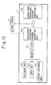
- Fig. 10 is a block diagram of the processing program generating device according to the present invention.
- the offline programming device 1 includes a display unit 104, an assigning unit 101, and a provisional processing program generating unit 105.
- the assigning unit 101 assigns vertexes, an edge line, and a surface of an image of the work to be processed on the shape of the image of a work shape model displayed on the display unit 104.
- the provisional processing program generating unit 105 generates a provisional processing program based on this assignment.
- the offline programming device 1 further includes an actual work processing program generating unit 106 that makes the cameras 4b and 5b of the visual sensors 4 and 5 acquire images of the actual work 6, detects a position and a posture of the work, obtains a deviation between a position and a posture of the work shape model prepared by the offline programming device 1 and the detected position and the detected posture of the work, corrects the provisional processing program using the deviation amount as a correction amount, and generates an actual processing program. This is described in detail later.
- Fig. 2 is a schematic diagram of a processing program generating device and a processing system according to a second embodiment of the present invention.
- elements that are identical with those of the device according to the first embodiment shown in Fig. 1 are designated by some reference numerals.
- the processing tool 8 is fitted to the one robot 2 and the other robot 3 holds the work 6 with a hand 11, so as to process the work 6.
- the personal computer (PC) 1 as the offline programming device, the robot control units 2a and 3a of the robots 2 and 3 respectively, and the image processing unit 4a of the visual sensor 4 are connected to the communication line 10.
- the processing tool 8 and the camera 4b of the visual sensor 4 are fitted to the front end of the arm of the robot mechanism part 2b of the robot 2.
- the hand 11 is fitted to the front end of the arm of the robot mechanism part 3b of the robot 3 so that the hand 11 holds the work 6.
- a processing program is generated in a similar manner to that of the first embodiment, except for the following. While the carriage 7 moves the work 6 in the first embodiment, the robot 3 moves the work 6 in the second embodiment.
- the robot 3 moves the work 6 to enable the robot 2 to process the work 6.
- the carriage 7 moves the work 6 in this case.
- the assigning unit 101 of the offline programming device 1 assigns vertexes, an edge line, and a surface of a shape model of the work in the order of the processing.
- the offline programming device 1 generates a provisional processing program based on this assignment.
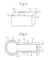
- Fig. 3 is an explanatory diagram of a method of generating a provisional processing program by assigning vertexes.
- a CAD device generates work shape model data
- the offline programming device 1 generates work shape model data.
- a work shape image 6' is drawn on the display screen of the display unit 104 of the offline programming device 1, using coordinate values of the work shape model data.
- the assigning unit 101 that is, a pointing device such as a mouse, is used to assign vertexes of the work shape image 6' following the processing procedure.
- the vertexes as teaching points are connected by straight lines in the assigning order, thereby forming a processing route.
- the vertexes are assigned in the order of P1, P2, P3, P4, and P1 as the teaching points, and are sequentially connected between these teaching points by straight lines, so that the provisional processing program generating unit 105 generates the provisional processing program in which the straight lines are a processing route.
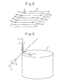
- Fig. 4 is an explanatory diagram of a method of generating a provisional processing program by assigning an edge line to the work shape image 6'.
- the assigning unit 101 such as a pointing device is used to assign an arc 41 of an edge line to the work shape image 6' on the display unit 104, thereby setting points P1 and P2 at both ends of the arc as teaching points.
- the arc 41 of the edge line connected between the teaching points P1 and P2 is programmed as a processing route.
- points at both ends of the straight line are set as teaching points.
- the assigning unit 101 sequentially assigns an edge line (i.e., a straight line) 43 and an edge line (i.e., a straight line) 44 to set teaching points P4 and P1.
- the provisional processing program generating unit 105 generates a provisional program in which a line that connects between the teaching line P1 and the teaching line P2 is taught as an arc processing route, a line that connects between the teaching point P2 and the teaching point F3 is taught as a straight line route, a line that connects between the teaching point P3 and the teaching point P4 is taught as a straight line route, and a line that connects between the teaching point P4 and the teaching point P1 is taught as a straight line route.
- a processing route is generated by connecting between the teaching points based on the assigned order.
- a vertex is assigned first and another vertex is assigned next, a processing route is generated by connecting between these vertexes with a straight line.
- a processing route of an edge line is generated between both ends of the edge line, and a straight line processing route is generated between a teaching point at one end of the edge line and the assigned vertex.
- an end point of the edge line that is to be connected to the assigned vertex is further assigned as a vertex.
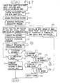
- Fig. 5 is an explanatory diagram of a method of generating a provisional processing program by assigning a surface.
- the input unit 102 assigns a processing start point, and inputs a processing direction, a processing pitch, and a pitch direction.
- a processor of the offline programming device 1 Based on this, a processor of the offline programming device 1 generates a route that moves from a processing start point P1 as a teaching point to the input processing direction.
- a point P2 that is before the cross point of the extension of the route and the edge line of the work by an input pitch amount is taught as an end point of the route.
- a route that moves to the input pitch direction by an input processing pitch amount is formed, and an end point P3 of this route is set as a teaching point.
- a route that moves from this teaching point to a direction opposite to the input processing direction is generated.
- a point P4 that is before the cross point of the extension of the route and the edge line of the work by an input pitch amount is taught as an end point of the route, in the manner as described above. Thereafter, this operation is continued.
- the processing program for processing the surface ends without generating the route that moves by this processing pitch.
- the pointing device is used to assign the processing start point P1 of the image 6' of the work on the display unit 104.
- the teaching points P2, P3, P4, P5, P6, P7, P8, P9, and P10 are sequentially taught.
- the teaching points are sequentially connected with straight lines, thereby generating a processing route.
- Fig. 6 is an explanatory diagram of a method of setting a posture of a processing tool.
- a posture of the processing tool is set at the processing start point (i.e., at the first teaching point).
- the provisional processing program generating unit 105 generates a provisional processing program for processing to the generated processing route in the set posture of the processing tool.
- the posture assigning unit 103 When the posture assigning unit 103 is used to assign the input of a posture of a processing tool, the image of the processing tool is displayed on the screen of the display unit 104.
- the posture of the processing tool can be set while visually observing the posture on the screen.
- a normal line A of a surface formed by the processing route at this teaching point is obtained.
- An angle ⁇ around this normal line A is obtained.
- a tangent B to the processing route is obtained.
- An angle ⁇ around the tangent direction is obtained.
- a normal line C on the surface formed by the tangent B and the normal line A is obtained.
- An angle ⁇ around the normal line C is set. Based on these settings, the posture of the processing tool is determined, and is input.
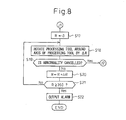
- Fig. 7 and Fig. 8 are flowcharts of the processing program generation processing that the processor of the offline programming device 1 mainly carries out according to the first and the second embodiments.
- the flowcharts shown in Fig. 7 and Fig. 8 are explained below with reference to Fig. 10 and Fig. 11.
- the work shape data generated by the CAD device or the like is read. Further, model data of the robot and model data of a peripheral unit are also read (step S1). Based on the read data, at least the image 6' of the work shape model is displayed on the display screen of the display unit 104 of the offline programming device 1.
- the assigning unit 101 assigns vertexes, an edge line, or a surface to the displayed image 6' of the work shape model to assign a processing part, in the manner as described above (step S2).
- the input unit 102 inputs a processing start point, a processing direction, a processing pitch, and a pitch direction, in the manner as described above.
- the posture assigning unit 103 inputs angles ⁇ , ⁇ , and ⁇ for determining a posture of the processing tool, thereby setting the processing tool posture, in the manner as described above (step S3).
- the processing program generating unit 105 Based on the assigned vertexes, the edge line, or the surface and the input setting data, the processing program generating unit 105 generates a processing route between the teaching points in the input order, thereby generating a provisional processing program that holds a setting processing tool posture to the processing route (step S4).
- the processor of the offline programming device 1 outputs an instruction to the robot control units 2a and 3a to acquire images of the work 6 to be processed, detects a position and a posture of the work 6, and calculates correction data (step S5).
- the following explanation is carried out based on the assumption that the processing program of the robot 2 is generated.
- the robot control unit 2a receives the instruction to acquire images of the work, moves the robot mechanism part 2b to a predetermined imaging position, and outputs an imaging instruction to the image processing unit 4a of the visual sensor 4.
- the image processing unit 4a acquire images of the work with a camera to detect a position and a posture of the work, and transmits data of the image to the offline programming device 1.
- the processor of the offline programming device 1 calculates a deviation between the position and the posture of the work shape model that is input at step S1 and the detected position and the detected posture of the work, and obtains correction data of the coordinate values of each teaching points, in the conventional method.
- the processor obtains correction values of the points of origin and the posture in the coordinate system that represents the position and the posture of the work shape model that is input at step 51 (step S5).
- the actual work processing program generating unit 106 corrects the provisional processing program obtained at step S4, and generates the actual processing program for actually processing the work 6 (step S6).
- An accessing point to the processing starting teaching point and a leaving point from the processing end teaching point are added to the start and the end of the processing program of the corrected processing route, based on the parameters of a speed, a distance, and a direction set in advance. Further, a move instruction from the accessing point to the processing start point and a move instruction from the processing end point to the leaving point are added.
- a processing tool start instruction to start the processing is added to the processing start point, and a processing tool end instruction to end the processing is added to the processing end point.
- Fig. 9a and Fig. 9b are explanatory diagrams of a processing route and a generated processing program.
- Fig. 9a shows a processing route obtained by assigning vertexes and edge lines and by correcting teaching points based on images of the work, where P2 is a processing start point.
- a processing route is generated as follows. An arc route is generated from the processing start point P2 to the teaching points P3 and P4. A straight line route is generated from the teaching point P4 to the teaching point P5. An arc route is generated from the teaching point P5 to the teaching points P6 and P7. A straight line route is generated from the teaching point P7 to the teaching point P8. An arc route is generated from the teaching point P8 to the teaching points P9 and P10.
- a straight line route is generated from the teaching point P10 to the teaching point P11.
- An arc route is generated from the teaching point P11 to the teaching points P12 and P13.
- an accessing point position P1, the processing start point P2, and speed instructions of moves to the accessing point position P1 and the processing start point P2 are added at the beginning.
- Last, a leaving point position P14 and a speed instruction of a move to the leaving point are added.
- a simulation unit 107 further simulates the operation of the generated processing program as shown in Fig. 11.
- Checking units 108, 110, and 112 check presence of abnormality such as the operation, in excess of a stroke limit of each axis of the robot 2 that processes the work, or interference, in the simulated operation of the processing program, and correct the abnormality when it is present. Therefore, prior to the execution of the simulation of the operation of the processing program generated at step S6, the coordinate values of the work shape model, the robot model, and the model of the peripheral unit displayed on the display screen of the display unit 104 are corrected based on the correction data obtained at step S5.
- the simulation unit 107 starts simulating the operation of the processing program (step S7), and detects the presence of an abnormality (step S8).
- the processing program is downloaded to the control unit 2a of the robot 2 (step S10).
- the generation of the processing program ends.
- step S8 the processor decides whether a program change is set valid or invalid (step S11).
- the checking unit 108 decides whether the execution of the program change is selected (YES or NO) (step S12).
- step S13 when the moving of the work is set valid, the checking unit 108 decides whether the execution of the work moving is selected (YES or NO) (step S14).
- the checking unit 108 detects these facts, and makes an alarm unit 109 generate an alarm (step S16) to indicate that the execution of the processing program will cause an occurrence of abnormality.
- the processor executes the processing of step S15.
- the processor outputs a move instruction to move the work from a target position of the processing route in which abnormality occurs (i.e., a front end position of the processing tool on the orthogonal coordinates) to the abnormality occurrence position (i.e., a position on the orthogonal coordinates), and makes the work moving units 3 and 7 move the work 6.
- a target position of the processing route in which abnormality occurs i.e., a front end position of the processing tool on the orthogonal coordinates
- the abnormality occurrence position i.e., a position on the orthogonal coordinates
- step S5 the processing following step S5 is carried out repeatedly.
- the visual sensors 4 and 5 acquire images of the work 6 to obtain correction data.
- the actual work processing program generating unit 106 corrects the provisional processing program based on the correction data, thereby generating the processing program.
- the simulation unit 107 simulates the processing operation of the processing program.
- step S12 when the execution of the changing of the processing program is selected at step S12, "0" is first stored into the register which stores a rotation amount R of the processing tool (step S17).
- a posture adjusting unit 113 rotates the processing tool around the axis of the processing tool (i.e., around a Z axis of the tool coordinate system) by a rotation amount ⁇ R, thereby changing each axial position of the robot and the shape data of the robot (step S18).
- the checking unit 112 decides whether the abnormality is cancelled. In other words, the checking unit 112 decides whether each axis of the robot is within the stroke limit or whether the robot is interfering with other object (such as a peripheral unit and the work) (step S19).
- the posture adjusting unit 113 When the abnormality is not cancelled, the posture adjusting unit 113 adds the ⁇ R to the register that stores the rotation amount R (step S20), and decides whether the rotation amount reaches 360 degrees or above (step S21). When the rotation amount does not reach 360 degrees, the process returns to step S8. The posture adjusting unit 113 rotates the processing tool around the axis of the processing tool by the set rotation amount ⁇ R, and judges whether the abnormality is cancelled. Thereafter, these processing are repeated. When the rotation amount reaches 360 degrees at step S21, the posture adjusting unit 113 decides that the abnormality is not cancelled based on the change of the processing program by changing the posture of the processing tool, and outputs an alarm (step S22), thereby ending the processing.
- step S9 the processing operation of the processing program is simulated.
- step S10 the processing program is downloaded to the robot control units 2a and 3a (step S10). Then, the processing ends.
- the work 6 can be moved by mounting the work on the carriage 7 or by making the robot hold the work 6, thereby correcting the work position.
- a hand can be fitted to the front end of the arm of one robot instead of the processing tool that has been fitted to the front end of the arm.
- the robot fitted with this hand moves the work.
- the processing tool can be fitted to the front end of the arm of the robot again in place of the hand, and the processing can be proceeded.
Landscapes
- Engineering & Computer Science (AREA)
- Robotics (AREA)
- Mechanical Engineering (AREA)
- Numerical Control (AREA)
- Manipulator (AREA)
Applications Claiming Priority (1)
| Application Number | Priority Date | Filing Date | Title |
|---|---|---|---|
| JP2004225977A JP2006048244A (ja) | 2004-08-02 | 2004-08-02 | 加工プログラム作成装置 |
Publications (1)
| Publication Number | Publication Date |
|---|---|
| EP1661669A2 true EP1661669A2 (de) | 2006-05-31 |
Family
ID=35431186
Family Applications (1)
| Application Number | Title | Priority Date | Filing Date |
|---|---|---|---|
| EP05016424A Withdrawn EP1661669A2 (de) | 2004-08-02 | 2005-07-28 | Gerät zur Erzeugung eines Bearbeitungsprogrammes |
Country Status (4)
| Country | Link |
|---|---|
| US (1) | US20060025890A1 (de) |
| EP (1) | EP1661669A2 (de) |
| JP (1) | JP2006048244A (de) |
| CN (1) | CN1734379A (de) |
Families Citing this family (74)
| Publication number | Priority date | Publication date | Assignee | Title |
|---|---|---|---|---|
| SE524818C2 (sv) * | 2003-02-13 | 2004-10-05 | Abb Ab | En metod och ett system för att programmera en industrirobot att förflytta sig relativt definierade positioner på ett objekt |
| JP4266946B2 (ja) * | 2005-03-17 | 2009-05-27 | ファナック株式会社 | オフライン教示装置 |
| JP4056542B2 (ja) * | 2005-09-28 | 2008-03-05 | ファナック株式会社 | ロボットのオフライン教示装置 |
| CN101059689B (zh) * | 2006-04-19 | 2010-09-29 | 未来产业株式会社 | 虚拟装配机系统 |
| DE102006022483A1 (de) | 2006-05-13 | 2007-11-29 | Kuka Roboter Gmbh | Verfahren und Vorrichtung zum Anzeigen einer Roboterbahn zur Unterstützung einer Ortsänderung eines Stützpunktes |
| EP1886771B1 (de) | 2006-05-31 | 2011-04-06 | Panasonic Corporation | Verfahren zur berechnung eines rotationsmittelpunktes, verfahren zur berechnung einer rotationsachse, verfahren zur erstellung eines programms, betriebsverfahren und robotergerät |
| JP4256419B2 (ja) * | 2006-10-05 | 2009-04-22 | ファナック株式会社 | 旋削加工用のプログラム作成装置 |
| JP4298757B2 (ja) * | 2007-02-05 | 2009-07-22 | ファナック株式会社 | ロボット機構のキャリブレーション装置及び方法 |
| US9155452B2 (en) | 2007-04-27 | 2015-10-13 | Intuitive Surgical Operations, Inc. | Complex shape steerable tissue visualization and manipulation catheter |
| DE102008027485B4 (de) | 2008-06-09 | 2010-02-11 | Gsi Helmholtzzentrum Für Schwerionenforschung Gmbh | Deposition einer Solldosisverteilung in einem zyklisch bewegten Zielgebiet |
| DE102008027475A1 (de) * | 2008-06-09 | 2009-12-10 | Kuka Roboter Gmbh | Vorrichtung und Verfahren zur rechnergestützten Generierung einer Manipulatorbahn |
| JP5024905B2 (ja) * | 2009-07-16 | 2012-09-12 | 独立行政法人科学技術振興機構 | 衣料折り畳みシステム、衣料折り畳み指示装置 |
| DE102010004477A1 (de) | 2010-01-13 | 2011-07-14 | KUKA Laboratories GmbH, 86165 | Entwicklungsumgebung und Verfahren zur Planung einer Roboterapplikation |
| EP2345514A3 (de) | 2010-01-13 | 2017-07-19 | KUKA Roboter GmbH | Verfahren und Vorrichtung zum Kontrollieren einer Roboterapplikation |
| JP5715809B2 (ja) * | 2010-03-29 | 2015-05-13 | 株式会社ダイヘン | ロボットの作業プログラム作成方法、ロボットの作業プログラム作成装置、及びロボット制御システム |
| CN101850552A (zh) * | 2010-05-28 | 2010-10-06 | 广东工业大学 | 一种工业机器人综合控制平台及其控制方法 |
| DE102010032917A1 (de) * | 2010-07-30 | 2012-04-19 | Brötje-Automation GmbH | Verfahren zur Offline-Programmierung eines NC-gesteuerten Manipulators |
| DE102011011542B4 (de) * | 2011-02-17 | 2016-05-25 | Convergent Information Technologies Gmbh | Verfahren zur automatisierten Programmierung und Optimierung von robotischen Arbeitsabläufen |
| WO2013037693A2 (de) * | 2011-09-15 | 2013-03-21 | Convergent Information Technologies Gmbh | System und verfahren zur automatisierten erstellung von roboterprogrammen |
| JP5340455B1 (ja) * | 2012-05-30 | 2013-11-13 | ファナック株式会社 | オフラインプログラミング装置 |
| JP2014024162A (ja) * | 2012-07-27 | 2014-02-06 | Seiko Epson Corp | ロボットシステム、ロボット制御装置、ロボット制御方法及びロボット制御プログラム |
| JP5983763B2 (ja) * | 2012-11-30 | 2016-09-06 | 株式会社安川電機 | ロボットシステム |
| DE102012024934B4 (de) * | 2012-12-19 | 2016-03-10 | Audi Ag | Verfahren und Programmiersystem zur erstmaligen Erstellung eines auf einem Messroboter ausführbaren Messprogramms für die Messung eines neuen Messobjekts |
| JP5729404B2 (ja) | 2013-02-21 | 2015-06-03 | 株式会社安川電機 | ティーチングシステムおよびティーチング方法 |
| US9649765B2 (en) | 2013-03-11 | 2017-05-16 | Siemens Aktiengesellschaft | Reducing energy consumption of industrial robots by using new methods for motion path programming |
| JP5845212B2 (ja) | 2013-06-28 | 2016-01-20 | ファナック株式会社 | 視覚センサ及び力センサを備えたバリ取り装置 |
| JP5939213B2 (ja) * | 2013-08-09 | 2016-06-22 | 株式会社安川電機 | ロボット制御装置及びロボット制御方法 |
| JP5975010B2 (ja) * | 2013-10-17 | 2016-08-23 | 株式会社安川電機 | ティーチングシステムおよびティーチング方法 |
| JP5850958B2 (ja) * | 2014-01-24 | 2016-02-03 | ファナック株式会社 | ワークを撮像するためのロボットプログラムを作成するロボットプログラミング装置 |
| US20150277398A1 (en) * | 2014-03-26 | 2015-10-01 | Siemens Industry Software Ltd. | Object manipulation driven robot offline programming for multiple robot system |
| US9922144B2 (en) | 2014-03-26 | 2018-03-20 | Siemens Industry Software Ltd. | Energy and cycle time efficiency based method for robot positioning |
| US9701011B2 (en) | 2014-05-08 | 2017-07-11 | Siemens Industry Software Ltd. | Method for robotic energy saving tool search |
| US10836038B2 (en) | 2014-05-21 | 2020-11-17 | Fanuc America Corporation | Learning path control |
| US9815201B2 (en) | 2014-07-31 | 2017-11-14 | Siemens Industry Software Limited | Method and apparatus for industrial robotic energy saving optimization using fly-by |
| US9298863B2 (en) | 2014-07-31 | 2016-03-29 | Siemens Industry Software Ltd. | Method and apparatus for saving energy and reducing cycle time by using optimal robotic joint configurations |
| US9469029B2 (en) | 2014-07-31 | 2016-10-18 | Siemens Industry Software Ltd. | Method and apparatus for saving energy and reducing cycle time by optimal ordering of the industrial robotic path |
| US9457469B2 (en) * | 2014-08-14 | 2016-10-04 | Siemens Industry Software Ltd. | Method and apparatus for automatic and efficient location generation for cooperative motion |
| EP3012067B1 (de) * | 2014-10-22 | 2023-05-03 | BIESSE S.p.A. | Anlage zum schleifen/endbearbeiten von platten aus holz, metall oder dergleichen |
| CN104678901A (zh) * | 2014-12-31 | 2015-06-03 | 厦门大学 | 一种基于三次样条插值的全自动面罩喷淋装置 |
| JP6497953B2 (ja) * | 2015-02-03 | 2019-04-10 | キヤノン株式会社 | オフライン教示装置、オフライン教示方法及びロボットシステム |
| JP2015134407A (ja) * | 2015-04-30 | 2015-07-27 | ファナック株式会社 | 視覚センサ及び力センサを備えたバリ取り装置 |
| TWI570531B (zh) * | 2015-08-31 | 2017-02-11 | 財團法人工業技術研究院 | 加工異常迴避系統及其加工路徑修正方法 |
| JP2017170531A (ja) * | 2016-03-18 | 2017-09-28 | 第一工業株式会社 | バリ取り装置 |
| CN105690394A (zh) * | 2016-04-21 | 2016-06-22 | 奇弩(北京)科技有限公司 | 机器人动作生成方法 |
| CN106054814B (zh) * | 2016-05-28 | 2018-11-30 | 济宁中科先进技术研究院有限公司 | 基于图像灰度的计算机辅助加工方法 |
| JP2018047509A (ja) * | 2016-09-20 | 2018-03-29 | ファナック株式会社 | ロボットシミュレーション装置 |
| JP2018051692A (ja) * | 2016-09-29 | 2018-04-05 | ファナック株式会社 | オフラインプログラミング用ジョグ支援装置、ジョグ支援方法及びジョグ支援プログラム |
| WO2018072134A1 (en) * | 2016-10-19 | 2018-04-26 | Abb Schweiz Ag | Robot processing path automatic compensation method |
| CN108656106A (zh) * | 2017-03-31 | 2018-10-16 | 宁波Gqy视讯股份有限公司 | 机器人肢体动作的设计方法 |
| JP6538751B2 (ja) | 2017-05-18 | 2019-07-03 | ファナック株式会社 | プログラミング装置及びロボット制御方法 |
| US10403539B2 (en) * | 2017-08-04 | 2019-09-03 | Kawasaki Jukogyo Kabushiki Kaisha | Robot diagnosing method |
| JP7199073B2 (ja) * | 2017-10-20 | 2023-01-05 | 株式会社キーレックス | 垂直多関節ロボットの教示データ作成システム |
| CN108356828B (zh) * | 2018-01-30 | 2021-01-15 | 深圳市圆梦精密技术研究院 | 工件坐标系修正方法 |
| JP6816068B2 (ja) * | 2018-07-06 | 2021-01-20 | ファナック株式会社 | ロボットプログラム生成装置 |
| JP6826076B2 (ja) * | 2018-07-17 | 2021-02-03 | ファナック株式会社 | 自動経路生成装置 |
| CN109500812A (zh) * | 2018-11-13 | 2019-03-22 | 上海智殷自动化科技有限公司 | 一种通过视觉图像实时定位的机器人编程方法 |
| CN109395941B (zh) * | 2018-11-15 | 2020-04-21 | 无锡荣恩科技有限公司 | 喷涂环境下实时调节机器人运行速度的方法 |
| US11836577B2 (en) | 2018-11-27 | 2023-12-05 | Amazon Technologies, Inc. | Reinforcement learning model training through simulation |
| US11455234B2 (en) * | 2018-11-21 | 2022-09-27 | Amazon Technologies, Inc. | Robotics application development architecture |
| US11429762B2 (en) | 2018-11-27 | 2022-08-30 | Amazon Technologies, Inc. | Simulation orchestration for training reinforcement learning models |
| US12412117B2 (en) | 2018-11-27 | 2025-09-09 | Amazon Technologies, Inc. | Simulation modeling exchange |
| CN111482957B (zh) * | 2019-07-12 | 2020-12-29 | 上海智殷自动化科技有限公司 | 一种视觉离线示教仪注册方法 |
| US12147216B2 (en) * | 2019-11-13 | 2024-11-19 | Mitsubishi Electric Corporation | Machining program conversion device, numerical control device, and machining program conversion method |
| WO2021110254A1 (en) * | 2019-12-04 | 2021-06-10 | Abb Schweiz Ag | Method of controlling industrial actuator, control system and actuator system |
| CN111113426A (zh) * | 2019-12-31 | 2020-05-08 | 芜湖哈特机器人产业技术研究院有限公司 | 一种基于cad平台的机器人离线编程系统 |
| JP2021154439A (ja) * | 2020-03-27 | 2021-10-07 | セイコーエプソン株式会社 | 教示方法 |
| JP7004868B1 (ja) * | 2020-07-17 | 2022-02-07 | 三菱電機株式会社 | 数値制御装置および数値制御方法 |
| DE112021003559B4 (de) | 2020-09-15 | 2025-07-24 | Fanuc Corporation | Robotersystem und steuerverfahren |
| JP6846075B1 (ja) | 2020-10-19 | 2021-03-24 | 日本省力機械株式会社 | 加工装置 |
| CN112873166A (zh) * | 2021-01-25 | 2021-06-01 | 之江实验室 | 一种生成机器人肢体动作的方法、装置、电子设备及介质 |
| TW202234184A (zh) * | 2021-02-25 | 2022-09-01 | 日商發那科股份有限公司 | 使用從視覺感測器的輸出得到之三維位置資訊的模擬裝置 |
| JP7658158B2 (ja) * | 2021-05-10 | 2025-04-08 | オムロン株式会社 | シミュレーション情報反映装置、方法、プログラム、及びシステム |
| CN113733085B (zh) * | 2021-08-30 | 2023-04-11 | 三一建筑机器人(西安)研究院有限公司 | 工业机器人离线编程方法及装置 |
| JP7613615B2 (ja) * | 2022-11-25 | 2025-01-15 | Jfeスチール株式会社 | 機械加工システム、軌跡生成方法、及び製品の製造方法 |
Family Cites Families (9)
| Publication number | Priority date | Publication date | Assignee | Title |
|---|---|---|---|---|
| US5608847A (en) * | 1981-05-11 | 1997-03-04 | Sensor Adaptive Machines, Inc. | Vision target based assembly |
| US4675502A (en) * | 1985-12-23 | 1987-06-23 | General Electric Company | Real time tracking control for taught path robots |
| JP2517553B2 (ja) * | 1986-05-22 | 1996-07-24 | 株式会社神戸製鋼所 | ロボツトのオフライン教示方法 |
| US4942538A (en) * | 1988-01-05 | 1990-07-17 | Spar Aerospace Limited | Telerobotic tracker |
| US5380978A (en) * | 1991-07-12 | 1995-01-10 | Pryor; Timothy R. | Method and apparatus for assembly of car bodies and other 3-dimensional objects |
| US5353238A (en) * | 1991-09-12 | 1994-10-04 | Cloos International Inc. | Welding robot diagnostic system and method of use thereof |
| JPH07168617A (ja) * | 1993-06-25 | 1995-07-04 | Matsushita Electric Works Ltd | ロボットのオフライン教示方法 |
| JP3665353B2 (ja) * | 1993-09-14 | 2005-06-29 | ファナック株式会社 | ロボットの教示位置データの3次元位置補正量取得方法及びロボットシステム |
| JPH09222913A (ja) * | 1996-02-20 | 1997-08-26 | Komatsu Ltd | ロボットの教示位置補正装置 |
-
2004
- 2004-08-02 JP JP2004225977A patent/JP2006048244A/ja active Pending
-
2005
- 2005-07-28 EP EP05016424A patent/EP1661669A2/de not_active Withdrawn
- 2005-08-01 CN CN200510088687.XA patent/CN1734379A/zh active Pending
- 2005-08-01 US US11/193,448 patent/US20060025890A1/en not_active Abandoned
Also Published As
| Publication number | Publication date |
|---|---|
| JP2006048244A (ja) | 2006-02-16 |
| US20060025890A1 (en) | 2006-02-02 |
| CN1734379A (zh) | 2006-02-15 |
Similar Documents
| Publication | Publication Date | Title |
|---|---|---|
| EP1661669A2 (de) | Gerät zur Erzeugung eines Bearbeitungsprogrammes | |
| US7376488B2 (en) | Taught position modification device | |
| DE102018213985B4 (de) | Robotersystem | |
| US10401844B2 (en) | Simulator, simulation method, and simulation program | |
| JP3732494B2 (ja) | シミュレーション装置 | |
| JP5815761B2 (ja) | 視覚センサのデータ作成システム及び検出シミュレーションシステム | |
| US8155789B2 (en) | Device, method, program and recording medium for robot offline programming | |
| EP1769891B1 (de) | Offline Lehrgerät für einen Roboter | |
| EP1769890A2 (de) | Gerät zur Robotersimulation | |
| EP1847359A2 (de) | Robotersimulationsvorrichtung | |
| JP6912529B2 (ja) | 視覚誘導ロボットアームの補正方法 | |
| JP3644991B2 (ja) | ロボット−センサシステムにおける座標系結合方法 | |
| JP7281910B2 (ja) | ロボット制御システム | |
| CN110712194A (zh) | 物体检查装置、物体检查系统以及调整检查位置的方法 | |
| US20110046783A1 (en) | Method for training a robot or the like, and device for implementing said method | |
| JP4266946B2 (ja) | オフライン教示装置 | |
| KR20080088165A (ko) | 로봇 캘리브레이션 방법 | |
| JP6568172B2 (ja) | キャリブレーションを行うロボット制御装置、計測システム及びキャリブレーション方法 | |
| DE112022000442T5 (de) | Simulationsvorrichtung mit Verwendung von dreidimensionalen Positionsinformationen, die aus dem Ausgang eines Vision Sensors gewonnen werden | |
| JPH0790494B2 (ja) | 視覚センサのキャリブレ−ション方法 | |
| JPS59229619A (ja) | ロボツトの作業教示システムおよびその使用方法 | |
| JP5573537B2 (ja) | ロボットのティーチングシステム | |
| JPH0299802A (ja) | ハンドアイを用いた視覚センサにおける座標系設定方法 | |
| JP2019072798A (ja) | ロボットシステム、ロボット制御方法、及びロボット教示方法 | |
| JP7188481B2 (ja) | 位置検出装置およびプログラム |
Legal Events
| Date | Code | Title | Description |
|---|---|---|---|
| PUAI | Public reference made under article 153(3) epc to a published international application that has entered the european phase |
Free format text: ORIGINAL CODE: 0009012 |
|
| AK | Designated contracting states |
Kind code of ref document: A2 Designated state(s): AT BE BG CH CY CZ DE DK EE ES FI FR GB GR HU IE IS IT LI LT LU LV MC NL PL PT RO SE SI SK TR |
|
| AX | Request for extension of the european patent |
Extension state: AL BA HR MK YU |
|
| STAA | Information on the status of an ep patent application or granted ep patent |
Free format text: STATUS: THE APPLICATION HAS BEEN WITHDRAWN |
|
| 18W | Application withdrawn |
Effective date: 20080424 |