EP1660737B1 - Befestigungseinrichtung zur herstellung einer verankerung in insbesondere aus glas bestehenden platten - Google Patents
Befestigungseinrichtung zur herstellung einer verankerung in insbesondere aus glas bestehenden platten Download PDFInfo
- Publication number
- EP1660737B1 EP1660737B1 EP04764440A EP04764440A EP1660737B1 EP 1660737 B1 EP1660737 B1 EP 1660737B1 EP 04764440 A EP04764440 A EP 04764440A EP 04764440 A EP04764440 A EP 04764440A EP 1660737 B1 EP1660737 B1 EP 1660737B1
- Authority
- EP
- European Patent Office
- Prior art keywords
- anchor bolt
- fixing device
- glass
- anchoring
- covering
- Prior art date
- Legal status (The legal status is an assumption and is not a legal conclusion. Google has not performed a legal analysis and makes no representation as to the accuracy of the status listed.)
- Expired - Lifetime
Links
Images
Classifications
-
- E—FIXED CONSTRUCTIONS
- E04—BUILDING
- E04F—FINISHING WORK ON BUILDINGS, e.g. STAIRS, FLOORS
- E04F13/00—Coverings or linings, e.g. for walls or ceilings
- E04F13/07—Coverings or linings, e.g. for walls or ceilings composed of covering or lining elements; Sub-structures therefor; Fastening means therefor
- E04F13/08—Coverings or linings, e.g. for walls or ceilings composed of covering or lining elements; Sub-structures therefor; Fastening means therefor composed of a plurality of similar covering or lining elements
-
- E—FIXED CONSTRUCTIONS
- E04—BUILDING
- E04F—FINISHING WORK ON BUILDINGS, e.g. STAIRS, FLOORS
- E04F13/00—Coverings or linings, e.g. for walls or ceilings
- E04F13/07—Coverings or linings, e.g. for walls or ceilings composed of covering or lining elements; Sub-structures therefor; Fastening means therefor
- E04F13/08—Coverings or linings, e.g. for walls or ceilings composed of covering or lining elements; Sub-structures therefor; Fastening means therefor composed of a plurality of similar covering or lining elements
- E04F13/0801—Separate fastening elements
- E04F13/0832—Separate fastening elements without load-supporting elongated furring elements between wall and covering elements
- E04F13/0833—Separate fastening elements without load-supporting elongated furring elements between wall and covering elements not adjustable
- E04F13/0835—Separate fastening elements without load-supporting elongated furring elements between wall and covering elements not adjustable the fastening elements extending into the back side of the covering elements
-
- E—FIXED CONSTRUCTIONS
- E04—BUILDING
- E04F—FINISHING WORK ON BUILDINGS, e.g. STAIRS, FLOORS
- E04F13/00—Coverings or linings, e.g. for walls or ceilings
- E04F13/07—Coverings or linings, e.g. for walls or ceilings composed of covering or lining elements; Sub-structures therefor; Fastening means therefor
- E04F13/08—Coverings or linings, e.g. for walls or ceilings composed of covering or lining elements; Sub-structures therefor; Fastening means therefor composed of a plurality of similar covering or lining elements
- E04F13/0801—Separate fastening elements
- E04F13/0803—Separate fastening elements with load-supporting elongated furring elements between wall and covering elements
- E04F13/081—Separate fastening elements with load-supporting elongated furring elements between wall and covering elements with additional fastening elements between furring elements and covering elements
- E04F13/0816—Separate fastening elements with load-supporting elongated furring elements between wall and covering elements with additional fastening elements between furring elements and covering elements the additional fastening elements extending into the back side of the covering elements
-
- E—FIXED CONSTRUCTIONS
- E04—BUILDING
- E04F—FINISHING WORK ON BUILDINGS, e.g. STAIRS, FLOORS
- E04F13/00—Coverings or linings, e.g. for walls or ceilings
- E04F13/07—Coverings or linings, e.g. for walls or ceilings composed of covering or lining elements; Sub-structures therefor; Fastening means therefor
- E04F13/08—Coverings or linings, e.g. for walls or ceilings composed of covering or lining elements; Sub-structures therefor; Fastening means therefor composed of a plurality of similar covering or lining elements
- E04F13/14—Coverings or linings, e.g. for walls or ceilings composed of covering or lining elements; Sub-structures therefor; Fastening means therefor composed of a plurality of similar covering or lining elements stone or stone-like materials, e.g. ceramics concrete; of glass or with an outer layer of stone or stone-like materials or glass
- E04F13/145—Coverings or linings, e.g. for walls or ceilings composed of covering or lining elements; Sub-structures therefor; Fastening means therefor composed of a plurality of similar covering or lining elements stone or stone-like materials, e.g. ceramics concrete; of glass or with an outer layer of stone or stone-like materials or glass with an outer layer of glass
-
- E—FIXED CONSTRUCTIONS
- E04—BUILDING
- E04F—FINISHING WORK ON BUILDINGS, e.g. STAIRS, FLOORS
- E04F13/00—Coverings or linings, e.g. for walls or ceilings
- E04F13/07—Coverings or linings, e.g. for walls or ceilings composed of covering or lining elements; Sub-structures therefor; Fastening means therefor
- E04F13/08—Coverings or linings, e.g. for walls or ceilings composed of covering or lining elements; Sub-structures therefor; Fastening means therefor composed of a plurality of similar covering or lining elements
- E04F13/14—Coverings or linings, e.g. for walls or ceilings composed of covering or lining elements; Sub-structures therefor; Fastening means therefor composed of a plurality of similar covering or lining elements stone or stone-like materials, e.g. ceramics concrete; of glass or with an outer layer of stone or stone-like materials or glass
- E04F13/15—Coverings or linings, e.g. for walls or ceilings composed of covering or lining elements; Sub-structures therefor; Fastening means therefor composed of a plurality of similar covering or lining elements stone or stone-like materials, e.g. ceramics concrete; of glass or with an outer layer of stone or stone-like materials or glass characterised by the use of glass elements, i.e. wherein an outer layer is not of glass
-
- E—FIXED CONSTRUCTIONS
- E06—DOORS, WINDOWS, SHUTTERS, OR ROLLER BLINDS IN GENERAL; LADDERS
- E06B—FIXED OR MOVABLE CLOSURES FOR OPENINGS IN BUILDINGS, VEHICLES, FENCES OR LIKE ENCLOSURES IN GENERAL, e.g. DOORS, WINDOWS, BLINDS, GATES
- E06B3/00—Window sashes, door leaves, or like elements for closing wall or like openings; Layout of fixed or moving closures, e.g. windows in wall or like openings; Features of rigidly-mounted outer frames relating to the mounting of wing frames
- E06B3/54—Fixing of glass panes or like plates
- E06B3/5436—Fixing of glass panes or like plates involving holes or indentations in the pane
-
- F—MECHANICAL ENGINEERING; LIGHTING; HEATING; WEAPONS; BLASTING
- F16—ENGINEERING ELEMENTS AND UNITS; GENERAL MEASURES FOR PRODUCING AND MAINTAINING EFFECTIVE FUNCTIONING OF MACHINES OR INSTALLATIONS; THERMAL INSULATION IN GENERAL
- F16B—DEVICES FOR FASTENING OR SECURING CONSTRUCTIONAL ELEMENTS OR MACHINE PARTS TOGETHER, e.g. NAILS, BOLTS, CIRCLIPS, CLAMPS, CLIPS OR WEDGES; JOINTS OR JOINTING
- F16B13/00—Dowels or other devices fastened in walls or the like by inserting them in holes made therein for that purpose
- F16B13/14—Non-metallic plugs or sleeves; Use of liquid, loose solid or kneadable material therefor
-
- F—MECHANICAL ENGINEERING; LIGHTING; HEATING; WEAPONS; BLASTING
- F16—ENGINEERING ELEMENTS AND UNITS; GENERAL MEASURES FOR PRODUCING AND MAINTAINING EFFECTIVE FUNCTIONING OF MACHINES OR INSTALLATIONS; THERMAL INSULATION IN GENERAL
- F16B—DEVICES FOR FASTENING OR SECURING CONSTRUCTIONAL ELEMENTS OR MACHINE PARTS TOGETHER, e.g. NAILS, BOLTS, CIRCLIPS, CLAMPS, CLIPS OR WEDGES; JOINTS OR JOINTING
- F16B13/00—Dowels or other devices fastened in walls or the like by inserting them in holes made therein for that purpose
- F16B13/14—Non-metallic plugs or sleeves; Use of liquid, loose solid or kneadable material therefor
- F16B13/141—Fixing plugs in holes by the use of settable material
-
- F—MECHANICAL ENGINEERING; LIGHTING; HEATING; WEAPONS; BLASTING
- F16—ENGINEERING ELEMENTS AND UNITS; GENERAL MEASURES FOR PRODUCING AND MAINTAINING EFFECTIVE FUNCTIONING OF MACHINES OR INSTALLATIONS; THERMAL INSULATION IN GENERAL
- F16B—DEVICES FOR FASTENING OR SECURING CONSTRUCTIONAL ELEMENTS OR MACHINE PARTS TOGETHER, e.g. NAILS, BOLTS, CIRCLIPS, CLAMPS, CLIPS OR WEDGES; JOINTS OR JOINTING
- F16B11/00—Connecting constructional elements or machine parts by sticking or pressing them together, e.g. cold pressure welding
- F16B11/006—Connecting constructional elements or machine parts by sticking or pressing them together, e.g. cold pressure welding by gluing
-
- F—MECHANICAL ENGINEERING; LIGHTING; HEATING; WEAPONS; BLASTING
- F16—ENGINEERING ELEMENTS AND UNITS; GENERAL MEASURES FOR PRODUCING AND MAINTAINING EFFECTIVE FUNCTIONING OF MACHINES OR INSTALLATIONS; THERMAL INSULATION IN GENERAL
- F16B—DEVICES FOR FASTENING OR SECURING CONSTRUCTIONAL ELEMENTS OR MACHINE PARTS TOGETHER, e.g. NAILS, BOLTS, CIRCLIPS, CLAMPS, CLIPS OR WEDGES; JOINTS OR JOINTING
- F16B13/00—Dowels or other devices fastened in walls or the like by inserting them in holes made therein for that purpose
- F16B2013/007—Dowels or other devices fastened in walls or the like by inserting them in holes made therein for that purpose to be fastened in undercut holes
-
- F—MECHANICAL ENGINEERING; LIGHTING; HEATING; WEAPONS; BLASTING
- F16—ENGINEERING ELEMENTS AND UNITS; GENERAL MEASURES FOR PRODUCING AND MAINTAINING EFFECTIVE FUNCTIONING OF MACHINES OR INSTALLATIONS; THERMAL INSULATION IN GENERAL
- F16B—DEVICES FOR FASTENING OR SECURING CONSTRUCTIONAL ELEMENTS OR MACHINE PARTS TOGETHER, e.g. NAILS, BOLTS, CIRCLIPS, CLAMPS, CLIPS OR WEDGES; JOINTS OR JOINTING
- F16B37/00—Nuts or like thread-engaging members
- F16B37/04—Devices for fastening nuts to surfaces, e.g. sheets, plates
- F16B37/048—Non-releasable devices
Definitions
- the invention relates to a fastening device for producing an anchoring in particular made of glass plates having the features of the preamble of claim 1.
- a fastener which serves in particular the attachment of glass plates. It consists of an anchor bolt and a spreader, wherein the spreader is anchored by pulling and / or pushing on the expansion cone of the anchor bolt in a drilled hole having an undercut. Between the spreader and the wall of the undercut borehole a pressing element made of soft plastic is arranged. This ensures that the holding forces do not lead to high point loads in the borehole, as could not be excluded in direct contact between metal and glass.
- the publication US 5,787,662 shows a component for the glazing of buildings with glass panels made of laminated safety glass using a holding element.
- the holding element has a lower and an upper support plate with a neoprene ring on which the laminated glass rests.
- the glass sheet has a through hole through which a threaded bolt with a surrounding sleeve is performed.
- the annular gap between glass and sleeve is filled with a flowable, hardenable plastic.
- EP-A-0314120 discloses the preamble of claim 1.
- the invention is therefore based on the object to provide a suitable in particular for the attachment of glass plates fastening device having an increased elasticity.
- the fastening device does not provide anchoring by means of bracing but by means of a hardenable mass, for example an epoxy resin, polyester resin or a mortar.
- the anchor bolt is surrounded in the region of the anchoring section with a sheath made of an elastic plastic. This provides for an elasticity of the fastener in all directions, whereby a skewing of the anchor bolt relative to the plate is possible.
- this ensures that the anchor bolt touches the borehole wall at any point. Such contact could occur without the shroud, for example, due to an eccentric position of the anchor bolt or landing on the bottom of the well during the curing of the mass. While such touches can lead to the mentioned point loads, an elastic sheath ensures a flat distribution.
- the elasticity of the fastening device can be controlled on the one hand by the thickness and on the other hand by the modulus of elasticity of the plastic used.
- the thickness of the sheath is chosen so that the smallest outer diameter of the sheath is less than the maximum diameter of the sheath Anchoring portion of the anchor bolt is. This ensures that the anchor bolt can not be pulled out of the borehole by merely shearing the casing along a cylindrical surface.
- the sheath contains silicone as an ingredient because it has been found to be suitable as a durable, permanently elastic material for this application.
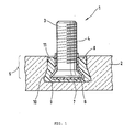
- the fastening element has an anchor bolt 3 with an external thread 4 as a fastening means and an anchoring portion 5 with a conical cross-sectional widening 6 in the insertion direction. On the external thread 4, for example, by means of nuts, washers or the like.
- the connection to a supporting structure done (not shown).
- the anchoring section 5 has a silicone-containing sheath 7, which is surrounded by a hardened mass 8.
- the borehole 9 has a conical undercut 10, which prevents the hardened mass 8 from being pulled out of the borehole 9 by detachment from the borehole wall 11.
- the thickness of the casing 7 is selected so that the cross-sectional widening 6 of the anchoring portion 5 forms an undercut in the hardened mass 8 independently of the casing. This ensures that the anchor bolt 3 can not be pulled out of the hardened mass 8 even with complete displacement of the sheath 7. Nevertheless, elastic displacements in all directions of about twice the thickness of the sheath and an inclination of about 10 degrees are possible.
- the mass 8 is first introduced after the creation of the undercut borehole 9. Before this cures, the anchor bolt 3 is inserted into the wellbore 9. As a result, the mass 8 is displaced and distributed around the anchor bolt 3. Here, a central positioning is not necessary. However, if this is desirable for reasons of a precise connection to a supporting structure, the sheath 7 can additionally at its end facing away from the anchoring portion 5 a circumferential collar, ribs or the like. (Not shown), which provides for a centering and / or an axial stop at the wellbore 9.
Landscapes
- Engineering & Computer Science (AREA)
- Architecture (AREA)
- Civil Engineering (AREA)
- Structural Engineering (AREA)
- General Engineering & Computer Science (AREA)
- Chemical & Material Sciences (AREA)
- Mechanical Engineering (AREA)
- Ceramic Engineering (AREA)
- Dowels (AREA)
- Glass Compositions (AREA)
- Securing Of Glass Panes Or The Like (AREA)
- Joining Of Building Structures In Genera (AREA)
- Joining Of Glass To Other Materials (AREA)
- Load-Bearing And Curtain Walls (AREA)
- Piles And Underground Anchors (AREA)
Description
- Die Erfindung betrifft eine Befestigungseinrichtung zur Herstellung einer Verankerung in insbesondere aus Glas bestehenden Platten mit den Merkmalen des Oberbegriffs des Anspruchs 1.
- Aus der Druckschrift
DE 43 34 286 C2 ist ein Befestigungselement bekannt, das insbesondere der Befestigung von Glasplatten dient. Es besteht aus einem Ankerbolzen und einem Spreizelement, wobei das Spreizelement durch Einziehen und/oder Aufschieben auf den Spreizkonus des Ankerbolzens in einem eine Hinterschneidung aufweisenden Bohrloch verankerbar ist. Zwischen dem Spreizelement und der Wandung des hinterschnittenen Bohrloches ist ein Presselement aus weichem Kunststoff angeordnet. Hierdurch wird erreicht, dass die Haltekräfte nicht zu hohen Punktlasten im Bohrloch führen, wie dies bei direktem Kontakt zwischen Metall und Glas nicht auszuschließen wäre. - Die Druckschrift
US 5 787 662 zeigt ein Bauelement für die Verglasung von Bauten mit Glastafeln aus Verbundsicherheitsglas unter Verwendung eines Halteelements. Das Halteelement weist einen unteren und einen oberen Auflageteller mit einem Neoprenring auf, an denen die Verbundglasscheibe aufliegt. Die Glasscheibe weist eine Durchgangsbohrung auf, durch die ein Gewindebolzen mit einer umgebenden Hülse durchgeführt ist. Der Ringspalt zwischen Glas und Hülse ist mit einem fließfähigen, aushärtbaren Kunststoff ausgefüllt.
EP-A-0314120 offenbart der Oberbegriff gemäß Anspruch 1. - Problematisch an derartigen Verankerungen ist, dass sie wenig Nachgiebigkeit aufweisen. Insbesondere während der Aufhängung und durch thermisch bedingte Längenänderungen im eingebauten Zustand kann es zu erheblichen Querkräften und Biegemomenten kommen, wenn dem nicht durch aufwändige Maßnahmen, beispielsweise im Bereich des Tragwerks, entgegengewirkt wird.
- Der Erfindung liegt daher die Aufgabe zu Grunde, eine insbesondere für die Befestigung von Glasplatten geeignete Befestigungseinrichtung zu schaffen, die eine erhöhte Elastizität aufweist.
- Diese Aufgabe wird erfindungsgemäß durch die Merkmale des Anspruchs 1 gelöst. Die erfindungsgemäße Befestigungseinrichtung sieht keine Verankerung mittels Verspreizen sondern mittels einer aushärtbaren Masse vor, beispielsweise einem Epoxydharz, Polyesterharz oder einem Mörtel. Der Ankerbolzen ist im Bereich des Verankerungsabschnitts mit einer Ummantelung aus einem elastischen Kunststoff umgeben. Dies sorgt für eine Elastizität des Befestigungselements in alle Richtungen, wodurch eine Schrägstellung des Ankerbolzens gegenüber der Platte möglich ist. Außerdem wird hierdurch erreicht, dass der Ankerbolzen an keiner Stelle die Bohrlochwand berührt. Eine solche Berührung könnte ohne die Ummantelung beispielsweise durch eine außermittige Lage des Ankerbolzens oder ein Aufsetzen auf dem Bohrlochgrund während des Aushärtens der Masse auftreten. Während derartige Berührungen zu den erwähnten Punktlasten führen können, sichert eine elastische Umhüllung eine flächige Verteilung.
- Entscheidend für die erreichbaren Haltewerte der Befestigung ist neben der Auslegung des Ankerbolzens insbesondere die Geometrie des Bohrlochs. Damit eine aushärtbare Masse in einem Bohrloch eine sichere Verbindung eingehen kann, muss es neben adhesiven Wirkungen zu einer formschlüssigen Verbindung kommen. Gerade bei den typischerweise diamantgebohrten Bohrlöchern in Glas ergeben sich aufgrund der sehr glatten Oberfläche bei zylindrischen Bohrlöchern keinerlei hierzu geeignete Hinterschneidungen. Daher muss mittels eines Ausschwenkens des Bohrers oder dgl. eigens eine Hinterschneidung eingebracht werden. Ohne den Erfindungsgedanken zu verlassen, können diese Hinterschneidungen aber auch die Form von unregelmäßigen Riefen, umlaufenden Rillen oder jeglicher Art von Rauigkeit aufweisen.
- Die Elastizität der Befestigungseinrichtung kann einerseits durch die Dicke und andererseits durch den Elastizitätsmodul des verwendeten Kunststoffs gesteuert werden. Je breiter die Ummantelung ist, desto größer sind die ausgleichbaren Verschiebungen, die beispielsweise durch thermische Dehnungen verursacht werden. Vorzugsweise ist die Dicke der Ummantelung jedoch so gewählt, dass der kleinste Außendurchmesser der Ummantelung geringer als der maximale Durchmesser des Verankerungsabschnitts des Ankerbolzens ist. Hierdurch wird erreicht, dass der Ankerbolzen nicht durch reines Abscheren der Ummantelung entlang einer Zylinderfläche aus dem Bohrloch gezogen werden kann.
- Zweckmäßigerweise enthalt die Ummantelung als einen Bestandteil Silikon, da dieses sich als widerstandsfähiges, dauerelastisches Material für diese Anwendung als geeignet herausgestellt hat.
- Die Erfindung wird nachfolgend anhand eines in der Zeichnung dargestellten Ausführungsbeispiels näher erläutert. Die Figur zeigt in einer Schnittdarstellung eine erfindungsgemäße Befestigungseinrichtung 1 zur Befestigung einer Glasplatte 2. Das Befestigungselement weist einen Ankerbolzen 3 mit einem Außengewinde 4 als Befestigungsmittel sowie einem Verankerungsabschnitt 5 mit einer konischen Querschnittsaufweitung 6 in Einbringrichtung auf. An dem Außengewinde 4 kann beispielsweise mit Hilfe von Muttern, Unterlegscheiben oder dgl. die Anbindung an ein Tragwerk erfolgen (nicht dargestellt). Der Verankerungsabschnitt 5 weist eine silikonhaltigen Ummantelung 7 auf, die von einer ausgehärteten Masse 8 umgeben ist. Das Bohrloch 9 weist eine konische Hinterschneidung 10 auf, die verhindert, dass die ausgehärtete Masse 8 durch Ablösung von der Bohrlochwand 11 aus dem Bohrloch 9 gezogen werden kann. Die Dicke der Ummantelung 7 ist so gewählt, dass die Querschnittsaufweitung 6 des Verankerungsabschnitts 5 unabhängig von der Ummantelung einen Hinterschnitt in der ausgehärteten Masse 8 bildet. Hierdurch wird erreicht, dass der Ankerbolzen 3 selbst bei vollständiger Verdrängung der Ummantelung 7 nicht aus der ausgehärteten Masse 8 gezogen werden kann. Dennoch sind elastische Verschiebungen in alle Richtungen von etwa der doppelten Dicke der Ummantelung und ein Schrägstellen von etwa 10 Grad möglich.
- Zur Verankerung mittels der Befestigungseinrichtung 1 wird nach der Erstellung des hinterschnittenen Bohrlochs 9 zunächst die Masse 8 eingebracht. Bevor diese aushärtet, wird der Ankerbolzen 3 in das Bohrloch 9 gesteckt. Hierdurch wird die Masse 8 verdrängt und verteilt sich um den Ankerbolzen 3. Dabei ist eine mittige Positionierung nicht notwendig. Falls dies jedoch aus Gründen einer präzisen Anbindung an ein Tragwerk erwünscht ist, kann die Ummantelung 7 zusätzlich an ihrem dem Verankerungsabschnitt 5 abgewandten Ende einen umlaufenden Bund, Rippen oder dgl. (nicht dargestellt) aufweisen, der für eine Zentrierung und/oder einen axialen Anschlag am Bohrloch 9 sorgt.
Claims (3)
- Befestigungseinrichtung (1) zur Herstellung einer Verankerung, mit einer aus Glas bestehenden Platte (2), wobei die Platte (2) ein hinterschnittenes Sackbohrloch (9) aufweist, mit einer aushärtbaren Masse (8) und mit einem Ankerbolzen (3), der Befestigungsmittel (4) und einen Verankerungsabschnitt (5) mit einer Querschnittsaufweitung (6) in Einbringrichtung aufweist, dadurch gekennzeichnet, dass der Ankerbolzen (3) im Bereich des Verankerungsabschnitts (5) vollständig von einer Ummantelung (7) aus einem elastischen Kunststoff umgeben ist, dass auf Grund der Ummantelung (7) eine Schrägstellung des Ankerbolzens (3) gegenüber der Platte (2) möglich ist, und dass der Ankerbolzen (3) mittels der aushärtbaren Masse (8) verankert ist.
- Befestigungseinrichtung nach Anspruch 1, dadurch gekennzeichnet, dass der kleinste Außendurchmesser der Ummantelung (7) kleiner als die Querschnittsaufweitung (6) des Ankerbolzens (3) ist.
- Befestigungseinrichtung nach Anspruch 1, dadurch gekennzeichnet, dass die Ummantelung (7) aus einem silikonhaltigen Kunststoff besteht.
Priority Applications (1)
| Application Number | Priority Date | Filing Date | Title |
|---|---|---|---|
| PL04764440T PL1660737T3 (pl) | 2003-09-04 | 2004-08-25 | Urządzenie mocujące, do wytwarzania zakotwienia w płytach, zwłaszcza ze szkła |
Applications Claiming Priority (2)
| Application Number | Priority Date | Filing Date | Title |
|---|---|---|---|
| DE10340720A DE10340720A1 (de) | 2003-09-04 | 2003-09-04 | Befestigungseinrichtung zur Herstellung einer Verankerung in insbesondere aus Glas bestehenden Platten |
| PCT/EP2004/009463 WO2005028777A1 (de) | 2003-09-04 | 2004-08-25 | Befestigungseinrichtung zur herstellung einer verankerung in insbesondere aus glas bestehenden platten |
Publications (2)
| Publication Number | Publication Date |
|---|---|
| EP1660737A1 EP1660737A1 (de) | 2006-05-31 |
| EP1660737B1 true EP1660737B1 (de) | 2009-07-29 |
Family
ID=34258394
Family Applications (1)
| Application Number | Title | Priority Date | Filing Date |
|---|---|---|---|
| EP04764440A Expired - Lifetime EP1660737B1 (de) | 2003-09-04 | 2004-08-25 | Befestigungseinrichtung zur herstellung einer verankerung in insbesondere aus glas bestehenden platten |
Country Status (8)
| Country | Link |
|---|---|
| US (1) | US7686552B2 (de) |
| EP (1) | EP1660737B1 (de) |
| KR (1) | KR100767324B1 (de) |
| CN (1) | CN100467817C (de) |
| AT (1) | ATE438002T1 (de) |
| DE (2) | DE10340720A1 (de) |
| PL (1) | PL1660737T3 (de) |
| WO (1) | WO2005028777A1 (de) |
Families Citing this family (14)
| Publication number | Priority date | Publication date | Assignee | Title |
|---|---|---|---|---|
| DE10336359B4 (de) * | 2003-08-08 | 2007-01-04 | Saint-Gobain Glass Deutschland Gmbh | Plattenförmiges Verbundelement mit einer Lagesicherung für eine Klebeverbindung |
| FR2901330B1 (fr) * | 2006-05-22 | 2010-10-29 | Saint Gobain | Systemes de connexion destines a equiper des plaques, notamment en verre, en vue de leur fixation et les plaques ainsi equipees |
| DE102007013433A1 (de) * | 2006-12-10 | 2008-06-12 | Atn Applikationstechnik Neugersdorf Gmbh | Befestigungssystem für die Montage von Bauteilen und Baugruppen und ein Montageverfahren, insbesondere zur Befestigung von Sitzen in Fahrzeugen |
| US8584421B2 (en) * | 2008-11-14 | 2013-11-19 | 3Form, Inc. | Panel mounting components, systems, and methods |
| DE202010016166U1 (de) * | 2010-12-03 | 2012-03-05 | Jungheinrich Aktiengesellschaft | Kettenbolzen zur Verbindung mit einer Hubkette eines Flurförderzeugs |
| EP2570684B1 (de) * | 2011-09-19 | 2015-12-16 | Magna Steyr Fahrzeugtechnik AG & Co KG | Verfahren zur Verbindung eines ersten Bauteils mit einem zweiten Bauteil |
| DE102011085058A1 (de) * | 2011-10-24 | 2013-04-25 | Hilti Aktiengesellschaft | Verbundanker |
| US20130140966A1 (en) * | 2011-12-06 | 2013-06-06 | Htc Corporation | Mobile devices with mechanically bonded connector assemblies and methods for forming such mobile devices |
| US9097017B1 (en) * | 2012-11-04 | 2015-08-04 | Hector Vanlennep | Easy fit concealed post anchor system |
| KR101629660B1 (ko) * | 2013-04-12 | 2016-06-14 | (주)한테크 | 유리고정용 앵커 |
| EP3102837B1 (de) | 2014-02-05 | 2018-08-29 | Jaroslaw Gruszecki | Anker für laminiertes glas und verfahren zum setzen des ankers in laminiertem glas |
| US10502250B2 (en) * | 2016-01-19 | 2019-12-10 | The Boeing Company | Methods and systems for slot joining using slot cases |
| US10562274B1 (en) | 2016-02-22 | 2020-02-18 | Apple Inc. | Glass fastening and sealing systems |
| IT202100000911A1 (it) * | 2021-01-20 | 2022-07-20 | La Tecnica Nel Vetro S P A | Componente di facciata strutturale in vetro-alluminio |
Citations (2)
| Publication number | Priority date | Publication date | Assignee | Title |
|---|---|---|---|---|
| US4642964A (en) * | 1984-09-27 | 1987-02-17 | Kellison Roger C | Grout in place fastener system |
| EP0352226A2 (de) * | 1988-07-08 | 1990-01-24 | HILTI Aktiengesellschaft | Ankerstange |
Family Cites Families (28)
| Publication number | Priority date | Publication date | Assignee | Title |
|---|---|---|---|---|
| US846493A (en) * | 1906-04-09 | 1907-03-12 | Francis T Mallon | Means for securing portraits and other tablets to walls. |
| US3309123A (en) * | 1963-05-21 | 1967-03-14 | Thermal Syndicate Ltd | Attachment of inserts and fixing devices to pieces of vitreous silica, glass and such material |
| GB8504275D0 (en) * | 1985-02-19 | 1985-03-20 | Pilkington Glass Ltd | Sealed double glazing unit |
| FR2580342B1 (fr) * | 1985-04-16 | 1988-05-13 | Dutton Hugh | Attache mecanique de materiaux en plaques a une structure de support vertical desdits materiaux |
| DE8701693U1 (de) * | 1987-02-05 | 1987-04-02 | Flachglas AG, 8510 Fürth | Fassadenplatte in Form einer Verbundglasscheibe |
| DE3708764C2 (de) * | 1987-03-18 | 1995-07-13 | Upat Max Langensiepen Kg | Ankerstange für einen Kunstharzklebeanker |
| DE3716703A1 (de) * | 1987-05-19 | 1988-12-01 | Hilti Ag | Verbundanker mit elektrischer isolation |
| DE3737081A1 (de) | 1987-10-30 | 1989-05-11 | Koller Metallbau Ag | Fassadenkonstruktion fuer hochbauten |
| AU593725B2 (en) * | 1988-03-16 | 1989-09-21 | Flachglas Aktiengesellschaft | Facade panel in the form of a composite glass plate |
| DE4001297A1 (de) * | 1990-01-18 | 1991-07-25 | Fischer Artur Werke Gmbh | Befestigung fuer fassadenplatten |
| DK0440896T3 (da) * | 1990-01-30 | 1994-02-28 | Fischer Artur Werke Gmbh | Fastgørelseselement |
| DE4121620A1 (de) * | 1991-06-29 | 1993-01-07 | Fischer Artur Werke Gmbh | Ankerstange zur verankerung mittels kunstharz |
| DE4221853A1 (de) * | 1992-05-18 | 1993-11-25 | Fischer Artur Werke Gmbh | Anker zur Verankerung mittels einer Verbundmasse in einem Bohrloch eines Betonteils |
| DE4223694C2 (de) * | 1992-07-21 | 1994-05-26 | Danz Robert | Konstruktions-Bauelement für die Verglasung von Bauten |
| EP0608063B1 (de) * | 1993-01-21 | 1998-06-03 | Pilkington United Kingdom Limited | Gerahmte Verglasungseinheit |
| DE4334286C2 (de) * | 1993-10-08 | 2002-09-19 | Fischer Artur Werke Gmbh | Befestigungselement zur Verankerung in insbesondere aus Glas bestehenden Platten |
| FR2713258B1 (fr) * | 1993-11-30 | 1996-02-09 | Saint Gobain Vitrage | Liaison mécanique entre un élément vitré et une structure porteuse. |
| US5490365A (en) * | 1994-05-11 | 1996-02-13 | Roth; Steven A. | Anchor bolt assembly |
| US5562377A (en) * | 1995-04-28 | 1996-10-08 | Giannuzzi; Louis N. | Anchor sleeve and bolt assembly |
| CN1259193A (zh) * | 1997-06-03 | 2000-07-05 | 乌帕特有限公司 | 塑料锚固套 |
| KR100228599B1 (ko) * | 1997-12-26 | 1999-11-01 | 김성만 | 조립용 복층유리 |
| DE19809617C2 (de) * | 1998-03-06 | 2000-05-25 | Brueder Eckelt & Co Glastech | Befestigungseinrichtung für Platten, insbesondere für Glasplatten |
| DE29820560U1 (de) * | 1998-11-18 | 2000-04-06 | fischerwerke Artur Fischer GmbH & Co. KG, 72178 Waldachtal | Klebeanker |
| DE29913278U1 (de) * | 1999-07-29 | 2000-12-07 | fischerwerke Artur Fischer GmbH & Co. KG, 72178 Waldachtal | Befestigungselement für Doppelglasplatten |
| JP2003524715A (ja) * | 1999-10-04 | 2003-08-19 | オーバーホーファー アルフォンス | プレートのための取付け装置 |
| DE20008684U1 (de) * | 2000-05-13 | 2001-09-20 | fischerwerke Artur Fischer GmbH & Co. KG, 72178 Waldachtal | Befestigungselement für ein Mehrscheibenglas und Anordnung in dem in einem plattenförmigen Mehrschichtkörper verankerten Befestigungselement |
| DE10054816B4 (de) * | 2000-07-06 | 2005-09-22 | Saint-Gobain Glass Deutschland Gmbh | Befestigungsanordnung für ein Wandelement in Verbundbauweise und Wandelement |
| KR20020029991A (ko) * | 2000-10-16 | 2002-04-22 | 정명화 | 건축용 유리판넬 및 그 제조방법 |
-
2003
- 2003-09-04 DE DE10340720A patent/DE10340720A1/de not_active Withdrawn
-
2004
- 2004-08-25 AT AT04764440T patent/ATE438002T1/de active
- 2004-08-25 DE DE502004009833T patent/DE502004009833D1/de not_active Expired - Lifetime
- 2004-08-25 CN CNB2004800254303A patent/CN100467817C/zh not_active Expired - Fee Related
- 2004-08-25 KR KR1020067004066A patent/KR100767324B1/ko not_active Expired - Fee Related
- 2004-08-25 US US10/560,456 patent/US7686552B2/en not_active Expired - Fee Related
- 2004-08-25 PL PL04764440T patent/PL1660737T3/pl unknown
- 2004-08-25 EP EP04764440A patent/EP1660737B1/de not_active Expired - Lifetime
- 2004-08-25 WO PCT/EP2004/009463 patent/WO2005028777A1/de not_active Ceased
Patent Citations (2)
| Publication number | Priority date | Publication date | Assignee | Title |
|---|---|---|---|---|
| US4642964A (en) * | 1984-09-27 | 1987-02-17 | Kellison Roger C | Grout in place fastener system |
| EP0352226A2 (de) * | 1988-07-08 | 1990-01-24 | HILTI Aktiengesellschaft | Ankerstange |
Also Published As
| Publication number | Publication date |
|---|---|
| EP1660737A1 (de) | 2006-05-31 |
| CN1846036A (zh) | 2006-10-11 |
| DE502004009833D1 (de) | 2009-09-10 |
| DE10340720A1 (de) | 2005-04-07 |
| ATE438002T1 (de) | 2009-08-15 |
| CN100467817C (zh) | 2009-03-11 |
| KR100767324B1 (ko) | 2007-10-17 |
| US20070071572A1 (en) | 2007-03-29 |
| WO2005028777A1 (de) | 2005-03-31 |
| PL1660737T3 (pl) | 2010-01-29 |
| US7686552B2 (en) | 2010-03-30 |
| KR20060037457A (ko) | 2006-05-03 |
| HK1096441A1 (zh) | 2007-06-01 |
Similar Documents
| Publication | Publication Date | Title |
|---|---|---|
| WO2005028777A1 (de) | Befestigungseinrichtung zur herstellung einer verankerung in insbesondere aus glas bestehenden platten | |
| EP2978911B1 (de) | Bauanordnung und verfahren zum festlegen eines gerüsts an einer gebäudewand | |
| EP2006461B1 (de) | Verfahren zur Befestigung einer Wärmedämmplatte an einer Bauwerksfläche mit einem Befestigungselement | |
| WO1988007141A2 (en) | Fixing rod | |
| EP2715156B1 (de) | System zum befestigen einer dämmfassade und dafür vorgesehener befestiger | |
| EP2722466B1 (de) | Verbundsystem zur Verstärkung von Bauteilen | |
| EP0647760B1 (de) | Befestigungselement zur Verankerung in insbesondere aus Glas bestehenden Platten | |
| DE2838466A1 (de) | Verfahren zum kraftschluessigen verbinden von bauteilen mit mindestens einer ankerhuelse | |
| EP3421678B1 (de) | Verfahren zur anbringung von dämmstoffplatten und befestigungssystem hierfür | |
| DE4126825C1 (en) | Front shuttering securing for facade subsequent repair - drills circular groove in supports shuttering for retaining cylindrical jacket of securing member | |
| EP3138974B1 (de) | Befestigungssystem zur anbringung von dämmstoffplatten oder dergleichen dämmmittel an einen tragenden untergrund | |
| EP1753916A1 (de) | Verankerungsanordnung, ankerstange und verfahren zur herstellung einer verankerungsanordnung | |
| EP2151589B1 (de) | Teleskophülse | |
| DE9400659U1 (de) | Bauelement mit einer Betonplatte und wenigstens einer daran befestigten Steinplatte | |
| DE10214229C5 (de) | Schraubbuchse und Verfahren zur Herstellung eines Verkleidungselements und mit Schraubbuchsen versehenes Verkleidungselement | |
| DE102010061138B4 (de) | Abstandshalter für die Befestigung eines Gegenstands an einem eine Dämmschicht mit einer Putzschicht aufweisenden Untergrund und Befestigungsanordnung mit einem solchem Abstandshalter an einem Untergrund mit Dämmschicht und Putzschicht | |
| DE102007053380B4 (de) | Anordnung aus einem Wärmedämmverbundsystem und einem Gebäudemauerwerk und Verfahren zur Befestigung von Wärmedämmelementen eines Wärmedämmverbundsystems an einem Gebäudemauerwerk | |
| EP1706653A1 (de) | Verankerungsanordnungen und verwendung einer ankerstange | |
| EP4102085A1 (de) | Befestigungssystem zur anbringung von plattenförmigen elementen | |
| EP0670943A1 (de) | Verfahren und anordnung zur befestigung von fassadenplatten. | |
| DE102004030815B4 (de) | Verbindungssystem zur mechanischen Verbindung von Bauelementen | |
| DE4435537C2 (de) | Verankerung für Fertigteile | |
| DE4322089A1 (de) | Verfahren und Anordnung zur Befestigung von Fassadenplatten an Plattenbauwerken | |
| EP3239430A1 (de) | Verfahren zur herstellung eines fassadensystems und vorrichtung zur durchführung des verfahrens | |
| CH466906A (de) | Einrichtung zum Befestigen von plattenförmigen Bauteilen |
Legal Events
| Date | Code | Title | Description |
|---|---|---|---|
| PUAI | Public reference made under article 153(3) epc to a published international application that has entered the european phase |
Free format text: ORIGINAL CODE: 0009012 |
|
| 17P | Request for examination filed |
Effective date: 20051208 |
|
| AK | Designated contracting states |
Kind code of ref document: A1 Designated state(s): AT BE BG CH CY CZ DE DK EE ES FI FR GB GR HU IE IT LI LU MC NL PL PT RO SE SI SK TR |
|
| 17Q | First examination report despatched |
Effective date: 20060718 |
|
| DAX | Request for extension of the european patent (deleted) | ||
| RAP1 | Party data changed (applicant data changed or rights of an application transferred) |
Owner name: FISCHERWERKE GMBH & CO. KG |
|
| GRAP | Despatch of communication of intention to grant a patent |
Free format text: ORIGINAL CODE: EPIDOSNIGR1 |
|
| GRAS | Grant fee paid |
Free format text: ORIGINAL CODE: EPIDOSNIGR3 |
|
| GRAA | (expected) grant |
Free format text: ORIGINAL CODE: 0009210 |
|
| AK | Designated contracting states |
Kind code of ref document: B1 Designated state(s): AT BE BG CH CY CZ DE DK EE ES FI FR GB GR HU IE IT LI LU MC NL PL PT RO SE SI SK TR |
|
| REG | Reference to a national code |
Ref country code: GB Ref legal event code: FG4D Free format text: NOT ENGLISH |
|
| REG | Reference to a national code |
Ref country code: CH Ref legal event code: EP |
|
| REG | Reference to a national code |
Ref country code: IE Ref legal event code: FG4D |
|
| REF | Corresponds to: |
Ref document number: 502004009833 Country of ref document: DE Date of ref document: 20090910 Kind code of ref document: P |
|
| PG25 | Lapsed in a contracting state [announced via postgrant information from national office to epo] |
Ref country code: SE Free format text: LAPSE BECAUSE OF FAILURE TO SUBMIT A TRANSLATION OF THE DESCRIPTION OR TO PAY THE FEE WITHIN THE PRESCRIBED TIME-LIMIT Effective date: 20090729 Ref country code: FI Free format text: LAPSE BECAUSE OF FAILURE TO SUBMIT A TRANSLATION OF THE DESCRIPTION OR TO PAY THE FEE WITHIN THE PRESCRIBED TIME-LIMIT Effective date: 20090729 Ref country code: ES Free format text: LAPSE BECAUSE OF FAILURE TO SUBMIT A TRANSLATION OF THE DESCRIPTION OR TO PAY THE FEE WITHIN THE PRESCRIBED TIME-LIMIT Effective date: 20091109 |
|
| REG | Reference to a national code |
Ref country code: PL Ref legal event code: T3 |
|
| PG25 | Lapsed in a contracting state [announced via postgrant information from national office to epo] |
Ref country code: SI Free format text: LAPSE BECAUSE OF FAILURE TO SUBMIT A TRANSLATION OF THE DESCRIPTION OR TO PAY THE FEE WITHIN THE PRESCRIBED TIME-LIMIT Effective date: 20090729 |
|
| BERE | Be: lapsed |
Owner name: FISCHERWERKE G.M.B.H. & CO. KG Effective date: 20090831 |
|
| REG | Reference to a national code |
Ref country code: IE Ref legal event code: FD4D |
|
| PG25 | Lapsed in a contracting state [announced via postgrant information from national office to epo] |
Ref country code: BG Free format text: LAPSE BECAUSE OF FAILURE TO SUBMIT A TRANSLATION OF THE DESCRIPTION OR TO PAY THE FEE WITHIN THE PRESCRIBED TIME-LIMIT Effective date: 20091029 Ref country code: PT Free format text: LAPSE BECAUSE OF FAILURE TO SUBMIT A TRANSLATION OF THE DESCRIPTION OR TO PAY THE FEE WITHIN THE PRESCRIBED TIME-LIMIT Effective date: 20091129 Ref country code: MC Free format text: LAPSE BECAUSE OF NON-PAYMENT OF DUE FEES Effective date: 20090831 |
|
| PG25 | Lapsed in a contracting state [announced via postgrant information from national office to epo] |
Ref country code: IE Free format text: LAPSE BECAUSE OF FAILURE TO SUBMIT A TRANSLATION OF THE DESCRIPTION OR TO PAY THE FEE WITHIN THE PRESCRIBED TIME-LIMIT Effective date: 20090729 Ref country code: RO Free format text: LAPSE BECAUSE OF FAILURE TO SUBMIT A TRANSLATION OF THE DESCRIPTION OR TO PAY THE FEE WITHIN THE PRESCRIBED TIME-LIMIT Effective date: 20090729 Ref country code: CZ Free format text: LAPSE BECAUSE OF FAILURE TO SUBMIT A TRANSLATION OF THE DESCRIPTION OR TO PAY THE FEE WITHIN THE PRESCRIBED TIME-LIMIT Effective date: 20090729 Ref country code: DK Free format text: LAPSE BECAUSE OF FAILURE TO SUBMIT A TRANSLATION OF THE DESCRIPTION OR TO PAY THE FEE WITHIN THE PRESCRIBED TIME-LIMIT Effective date: 20090729 Ref country code: EE Free format text: LAPSE BECAUSE OF FAILURE TO SUBMIT A TRANSLATION OF THE DESCRIPTION OR TO PAY THE FEE WITHIN THE PRESCRIBED TIME-LIMIT Effective date: 20090729 |
|
| PLBI | Opposition filed |
Free format text: ORIGINAL CODE: 0009260 |
|
| PG25 | Lapsed in a contracting state [announced via postgrant information from national office to epo] |
Ref country code: SK Free format text: LAPSE BECAUSE OF FAILURE TO SUBMIT A TRANSLATION OF THE DESCRIPTION OR TO PAY THE FEE WITHIN THE PRESCRIBED TIME-LIMIT Effective date: 20090729 |
|
| 26 | Opposition filed |
Opponent name: TARDIS GMBH & CO. KG Effective date: 20100429 |
|
| PLAX | Notice of opposition and request to file observation + time limit sent |
Free format text: ORIGINAL CODE: EPIDOSNOBS2 |
|
| PG25 | Lapsed in a contracting state [announced via postgrant information from national office to epo] |
Ref country code: BE Free format text: LAPSE BECAUSE OF NON-PAYMENT OF DUE FEES Effective date: 20090831 |
|
| PLBB | Reply of patent proprietor to notice(s) of opposition received |
Free format text: ORIGINAL CODE: EPIDOSNOBS3 |
|
| PG25 | Lapsed in a contracting state [announced via postgrant information from national office to epo] |
Ref country code: GR Free format text: LAPSE BECAUSE OF FAILURE TO SUBMIT A TRANSLATION OF THE DESCRIPTION OR TO PAY THE FEE WITHIN THE PRESCRIBED TIME-LIMIT Effective date: 20091030 |
|
| PG25 | Lapsed in a contracting state [announced via postgrant information from national office to epo] |
Ref country code: LU Free format text: LAPSE BECAUSE OF NON-PAYMENT OF DUE FEES Effective date: 20090825 |
|
| PG25 | Lapsed in a contracting state [announced via postgrant information from national office to epo] |
Ref country code: HU Free format text: LAPSE BECAUSE OF FAILURE TO SUBMIT A TRANSLATION OF THE DESCRIPTION OR TO PAY THE FEE WITHIN THE PRESCRIBED TIME-LIMIT Effective date: 20100130 |
|
| PLAB | Opposition data, opponent's data or that of the opponent's representative modified |
Free format text: ORIGINAL CODE: 0009299OPPO |
|
| PLAB | Opposition data, opponent's data or that of the opponent's representative modified |
Free format text: ORIGINAL CODE: 0009299OPPO |
|
| R26 | Opposition filed (corrected) |
Opponent name: TARDIS GMBH & CO. KG Effective date: 20100429 |
|
| PG25 | Lapsed in a contracting state [announced via postgrant information from national office to epo] |
Ref country code: TR Free format text: LAPSE BECAUSE OF FAILURE TO SUBMIT A TRANSLATION OF THE DESCRIPTION OR TO PAY THE FEE WITHIN THE PRESCRIBED TIME-LIMIT Effective date: 20090729 |
|
| R26 | Opposition filed (corrected) |
Opponent name: TARDIS GMBH & CO. KG Effective date: 20100429 |
|
| PG25 | Lapsed in a contracting state [announced via postgrant information from national office to epo] |
Ref country code: CY Free format text: LAPSE BECAUSE OF FAILURE TO SUBMIT A TRANSLATION OF THE DESCRIPTION OR TO PAY THE FEE WITHIN THE PRESCRIBED TIME-LIMIT Effective date: 20090729 |
|
| PLCK | Communication despatched that opposition was rejected |
Free format text: ORIGINAL CODE: EPIDOSNREJ1 |
|
| PLBN | Opposition rejected |
Free format text: ORIGINAL CODE: 0009273 |
|
| STAA | Information on the status of an ep patent application or granted ep patent |
Free format text: STATUS: OPPOSITION REJECTED |
|
| 27O | Opposition rejected |
Effective date: 20121005 |
|
| REG | Reference to a national code |
Ref country code: DE Ref legal event code: R100 Ref document number: 502004009833 Country of ref document: DE Effective date: 20121005 |
|
| PGFP | Annual fee paid to national office [announced via postgrant information from national office to epo] |
Ref country code: NL Payment date: 20140820 Year of fee payment: 11 Ref country code: CH Payment date: 20140820 Year of fee payment: 11 |
|
| REG | Reference to a national code |
Ref country code: CH Ref legal event code: PCOW Free format text: NEW ADDRESS: KLAUS-FISCHER-STRASSE 1, 72178 WALDACHTAL (DE) |
|
| PGFP | Annual fee paid to national office [announced via postgrant information from national office to epo] |
Ref country code: PL Payment date: 20140812 Year of fee payment: 11 |
|
| REG | Reference to a national code |
Ref country code: CH Ref legal event code: PL |
|
| PG25 | Lapsed in a contracting state [announced via postgrant information from national office to epo] |
Ref country code: LI Free format text: LAPSE BECAUSE OF NON-PAYMENT OF DUE FEES Effective date: 20150831 Ref country code: CH Free format text: LAPSE BECAUSE OF NON-PAYMENT OF DUE FEES Effective date: 20150831 |
|
| REG | Reference to a national code |
Ref country code: NL Ref legal event code: MM Effective date: 20150901 |
|
| PG25 | Lapsed in a contracting state [announced via postgrant information from national office to epo] |
Ref country code: NL Free format text: LAPSE BECAUSE OF NON-PAYMENT OF DUE FEES Effective date: 20150901 |
|
| REG | Reference to a national code |
Ref country code: FR Ref legal event code: PLFP Year of fee payment: 13 |
|
| PG25 | Lapsed in a contracting state [announced via postgrant information from national office to epo] |
Ref country code: PL Free format text: LAPSE BECAUSE OF NON-PAYMENT OF DUE FEES Effective date: 20150825 |
|
| PGFP | Annual fee paid to national office [announced via postgrant information from national office to epo] |
Ref country code: GB Payment date: 20160819 Year of fee payment: 13 |
|
| PGFP | Annual fee paid to national office [announced via postgrant information from national office to epo] |
Ref country code: FR Payment date: 20160822 Year of fee payment: 13 Ref country code: AT Payment date: 20160822 Year of fee payment: 13 |
|
| REG | Reference to a national code |
Ref country code: AT Ref legal event code: MM01 Ref document number: 438002 Country of ref document: AT Kind code of ref document: T Effective date: 20170825 |
|
| GBPC | Gb: european patent ceased through non-payment of renewal fee |
Effective date: 20170825 |
|
| REG | Reference to a national code |
Ref country code: FR Ref legal event code: ST Effective date: 20180430 |
|
| PG25 | Lapsed in a contracting state [announced via postgrant information from national office to epo] |
Ref country code: AT Free format text: LAPSE BECAUSE OF NON-PAYMENT OF DUE FEES Effective date: 20170825 |
|
| PG25 | Lapsed in a contracting state [announced via postgrant information from national office to epo] |
Ref country code: GB Free format text: LAPSE BECAUSE OF NON-PAYMENT OF DUE FEES Effective date: 20170825 |
|
| PG25 | Lapsed in a contracting state [announced via postgrant information from national office to epo] |
Ref country code: FR Free format text: LAPSE BECAUSE OF NON-PAYMENT OF DUE FEES Effective date: 20170831 |
|
| PGFP | Annual fee paid to national office [announced via postgrant information from national office to epo] |
Ref country code: NL Payment date: 20180724 Year of fee payment: 11 |
|
| PG25 | Lapsed in a contracting state [announced via postgrant information from national office to epo] |
Ref country code: IT Free format text: LAPSE BECAUSE OF NON-PAYMENT OF DUE FEES Effective date: 20190825 |
|
| PGFP | Annual fee paid to national office [announced via postgrant information from national office to epo] |
Ref country code: DE Payment date: 20200523 Year of fee payment: 17 |
|
| REG | Reference to a national code |
Ref country code: DE Ref legal event code: R119 Ref document number: 502004009833 Country of ref document: DE |
|
| PG25 | Lapsed in a contracting state [announced via postgrant information from national office to epo] |
Ref country code: DE Free format text: LAPSE BECAUSE OF NON-PAYMENT OF DUE FEES Effective date: 20220301 |