EP1659835A1 - Hochdruckentladungslampe mit Impulszündvorrichtung und Betriebsverfahren für eine Hochdruckentladungslampe - Google Patents
Hochdruckentladungslampe mit Impulszündvorrichtung und Betriebsverfahren für eine Hochdruckentladungslampe Download PDFInfo
- Publication number
- EP1659835A1 EP1659835A1 EP05024594A EP05024594A EP1659835A1 EP 1659835 A1 EP1659835 A1 EP 1659835A1 EP 05024594 A EP05024594 A EP 05024594A EP 05024594 A EP05024594 A EP 05024594A EP 1659835 A1 EP1659835 A1 EP 1659835A1
- Authority
- EP
- European Patent Office
- Prior art keywords
- discharge lamp
- discharge
- pressure discharge
- lamp
- ignition
- Prior art date
- Legal status (The legal status is an assumption and is not a legal conclusion. Google has not performed a legal analysis and makes no representation as to the accuracy of the status listed.)
- Granted
Links
- 238000000034 method Methods 0.000 title claims abstract description 8
- 239000007858 starting material Substances 0.000 title 1
- 239000003990 capacitor Substances 0.000 claims abstract description 25
- 238000000926 separation method Methods 0.000 claims description 4
- 239000000470 constituent Substances 0.000 abstract 1
- 238000004804 winding Methods 0.000 description 11
- DGAQECJNVWCQMB-PUAWFVPOSA-M Ilexoside XXIX Chemical compound C[C@@H]1CC[C@@]2(CC[C@@]3(C(=CC[C@H]4[C@]3(CC[C@@H]5[C@@]4(CC[C@@H](C5(C)C)OS(=O)(=O)[O-])C)C)[C@@H]2[C@]1(C)O)C)C(=O)O[C@H]6[C@@H]([C@H]([C@@H]([C@H](O6)CO)O)O)O.[Na+] DGAQECJNVWCQMB-PUAWFVPOSA-M 0.000 description 7
- 229910052708 sodium Inorganic materials 0.000 description 7
- 239000011734 sodium Substances 0.000 description 7
- 238000010586 diagram Methods 0.000 description 6
- 238000009792 diffusion process Methods 0.000 description 4
- 229910052751 metal Inorganic materials 0.000 description 4
- 239000002184 metal Substances 0.000 description 4
- 239000011248 coating agent Substances 0.000 description 3
- 238000000576 coating method Methods 0.000 description 3
- 229910052724 xenon Inorganic materials 0.000 description 3
- FHNFHKCVQCLJFQ-UHFFFAOYSA-N xenon atom Chemical compound [Xe] FHNFHKCVQCLJFQ-UHFFFAOYSA-N 0.000 description 3
- ZOKXTWBITQBERF-UHFFFAOYSA-N Molybdenum Chemical compound [Mo] ZOKXTWBITQBERF-UHFFFAOYSA-N 0.000 description 2
- HCHKCACWOHOZIP-UHFFFAOYSA-N Zinc Chemical compound [Zn] HCHKCACWOHOZIP-UHFFFAOYSA-N 0.000 description 2
- 230000015556 catabolic process Effects 0.000 description 2
- 239000011888 foil Substances 0.000 description 2
- 229910052738 indium Inorganic materials 0.000 description 2
- APFVFJFRJDLVQX-UHFFFAOYSA-N indium atom Chemical compound [In] APFVFJFRJDLVQX-UHFFFAOYSA-N 0.000 description 2
- 229910001507 metal halide Inorganic materials 0.000 description 2
- 150000002739 metals Chemical class 0.000 description 2
- 229910052750 molybdenum Inorganic materials 0.000 description 2
- 239000011733 molybdenum Substances 0.000 description 2
- 238000011017 operating method Methods 0.000 description 2
- 229910052706 scandium Inorganic materials 0.000 description 2
- SIXSYDAISGFNSX-UHFFFAOYSA-N scandium atom Chemical compound [Sc] SIXSYDAISGFNSX-UHFFFAOYSA-N 0.000 description 2
- 229910052725 zinc Inorganic materials 0.000 description 2
- 239000011701 zinc Substances 0.000 description 2
- VYPSYNLAJGMNEJ-UHFFFAOYSA-N Silicium dioxide Chemical compound O=[Si]=O VYPSYNLAJGMNEJ-UHFFFAOYSA-N 0.000 description 1
- 230000007423 decrease Effects 0.000 description 1
- 230000001419 dependent effect Effects 0.000 description 1
- 238000010891 electric arc Methods 0.000 description 1
- 239000011521 glass Substances 0.000 description 1
- 150000004820 halides Chemical class 0.000 description 1
- 150000004694 iodide salts Chemical class 0.000 description 1
- 229910052746 lanthanum Inorganic materials 0.000 description 1
- 239000000155 melt Substances 0.000 description 1
- QSHDDOUJBYECFT-UHFFFAOYSA-N mercury Chemical compound [Hg] QSHDDOUJBYECFT-UHFFFAOYSA-N 0.000 description 1
- 229910052753 mercury Inorganic materials 0.000 description 1
- -1 metal halide compounds Chemical class 0.000 description 1
- 150000005309 metal halides Chemical class 0.000 description 1
- 238000007789 sealing Methods 0.000 description 1
- 239000004065 semiconductor Substances 0.000 description 1
- 229910001415 sodium ion Inorganic materials 0.000 description 1
- 230000007704 transition Effects 0.000 description 1
Images


Classifications
-
- H—ELECTRICITY
- H05—ELECTRIC TECHNIQUES NOT OTHERWISE PROVIDED FOR
- H05B—ELECTRIC HEATING; ELECTRIC LIGHT SOURCES NOT OTHERWISE PROVIDED FOR; CIRCUIT ARRANGEMENTS FOR ELECTRIC LIGHT SOURCES, IN GENERAL
- H05B41/00—Circuit arrangements or apparatus for igniting or operating discharge lamps
- H05B41/14—Circuit arrangements
- H05B41/26—Circuit arrangements in which the lamp is fed by power derived from DC by means of a converter, e.g. by high-voltage DC
- H05B41/28—Circuit arrangements in which the lamp is fed by power derived from DC by means of a converter, e.g. by high-voltage DC using static converters
- H05B41/288—Circuit arrangements in which the lamp is fed by power derived from DC by means of a converter, e.g. by high-voltage DC using static converters with semiconductor devices and specially adapted for lamps without preheating electrodes, e.g. for high-intensity discharge lamps, high-pressure mercury or sodium lamps or low-pressure sodium lamps
- H05B41/2881—Load circuits; Control thereof
-
- H—ELECTRICITY
- H05—ELECTRIC TECHNIQUES NOT OTHERWISE PROVIDED FOR
- H05B—ELECTRIC HEATING; ELECTRIC LIGHT SOURCES NOT OTHERWISE PROVIDED FOR; CIRCUIT ARRANGEMENTS FOR ELECTRIC LIGHT SOURCES, IN GENERAL
- H05B41/00—Circuit arrangements or apparatus for igniting or operating discharge lamps
- H05B41/02—Details
- H05B41/04—Starting switches
- H05B41/042—Starting switches using semiconductor devices
-
- Y—GENERAL TAGGING OF NEW TECHNOLOGICAL DEVELOPMENTS; GENERAL TAGGING OF CROSS-SECTIONAL TECHNOLOGIES SPANNING OVER SEVERAL SECTIONS OF THE IPC; TECHNICAL SUBJECTS COVERED BY FORMER USPC CROSS-REFERENCE ART COLLECTIONS [XRACs] AND DIGESTS
- Y02—TECHNOLOGIES OR APPLICATIONS FOR MITIGATION OR ADAPTATION AGAINST CLIMATE CHANGE
- Y02B—CLIMATE CHANGE MITIGATION TECHNOLOGIES RELATED TO BUILDINGS, e.g. HOUSING, HOUSE APPLIANCES OR RELATED END-USER APPLICATIONS
- Y02B20/00—Energy efficient lighting technologies, e.g. halogen lamps or gas discharge lamps
Definitions
- the invention relates to a high-pressure discharge lamp according to the preamble of patent claim 1 and to an operating method for a high-pressure discharge lamp.
- Such a high-pressure discharge lamp is disclosed, for example, in WO 98/18297.
- This publication describes a high-pressure discharge lamp with an auxiliary starting electrode and a pulse ignition device arranged in the lamp base for igniting the gas discharge in the discharge vessel of the high-pressure discharge lamp.
- the pulse ignition device and the operating circuit for the high-pressure discharge lamp are galvanically separated from each other by means of a transformer. Both the pulse ignition device and the operating circuit are connected to their power supply to a secondary winding of the transformer whose primary windings are formed as part of a push-pull inverter.
- the shutdown of the pulse ignition after successful ignition of the gas discharge by means of a semiconductor switch.
- the high-pressure discharge lamp according to the invention has electrodes arranged within its discharge vessel, which define a discharge path, and an ignition device arranged inside its lamp base, designed as a pulse ignition device for igniting the gas discharge in the discharge vessel, and a starting auxiliary electrode arranged outside the discharge vessel, the voltage input of the pulse ignition device being parallel to the discharge path the high-pressure discharge lamp is connected.
- the pulse ignition device can be supplied with energy directly from the voltage drop across the discharge path of the high-pressure discharge lamp. A separate generation of the supply voltage for the ignition device is therefore eliminated.
- no switch for deactivating the pulse ignition device is required after successful ignition of the gas discharge in the lamp, since the voltage drop across the discharge path decreases significantly after ignition of the gas discharge and thus the voltage applied to the pulse ignition device is no longer sufficient to generate Zündnapssimpulsen.
- the starting capacitor of the pulse ignition device is arranged in a direct current path connected in parallel with the discharge path of the high-pressure discharge lamp.
- the charging current for the ignition capacitor is generated directly from the voltage drop across the discharge path of the high-pressure discharge lamp.
- the discharge path is electrically insulating and therefore the starting capacitor is charged to a sufficiently high voltage to enable it to be discharged intermittently over a spark gap or equivalent threshold component and the generation of ignition voltage pulses by means of the ignition transformer and auxiliary starting electrode.
- the discharge path of the high-pressure discharge lamp is electrically conductive and the voltage drop across the discharge path only corresponds to the operating voltage of the high-pressure discharge lamp, which is no longer sufficient for generating further ignition voltage pulses by means of the pulse ignition device.
- a series resonant circuit is additionally accommodated in the lamp cap of the high-pressure discharge lamp according to the invention, wherein at least one electrical component which is formed as part of the series resonant circuit, for example the resonant capacitance or the resonant inductance, is connected in parallel to the discharge path.
- the series resonant circuit further ensures a safe transfer, that is, a safe transition from the time of the first breakthrough of the discharge gap between the two electrodes of the high-pressure discharge lamp to an arc discharge with thermally electron emitting cathode adjusts.
- the takeover is also referred to as glow-to-arc-transition.
- a DC separation capacitor is provided to reduce the sodium loss in the discharge plasma due to the diffusion of sodium ions to the discharge vessel wall.
- the capacitance of the DC separation capacitor is dimensioned such that on the one hand the auxiliary ignition electrode is acted upon by a sufficiently high voltage to ignite the gas discharge and on the other hand, the aforementioned sodium diffusion is reduced to a sufficient extent. If the capacitance or the leakage current of the DC separation capacitor is too large, sufficient reduction of the sodium diffusion is not achieved, and if the capacitance is too small, the auxiliary starting electrode can not be subjected to a sufficiently high voltage to ignite the gas discharge.
- the DC voltage isolating capacitor is preferably connected between the secondary winding of the ignition transformer and the auxiliary ignition electrode.
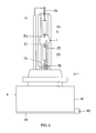
- the high-pressure discharge lamp according to the preferred exemplary embodiment of the invention shown schematically in FIG. 5 is a metal halide high-pressure discharge lamp for a motor vehicle headlight.
- This high-pressure discharge lamp La has a discharge vessel 1 made of quartz glass, in which an ionizable filling is enclosed gas-tight.
- the ionizable filling contains xenon and metal halide compounds, preferably iodides of the metals sodium, scandium, zinc and indium and ionizable filling preferably contains no mercury.
- the xenon cold filling pressure is approx. 10 bar.
- the two ends 1a, 1b of the discharge vessel 1 are each sealed by means of a molybdenum foil sealing 2a, 2b.
- Located in the interior of the discharge vessel 1 two electrodes E1, E2, between which forms during the lamp operation responsible for the light emission discharge arc.
- main electrodes E1, E2 are in each case electrically conductively connected via one of the molybdenum foil melts 2a, 2b to a current lead-out 3a, 3b led out of the discharge vessel 1.
- the discharge vessel 1 is enveloped by a glass outer bulb 5.
- the auxiliary starting electrode ZE is formed by a thin metallic coating on the inner surface of the outer bulb 5. Alternatively, this coating can also be mounted on the outside of the discharge vessel 1.
- the thin metallic coating ZE has the shape of an elongate strip which extends from the socket-near end of the outer bulb 5 approximately to the level of the discharge vessel center point.
- the lamp vessels 1, 5 are fixed in the plastic upper part 411 of a lamp cap 4.
- the cuboid part of the lamp base 4 is surrounded by a two-part metallic housing 41, 42, which serves for the electromagnetic shielding of the accommodated in the interior of the lamp cap 4 pulse ignition device.
- the electrical connection 40 of the high-pressure discharge lamp La serves to supply power to the high-pressure discharge lamp and the pulse ignition device arranged in the lamp base 4.
- the electrical connection 40 is connected via a shielded connection cable (not shown) to the control gear ECG (not shown) for the high-pressure discharge lamp.
- the shielding braid of the connection cable is connected to the internal circuit ground potential of the operating device and via a contact of the electrical connection 40 with the metal housing 41, 42, so that the metal housing 41, 42 is also at ground potential.
- the operating device ECG serves as an AC voltage source Q for the high-pressure discharge lamp and accommodated in the lamp base 4 pulse ignition device.
- the control gear ECG is connected via a shielded connection cable (not shown) to the electrical connection 40 of the high-pressure discharge lamp, so that the electrodes E1, E2 of the high-pressure discharge lamp La and the voltage input of the pulse ignition device (pulse source) are supplied with the alternating voltage generated by the operating device ECG.
- the voltage input of the pulse ignition device is connected in parallel to the discharge path of the high-pressure discharge lamp defined by the electrodes E1, E2.
- the secondary winding n2 of the pulse transformer T of the pulse ignition device is connected to the auxiliary starting electrode ZE of the high-pressure discharge lamp La.
- FIG. 2 shows details of the pulse ignition device (pulse source).
- the AC voltage provided by the AC voltage source Q is supplied to the voltage input of the pulse ignition device and rectified by the diode D to charge via the resistor R, the ignition capacitor C1, which is connected in a DC path parallel to the discharge path of the high pressure discharge lamp La.
- Parallel to the ignition capacitor C 1 the spark gap FS and the primary winding n1 of the ignition transformer T are connected.
- the ignition capacitor C1 discharges via the spark gap FS and the primary winding n1.
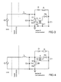
- FIG. 3 schematically shows the first embodiment of the high-pressure discharge lamp La according to the invention, including the components D, R, FS, C1, T of the pulse ignition device and a series resonant circuit L, C2 accommodated in the lamp base 4.
- the components L, C2 of the series resonant circuit are also accommodated in the lamp base 4.
- the resonance capacitance C2 is connected in parallel with the discharge path of the high-pressure discharge lamp La.
- a first terminal of the secondary winding n2 of the ignition transformer T is connected to the circuit-internal ground reference potential.
- the second terminal of the secondary winding n2 of the ignition transformer T is connected to the auxiliary ignition electrode ZE.
- the control gear ECG is a voltage transformer which uses the vehicle electrical system voltage to generate a nearly sinusoidal alternating voltage having an amplitude of approximately 100 V to 500 V and a frequency of approximately 2.6 MHz during the ignition phase of the high-pressure discharge lamp and a frequency generated by about 1 MHz after completion of the ignition phase.
- the second exemplary embodiment of the invention schematically illustrated in FIG. 4 differs from the exemplary embodiment shown in FIG. 3 only in that the first terminal of the secondary winding n2 of the ignition transformer T is connected to the electrode E1 at high electrical potential and not to the internal ground reference potential ,
- the embodiments illustrated in FIGS. 3 and 4 are identical. Therefore, identical components have been given the same reference numerals in these figures.
- the now conductive discharge path between the two electrodes E1, E2 forms a shunt to the resonant capacitance C2 and the voltage input of the pulse ignition, so that the voltage across the discharge path and thus also at the voltage input of the pulse ignition device significantly lower values.
- the breakdown voltage of the spark gap FS on the ignition capacitor C 1 is no longer achieved and the pulse ignition device does not generate any further ignition pulses for the high-pressure discharge lamp La. The shutdown of the pulse igniter thus takes place without further expenditure on components.
- a two-wire connection between the operating device electronic ballast and the connection 40 of the high-pressure discharge lamp La is sufficient since the pulse ignition device is supplied directly from the alternating voltage applied to the high-pressure discharge lamp.
- FIG. 6 shows a further exemplary embodiment of the invention, which differs from the first exemplary embodiment of the invention depicted in FIG. 1 only by the DC voltage separating capacitor C0 which is connected between the secondary winding n2 of the ignition transformer T and the auxiliary starting electrode ZE.
- the capacitance of the capacitor C0 can be freely selected within wide limits, without exerting a significant influence on the ignition process.
- the capacitor C0 is dimensioned so that the voltage drop across the capacitor C0 during the ignition process is smaller than the voltages that occur between the auxiliary starting electrode ZE and the two electrodes of the high-pressure discharge lamp La. Therefore, very small capacitance values are sufficient for the capacitor C0, for example 33 pF.
- the DC voltage separating capacitor C0 can also be integrated into the circuit arrangements according to FIGS. 2 to 4 analogously thereto. It prevents a direct current flow via the auxiliary ignition electrode ZE and contributes to the reduction of sodium loss due to the sodium diffusion in the discharge vessel of the high-pressure discharge lamp La.
- the ionizable filling in the discharge vessel of the high-pressure discharge lamp La also contains halides of the metals sodium, scandium, zinc and indium.
Landscapes
- Circuit Arrangements For Discharge Lamps (AREA)
- Arrangement Of Elements, Cooling, Sealing, Or The Like Of Lighting Devices (AREA)
- Discharge Lamps And Accessories Thereof (AREA)
Abstract
Description
- Die Erfindung betrifft eine Hochdruckentladungslampe gemäß dem Oberbegriff des Patentanspruchs 1 sowie ein Betriebsverfahren für eine Hochdruckentladungslampe.
- Eine derartige Hochdruckentladungslampe ist beispielsweise in der WO 98/18297 offenbart. Diese Offenlegungsschrift beschreibt eine Hochdruckentladungslampe mit einer Zündhilfselektrode und einer im Lampensockel angeordneten Impulszündvorrichtung zum Zünden der Gasentladung in dem Entladungsgefäß der Hochdruckentladungslampe. Die Impulszündvorrichtung und die Betriebsschaltung für die Hochdruckentladungslampe sind mittels eines Transformators galvanisch voneinander getrennt. Sowohl die Impulszündvorrichtung als auch die Betriebsschaltung sind zu ihrer Spannungsversorgung jeweils an eine Sekundärwicklung des Transformators angeschlossen, dessen Primärwicklungen als Bestandteil eines Push-Pull-Wechselrichters ausgebildet sind. Die Abschaltung der Impulszündvorrichtung nach erfolgreicher Zündung der Gasentladung erfolgt mittels eines Halbleiterschalters.
- Es ist Aufgabe der Erfindung, eine gattungsgemäße Hochdruckentladungslampe mit einer vereinfachten Spannungsversorgung für die Zündvorrichtung bereitzustellen und ein entsprechendes Betriebsverfahren anzugeben.
- Diese Aufgabe wird erfindungsgemäß durch die Merkmale des Patentanspruchs 1 gelöst. Besonders vorteilhafte Ausführungen der Erfindung sind in den abhängigen Patentansprüchen beschrieben.
- Die erfindungsgemäße Hochdruckentladungslampe besitzt innerhalb ihres Entladungsgefäßes angeordnete Elektroden, die eine Entladungsstrecke definieren, und eine innerhalb ihres Lampensockels angeordnete, als Impulszündvorrichtung ausgebildete Zündvorrichtung zum Zünden der Gasentladung in dem Entladungsgefäß sowie eine außerhalb des Entladungsgefäßes angeordnete Zündhilfselektrode, wobei der Spannungseingang der Impulszündvorrichtung erfindungsgemäß parallel zur Entladungsstrecke der Hochdruckentladungslampe geschaltet ist.
- Dadurch kann die Impulszündvorrichtung unmittelbar aus dem Spannungsabfall über der Entladungsstrecke der Hochdruckentladungslampe mit Energie versorgt werden. Eine separate Erzeugung der Versorgungsspannung für die Zündvorrichtung entfällt somit. Außerdem wird kein Schalter zum Deaktivieren der Impulszündvorrichtung nach erfolgreicher Zündung der Gasentladung in der Lampe benötigt, da der Spannungsabfall über der Entladungsstrecke nach erfolgter Zündung der Gasentladung deutlich zurückgeht und damit die an der Impulszündvorrichtung anliegende Spannung nicht mehr zur Erzeugung von Zündspannungsimpulsen ausreicht.
- Vorzugsweise ist bei der erfindungsgemäßen Hochdruckentladungslampe der Zündkondensator der Impulszündvorrichtung in einem parallel zur Entladungsstrecke der Hochdruckentladungslampe geschalteten Gleichstrompfad angeordnet. Dadurch wird der Ladestrom für den Zündkondensator unmittelbar aus dem Spannungsabfall über der Entladungsstrecke der Hochdruckentladungslampe generiert. Während der Zündphase der Hochdruckentladungslampe ist die Entladungsstrecke elektrisch isolierend und daher wird der Zündkondensator auf eine ausreichend hohe Spannung aufgeladen, um seine stoßweise Entladung über eine Funkenstrecke oder ein äquivalentes Schwellwertbauteil und die Erzeugung von Zündspannungsimpulsen mittels des Zündtransformators und der Zündhilfselektrode zu ermöglichen. Nach Beendigung der Zündphase ist die Entladungsstrecke der Hochdruckentladungslampe elektrisch leitend und der Spannungsabfall über der Entladungsstrecke entspricht nur noch der Brennspannung der Hochdruckentladungslampe, die zur Erzeugung weiterer Zündspannungsimpulse mittels der Impulszündvorrichtung nicht mehr ausreicht.
- Vorteilhafterweise ist in dem Lampensockel der erfindungsgemäßen Hochdruckentladungslampe zusätzlich ein Serienresonanzkreis untergebracht, wobei mindestens ein elektrisches Bauteil, das als Bestandteil des Serienresonanzkreises ausgebildet ist, beispielsweise die Resonanzkapazität oder die Resonanzinduktivität, parallel zur Entladungsstrecke geschaltet ist. Mittels des Serienresonanzkreises und des vorgenannten, parallel zur Entladungsstrecke geschalteten elektrischen Bauteils wird zumindest während der Zündphase der Hochdruckentladungslampe eine resonanzüberhöhte Wechselspannung generiert, die über der Entladungsstrecke abfällt und damit auch an dem Spannungseingang der Impulszündvorrichtung anliegt. Dadurch können die elektrischen Kontakte der Hochdruckentladungslampe sowie die elektrischen Zuleitungen zu der Hochdruckentladungslampe für geringere Spannungen konfektioniert werden, da alle Hochspannung führenden elektrischen Komponenten in dem Lampensockel untergebracht sind. Der Serienresonanzkreis gewährleistet ferner eine sichere Übernahme, das heißt, einen sicheren Übergang vom Zeitpunkt des ersten Durchbruchs der Entladungsstrecke zwischen den beiden Elektroden der Hochdruckentladungslampe bis sich eine Bogenentladung mit thermisch Elektronen emittierender Kathode einstellt. Die Übernahme wird auch als glow-to-arc-transition bezeichnet.
- Vorteilhafterweise ist gemäß einem bevorzugten Ausführungsbeispiel der Erfindung auch ein Gleichspannungstrennkondensator vorgesehen, um den Natriumverlust im Entladungsplasma bedingt durch die Diffusion von Natriumionen zur Entladungsgefäßwand zu reduzieren. Die Kapazität des Gleichspannungstrennkondensators wird dabei so dimensioniert, dass einerseits die Zündhilfselektrode mit einer ausreichend hohen Spannung zum Zünden der Gasentladung beaufschlagt wird und andererseits die vorgenannte Natriumdiffusion in hinreichendem Maß reduziert wird. Bei zu gro-βer Kapazität oder zu hohem Leckstrom des Gleichspannungstrennkondensators wird keine ausreichende Reduktion der Natriumdiffusion erreicht und bei zu kleiner Kapazität kann die Zündhilfselektrode nicht mit ausreichend hoher Spannung zum Zünden der Gasentladung beaufschlagt werden. Der Gleichspannungstrennkondensator ist vorzugsweise zwischen die Sekundärwicklung des Zündtransformators und die Zündhilfselektrode geschaltet.
- Nachstehend wird die Erfindung anhand eines bevorzugten Ausführungsbeispiels näher erläutert. Es zeigen:
- Figur 1
- Eine schematische Darstellung einer Schaltskizze der erfindungsgemäßen Hochdruckentladungslampe mit Impulszündvorrichtung
- Figur 2
- Die Schaltskizze aus Figur 1 mit Details der Impulszündvorrichtung
- Figur 3
- Eine schematische Darstellung einer Schaltskizze des ersten Ausführungsbeispiels der erfindungsgemäßen Hochdruckentladungslampe mit Impulszündvorrichtung
- Figur 4
- Eine schematische Darstellung einer Schaltskizze des zweiten Ausführungsbeispiels der erfindungsgemäßen Hochdruckentladungslampe mit Impulszündvorrichtung
- Figur 5
- Eine Seitenansicht der Hochdruckentladungslampe gemäß dem bevorzugten Ausführungsbeispiel der Erfindung in schematischer Darstellung
- Figur 6
- Eine schematische Darstellung einer Schaltskizze des dritten Ausführungsbeispiels der erfindungsgemäßen Hochdruckentladungslampe mit Impulszündvorrichtung
- Bei der in Figur 5 schematisch dargestellten Hochdruckentladungslampe gemäß des bevorzugten Ausführungsbeispiels der Erfindung handelt es sich um eine Halogen-Metalldampf-Hochdruckentladungslampe für einen Kraftfahrzeugscheinwerfer.
- Diese Hochdruckentladungslampe La besitzt ein Entladungsgefäß 1 aus Quarzglas, in dem eine ionisierbare Füllung gasdicht eingeschlossen ist. Die ionisierbare Füllung enthält Xenon und Metallhalogenidverbindungen, vorzugsweise Jodide der Metalle Natrium, Scandium, Zink und Indium und ionisierbare Füllung enthält vorzugsweise kein Quecksilber. Der Xenon-Kaltfülldruck beträgt ca. 10 bar. Die beiden Enden 1a, 1b des Entladungsgefäßes 1 sind jeweils mittels einer Molybdänfolien-Einschmelzung 2a, 2b abgedichtet. Im Innenraum des Entladungsgefäßes 1 befinden sich zwei Elektroden E1, E2, zwischen denen sich während des Lampenbetriebes der für die Lichtemission verantwortliche Entladungsbogen ausbildet. Diese Hauptelektroden E1, E2 sind jeweils über eine der Molybdänfolien-Einschmelzungen 2a, 2b elektrisch leitend mit einer aus dem Entladungsgefäß 1 herausgeführten Stromzuführung 3a, 3b verbunden. Das Entladungsgefäß 1 wird von einem gläsernen Außenkolben 5 umhüllt. Die Zündhilfselektrode ZE wird hier bei diesem Ausführungsbeispiel der Erfindung von einer dünnen metallischen Beschichtung auf der inneren Oberfläche des Außenkolbens 5 gebildet. Alternativ kann diese Beschichtung aber auch auf der Außenseite des Entladungsgefäßes 1 angebracht sein. Die dünne metallische Beschichtung ZE besitzt die Form eines lang gestreckten Streifens, der sich vom sockelnahen Ende des Außenkolbens 5 ungefähr bis auf die Höhe des Entladungsgefäßmittelpunktes erstreckt. Die Lampengefäße 1, 5 sind im aus Kunststoff bestehenden Oberteil 411 eines Lampensockels 4 fixiert. Der quaderförmige Teil des Lampensockels 4 ist von einem zweiteiligen metallischen Gehäuse 41, 42 umgeben, das zur elektromagnetischen Abschirmung der im Innenraum des Lampensockels 4 untergebrachten Impulszündvorrichtung dient. Der elektrische Anschluss 40 der Hochdruckentladungslampe La dient zur Spannungsversorgung der Hochdruckentladungslampe und der im Lampensockel 4 angeordneten Impulszündvorrichtung. Der elektrische Anschluss 40 ist über ein abgeschirmtes Verbindungskabel (nicht abgebildet) mit dem Betriebsgerät EVG (nicht abgebildet) für die Hochdruckentladungslampe verbunden. Das Abschirmgeflecht des Verbindungskabels ist mit dem schaltungsinternen Massepotential des Betriebsgerätes und über einen Kontakt des elektrischen Anschlusses 40 mit dem Metallgehäuse 41, 42 verbunden, so dass das Metallgehäuse 41, 42 ebenfalls auf Massepotential liegt.
- In der Figur 1 ist eine schematische Schaltskizze der erfindungsgemäßen Hochdruckentladungslampe, der im Lampensockel 4 angeordneten Impulszündvorrichtung (in Figur 1 als Impulsquelle bezeichnet) und des Betriebsgerätes EVG dargestellt. Das Betriebsgerät EVG dient als Wechselspannungsquelle Q für die Hochdruckentladungslampe und die im Lampensockel 4 untergebrachte Impulszündvorrichtung. Das Betriebsgerät EVG ist über ein abgeschirmtes Verbindungskabel (nicht abgebildet) mit dem elektrischen Anschluss 40 der Eiochdruckentladungslampe verbunden, so dass die Elektroden E1, E2 der Hochdruckentladungslampe La und der Spannungseingang der Impulszündvorrichtung (Impulsquelle) mit der von dem Betriebsgerät EVG erzeugten Wechselspannung beaufschlagt werden. Der Spannungseingang der Impulszündvorrichtung ist parallel zu der von den Elektroden E1, E2 definierten Entladungsstrecke der Hochdruckentladungslampe geschaltet. Die Sekundärwicklung n2 des Impulstransformators T der Impulszündvorrichtung ist mit der Zündhilfselektrode ZE der Hochdruckentladungslampe La verbunden.
- In der Figur 2 sind Details der Impulszündvorrichtung (Impulsquelle) dargestellt. Die von der Wechselspannungsquelle Q bereitgestellte Wechselspannung wird dem Spannungseingang der Impulszündvorrichtung zugeführt und mittels der Diode D gleichgerichtet, um über den Widerstand R den Zündkondensator C1, der in einem Gleichstrompfad parallel zur Entladungsstrecke der Hochdruckentladungslampe La geschaltet ist, aufzuladen. Parallel zu dem Zündkondensator C 1 sind die Funkenstrecke FS und die Primärwicklung n1 des Zündtransformators T geschaltet. Erreicht die Spannung an dem Zündkondensator C1 die Durchbruchsspannung der Funkenstrecke FS, so entlädt sich der Zündkondensator C1 über die Funkenstrecke FS und die Primärwicklung nl. In der Sekundärwicklung n2 des Zündtransformators T, die mit der Zündhilfselektrode ZE verbunden ist, werden dadurch Hochspannungsimpulse induziert, die der Zündhilfselektrode ZE zugeführt werden und zum Zünden der Gasentladung in dem Entladungsgefäß 1 der Hochdruckentladungslampe führen.
- In der Figur 3 ist die erste Ausführungsform der erfindungsgemäßen Hochdruckentladungslampe La inklusive der im Lampensockel 4 untergebrachten Bauteile D, R, FS, C1, T der Impulszündvorrichtung und eines Serienresonanzkreises L, C2 schematisch dargestellt. Die Bauteile L, C2 des Serienresonanzkreises sind ebenfalls im Lampensockel 4 untergebracht. Die Resonanzkapazität C2 ist parallel zur Entladungsstrecke der Hochdruckentladungslampe La geschaltet. Ein erster Anschluss der Sekundärwicklung n2 des Zündtransformators T ist mit dem schaltungsinternen Massebezugspotential verbunden. Der zweite Anschluss der Sekundärwicklung n2 des Zündtransformators T ist mit der Zündhilfselektrode ZE verbunden. Während der Zündphase der Hochdruckentladungslampe La wird der Serienresonanzkreis L. C2 in Resonanz betrieben, so dass an der Resonanzkapazität C2 und damit auch über der Entladungsstrecke der Hochdruckentladungslampe La sowie an dem Spannungseingang der Impulszündvorrichtung eine resonanzüberhöhte Wechselspannung bereitgestellt wird, die eine um den Faktor 2 bis 10 höhere Amplitude als die von der Wechselspannungsquelle Q generierte Wechselspannung besitzt. Mit Hilfe der Bauteile D, R, FS, Cl, T der Impulszündvorrichtung werden daraus Hochspannungsimpulse für die Zündhilfselektrode mit Spannungen im Bereich von ca. 5 kV bis 30 kV erzeugt. Eine geeignete Dimensionierung der elektrischen Bauteile der Impulszündvorrichtung und des Serienresonanzkreises zum Erzeugen einer Zündspannung von ca. 30 kV bzw. einer Zündspannung von ca. 5 kV ist in der Tabelle 1 bzw. 2 offenbart.
- Bei dem Betriebsgerät EVG handelt es sich um einen Spannungswandler, der aus der Bordnetzspannung des Kraftfahrzeugs eine nahezu sinusförmige Wechselspannung mit einer Amplitude von ca. 100 V bis 500 V und einer Frequenz von ca. 2,6 MHz während der Zündphase der Hochdruckentladungslampe sowie einer Frequenz von ca. 1 MHz nach Beendigung der Zündphase generiert.
- Das in der Figur 4 schematisch dargestellte zweite Ausführungsbeispiel der Erfindung unterscheidet sich von dem in Figur 3 abgebildeten Ausführungsbeispiel nur dadurch, dass der erste Anschluss der Sekundärwicklung n2 des Zündtransformators T mit der auf hohem elektrischen Potential befindlichen Elektrode E1 und nicht mit dem schaltungsinternen Massebezugspotential verbunden ist. In allen anderen Details stimmen die in den Figuren 3 und 4 dargestellten Ausführungsbeispiele überein. Daher wurden in diesen Figuren identische Bauteile mit denselben Bezugszeichen versehen.
- Nach erfolgter Zündung der Gasentladung in dem Entladungsgefäß 1 der Hochdruckentladungslampe La bildet die nun leitfähige Entladungsstrecke zwischen den beiden Elektroden E1 , E2 einen Nebenschluss zu der Resonanzkapazität C2 und dem Spannungseingang der Impulszündvorrichtung, so dass die Spannung über der Entladungsstrecke und damit auch am Spannungseingang der Impulszündvorrichtung deutlich geringere Werte annimmt. Dadurch wird die Durchbruchsspannung der Funkenstrecke FS an dem Zündkondensator C 1 nicht mehr erreicht und die Impulszündvorrichtung generiert keine weitere Zündimpulse für die Hochdruckentladungslampe La. Die Abschaltung der Impulszündvorrichtung erfolgt somit ohne weiteren Bauelementeaufwand.
- Zur Spannungsversorgung der Hochdruckentladungslampe La und der im Lampensockel 4 untergebrachten Impulszündvorrichtung genügt eine Zwei-Leiterverbindung zwischen dem Betriebsgerät EVG und dem Anschluss 40 der Hochdruckentladungslampe La, da die Impulszündvorrichtung direkt aus der an der Hochdruckentladungslampe anliegenden Wechselspannung versorgt wird.
- In Figur 6 ist ein weiteres Ausführungsbeispiel der Erfindung dargestellt, das sich von dem in Figur 1 abgebildeten ersten Ausführungsbeispiel der Erfindung nur durch den Gleichspannungstrennkondensator C0 unterscheidet, der zwischen die Sekundärwicklung n2 des Zündtransformators T und die Zündhilfselektrode ZE geschaltet ist. Die Kapazität des Kondensators C0 kann in weiten Grenzen frei gewählt werden, ohne einen nennenswerten Einfluss auf den Zündvorgang auszuüben. Vorzugsweise wird der Kondensator C0 so dimensioniert, dass der Spannungsabfall am Kondensator C0 während des Zündvorgangs kleiner als die sich zwischen der Zündhilfselektrode ZE und den beiden Elektroden der Hochdruckentladungslampe La einstellenden Spannungen ist. Es genügen daher sehr kleine Kapazitätswerte für den Kondensator C0, beispielsweise 33 pF. Aber auch deutlich größere Werte für die Kapazität des Kondensators C0 wie etwa 10 nF sind möglich. Der Gleichspannungstrennkondensator C0 kann analog dazu auch in die Schaltungsanordnungen gemäß der Figuren 2 bis 4 integriert werden. Er verhindert einen Gleichstromfluss über die Zündhilfselektrode ZE und trägt zur Reduktion des durch die Natriumdiffusion bedingten Natriumverlustes im Entladungsgefäß der Hochdruckentladungslampe La bei. Die ionisierbare Füllung im Entladungsgefäß der Hochdruckentladungslampe La enthält nämlich neben Xenon auch Halogenide der Metalle Natrium, Scandium, Zink und Indium.
Tabelle 1: Dimensionierung der in den Figuren 3 und 4 abgebildeten elektrischen Bauteile zum Erzeugen einer Zündspannung von ca. 30 kV C1 10 nF C2 120 pF D BY505 FS 2000 V L 30 µH R 33 kOhm T n1 = 10 Windungen, n2 = 190 Windungen Tabelle 2: Alternative Dimensionierung der in den Figuren 3 und 4 abgebildeten elektrischen Bauteile zum Erzeugen einer Zündspannung von ca. 5 kV C1 33 nF C2 120 pF D zwei USIM in Reihe FS 800 V L 30 µH R 10 kOhm T n1 = 10 Windungen, n2 = 75 Windungen
Claims (8)
- Hochdruckentladungslampe mit innerhalb ihres Entladungsgefäßes (1) angeordneten Elektroden (E1, E2), die eine Entladungsstrecke für eine Gasentladung in dem Entladungsgefäß (1) definieren, und mit einer innerhalb des Lampensockels (4) der Hochdruckentladungslampe (La) angeordneten, als Impulszündvorrichtung ausgebildeten Zündvorrichtung zum Zünden der Gasentladung in dem Entladungsgefäß (1) sowie mit einer außerhalb ihres Entladungsgefäßes (1) angeordneten, an die Impulszündvorrichtung gekoppelten Zündhilfselektrode (ZE), dadurch gekennzeichnet, dass der Spannungseingang der Impulszündvorrichtung parallel zu der Entladungsstrecke der Hochdruckentladungslampe (La) geschaltet ist.
- Hochdruckentladungslampe nach Anspruch 1, dadurch gekennzeichnet, dass der Zündkondensator (C1) der Impulszündvorrichtung in einem parallel zur Entladungsstrecke der Hochdruckentladungslampe (La) geschalteten Gleichstrompfad angeordnet ist.
- Hochdruckentladungslampe nach Anspruch 1, dadurch gekennzeichnet, dass parallel zur Entladungsstrecke mindestens ein elektrisches Bauteil (C2 oder L) geschaltet ist, das als Bestandteil eines Serienresonanzkreises (L, C2) ausgebildet ist.
- Hochdruckentladungslampe nach Anspruch 1, dadurch gekennzeichnet, dass ein Gleichspannungstrennkondensator (C0) vorgesehen ist.
- Verfahren zum Betreiben einer Hochdruckentladungslampe, wobei die zum Zünden der Gasentladung in dem Entladungsgefäß (1) der Hochdruckentladungslampe (La) erforderliche Zündspannung mit Hilfe einer Impulszündvorrichtung generiert wird, die eine außerhalb des Entladungsgefäßes (1) angeordnete Zündhilfselektrode (ZE) der Hochdruckentladungslampe (La) während der Zündphase mit Spannungsimpulsen beaufschlagt, dadurch gekennzeichnet, dass die Spannung über der Entladungsstrecke der Hochdruckentladungslampe (La) der Impulszündvorrichtung als Versorgungsspannung zugeführt wird.
- Verfahren nach Anspruch 5, dadurch gekennzeichnet, dass der Strom zum Aufladen des Zündkondensators (C1) der Impulszündvorrichtung aus der Spannung über der Entladungsstrecke der Hochdruckentladungslampe (La) erzeugt wird.
- Verfahren nach Anspruch 5, dadurch gekennzeichnet, dass die Entladungsstrecke der Hochdruckentladungslampe (La) nach dem Zünden der Gasentladung in dem Entladungsgefäß (1) einen Nebenschluss zu dem Zündkondensator (C1) bildet.
- Verfahren nach Anspruch 5, dadurch gekennzeichnet, dass über der Entladungsstrecke der Hochdruckentladungslampe (La) zumindest während der Zündphase der Hochdruckentladungslampe (La) eine resonanzüberhöhte Wechselspannung bereitgestellt wird.
Applications Claiming Priority (1)
| Application Number | Priority Date | Filing Date | Title |
|---|---|---|---|
| DE102004056002A DE102004056002A1 (de) | 2004-11-19 | 2004-11-19 | Hochdruckentladungslampe mit Impulszündvorrichtung und Betriebsverfahren für eine Hochdruckentladungslampe |
Publications (2)
| Publication Number | Publication Date |
|---|---|
| EP1659835A1 true EP1659835A1 (de) | 2006-05-24 |
| EP1659835B1 EP1659835B1 (de) | 2008-01-30 |
Family
ID=35583310
Family Applications (1)
| Application Number | Title | Priority Date | Filing Date |
|---|---|---|---|
| EP05024594A Expired - Lifetime EP1659835B1 (de) | 2004-11-19 | 2005-11-10 | Hochdruckentladungslampe mit Impulszündvorrichtung und Betriebsverfahren für eine Hochdruckentladungslampe |
Country Status (8)
| Country | Link |
|---|---|
| US (1) | US7271547B2 (de) |
| EP (1) | EP1659835B1 (de) |
| JP (1) | JP2006147577A (de) |
| CN (1) | CN1802061B (de) |
| AT (1) | ATE385396T1 (de) |
| CA (1) | CA2526996A1 (de) |
| DE (2) | DE102004056002A1 (de) |
| ES (1) | ES2298910T3 (de) |
Cited By (1)
| Publication number | Priority date | Publication date | Assignee | Title |
|---|---|---|---|---|
| WO2007093525A1 (de) * | 2006-02-15 | 2007-08-23 | Osram Gesellschaft mit beschränkter Haftung | Hochdruckentladungslampe |
Families Citing this family (6)
| Publication number | Priority date | Publication date | Assignee | Title |
|---|---|---|---|---|
| CN1960593B (zh) * | 2006-11-08 | 2010-08-25 | 杭州电子科技大学 | 一种高压气体放电灯电子镇流器的智能触发方法 |
| DE102006058538A1 (de) * | 2006-12-12 | 2008-06-19 | Patent-Treuhand-Gesellschaft für elektrische Glühlampen mbH | Zündvorrichtung für eine Hochdruckentladungslampe und Hochdruckentladungslampe mit Zündvorrichtung |
| WO2010121964A1 (en) | 2009-04-24 | 2010-10-28 | Osram Gesellschaft mit beschränkter Haftung | Lamp-coupler-unit for electrodeless high intensity discharge (ehid) lamps with a data memory and communication and an impedance-controlled feedthrough and electrodeless high intensity discharge system with such lamp-coupler-unit |
| EP2524580A2 (de) * | 2010-09-22 | 2012-11-21 | Osram AG | Verfahren zum zünden einer hochdruckentladungslampe |
| DE102014100298A1 (de) * | 2013-09-13 | 2015-03-19 | Von Ardenne Gmbh | Blitzlampe und Verfahren zum Unterdrücken einer Selbstzündung |
| DK2983194T3 (en) * | 2014-08-04 | 2018-05-22 | Flowil Int Lighting Holding B V | REMOVABLE ENERGY SAVE LIGHT WITH INTEGRATED MAGNETIC COIL AND CERAMIC METAL HALOGEN LIGHT PIPE FOR REPLACEMENT OF MERCURY Vapor Lamps, HIGH PRESSURE SODIUM LAMPS AND QUARTER METAL HALOGS |
Citations (5)
| Publication number | Priority date | Publication date | Assignee | Title |
|---|---|---|---|---|
| DE2717853A1 (de) * | 1976-05-05 | 1977-11-17 | Philips Nv | Metalldampfentladungslampe |
| DE3148821A1 (de) * | 1980-12-16 | 1982-07-15 | Naamloze Vennootschap Philips' Gloeilampenfabrieken, 5621 Eindhoven | "starter zum zuenden einer gas- und/oder dampfentladungslampe sowie elektrische anordnung und lampe mit einem derartigen starter" |
| US4743810A (en) * | 1984-11-06 | 1988-05-10 | U.S. Philips Corporation | Circuit arrangement for operating a high-pressure discharge lamp |
| DE19610385A1 (de) * | 1996-03-16 | 1997-09-18 | Bosch Gmbh Robert | Gasentladungslampe, insbesondere für Kraftfahrzeug-Scheinwerfer |
| US6034477A (en) * | 1997-12-16 | 2000-03-07 | U.S. Philips Corporation | High-pressure discharge lamp |
Family Cites Families (11)
| Publication number | Priority date | Publication date | Assignee | Title |
|---|---|---|---|---|
| EP0181666B1 (de) * | 1984-11-06 | 1990-01-03 | Koninklijke Philips Electronics N.V. | Hochdruckentladungslampe |
| JPH0513185A (ja) * | 1990-09-07 | 1993-01-22 | Matsushita Electric Ind Co Ltd | 放電灯点灯装置 |
| DE4121009C2 (de) * | 1991-06-21 | 1994-01-13 | Prolux Maschinenbau Gmbh | Schaltungsanordnung zum Betrieb einer Entladungslampe |
| DE19644115A1 (de) | 1996-10-23 | 1998-04-30 | Patent Treuhand Ges Fuer Elektrische Gluehlampen Mbh | Schaltungsanordnung zum Betrieb einer Hochdruckentladungslampe sowie Beleuchtungssystem mit einer Hochdruckentladungslampe und einem Betriebsgerät für die Hochdruckentladungslampe |
| JPH11238488A (ja) * | 1997-06-06 | 1999-08-31 | Toshiba Lighting & Technology Corp | メタルハライド放電ランプ、メタルハライド放電ランプ点灯装置および照明装置 |
| JP3291275B2 (ja) * | 1999-09-30 | 2002-06-10 | 松下電工株式会社 | 放電灯点灯装置 |
| JP2003092198A (ja) * | 2001-09-18 | 2003-03-28 | Ushio Inc | 光源装置 |
| DE10210717A1 (de) * | 2002-03-12 | 2003-10-02 | Patent Treuhand Ges Fuer Elektrische Gluehlampen Mbh | Schaltungsanordnung zur Zündung von Hochdruck-Entladungslampen |
| JP4037142B2 (ja) * | 2002-03-27 | 2008-01-23 | 東芝ライテック株式会社 | メタルハライドランプおよび自動車用前照灯装置 |
| US6798139B2 (en) * | 2002-06-25 | 2004-09-28 | General Electric Company | Three electrode ceramic metal halide lamp |
| JP4317908B2 (ja) * | 2003-11-07 | 2009-08-19 | ハリソン東芝ライティング株式会社 | 自動車前照灯・赤外暗視装置兼用メタルハライドランプおよびメタルハライドランプ点灯装置 |
-
2004
- 2004-11-19 DE DE102004056002A patent/DE102004056002A1/de not_active Withdrawn
-
2005
- 2005-11-10 EP EP05024594A patent/EP1659835B1/de not_active Expired - Lifetime
- 2005-11-10 AT AT05024594T patent/ATE385396T1/de not_active IP Right Cessation
- 2005-11-10 ES ES05024594T patent/ES2298910T3/es not_active Expired - Lifetime
- 2005-11-10 DE DE502005002717T patent/DE502005002717D1/de not_active Expired - Lifetime
- 2005-11-14 US US11/272,085 patent/US7271547B2/en not_active Expired - Fee Related
- 2005-11-15 CA CA002526996A patent/CA2526996A1/en not_active Abandoned
- 2005-11-18 JP JP2005334699A patent/JP2006147577A/ja active Pending
- 2005-11-18 CN CN2005101380511A patent/CN1802061B/zh not_active Expired - Fee Related
Patent Citations (5)
| Publication number | Priority date | Publication date | Assignee | Title |
|---|---|---|---|---|
| DE2717853A1 (de) * | 1976-05-05 | 1977-11-17 | Philips Nv | Metalldampfentladungslampe |
| DE3148821A1 (de) * | 1980-12-16 | 1982-07-15 | Naamloze Vennootschap Philips' Gloeilampenfabrieken, 5621 Eindhoven | "starter zum zuenden einer gas- und/oder dampfentladungslampe sowie elektrische anordnung und lampe mit einem derartigen starter" |
| US4743810A (en) * | 1984-11-06 | 1988-05-10 | U.S. Philips Corporation | Circuit arrangement for operating a high-pressure discharge lamp |
| DE19610385A1 (de) * | 1996-03-16 | 1997-09-18 | Bosch Gmbh Robert | Gasentladungslampe, insbesondere für Kraftfahrzeug-Scheinwerfer |
| US6034477A (en) * | 1997-12-16 | 2000-03-07 | U.S. Philips Corporation | High-pressure discharge lamp |
Cited By (2)
| Publication number | Priority date | Publication date | Assignee | Title |
|---|---|---|---|---|
| WO2007093525A1 (de) * | 2006-02-15 | 2007-08-23 | Osram Gesellschaft mit beschränkter Haftung | Hochdruckentladungslampe |
| US8013508B2 (en) | 2006-02-15 | 2011-09-06 | Osram Ag | High-pressure discharge lamp |
Also Published As
| Publication number | Publication date |
|---|---|
| EP1659835B1 (de) | 2008-01-30 |
| CA2526996A1 (en) | 2006-05-19 |
| ATE385396T1 (de) | 2008-02-15 |
| CN1802061B (zh) | 2011-08-24 |
| US7271547B2 (en) | 2007-09-18 |
| JP2006147577A (ja) | 2006-06-08 |
| DE102004056002A1 (de) | 2006-05-24 |
| US20060108942A1 (en) | 2006-05-25 |
| ES2298910T3 (es) | 2008-05-16 |
| CN1802061A (zh) | 2006-07-12 |
| DE502005002717D1 (de) | 2008-03-20 |
Similar Documents
| Publication | Publication Date | Title |
|---|---|---|
| EP0868833B1 (de) | Hochdruckentladungslampe mit einer zündhilfselektrode sowie schaltungsanordnung und verfahren zum betrieb | |
| EP1654913B1 (de) | Vorschaltgerät für mindestens eine hochdruckentladungslampe, betriebsverfahren und beleuchtungssystem für eine hochdruckentladungslampe | |
| EP1985160B1 (de) | Schaltungsanordnung und verfahren zum ansteuern einer hochdruck-gasentladungslampe | |
| EP1659835B1 (de) | Hochdruckentladungslampe mit Impulszündvorrichtung und Betriebsverfahren für eine Hochdruckentladungslampe | |
| EP2100484A1 (de) | Zündvorrichtung für eine hochdruckentladungslampe und hochdruckentladungslampe mit zündvorrichtung | |
| EP1741320B1 (de) | Schaltungsanordnung zum betrieb von hochdruckentladungslampen und betriebsverfahren für eine hochdruckentladungslampe | |
| EP1124406B1 (de) | Betriebsverfahren für eine Entladungslampe mit mindestens einer dielektrisch behinderten Elektrode | |
| EP1033906B1 (de) | Einseitig gesockelte Hochdruckentladungslampe mit im Sockel integrierter Zündvorrichtung | |
| EP1667200B1 (de) | Hochdruckentladungslampe und Beleuchtungsvorrichtung mit Hochdruckentladungslampe | |
| EP1653785B1 (de) | Zündvorrichtung für eine Hochdruckentladungslampe und Hochdruckentladungslampe mit Zündvorrichtung sowie Betriebsverfahren für eine Hochdruckentladungslampe | |
| DE102009054376B4 (de) | Hochdruckentladungslampe | |
| WO2006108407A1 (de) | Zündhilfselektrodezündvorrichtung mit funkenstrecke | |
| EP1894448B1 (de) | Vorrichtung und verfahren zum betreiben einer hochdruckentladungslampe | |
| WO2008046797A1 (de) | Zündvorrichtung für eine hochdruckentladungslampe und hochdruckentladungslampe sowie verfahren zum zünden einer gasentladung in einer hochdruckentladungslampe | |
| DE19608658C1 (de) | Schaltungsanordnung zum Zünden und Betreiben einer Hochdruckgasentladungslampe | |
| DE102005023798A1 (de) | Vorrichtung zum Betreiben oder Zünden einer Hochdruckentladungslampe, Lampensockel und Beleuchtungssystem mit einer derartigen Vorrichtung sowie Verfahren zum Betreiben einer Hochdruckentladungslampe | |
| US8022644B2 (en) | Gas discharge lamp ignition | |
| WO2004054327A1 (de) | Elektrische schaltung zum zünden einer entladungslampe und verfahren zum zünden der entladungslampe | |
| EP0595333A1 (de) | Zündschaltung für eine Hochdruckmetalldampfentladungslampe | |
| DE102008009144A1 (de) | Verfahren zum Zünden der Gasentladung in einer Hochdruckentladungslampe | |
| DE102005035745A1 (de) | Zündschaltung zum Zünden einer Entladungslampe und Verfahren zum Zünden der Entladungslampe | |
| WO2013135518A1 (de) | Zündvorrichtung mit halbleiter - schalter, für eine hochdruckentladungslampe, und betriebsvorrichtung mit einer derartigen zündvorrichtung | |
| DE102006028821A1 (de) | Vorrichtung und Verfahren zum Betreiben einer Hochdruckentladungslampe | |
| DE102005020773A1 (de) | Vorrichtung zum Betreiben oder Zünden einer Hochdruckentladungslampe, Lampensockel und Beleuchtungssystem mit einer derartigen Vorrichtung sowie Verfahren zum Betreiben einer Hochdruckentladungslampe | |
| DE102005060797A1 (de) | Vorrichtung zur Verbesserung der elektromagnetischen Verträglichkeit einer Hochdruckentladungslampe |
Legal Events
| Date | Code | Title | Description |
|---|---|---|---|
| PUAI | Public reference made under article 153(3) epc to a published international application that has entered the european phase |
Free format text: ORIGINAL CODE: 0009012 |
|
| AK | Designated contracting states |
Kind code of ref document: A1 Designated state(s): AT BE BG CH CY CZ DE DK EE ES FI FR GB GR HU IE IS IT LI LT LU LV MC NL PL PT RO SE SI SK TR |
|
| AX | Request for extension of the european patent |
Extension state: AL BA HR MK YU |
|
| 17P | Request for examination filed |
Effective date: 20060619 |
|
| 17Q | First examination report despatched |
Effective date: 20060801 |
|
| AKX | Designation fees paid |
Designated state(s): AT BE BG CH CY CZ DE DK EE ES FI FR GB GR HU IE IS IT LI LT LU LV MC NL PL PT RO SE SI SK TR |
|
| GRAP | Despatch of communication of intention to grant a patent |
Free format text: ORIGINAL CODE: EPIDOSNIGR1 |
|
| GRAS | Grant fee paid |
Free format text: ORIGINAL CODE: EPIDOSNIGR3 |
|
| GRAA | (expected) grant |
Free format text: ORIGINAL CODE: 0009210 |
|
| AK | Designated contracting states |
Kind code of ref document: B1 Designated state(s): AT BE BG CH CY CZ DE DK EE ES FI FR GB GR HU IE IS IT LI LT LU LV MC NL PL PT RO SE SI SK TR |
|
| REG | Reference to a national code |
Ref country code: GB Ref legal event code: FG4D Free format text: NOT ENGLISH |
|
| REG | Reference to a national code |
Ref country code: CH Ref legal event code: EP |
|
| REG | Reference to a national code |
Ref country code: IE Ref legal event code: FG4D Free format text: LANGUAGE OF EP DOCUMENT: GERMAN |
|
| REF | Corresponds to: |
Ref document number: 502005002717 Country of ref document: DE Date of ref document: 20080320 Kind code of ref document: P |
|
| REG | Reference to a national code |
Ref country code: ES Ref legal event code: FG2A Ref document number: 2298910 Country of ref document: ES Kind code of ref document: T3 |
|
| REG | Reference to a national code |
Ref country code: SE Ref legal event code: TRGR |
|
| GBT | Gb: translation of ep patent filed (gb section 77(6)(a)/1977) |
Effective date: 20080430 |
|
| PG25 | Lapsed in a contracting state [announced via postgrant information from national office to epo] |
Ref country code: IS Free format text: LAPSE BECAUSE OF FAILURE TO SUBMIT A TRANSLATION OF THE DESCRIPTION OR TO PAY THE FEE WITHIN THE PRESCRIBED TIME-LIMIT Effective date: 20080530 Ref country code: FI Free format text: LAPSE BECAUSE OF FAILURE TO SUBMIT A TRANSLATION OF THE DESCRIPTION OR TO PAY THE FEE WITHIN THE PRESCRIBED TIME-LIMIT Effective date: 20080130 |
|
| ET | Fr: translation filed | ||
| REG | Reference to a national code |
Ref country code: HU Ref legal event code: AG4A Ref document number: E003314 Country of ref document: HU |
|
| PG25 | Lapsed in a contracting state [announced via postgrant information from national office to epo] |
Ref country code: PL Free format text: LAPSE BECAUSE OF FAILURE TO SUBMIT A TRANSLATION OF THE DESCRIPTION OR TO PAY THE FEE WITHIN THE PRESCRIBED TIME-LIMIT Effective date: 20080130 Ref country code: SI Free format text: LAPSE BECAUSE OF FAILURE TO SUBMIT A TRANSLATION OF THE DESCRIPTION OR TO PAY THE FEE WITHIN THE PRESCRIBED TIME-LIMIT Effective date: 20080130 Ref country code: PT Free format text: LAPSE BECAUSE OF FAILURE TO SUBMIT A TRANSLATION OF THE DESCRIPTION OR TO PAY THE FEE WITHIN THE PRESCRIBED TIME-LIMIT Effective date: 20080630 Ref country code: LV Free format text: LAPSE BECAUSE OF FAILURE TO SUBMIT A TRANSLATION OF THE DESCRIPTION OR TO PAY THE FEE WITHIN THE PRESCRIBED TIME-LIMIT Effective date: 20080130 |
|
| REG | Reference to a national code |
Ref country code: IE Ref legal event code: FD4D |
|
| PG25 | Lapsed in a contracting state [announced via postgrant information from national office to epo] |
Ref country code: SK Free format text: LAPSE BECAUSE OF FAILURE TO SUBMIT A TRANSLATION OF THE DESCRIPTION OR TO PAY THE FEE WITHIN THE PRESCRIBED TIME-LIMIT Effective date: 20080130 Ref country code: CZ Free format text: LAPSE BECAUSE OF FAILURE TO SUBMIT A TRANSLATION OF THE DESCRIPTION OR TO PAY THE FEE WITHIN THE PRESCRIBED TIME-LIMIT Effective date: 20080130 Ref country code: IE Free format text: LAPSE BECAUSE OF FAILURE TO SUBMIT A TRANSLATION OF THE DESCRIPTION OR TO PAY THE FEE WITHIN THE PRESCRIBED TIME-LIMIT Effective date: 20080130 Ref country code: DK Free format text: LAPSE BECAUSE OF FAILURE TO SUBMIT A TRANSLATION OF THE DESCRIPTION OR TO PAY THE FEE WITHIN THE PRESCRIBED TIME-LIMIT Effective date: 20080130 |
|
| PG25 | Lapsed in a contracting state [announced via postgrant information from national office to epo] |
Ref country code: RO Free format text: LAPSE BECAUSE OF FAILURE TO SUBMIT A TRANSLATION OF THE DESCRIPTION OR TO PAY THE FEE WITHIN THE PRESCRIBED TIME-LIMIT Effective date: 20080130 |
|
| PLBE | No opposition filed within time limit |
Free format text: ORIGINAL CODE: 0009261 |
|
| STAA | Information on the status of an ep patent application or granted ep patent |
Free format text: STATUS: NO OPPOSITION FILED WITHIN TIME LIMIT |
|
| 26N | No opposition filed |
Effective date: 20081031 |
|
| PG25 | Lapsed in a contracting state [announced via postgrant information from national office to epo] |
Ref country code: LT Free format text: LAPSE BECAUSE OF FAILURE TO SUBMIT A TRANSLATION OF THE DESCRIPTION OR TO PAY THE FEE WITHIN THE PRESCRIBED TIME-LIMIT Effective date: 20080130 |
|
| PGFP | Annual fee paid to national office [announced via postgrant information from national office to epo] |
Ref country code: NL Payment date: 20081111 Year of fee payment: 4 |
|
| PGFP | Annual fee paid to national office [announced via postgrant information from national office to epo] |
Ref country code: ES Payment date: 20081216 Year of fee payment: 4 |
|
| PGFP | Annual fee paid to national office [announced via postgrant information from national office to epo] |
Ref country code: SE Payment date: 20081106 Year of fee payment: 4 Ref country code: BE Payment date: 20081119 Year of fee payment: 4 |
|
| PG25 | Lapsed in a contracting state [announced via postgrant information from national office to epo] |
Ref country code: EE Free format text: LAPSE BECAUSE OF FAILURE TO SUBMIT A TRANSLATION OF THE DESCRIPTION OR TO PAY THE FEE WITHIN THE PRESCRIBED TIME-LIMIT Effective date: 20080130 Ref country code: BG Free format text: LAPSE BECAUSE OF FAILURE TO SUBMIT A TRANSLATION OF THE DESCRIPTION OR TO PAY THE FEE WITHIN THE PRESCRIBED TIME-LIMIT Effective date: 20080430 |
|
| PG25 | Lapsed in a contracting state [announced via postgrant information from national office to epo] |
Ref country code: MC Free format text: LAPSE BECAUSE OF NON-PAYMENT OF DUE FEES Effective date: 20081130 |
|
| PG25 | Lapsed in a contracting state [announced via postgrant information from national office to epo] |
Ref country code: CY Free format text: LAPSE BECAUSE OF FAILURE TO SUBMIT A TRANSLATION OF THE DESCRIPTION OR TO PAY THE FEE WITHIN THE PRESCRIBED TIME-LIMIT Effective date: 20080130 |
|
| PG25 | Lapsed in a contracting state [announced via postgrant information from national office to epo] |
Ref country code: AT Free format text: LAPSE BECAUSE OF NON-PAYMENT OF DUE FEES Effective date: 20081110 |
|
| BERE | Be: lapsed |
Owner name: PATENT-TREUHAND-GESELLSCHAFT FUR ELEKTRISCHE GLUH Effective date: 20091130 |
|
| REG | Reference to a national code |
Ref country code: NL Ref legal event code: V1 Effective date: 20100601 |
|
| EUG | Se: european patent has lapsed | ||
| REG | Reference to a national code |
Ref country code: CH Ref legal event code: PL |
|
| PG25 | Lapsed in a contracting state [announced via postgrant information from national office to epo] |
Ref country code: LU Free format text: LAPSE BECAUSE OF NON-PAYMENT OF DUE FEES Effective date: 20081110 |
|
| PG25 | Lapsed in a contracting state [announced via postgrant information from national office to epo] |
Ref country code: TR Free format text: LAPSE BECAUSE OF FAILURE TO SUBMIT A TRANSLATION OF THE DESCRIPTION OR TO PAY THE FEE WITHIN THE PRESCRIBED TIME-LIMIT Effective date: 20080130 |
|
| PG25 | Lapsed in a contracting state [announced via postgrant information from national office to epo] |
Ref country code: CH Free format text: LAPSE BECAUSE OF NON-PAYMENT OF DUE FEES Effective date: 20091130 Ref country code: BE Free format text: LAPSE BECAUSE OF NON-PAYMENT OF DUE FEES Effective date: 20091130 Ref country code: LI Free format text: LAPSE BECAUSE OF NON-PAYMENT OF DUE FEES Effective date: 20091130 Ref country code: GR Free format text: LAPSE BECAUSE OF FAILURE TO SUBMIT A TRANSLATION OF THE DESCRIPTION OR TO PAY THE FEE WITHIN THE PRESCRIBED TIME-LIMIT Effective date: 20080501 Ref country code: NL Free format text: LAPSE BECAUSE OF NON-PAYMENT OF DUE FEES Effective date: 20100601 |
|
| REG | Reference to a national code |
Ref country code: ES Ref legal event code: FD2A Effective date: 20110309 |
|
| PGFP | Annual fee paid to national office [announced via postgrant information from national office to epo] |
Ref country code: GB Payment date: 20101111 Year of fee payment: 6 |
|
| PGFP | Annual fee paid to national office [announced via postgrant information from national office to epo] |
Ref country code: HU Payment date: 20110117 Year of fee payment: 6 |
|
| PG25 | Lapsed in a contracting state [announced via postgrant information from national office to epo] |
Ref country code: SE Free format text: LAPSE BECAUSE OF NON-PAYMENT OF DUE FEES Effective date: 20091111 |
|
| PGFP | Annual fee paid to national office [announced via postgrant information from national office to epo] |
Ref country code: DE Payment date: 20110121 Year of fee payment: 6 |
|
| PG25 | Lapsed in a contracting state [announced via postgrant information from national office to epo] |
Ref country code: ES Free format text: LAPSE BECAUSE OF NON-PAYMENT OF DUE FEES Effective date: 20110308 |
|
| PG25 | Lapsed in a contracting state [announced via postgrant information from national office to epo] |
Ref country code: ES Free format text: LAPSE BECAUSE OF NON-PAYMENT OF DUE FEES Effective date: 20091111 |
|
| PGFP | Annual fee paid to national office [announced via postgrant information from national office to epo] |
Ref country code: IT Payment date: 20081130 Year of fee payment: 4 |
|
| PGFP | Annual fee paid to national office [announced via postgrant information from national office to epo] |
Ref country code: FR Payment date: 20111201 Year of fee payment: 7 |
|
| REG | Reference to a national code |
Ref country code: DE Ref legal event code: R081 Ref document number: 502005002717 Country of ref document: DE Owner name: OSRAM AG, DE Free format text: FORMER OWNER: OSRAM GESELLSCHAFT MIT BESCHRAENKTER HAFTUNG, 81543 MUENCHEN, DE Effective date: 20111213 |
|
| PG25 | Lapsed in a contracting state [announced via postgrant information from national office to epo] |
Ref country code: HU Free format text: LAPSE BECAUSE OF NON-PAYMENT OF DUE FEES Effective date: 20111111 |
|
| REG | Reference to a national code |
Ref country code: DE Ref legal event code: R119 Ref document number: 502005002717 Country of ref document: DE Effective date: 20120601 |
|
| PG25 | Lapsed in a contracting state [announced via postgrant information from national office to epo] |
Ref country code: DE Free format text: LAPSE BECAUSE OF NON-PAYMENT OF DUE FEES Effective date: 20120601 |
|
| GBPC | Gb: european patent ceased through non-payment of renewal fee |
Effective date: 20121110 |
|
| REG | Reference to a national code |
Ref country code: FR Ref legal event code: ST Effective date: 20130731 |
|
| PG25 | Lapsed in a contracting state [announced via postgrant information from national office to epo] |
Ref country code: GB Free format text: LAPSE BECAUSE OF NON-PAYMENT OF DUE FEES Effective date: 20121110 Ref country code: FR Free format text: LAPSE BECAUSE OF NON-PAYMENT OF DUE FEES Effective date: 20121130 |