EP1659384B1 - Dispositif de detection d'une position de rotation relative - Google Patents
Dispositif de detection d'une position de rotation relative Download PDFInfo
- Publication number
- EP1659384B1 EP1659384B1 EP04772337A EP04772337A EP1659384B1 EP 1659384 B1 EP1659384 B1 EP 1659384B1 EP 04772337 A EP04772337 A EP 04772337A EP 04772337 A EP04772337 A EP 04772337A EP 1659384 B1 EP1659384 B1 EP 1659384B1
- Authority
- EP
- European Patent Office
- Prior art keywords
- magnetic
- shaft
- rotational position
- magnetic coupling
- relative rotational
- Prior art date
- Legal status (The legal status is an assumption and is not a legal conclusion. Google has not performed a legal analysis and makes no representation as to the accuracy of the status listed.)
- Active
Links
- 230000005291 magnetic effect Effects 0.000 claims abstract description 522
- 230000004323 axial length Effects 0.000 claims abstract description 5
- 238000001514 detection method Methods 0.000 claims description 145
- 238000010168 coupling process Methods 0.000 claims description 144
- 238000005859 coupling reaction Methods 0.000 claims description 144
- 230000008878 coupling Effects 0.000 claims description 143
- 230000004044 response Effects 0.000 claims description 37
- 239000000126 substance Substances 0.000 claims description 18
- 239000011295 pitch Substances 0.000 claims description 14
- 230000002194 synthesizing effect Effects 0.000 claims description 4
- 230000005389 magnetism Effects 0.000 description 20
- 238000010276 construction Methods 0.000 description 18
- 230000007246 mechanism Effects 0.000 description 8
- 230000010363 phase shift Effects 0.000 description 8
- 230000035945 sensitivity Effects 0.000 description 7
- 238000010586 diagram Methods 0.000 description 6
- 230000007935 neutral effect Effects 0.000 description 6
- XEEYBQQBJWHFJM-UHFFFAOYSA-N Iron Chemical compound [Fe] XEEYBQQBJWHFJM-UHFFFAOYSA-N 0.000 description 4
- 230000015572 biosynthetic process Effects 0.000 description 4
- 125000004122 cyclic group Chemical group 0.000 description 4
- 238000006073 displacement reaction Methods 0.000 description 4
- 230000004907 flux Effects 0.000 description 4
- 239000000463 material Substances 0.000 description 4
- 238000000034 method Methods 0.000 description 4
- 230000010355 oscillation Effects 0.000 description 4
- 238000003786 synthesis reaction Methods 0.000 description 4
- 238000005259 measurement Methods 0.000 description 3
- RYGMFSIKBFXOCR-UHFFFAOYSA-N Copper Chemical compound [Cu] RYGMFSIKBFXOCR-UHFFFAOYSA-N 0.000 description 2
- 238000006243 chemical reaction Methods 0.000 description 2
- 230000000295 complement effect Effects 0.000 description 2
- 229910052802 copper Inorganic materials 0.000 description 2
- 239000010949 copper Substances 0.000 description 2
- 238000013461 design Methods 0.000 description 2
- 230000005292 diamagnetic effect Effects 0.000 description 2
- 230000006698 induction Effects 0.000 description 2
- 229910052742 iron Inorganic materials 0.000 description 2
- 239000000654 additive Substances 0.000 description 1
- 230000000996 additive effect Effects 0.000 description 1
- 230000008859 change Effects 0.000 description 1
- 238000007796 conventional method Methods 0.000 description 1
- 238000012937 correction Methods 0.000 description 1
- 230000003247 decreasing effect Effects 0.000 description 1
- 230000005674 electromagnetic induction Effects 0.000 description 1
- 230000012447 hatching Effects 0.000 description 1
- 230000020169 heat generation Effects 0.000 description 1
- 230000004048 modification Effects 0.000 description 1
- 238000012986 modification Methods 0.000 description 1
- 238000012545 processing Methods 0.000 description 1
- 238000005070 sampling Methods 0.000 description 1
- 229920003002 synthetic resin Polymers 0.000 description 1
- 239000000057 synthetic resin Substances 0.000 description 1
- 230000007704 transition Effects 0.000 description 1
- 230000005428 wave function Effects 0.000 description 1
Images


Classifications
-
- G—PHYSICS
- G01—MEASURING; TESTING
- G01L—MEASURING FORCE, STRESS, TORQUE, WORK, MECHANICAL POWER, MECHANICAL EFFICIENCY, OR FLUID PRESSURE
- G01L3/00—Measuring torque, work, mechanical power, or mechanical efficiency, in general
- G01L3/02—Rotary-transmission dynamometers
- G01L3/04—Rotary-transmission dynamometers wherein the torque-transmitting element comprises a torsionally-flexible shaft
- G01L3/10—Rotary-transmission dynamometers wherein the torque-transmitting element comprises a torsionally-flexible shaft involving electric or magnetic means for indicating
- G01L3/101—Rotary-transmission dynamometers wherein the torque-transmitting element comprises a torsionally-flexible shaft involving electric or magnetic means for indicating involving magnetic or electromagnetic means
- G01L3/105—Rotary-transmission dynamometers wherein the torque-transmitting element comprises a torsionally-flexible shaft involving electric or magnetic means for indicating involving magnetic or electromagnetic means involving inductive means
-
- B—PERFORMING OPERATIONS; TRANSPORTING
- B62—LAND VEHICLES FOR TRAVELLING OTHERWISE THAN ON RAILS
- B62D—MOTOR VEHICLES; TRAILERS
- B62D6/00—Arrangements for automatically controlling steering depending on driving conditions sensed and responded to, e.g. control circuits
- B62D6/08—Arrangements for automatically controlling steering depending on driving conditions sensed and responded to, e.g. control circuits responsive only to driver input torque
- B62D6/10—Arrangements for automatically controlling steering depending on driving conditions sensed and responded to, e.g. control circuits responsive only to driver input torque characterised by means for sensing or determining torque
-
- G—PHYSICS
- G01—MEASURING; TESTING
- G01L—MEASURING FORCE, STRESS, TORQUE, WORK, MECHANICAL POWER, MECHANICAL EFFICIENCY, OR FLUID PRESSURE
- G01L3/00—Measuring torque, work, mechanical power, or mechanical efficiency, in general
- G01L3/02—Rotary-transmission dynamometers
- G01L3/04—Rotary-transmission dynamometers wherein the torque-transmitting element comprises a torsionally-flexible shaft
- G01L3/10—Rotary-transmission dynamometers wherein the torque-transmitting element comprises a torsionally-flexible shaft involving electric or magnetic means for indicating
- G01L3/101—Rotary-transmission dynamometers wherein the torque-transmitting element comprises a torsionally-flexible shaft involving electric or magnetic means for indicating involving magnetic or electromagnetic means
- G01L3/104—Rotary-transmission dynamometers wherein the torque-transmitting element comprises a torsionally-flexible shaft involving electric or magnetic means for indicating involving magnetic or electromagnetic means involving permanent magnets
-
- G—PHYSICS
- G01—MEASURING; TESTING
- G01L—MEASURING FORCE, STRESS, TORQUE, WORK, MECHANICAL POWER, MECHANICAL EFFICIENCY, OR FLUID PRESSURE
- G01L3/00—Measuring torque, work, mechanical power, or mechanical efficiency, in general
- G01L3/02—Rotary-transmission dynamometers
- G01L3/04—Rotary-transmission dynamometers wherein the torque-transmitting element comprises a torsionally-flexible shaft
- G01L3/10—Rotary-transmission dynamometers wherein the torque-transmitting element comprises a torsionally-flexible shaft involving electric or magnetic means for indicating
- G01L3/109—Rotary-transmission dynamometers wherein the torque-transmitting element comprises a torsionally-flexible shaft involving electric or magnetic means for indicating involving measuring phase difference of two signals or pulse trains
Definitions
- the present invention relates to an improved apparatus for detecting a relative rotational position between two shafts, which is suitable for use as, for example, a torque sensor for detecting a torsional load applied to a power steering shaft of a motor vehicle.
- resolver devices are provided on both of the input and output shafts so as to detect a relative rotational amount (torsional amount) between the two shafts on the basis of angle signals output from the two resolver devices.
- a relative rotational amount torsional amount
- the torque sensor has a control calculating portion for varying operation timing of a coil for detecting torque and sample holding timing and a storage portion for storing an initial value of each element of the torque sensor.
- the torque is detected on the basis of sampling of transition voltage of the coil and a comparison with the initial value in the storage portion is made during detection of the torque is not being performed so that a failure of each element of the torque sensor is detected.
- the measurement representation with magnetic elements is disposed in the measuring direction, comprising fitted-together base bodies, wherein all magnetic elements of each base body are magnetized with the same orientation in one single common direction.
- the fitted-together measurement representation has alternatingly a magnetic element of a base body and of a further base body, wherein the magnetic field of the magnetic elements of the one base body is oriented opposite the magnet field of the magnetic elements of the other base body in the fitted state.
- the present invention provides a relative rotational position detection apparatus for detecting a relative rotational position between first and second shafts rotatable relative to each other, which comprises: a first magnetic body section provided to rotate in intercoupled relation to rotation of the first shaft; a second magnetic body section provided to rotate in intercoupled relation to rotation of the second shaft; wherein the first magnetic body section and the second magnetic body section form at least two ring-shaped variable magnetic coupling boundary sections opposed to each other via a gap, magnetic coupling in each of the magnetic coupling boundary sections varying in response to variation of the relative rotational position between the first shaft and the second shaft, variation of the magnetic coupling being different in phase between the magnetic coupling boundary sections; and a coil section including detecting coils each provided in corresponding relation to one of the magnetic coupling boundary sections.
- the first and second magnetic body sections each comprise a cylindrical member having a plurality of magnetic teeth formed at unequal pitches along a circumferential direction thereof, the plurality of magnetic teeth form groups corresponding to the plurality of magnetic coupling boundary sections.
- the magnetic teeth in each of said first and second magnetic body sections differ in axial length among the groups, and the magnetic teeth of each of the groups in said first and second magnetic body sections are opposed to each other to thereby form the magnetic coupling boundary section corresponding to the group, so that the individual magnetic coupling boundary sections are provided in positions axially offset from one another in the axial direction.
- the first magnetic body section and the second magnetic body section which rotate in response to rotation between the first and second shafts, together form at least two ring-shaped variable magnetic coupling sections opposed to each other via a gap, and variation of magnetic coupling is different in phase between the boundary sections.
- a relative rotational position detection apparatus suited to phase detection principles. Because the magnetic-coupling detecting coils can be positioned to cover the whole of the ring-shaped variable magnetic coupling boundary sections in the first and second magnetic body sections, it is possible to provide a sufficient gain of an output voltage level. As a consequence, even a minute rotational angle can be detected with high accuracy.
- one of the magnetic coupling boundary sections presents magnetic coupling variation of a sine characteristic in response to variation of the relative rotational position between the first shaft and the second shaft
- the another of the magnetic coupling boundary sections presents magnetic coupling variation of a cosine characteristic in response to variation of the relative rotational position between the first shaft and the second shaft.
- the relative rotational position detection apparatus of the present invention for detecting a relative rotational position between first and second shafts rotatable relative to each other, the relative rotational position detection apparatus further comprises: a first magnetic body section provided to rotate in intercoupled relation to rotation of the first shaft; a second magnetic body section provided to rotate in intercoupled relation to rotation of the second shaft.
- the first magnetic body section and said second magnetic body section form at least two ring-shaped variable magnetic coupling boundary sections opposed to each other via a gap, magnetic coupling in each of the magnetic coupling boundary sections varying in response to variation of the relative rotational position between said first shaft and said second shaft, variation of the magnetic coupling differing in phase between the magnetic coupling boundary sections; and a coil section including detecting coils each provided in corresponding relation to one of the magnetic coupling boundary sections.
- the first magnetic body section has a plurality of first magnetic rings axially spaced apart from each other, while the second magnetic body section has a plurality of second magnetic rings axially spaced apart from each other. Individual ones of the second magnetic rings are positioned alternately between the first magnetic rings and connected with each other via connection means for rotation with the second shaft.
- opposed surfaces of the first magnetic rings and the second magnetic rings form an increase/decrease pattern of magnetic substance in such a manner that the boundary sections are formed between adjoining ones of the plurality of first magnetic rings and the plurality of second magnetic rings.
- four the boundary sections may be formed between adjoining ones of the plurality of first magnetic rings and the plurality of second magnetic rings.
- a first one of the magnetic coupling boundary sections presents magnetic coupling variation of a sine characteristic in response to variation of the relative rotational position between the first shaft and the second shaft
- a second one of the magnetic coupling boundary sections presents magnetic coupling variation of a cosine characteristic in response to variation of the relative rotational position between the first shaft and the second shaft
- a third one of the magnetic coupling boundary sections presents magnetic coupling variation of a minus sine characteristic in response to variation of the relative rotational position between the first shaft and the second shaft
- a fourth one of the magnetic coupling boundary sections presents magnetic coupling variation of a minus cosine characteristic in response to variation of the relative rotational position between the first shaft and the second shaft.
- each of the coils of said coil section is a single coil to be energized by a predetermined reference A.C. signal, impedance of the single coil is determined in accordance with magnetic coupling of the boundary section corresponding to said coil, and said coil generates an output A.C. signal having an amplitude corresponding to the impedance.
- said first and second shafts are interconnected by a torsion bar, and a torsion amount between said first and second shafts is detected as the relative rotational position.
- said first and second shafts are a power steering input shaft and output shaft of a motor vehicle.
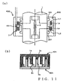
- Fig. 1(a) is a partly-sectional side view schematically showing an embodiment of a relative rotational position detection apparatus in accordance with a first aspect of the present invention.
- the embodiment of the relative rotational position detection apparatus is constructed as a torque detection apparatus 4 for detecting torsional torque acting on a torsion bar 3 of a steering shaft connected to a steering wheel of a motor vehicle. Note that, in Fig. 1(a) and other sectional or partly-sectional schematic views in the accompanying drawings, no hatching is used to indicate sectional surfaces.
- the instant embodiment of the relative rotational position detection apparatus (torque detection apparatus 4) is described here as applied as a torque sensor for detecting torsional torque acting on the torsion bar 3 of the power steering mechanism, the present invention is not so limited, and the relative rotational position detection apparatus of the present invention is of course applicable to all relative rotational position detection applications.
- the instant embodiment of the relative rotational position detection apparatus comprises a first magnetic body section (also referred to as “input shaft rotor") 10 provided for rotation in intercoupled relation to rotation of the input shaft 1, a second magnetic body section (also referred to as “output shaft rotor”) 20 provided for rotation in intercoupled relation to rotation of the output shaft 2, and a coil section 30.
- the first magnetic body section (input shaft rotor) 10 and the second magnetic body section (output shaft rotor) 20 are opposed to each other in a noncontact fashion via an appropriate airgap.
- Fig. 1(b) is a schematic side view showing details of the first magnetic body section (input shaft rotor) 10 and second magnetic body section (output shaft rotor) 20.
- the first magnetic body section (input shaft rotor) 10 comprises a cylindrical member having a plurality of magnetic teeth 1a, 1b, 1c, 1d, ... formed at unequal pitches along the circumferential direction thereof.
- the second magnetic body section (output shaft rotor) 20 comprises a cylindrical member having a plurality of magnetic teeth 2a, 2b, 2c, 2d, ... formed at unequal pitches along the circumferential direction thereof.
- the first magnetic body section (input shaft rotor) 10 is mounted on the input shaft 1 and rotates together with the input shaft 1.
- the second magnetic body section (output shaft rotor) 20 is mounted on the output shaft 2 and rotates together with the output shaft 2.
- the plurality of magnetic teeth 1a, 1b, 1c, 1d, ... of the first magnetic body section (input shaft rotor) 10 form four groups a - d, and the magnetic teeth 1a, 1b, 1c, 1d, ... differ in axial length among the groups.
- the plurality of magnetic teeth 2a, 2b, 2c, 2d, ... of the second magnetic body section (output shaft rotor) 20 form four groups a - d, and the magnetic teeth 2a, 2b, 2c, 2d, ... differ in axial length among the groups each of the four groups.
- Each pair of the magnetic teeth 1a, 1b, 1c, 1d, ... of the first magnetic body section (input shaft rotor) 10 and the magnetic teeth 2a, 2b, 2c, 2d, ... of the second magnetic body section (output shaft rotor) 20 opposed to the teeth 1a, 1b, 1c, 1d, ... have complementary lengths so that the magnetic teeth of each of the pairs of the 1a, 1b, 1c, 1d, ... and 2a, 2b, 2c, 2d, ... are opposed to each other with a predetermined airgap.
- variable magnetic coupling boundary sections there are formed four variable magnetic coupling boundary sections, between the first magnetic body section 10 and the second magnetic body section 20, in corresponding relation to the four groups a - d, and these four variable magnetic coupling boundary sections assume positions offset from one another in the axial direction.
- the above-mentioned coil section 30 comprises four coils L1, L2, L3 and L4 wound around the four variable magnetic coupling boundary sections formed between the magnetic teeth 1a, 1b, 1c, 1d, ... and 2a, 2b, 2c, 2d, ... of the individual groups a - d of the first and second magnetic body sections 10 and 20.
- the coils L1 - L4 are axially spaced apart from one another in correspondence with offset intervals between the four boundary sections, and the four boundary sections, formed between the magnetic teeth 1a, 1b, 1c, 1d, ... and 2a, 2b, 2c, 2d, ... of the first and second magnetic body sections 10 and 20, are inserted in the inner spaces of the corresponding coils L1 - L4.
- the unequalness in positional arrangement (pitch) of the magnetic teeth 1a, 1b, 1c, 1d, ... and 2a, 2b, 2c, 2d, ... of the first and second magnetic body sections 10 and 20 has predetermined regularity such that variation in the magnetic coupling occurring in the individual boundary sections assumes predetermined phase relationship in accordance with a relative rotational position between the input shaft 1 and the output shaft 2.
- Fig. 2(a) shows exemplary correspondency between the magnetic teeth 1a, 1b, 1c, 1d, ... of the first magnetic body section 10 and the magnetic teeth 2a, 2b, 2c, 2d, ... of the second magnetic body section 20 when the shift amount (i.e., relative rotational position), in the clockwise direction, of the input shaft 1 with respect to the output shaft 2 is the maximum (e.g., +7 degrees).
- Fig. 2(b) shows exemplary correspondency between the magnetic teeth 1a, 1b, 1c, 1d, ... of the first magnetic body section 10 and the magnetic teeth 2a, 2b, 2c, 2d, ...
- FIG. 2(c) shows exemplary correspondency between the magnetic teeth 1a, 1b, 1c, 1d, ... of the first magnetic body section 10 and the magnetic teeth 2a, 2b, 2c, 2d, ... of the second magnetic body section 20 when the shift amount (i.e., relative rotational position), in the counterclockwise direction, of the input shaft 1 with respect to the output shaft 2 is the maximum (e.g., -7 degrees).
- the magnetic tooth 1a of the first magnetic body section 10 and the magnetic tooth 2a of the second magnetic body section 20 opposed to each other via a gap, exactly align (i.e., exactly overlap) with each other as seen in each of the boundary sections formed by the magnetic teeth 1a and 2a, belonging to the group a, of the first and second magnetic body sections 10 and 20, the magnetic coupling degree in that boundary section presents the maximum value, which may be regarded as corresponding to a value of sin90° if converted, for example, into a sine function value.
- the magnetic coupling degree in that boundary section presents the minimum value, which may be regarded as corresponding to a value of sin270° or -sine90° if converted, for example, into a sine function value.
- the magnetic coupling variation in the boundary section formed by the magnetic teeth 1a and 2a, belonging to the group a, of the first and second magnetic body sections 10 and 20 and the magnetic coupling variation in the boundary section formed by the magnetic teeth 1c and 2c, belonging to the group c, of the first and second magnetic body sections 10 and 20 assume mutually-opposite phase relationship.
- the magnetic tooth 1b of the first magnetic body section 10 and the magnetic tooth 2b of the second magnetic body section 20 opposed to each other via a gap, overlap with each other by an amount corresponding exactly to one half (1/2) of a horizontal tooth width as seen in each of the boundary sections formed by the magnetic teeth 1b and 2b, belonging to the group b, of the first and second magnetic body sections 10 and 20 in the illustrated example of Fig. 2(a)
- the magnetic coupling degree in that boundary section presents a middle value between the maximum value and the minimum value, which may be regarded as corresponding to a value of cos90° if converted, for example, into a sine function value.
- the magnetic tooth 1d of the first magnetic body section 10 and the magnetic tooth 2d of the second magnetic body section 20 opposed to each other via a gap, overlap with each other by an amount corresponding exactly to one half (1/2) of the horizontal tooth width, in an opposite phase to the aforementioned, in each of the boundary sections formed by the magnetic teeth 1d and 2d, belonging to the group d, of the first and second magnetic body sections 10 and 20 in the illustrated example of Fig. 2(a) , the magnetic coupling degree in that boundary section presents a middle value between the maximum and minimum values, which may be regarded as corresponding to a value of -cos90° if converted, for example, into a sine function value.
- the magnetic teeth 1a and 2a, belonging to the group a, of the first and second magnetic body sections 10 and 20 overlap with each other by an amount corresponding to about three-fourths (3/4) of the horizontal tooth width, and the magnetic coupling degree in the boundary section corresponds to a value of sin45° if converted into a sine function value.
- the magnetic teeth 1c and 2c, belonging to the group c, of the first and second magnetic body sections 10 and 20 overlap with each other by an amount corresponding to about one-fourth (1/4) of the horizontal tooth width, and the magnetic coupling degree in the boundary section corresponds to a value of -sin45° if converted into a sine function value.
- the magnetic teeth 1b and 2b, belonging to the group b, of the first and second magnetic body sections 10 and 20 overlap with each other by an amount corresponding to about three-fourths (3/4) of the horizontal tooth width, and the magnetic coupling degree in the boundary section corresponds to a value of cos45° if converted into a sine function value.
- the magnetic teeth 1d and 2d, belonging to the group d, of the first and second magnetic body sections 10 and 20 overlap with each other by an amount corresponding to about one-fourth (1/4) of the horizontal tooth width, and the magnetic coupling degree in the boundary section corresponds to a value of -cos45° if converted into a sine function value.
- the magnetic teeth 1a and 2a, belonging to the group a, of the first and second magnetic body sections 10 and 20 overlap with each other by an amount corresponding to one half (1/2) of the horizontal tooth width, and the magnetic coupling degree in the boundary section corresponds to a value of sin0° if converted into a sine function value.
- the magnetic teeth 1c and 2c, belonging to the group c, of the first and second magnetic body sections 10 and 20 overlap with each other by an amount corresponding to one half of the horizontal tooth width and in an opposite phase to the above-mentioned, and the magnetic coupling degree in the boundary section corresponds to a value of -sin0° if converted into a sine function value.
- the magnetic teeth 1b and 2b, belonging to the group b, of the first and second magnetic body sections 10 and 20 exactly overlap with each other, and the magnetic coupling degree in the boundary section corresponds to a value of cos0° if converted into a sine function value.
- the magnetic teeth 1c and 2c, belonging to the group c, of the first and second magnetic body sections 10 and 20 are displaced from each other by an amount corresponding exactly to the horizontal tooth width (namely do not at all overlap with each other), and the magnetic coupling degree in the boundary section corresponds to a value of -cos0° if converted into a sine function value.
- relative rotational positions (torsion amounts of the torsion bar 3) over a range of about 14 degrees from the maximum counterclockwise shift amount (about -7 degrees) to the maximum clockwise shift amount clockwise direction (about +7 degrees) between the input shaft 1 and the output shaft 2 appear as magnetic coupling variation in a range of about 90° , i.e. from sin0° to sin90° (or from -sin0° to -sin90°, from cos0° to cos90° or from -cos0° to -cos90°) in terms of the sine function value.
- sin0° to sin90° or from -sin0° to -sin90°, from cos0° to cos90° or from -cos0° to -cos90°
- the individual coils L2, L1, L4 and L3 of the coil section 30 are energized by a common reference A.C. signal (e.g., sin ⁇ t).
- A.C. signal e.g., sin ⁇ t
- impedance of the coils L2, L1, L4 and L3 corresponding to the boundary sections varies.
- the impedance variation can be expressed in a range of about 90 degrees if converted to a sine function value as regards the relative rotational position (torsion amount of the torsion bar 3) over the about-40° range.
- detecting a phase value ⁇ of the sine function value, indicative of the impedance variation corresponding to the relative rotational position (torsion amount of the torsion bar 3) can make absolute detection of the relative rotational position, i.e. torsion amount.
- the impedance variation can be expressed as follows, using an angular variable ⁇ in an angular range of about 90 degrees.
- Fig. 3 shows an example of electric circuitry applicable to the relative-rotational-position detection apparatus (torque detection apparatus 4) of Fig. 1 .
- each of the coils L1 - L4 is shown equivalently as a variable inductance element.
- the coils L1 - L4 are energized in a single phase by a predetermined high-frequency A.C. signal (for convenience sake, indicated by sin ⁇ t) supplied from a reference A.C. signal source 40.
- A.C. signal for convenience sake, indicated by sin ⁇ t
- voltages Va, Vb, Vc and Vd that are produced in the coils L1 - L4, respectively, present intensity corresponding to the impedance values of the individual magnetic teeth groups a - d.
- Analog arithmetic operator 31 calculates a difference between the output voltage Va of the coil L1 corresponding to the sine phase and the output voltage Vc of the coil L3 corresponding to the minus sine phase varying differentially relative to the output voltage Va and thereby generates an output A.C. signal having an amplitude coefficient of a sine function characteristic of the angular variable ⁇ , as expressed below.
- Analog arithmetic operator 32 calculates a difference between the output voltage Vb of the coil L2 corresponding to the cosine phase and the output voltage Vd of the coil L4 corresponding to the minus cosine phase varying differentially relative to the output voltage Vb and thereby generates an output A.C. signal having an amplitude coefficient of a cosine function characteristic of the angular variable ⁇ , as expressed below.
- Fig. 2(d) is a graph of the amplitude coefficient or amplitude function (sin ⁇ ) of the sine function characteristic and amplitude coefficient or amplitude function (cos cos ⁇ ) of the cosine function characteristic of the output A.C. signals provided by the analog arithmetic operators 31 and 32 in the aforementioned manner.
- Fig. 2(e) is a graph schematically showing a manner in which a relative rotational position (i.e., torsion amount or torque of the torsion bar 3) is detected by measuring the phase ⁇ (having a value in a range of about 90 degrees) on the basis of the individual output A.C. signals having amplitude functions as shown in Fig. 2(d) .
- the relative rotational position is detected on the basis of the two output A.C. signals "sin ⁇ sin ⁇ t" and "cos ⁇ sin ⁇ t” produced by the arithmetic operators 31 and 32 using the phase detection scheme.
- the phase detection scheme there may be used the technique disclosed in Japanese Patent Application Laid-open Publication No. HEI-9-126809 .
- an A.C. signal sin ⁇ cos ⁇ t is generated by a shift circuit 33 shifting one of the output A.C. signals, sin ⁇ sin ⁇ t, by an electrical angle of 90 degrees.
- additive synthesis is performed, via an analog adder 34, between the thus-generated A.C. signal sin ⁇ cos ⁇ t and the other output A.C.
- subtractive synthesis is performed, via an analog subtracter 36, between the A.C. signal sin ⁇ cos ⁇ ts output from the shift circuit 33 and the other output A.C. signal cos ⁇ sin ⁇ t, so as to generate an A.C. signal sin( ⁇ t - ⁇ ) phase-shifted in a minus (or phase-retarding) direction in accordance with the angular variable ⁇ (i.e., signal with the phase component ⁇ converted to an A.C. phase shift amount). Then, a zero-cross point of the phase-retarded A.C. signal sin(wt - ⁇ ) is detected by a filter/comparator 37, to generate a zero-cross detection pulse Lm.
- the zero-cross detection pulse Lp of the phase-advanced A.C. signal, output from the comparator 35, is a time signal that indicates the phase shift amount ⁇ of the phase-advanced A.C. signal sin( ⁇ t + ⁇ ), i.e. relative rotational position between the input shaft 1 and the output shaft 2, as an advanced time position from a zero-phase time point of the reference A.C. signal sin ⁇ t.
- the zero-cross detection pulse Lm of the phase-retarded A.C. signal, output from the comparator 37, is a time signal that indicates the phase shift amount ⁇ of the phase-retarded A.C. signal sin ⁇ t - ⁇ ), i.e. relative rotational position between the input shaft 1 and the output shaft 2, as a retarded time position from the zero-phase time point of the reference A.C. signal sin ⁇ t.
- each of the zero-cross detection pulse Lp of the phase-advanced A.C. signal and zero-cross detection pulse Lm of the phase-retarded A.C. signal is detection data indicating, by a time position, a phase shift amount ⁇ corresponding to a relative rotational position between the input shaft 1 and the output shaft 2. Therefore, in principle, it is only necessary to output, as a detection signal of the relative rotational position, either the zero-cross detection pulse Lp of the phase-advanced A.C. signal or zero-cross detection pulse Lm of the phase-retarded A.C. signal.
- a circuit unit 7 further includes a PWM conversion circuit 71 for forming a variable pulse width signal PWM having a pulse width corresponding to a time difference ⁇ t between the zero-cross detection pulse Lp of the phase-advanced A.C. signal and the zero-cross detection pulse Lm of the phase-retarded A.C. signal.
- FIG. 4 shows an example general setup of a system where the embodiment of the detection apparatus 4 of Figs. 1 and 3 housed in the sensor case 41 is connected to a microcomputer 8 that uses detection outputs from the detection apparatus 4.
- the microcomputer 8 includes an input port for capturing a PWM signal, and the above-mentioned output line 7c is connected to the input port.
- the microcomputer 8 counts a pulse time width ⁇ t of the PWM signal from the output line 7c connected to the input port, to thereby digitally measure a relative rotational position between the input shaft 1 and the output shaft 2.
- the thus-measured relative rotational position data is used as torsion angle detection data of the torsion bar 3 for power steering control purposes.
- the instant example circuit construction requires only one output line 7c and thus can be significantly simplified.
- the microcomputer 8 only has to count the pulse time width ⁇ t of the PWM signal from the output line 7c (i.e., time difference ⁇ t between the pulses Lp and Lm), and it is not necessary for the microcomputer 8 to know zero-phase time points of the reference A.C. signal sin ⁇ t used in the detection apparatus. As a consequence, processing and structure for measuring the time in the computer side can be simplified.
- the detection apparatus only has to generate the reference A.C. signal sin ⁇ t inside the apparatus by means of an analog oscillation circuit or the reference A.C. signal oscillation circuit 40 comprising a sine wave function generator or the like.
- the detection apparatus does not have to give the microcomputer 8 the reference A.C. signal sin ⁇ t sin ⁇ t as a synchronizing reference signal, in which regard too the construction of external terminals can be simplified.
- the respective phase shift values ⁇ in the zero-cross detection pulse Lp of the phase-advanced A.C. signal and zero-cross detection pulse Lm of the phase-retarded A.C. signal will include errors ⁇ due to the temperature drift characteristics. Because the errors ⁇ appear in both of the detection signals Lp and Lm in the same value and in the same direction (same sign), these errors ⁇ will be automatically cancelled out in the time difference ⁇ t between the two detection pulses Lp and Lm (time signals). Thus, the instant embodiment can perform high-accuracy detection of the relative rotational position without being influenced by the impedance variation in the circuit etc. due to a temperature drift.
- Fig. 6 is a timing chart schematically showing how the temperature drift compensation is carried out.
- (a) shows example timing for generating the detection pulses Lp and Lm (time signals) in a case where there is no error ⁇ caused by a temperature drift; in this instance, a time difference ⁇ t is 2 ⁇ in theory and represents an accurate relative rotational position.
- (b) shows example timing for generating the detection pulses Lp and Lm (time signals) in a case where there are errors ⁇ caused by a temperature drift. In this case, the detection pulse Lp of the phase-advanced A.C.
- the detection pulse Lm of the phase-retarded A.C. signal is generated at timing later than the zero-phase time point by a retard time equal to "- ⁇ - ⁇ " including the error ⁇ .
- the two detection pulses Lp and Lm include the errors ⁇ as noted above, the errors ⁇ automatically cancel each other in the time difference ⁇ t, so that the time difference ⁇ t corresponds to the theoretical value 2 ⁇ indicative of an accurate relative rotational position.
- appropriate temperature drift compensation can be achieved.
- Fig. 5 shows another example construction employed in the circuit unit 7.
- the zero-cross detection pulse Lp of the phase-advanced signal and the zero-cross detection pulse Lm of the phase-retarded signal are output via two output lines 7a and 7b.
- the microcomputer 8 has a plurality of input ports for capturing time signals, and the above-mentioned output lines 7a and 7b are connected to the input ports, respectively.
- the microcomputer 8 counts a time difference A t between the two time signals (pulses Lp and Lm), to thereby digitally measure a relative rotational position between the input shaft 1 and the output shaft 2.
- the microcomputer 8 counts a pulse time width ⁇ t of the PWM signal from the output line 7c connected to the input port, to thereby digitally measure a relative rotational position between the input shaft 1 and the output shaft 2.
- the thus-measured relative rotational position data is used as torsion angle detection data for power steering control.
- Fig. 7 shows example arrangements for improving the magnetic response sensitivity of the variable magnetic coupling boundary sections formed between the magnetic teeth 1a - 1d and 2a - 2d of the individual groups a - d of the first and second magnetic body sections 10 and 20. More specifically, Fig. 7 (a) is a side view showing an example where a distal end portion (i.e., end portion adjoining the airgap) 1aA or 2aA of each of the magnetic teeth 1a and 2a has a greater thickness than the remaining portion; with such arrangements, the magnetic response sensitivity can be improved as compared to a case where both the distal end portion and the remaining portion have the same thickness.
- Fig. 7 shows example arrangements for improving the magnetic response sensitivity of the variable magnetic coupling boundary sections formed between the magnetic teeth 1a - 1d and 2a - 2d of the individual groups a - d of the first and second magnetic body sections 10 and 20. More specifically, Fig. 7 (a) is a side view showing an example where a distal end
- FIG. 7(b) is a side view showing example arrangements where the distal end portion (i.e., end portion adjoining the airgap) 1aA or 2aA of each of the magnetic teeth 1a and 2a is formed of a magnetic substance while the remaining portion is formed of a nonmagnetic substance; with such arrangements, the magnetic response sensitivity can be improved as compared to a case where both the distal end portion and the remaining portion are formed of the same magnetic substance.
- Fig. 7(c) is a plan view showing example arrangements where the distal end portion (i.e., end portion adjoining the airgap) 1aA, 2aA or 1aB, 2aB of each of the magnetic teeth 1a and 2a has the same horizontal width as the remaining portion.
- Fig. 7(c) is a plan view showing example arrangements where the distal end portion (i.e., end portion adjoining the airgap) 1aA, 2aA or 1aB, 2aB of each of the magnetic teeth 1a and 2a
- FIG. 7(d) is a plan view showing example arrangements where the distal end portion (i.e., end portion adjoining the airgap) 1aA, 2aA or 1aB, 2aB of each of the magnetic teeth 1a and 2a has a greater horizontal width than the remaining portion; such arrangements can enhance the magnetic response sensitivity as compared to the arrangements of Fig. 7(c) .
- Fig. 8 shows another embodiment of the present invention with arrangements simplified as compared to the embodiment in Fig. 1 .
- Fig. 8(a) is a partly-sectional side view schematically showing the other embodiment of the detection apparatus 401.
- Fig. 8(b) is a schematic side view showing details of a first magnetic body section (input shaft rotor) 101 and second magnetic body section (output shaft rotor) 201.
- the first magnetic body section 101 comprises a cylindrical member having a plurality of magnetic teeth 1s, 1c, ... formed at unequal pitches along the circumferential direction thereof and corresponding to two groups s and c.
- the second magnetic body section (output shaft rotor) 201 comprises a cylindrical member having a plurality of magnetic teeth 2s, 2c, ... formed at unequal pitches along the circumferential direction thereof and corresponding to two groups s and c.
- each pair of the magnetic teeth 1s, 1c, ... of the first magnetic body section (input shaft rotor) 101 and the magnetic teeth 2s, 2c, ... of the second magnetic body section (output shaft rotor) 201, opposed to the magnetic teeth 1s, 1c, ... have complementary lengths.
- a coil section 301 comprises a coil L1 wound around a variable magnetic coupling boundary section formed between the magnetic teeth 1s and 2s of the group s of the first and second magnetic body sections 101 and 201, and a coil L2 wound around a variable magnetic coupling boundary section formed between the magnetic teeth 1c and 2c of the group.
- the embodiment of Fig. 8 is simple in construction; that is, the embodiment of Fig. 8 is characterized by the simplified construction of the magnetic teeth 1s, 1c, ..., 2s, 2c, ... reduced number of (i.e., two) coils of the coil section 301.
- the unequalness in arrangement (pitch) of the magnetic teeth 1s, 1c, ... and 2s, 2c,... of the first and second magnetic body sections 101 and 201 has predetermined regularity such that, as in the above-described first embodiment, variation in magnetic coupling occurring in the individual boundary sections assumes predetermined phase relationship in correspondence with a relative rotational position between the input shaft 1 and the output shaft 2.
- the correspondency between the magnetic teeth of the first and second magnetic body sections 101 and 201 varies in response to variation in the relative rotational position between the input shaft 1 and the output shaft 2
- the phases of variation in magnetic coupling degree in the boundary sections corresponding to the groups s and c will differ as follows.
- Fig. 9(a) shows exemplary correspondency between the magnetic teeth 1s and 1c of the first magnetic body section 101 and the magnetic teeth 2s and 2c of the second magnetic body section 201 when the shift amount (i.e., relative rotational position), in the clockwise direction, of the input shaft 1 with respect to the output shaft 2 is the maximum (e.g., +7 degrees).
- Fig. 9(b) shows exemplary correspondency between the magnetic teeth 1s and 1c of the first magnetic body section 101 and the magnetic teeth 2s and 2c of the second magnetic body section 201 when the shift amount (i.e., relative rotational position) of the input shaft 1 with respect to the output shaft 2 is zero (representing the neutral position).
- Fig. 9(b) shows exemplary correspondency between the magnetic teeth 1s and 1c of the first magnetic body section 101 and the magnetic teeth 2s and 2c of the second magnetic body section 201 when the shift amount (i.e., relative rotational position) of the input shaft 1 with respect to the output shaft 2 is zero (representing the
- the magnetic tooth 1s of the first magnetic body section 101 and the magnetic tooth 2s of the second magnetic body section 201 opposed to each other via a gap, exactly align (i.e., exactly overlap) with each other in each of the boundary sections formed by the magnetic teeth 1s and 2s, belonging to the group s, of the first and second magnetic body sections 101 and 201, the magnetic coupling degree in that boundary section presents the maximum value, which may be regarded as corresponding to a value of sin90° if converted, for example, into a sine function value.
- the magnetic coupling degree in that boundary section presents the minimum value, which may be regarded as corresponding to a value of cos90° if converted, for example, into a sine function value.
- the magnetic coupling variation in each of the boundary sections formed by the magnetic teeth 1s and 2s, belonging to the group s, of the first and second magnetic body sections 101 and 201 and the magnetic coupling variation in each of the boundary sections formed by the magnetic teeth 1c and 2c, belonging to the group c, of the first and second magnetic body sections 101 and 201 can be associated with relationship of sine and cosine shifted in phase from each other by 90 degrees.
- the magnetic teeth 1s and 2s, belonging to the group s, of the first and second magnetic body sections 101 and 201 overlap with each other by an amount corresponding to about one half (1/2) of the horizontal tooth width, and the magnetic coupling degree in the boundary section corresponds to a value of sin45° if converted into a sine function value.
- the magnetic teeth 1c and 2c, belonging to the group c, of the first and second magnetic body sections 101 and 201 overlap with each other by an amount corresponding to about one half (1/2) of the horizontal tooth width, and the magnetic coupling degree in the boundary section corresponds to a value of cos45° if converted into a sine function value.
- the magnetic teeth 1s and 2s, belonging to the group s, of the first and second magnetic body sections 101 and 201 are shifted (i.e., do not overlap with) from each other by an amount corresponding exactly to the horizontal tooth width, and the magnetic coupling degree in the boundary section corresponds to a value of sin0° if converted into a sine function value.
- the magnetic teeth 1c and 2c, belonging to the group c, of the first and second magnetic body sections 101 and 201 exactly align or overlap with each other, and the magnetic coupling degree in the boundary section corresponds to a value of cos0° if converted into a sine function value.
- the relative rotational position (torsion amount of the torsion bar 3) over a range of about 14 degrees from the maximum counterclockwise shift amount (about -7 degrees) to the maximum clockwise shift amount clockwise direction (about +7 degrees) between the input shaft 1 and the output shaft 2 appears as magnetic coupling variation in a range of about 90 degrees, i.e. from sin0° to sin90° (or from cos0° to cos90°) in terms of the sine function value.
- the magnetic coupling variation by means of the coil section 301, it is possible to detect the relative rotational position (torsion amount of the torsion bar 3).
- the individual coils L1 and L2 of the coil section 301 are energized by a common reference A.C. signal (e.g., sin ⁇ t).
- A.C. signal e.g., sin ⁇ t
- impedance of the coils L1 and L2 corresponding to the boundary sections varies.
- the impedance variation can be expressed by a range of about 90 degrees if converted into a sine function value as regards the relative rotational position (torsion amount of the torsion bar 3) in the range of about 14 degrees.
- detecting a phase value ⁇ of the sine function value, indicative of the impedance variation corresponding to the relative rotational position (torsion amount of the torsion bar 3), can make absolute detection of the relative rotational position, i.e. torsion amount.
- the impedance variation can be expressed as follows, using an angular variable ⁇ in the angular range of about 90 degrees.
- Fig. 10 shows an example of electric circuitry applicable to the relative-rotational-position detection apparatus (torque detection apparatus 401) of Fig. 8 .
- each of the coils L1and L2 is shown equivalently as a variable inductance element.
- the coils L1 and L2 are energized in a single phase by a predetermined high-frequency A.C. signal (sin ⁇ t) supplied from a reference A.C. signal source 40.
- voltages Va and Vc that are produced in the coils L1 and L2, respectively, present intensity corresponding to the impedance values of the individual groups s and c.
- Vs P 0 + sin ⁇ ⁇ sin ⁇ t
- Vc P 0 + cos ⁇ ⁇ sin ⁇ t
- the circuitry of Fig. 10 includes voltage-dividing resistors R1 and R2 for producing a predetermined reference A.C. voltage Vr.
- Analog arithmetic operator 31 subtracts the reference A.C. voltage Vr from the output voltage Va of the coil L1 corresponding to the sine phase and thereby generates an output A.C. signal having an amplitude coefficient of a sine function characteristic of an angular variable ⁇ , as expressed below.
- Analog arithmetic operator 32 subtracts the reference A.C. voltage Vr from the output voltage Vc of the coil L2 corresponding to the cosine phase and thereby generates an output A.C. signal having an amplitude coefficient of a cosine function characteristic of an angular variable ⁇ , as expressed below.
- FIG. 9(d) is a graph which, similarly to Fig. 2(d) , shows the amplitude coefficient or amplitude function (sin ⁇ ) of the sine function characteristic and amplitude coefficient or amplitude function (cos ⁇ ) of the cosine function characteristic of the output A.C.
- Fig. 9(e) is a graph which, similarly to Fig. 2(e) , schematically shows a manner in which a relative rotational position (i.e., torsion amount or torque of the torsion bar 3) is detected by measuring a phase ⁇ (having a value in a range of about 90 degrees) on the basis of the individual output A.C. signals having amplitude functions as shown in Fig. 9(d) .
- Other circuits in Fig. 10 are similar to those shown in Fig.
- Means for generating the reference A.C. voltage Vr is not limited to the one based on the voltage-dividing resistors R1 and R2, and the reference A.C. voltage Vr may be generated via a coil of constant impedance (i.e., coil whose impedance does not vary in accordance with the phase ⁇ and which is of course energized by an A.C. voltage, sin ⁇ t). Namely, the voltage-dividing resistor R1 may be replaced with a constant-voltage generating coil.
- Figs. 11 - 13 show a modification of the embodiment of Figs. 8 - 10 .
- the modified embodiment of Figs. 11 - 13 is different in construction from the embodiment of Figs. 8 - 10 in that a coil section 302 includes two sets of coils L1, Ls and L2, Lc in corresponding relation to variable magnetic coupling boundary sections of groups s and c; in other respects, the modified embodiment of Figs. 11 - 13 is similar in construction to the embodiment of Figs. 8 - 10 . Namely, two coils L1 and Lc are wound in correspondence with the boundary section of the group s, while two coils L2 and Ls are wound in correspondence with the boundary section of the group c.
- main coils L1 and L2 corresponding to the groups s and c are wound for the boundary sections of the groups s and c, and sub-coils Lc and Ls corresponding to the other groups c and s are wound on the outer periphery of the main coils L1 and L2, respectively.
- the coils L1 and Ls are wound in a pair, and respective numbers of turns (i.e., respective inductance) of the coils L1 and Ls are set such that impedance variation thereof presents a sine function characteristic in a range of about 90 degrees in correspondence with a maximum moving range shown in Fig. 12(a) - (c) .
- the coils L2 and Lc are wound in a pair, and respective numbers of turns (i.e., respective inductance) of the coils L2 and Lc are set such that impedance variation thereof presents a cosine function characteristic over a range of about 90 degrees in correspondence with the maximum moving range shown in Fig. 12(a) - (c) .
- the magnetic tooth 1s of the first magnetic body section 101 and the magnetic tooth 2s of the second magnetic body section 201 opposed to each other via a gap, exactly align (i.e., exactly overlap) with each other in each of the boundary sections formed by the magnetic teeth 1s and 2s, belonging to the group s, of the first and second magnetic body sections 101 and 201, and the magnetic coupling degree in that boundary section presents the maximum value, which may be regarded as corresponding to a value of sin90° if converted, for example, into a sine function value.
- the number of turns N of the main coil L1 is set such that the impedance of the corresponding main coil L1 takes a value corresponding to sin90° (e.g., "2a + b").
- the magnetic teeth 1c and 2c, belonging to the group c, of the first and second magnetic body sections 101 and 201 in the illustrated example of Fig. 12(a) are shifted from each other by an amount corresponding exactly to the horizontal tooth width (namely do not at all overlap with each other), and the magnetic coupling degree in the boundary section presents the minimum value.
- the number of turns N of the main coil L2 is set such that the impedance of the corresponding main coil L2 takes a value corresponding to cos90° (e.g., "a + b").
- the number of turns n of the sub-coil Ls of the group s is set such that the impedance of the sub-coil Ls takes a value corresponding to -sin90° (e.g., "b") when the magnetic coupling degree is of the minimum value.
- the number of turns n of the sub-coil Lc of the group c, provided in association with the boundary section formed by the magnetic teeth 1s and 2s of the group s, is set such that the impedance of the sub-coil Lc takes a value corresponding to -cos90° (e.g., "a + b") when the magnetic coupling degree is of the maximum value.
- the impedance variation can be expressed as follows, using an angular variable ⁇ in the angular range of about 90 degrees, from 0 to 90 degrees.
- Fig. 13 shows an example of electric circuitry applicable to the relative-rotational-position detection apparatus (torque detection apparatus 402) of Fig. 11 , which is substantially similar in construction to the electric circuitry of Fig. 3 .
- the coils L3 and L4 are replaced with the sub-coils Ls and Lc; however, because both the coils L3 and L4 and the sub-coils Ls and Lc theoretically present impedance variation C( ⁇ ) and D( ⁇ ) of similar characteristics, the explanation made above in relation to Fig. 3 also applies to Fig. 13 as-is.
- Figs. 11 - 13 there can be obtained two output A.C.
- the distal end of one of the opposed magnetic teeth 1a has a flat surface, while the distal end of the other magnetic tooth 2a has a curved surface, such as a sine curve surface.
- a variation curve close to a sine curve or cosine curve
- variation of magnetic coupling degree i.e., impedance variation
- the distal ends of the opposed magnetic teeth 1a and 2a are shaped obliquely, and these oblique surfaces are opposed to each other.
- the gap or distance between the opposed oblique distal end surfaces varies, so that there can be obtained variation of magnetic coupling degree (i.e., impedance variation).
- the magnetic teeth 1a and 2a are opposed to each other at their side surfaces via a gap without their flat distal end surfaces overlapping each other.
- the gap or distance between the opposed side surfaces varies, so that there can be obtained variation of magnetic coupling degree (i.e., impedance variation).
- the thickness between the opposite side surfaces of each of the two magnetic teeth 1a and 2a is increased, the distal end surfaces opposed to each other via the gap can have an increased area, so that the magnetic flux amount can be increased to thereby enhance the magnetic response sensitivity.
- the opposed magnetic teeth 1a and 2a have their respective flat surfaces overlapping each other via a predetermined gap or distance.
- the area of the overlappingly-opposed flat surfaces increases, so that there can be obtained variation of the magnetic coupling degree (impedance variation).
- the increased overlapping area can increase the magnetic flux amount and enhance the magnetic response sensitivity.
- Fig. 15 is a schematic sectional side view showing an embodiment of the relative rotational position detection apparatus in accordance with the second aspect of the present invention.
- a novel detection system which includes, in relation to steering of a motor cycle, detection apparatus of two different functions, i.e. a torque detection apparatus 4A having a function for detecting torsional torque acting on a torsion bar of a steering shaft and a steering angle detection apparatus 4B having a function as a steering angle (steering shaft rotation) sensor; these detection apparatus are integrally accommodated in a cylindrical external case 41.
- the embodiment of the relative rotational position detection apparatus of the present invention is the torque detection apparatus 4A.
- the steering angle detection apparatus 4B which comprises a plurality of gears G1 - G3, stator section 100, rotor section 200, etc., only has to be provided in at least one position.
- the torque detection apparatus 4A and the steering angle detection apparatus 4B may be provided separately rather than integrally within the external case 41.
- the provision of the steering angle detection apparatus 4B is not necessarily essential.
- the relative rotational position detection (torque detection apparatus 4A) of Fig. 15 comprises a first magnetic body section 10 provided to rotate in interlocked relation to rotation of the input shaft 1, a second magnetic body section 20 provided to rotate in interlocked relation to rotation of the output shaft 2, and a coil section 30.
- Mounting ring 5 is attached to the input shaft 1, and the first magnetic body section 10 is mounted on the mounting ring 5. Further, a mounting ring 6 is attached to the output shaft 2, and the second magnetic body section 20 is mounted on the mounting ring 6.
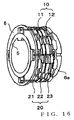
- Fig. 16 is an assembled perspective view extractively showing the first and second magnetic body sections 10 and 20 mounted on the mounting rings 5 and 6.
- Fig. 17 is an exploded perspective view corresponding to Fig. 16 .
- the first magnetic body section 10 comprises a plurality of (two in the illustrated example) first magnetic rings 11 and 12 axially spaced apart from each other.
- the second magnetic body section 20 comprises a plurality of (three in the illustrated example) third magnetic rings 21, 22 and 23 axially spaced apart from each other.
- the magnetic rings 11 and 12 are inserted in a sleeve portion 6a of one of the mounting rings 6 in such a manner that they are positioned alternately between the magnetic rings 21, 22 and 23.
- the magnetic rings 21, 22 and 23 of the second magnetic body section 20, to be rotated with the output shaft 2, are fixed to the mounting ring 6 in predetermined mutual relationship to be later described.
- a plurality of pins 51, 52, 53 and 54 extending in the axial direction to interconnect the magnetic rings 11 and 12 are provided on the mounting ring 5 to be connected to the output shaft 1.
- a sleeve portion 5a of the mounting ring 5 is inserted into the sleeve portion 6a of the mounting ring 6.
- Each of the magnetic rings 21, 22 and 23 associated with the output shaft 2 has a plurality of circumferentially-elongated through-holes SH formed in predetermined positions thereof to allow the connecting pins 51 - 54 of the mounting ring 5, associated with the input shaft, 1 to freely play or escape in the assembled state.
- each of the magnetic rings 11 and 12 associated with the input shaft 1 has a plurality of holes H formed in predetermined positions thereof so that the connecting pins 51 - 54 of the mounting ring 5 associated with the input shaft 1 can be fitted in the holes H in predetermined phase relationship as will be later described.
- the magnetic rings 11 and 12 alternately positioned between the magnetic rings 21, 22 and 23 fixed to the mounting ring 6 associated with the output shaft 2, are connected, via the connecting pins 51 - 54, to the mounting ring 5 associated with the input shaft 1, so that they can rotate together with the input shaft 1.
- the magnetic rings 11 and 12 of the input shaft 1 are freely rotatable relative to the sleeve portion 6a of the mounting ring 6 of the output shaft 2.
- the through-holes SH elongated in the circumferential direction serves to permit rotating movement of the connecting pins 51 - 54 caused by the rotation of the input shaft 1, although the pins 51 - 54 provided on the mounting ring 5 of the input shaft 1 loosely extend through the through-holes SH in each of the magnetic rings 21, 22 and 23 of the output shaft 2; thus, the two shafts 1 and 2 will never be locked by the provision of the connecting pins 51 - 54.
- the escape angle provided by each of the through-holes SH is set to be greater than the maximum angle of the torsion by the torsion bar 3.
- Each of the magnetic rings 11, 12, 21, 22 and 23 is shaped to have a plurality of (eight in the illustrated example) magnetic concave/convex tooth portions (i.e., increase/decrease pattern of magnetic substance) along its circumference.
- concave/convex tooth portions i.e., magnetic increase/decrease pattern
- the above-mentioned coil section 30 comprises four coils L1, L2, L3 and L4 wound around the four variable magnetic coupling boundary sections formed between the magnetic rings 21, 11, 22, 12 and 23 in the assembled state as seen in Fig. 16 .
- the coils L1 - L4 are axially spaced apart at given intervals, and the four boundary sections, formed between the magnetic rings 21, 11, 22, 12 and 23 are inserted in inner spaces of the corresponding coils L1 - L4.
- Fig. 18 is an expansion plan view of the magnetic rings 21, 11, 22, 12 and 23.
- the magnetic rings 21 and 23 are positioned in such a manner that their repetition cycles agree with each other in phase
- the middle magnetic ring 22 is positioned in such a manner that its repetition cycle is phase-shifted by a quarter cycle from the repetition cycles of the magnetic rings 21 and 23. Because these magnetic rings 21, 22 and 23 are fixed to the mounting ring 6 in the above-mentioned predetermined mutual relationship, the predetermined mutual relationship can be constantly maintained despite the rotation of the output shaft 2.
- the magnetic rings 11 and 12 of the first magnetic body section 10 rotatable with the input shaft 10 are positioned to be phase-shifted from each other by one half (1/2) of the repletion cycle of the convex/concave tooth portions (namely, to assume mutually-opposite phases). These magnetic rings 11 and 12 rotate with the input shaft 1 while maintaining such mutual relationship.
- variation phases in the four boundary sections differ, as set forth below, as the correspondency between the concave/convex tooth portions of the adjoining first and second magnetic rings varies in response to variation in the relative rotational position between the input shaft 1 and the output shaft 2.
- the magnetic coupling degree in that boundary section presents the maximum value, which may be regarded as corresponding to a value of sin90° if converted, for example, into a sine function value.
- the convex/concave tooth portions of the magnetic rings, adjoining each other via a gap are phase-shifted by just one half (1/2) of the cycle as seen in each of the boundary sections between the magnetic rings 12 and 23 of Fig.
- the magnetic coupling degree in that boundary section presents the minimum value, which may be regarded as corresponding to a value of sin270° or - sin90 ° if converted, for example, into a sine function value.
- variation of the magnetic coupling in the each of the boundary sections between the magnetic rings 21 and 11 and variation of the magnetic coupling in the each of the boundary sections between the magnetic rings 12 and 23 assume mutually-opposite phase relationship.
- the convex/concave tooth portions of the magnetic rings, adjoining each other via a gap are phase-shifted by just one-fourth (1/4) of the cycle as seen in each of the boundary sections between the magnetic rings 11 and 12 of Fig.
- the magnetic coupling degree in that boundary section presents a middle value between the maximum and minimum values, which may be regarded as corresponding to a value of cos90° if converted, for example, into a sine function value.
- the convex/concave tooth portions of the magnetic rings, adjoining each other via a gap are shifted from each other by just one-fourth (1/4) of the cycle in opposite phase to the above-mentioned as seen in each of the boundary sections between the magnetic rings 22 and 12 of Fig. 18 , the magnetic coupling degree in that boundary section presents a middle value between the maximum and minimum values, which may be regarded as corresponding to a value of -cos90° if converted, for example, into a sine function value.
- the individual coils L1 - L4 of the coil section 30 are energized by a common reference A.C. signal (e.g., sin ⁇ t).
- A.C. signal e.g., sin ⁇ t
- impedance of the coils L1 - L4 corresponding to the boundary sections varies.
- the impedance variation occurs with rotational displacement, corresponding to one pitch of the convex/concave tooth portions of the magnetic rings 11 - 23, as one cycle thereof.
- the impedance variation can be expressed as follows, using an angular variable ⁇ based on an angle representation of a high-resolution scale where one pitch width (e.g., about 22 degrees) between the convex/concave tooth portions of the magnetic rings 11 - 23 is set at 360 degrees.
- Fig. 19 shows an example of electric circuitry applicable to the relative-rotational-position detection apparatus (torque detection apparatus 4A) of Fig. 15 , which is substantially similar in construction to the electric circuitry of Fig. 3 and thus will not be described in detail here.
- Figs. 15 - 19 there can be obtained two output A.C. signals "sin ⁇ sin ⁇ t” and “cos ⁇ sin ⁇ t” having been modulated in amplitude with two cyclic amplitude functions (sin ⁇ and cos ⁇ ), respectively, that contain the angular variable ⁇ correlating to a relative rotational position to be detected.
- detection pulses Lp and Lm of phase-advanced and phase-retarded signals indicating the phase angle ⁇ correlating to a relative rotational position to be detected there are generated detection pulses Lp and Lm of phase-advanced and phase-retarded signals indicating the phase angle ⁇ correlating to a relative rotational position to be detected, as well as a variable pulse width signal PWM having a pulse width corresponding to a time difference ⁇ t between the detection pulses Lp and Lm.
- the detection system according to the embodiment shown in Fig. 15 integrally includes not only the function of the torque detection apparatus 4A for detecting torque applied to the torsion bar 3 of the power steering mechanism, but also the function of the steering angle detection apparatus 4B intended for purposes, such as correction of a difference in correspondency between a steering wheel angle corresponding to a rotational operation amount of the steering wheel and steered road wheels.
- the other embodiments shown in Figs. 1 - 13 too may have such a function of the steering angle detection apparatus 4B, in addition to the function of the torque detection apparatus 4.
- the steering angle detection apparatus 4B includes, in respective predetermined positions within the external case 41, a plurality of gears G1 - G3, a stator section 100 and a rotor section 200 including a magnetism-responsive member 300.
- the gears G1 - G3 constitute a gearing mechanism for rotating the rotor section 200 after reducing stepwise the number of rotations of the input shaft 2 coupled to the steering wheel; for example, the gearing mechanism reduces the number of rotations of the output shaft 2 at a predetermined ratio, e.g. one rotation of the rotor section 200 per five rotations of the output shaft 2, so that rotational positions over multiple rotations of the steering wheel can be detected via a one-rotation type absolute sensor.
- Fig. 20 is a schematic view of an embodiment of the steering angle detection apparatus 4B, which particularly shows, in a schematic front view, physical positional relationship between the coils C1 - C4 of the stator section 100 and the magnetism-responsive member 300 formed on the surface of the rotor section 200.
- the magnetism-responsive member 300 of a predetermined shape e.g., eccentric shape
- the stator section 100 includes, as detecting coils, the four coils C1 - C4 (see Fig. 20 ), and magnetic flux passing through the coils C1 - C4 is oriented in the axial direction.
- the stator section 100 and rotor section 200 are positioned in opposed relation to each other in such a manner that predetermined gaps are formed between respective end surfaces of coil cores (e.g., magnetic cores, such as iron cores) for the four coils C1 - C4 of the stator section 100 and the magnetism-responsive member 300 formed on the surface of the rotor section 200, namely, that airgaps are formed between the end surfaces of the coil cores of the four coils C1 - C4 and the magnetism-responsive member 300 formed on the surface of the rotor section 200.
- the rotor section 200 rotates relative to the stator section 100 in a noncontact fashion. Rotational angle of the output shaft, i.e. rotational angle of the steering wheel, can be detected by the area of the end surfaces of the coil cores of the coils C1 - C4, opposed to the magnetism-responsive member 300, varying in response to a rotational position of the rotor section 200.
- coil cores e.g
- the instant embodiment of the steering angle detection apparatus 4B includes a one-rotation type absolute position detecting sensor based on the electromagnetic induction scheme as illustrated in Fig. 20 , a plurality of gears G1 - G3 of different gear ratios sequentially meshing with each other, the stator section 100, and the rotor section 200.
- the plurality of gears G1 - G3 constitute a speed reducing mechanism for rotating the rotor section 200 after reducing stepwise the number of rotations of the output shaft 2 of the steering shaft.
- the gear 1 is coupled to the output shaft 2 and rotates in a similar manner to the output shaft 2, the speed-reducing gear G2 is meshed with the gear G1, and the speed-reducing gear G3 is meshed with the gear G2.
- the rotor section 200 formed for example into a disk shape, is provided on the gear G3 and rotates about the axial centerline CL as the gear G3 rotates. In this manner, the gears G1 - G3 transmit the rotations of the output shaft 2 to the rotor section 200 after reducing the rotation speed.
- the magnetism-responsive member 300 On the surface of the rotor section 200, there are provided the magnetism-responsive member 300 of a predetermined shape, such as an eccentric ring shape as illustratively shown in Fig. 20 .
- the magnetism-responsive member 300 may be formed of any suitable material that can cause a magnetic coupling coefficient to vary, such as a magnetic substance like iron, an electrically-conductive substance like copper, or a combination of such magnetic and electrically-conductive substances.
- the stator section 100 is opposed to the thus-constructed rotor section 200 in a thrust direction.
- the predetermined shape of the magnetism-responsive member 300 formed on the surface of the rotor section 200 is chosen appropriately so as to obtain, from the coils C1 - C4, ideal sine, cosine, minus sine and minus cosine curves.
- the positions of the coils C1- C4 and the shape of the magnetism-responsive member 300 may be set such that, assuming that the impedance variation occurring in the coil C1 represents a sine function, the impedance variation occurring in the coil C2 represents a minus sine function, the impedance variation occurring in the coil C3 represents a cosine function and the impedance variation occurring in the coil C4 represents a minus cosine function.
- the positions of the coils C1- C4 and the shape of the magnetism-responsive member 300 are set such that, per rotation of the rotor section 200, the impedance of the coil C1 varies in a sine function over the range of 0 - 360 degrees, the impedance of the coil C2 varies in a cosine function over the range of 0 - 360 degrees, the impedance of the coil C3 varies in a minus sine function over the range of 0 - 360 degrees and the impedance of the coil C4 varies in a minus cosine function over the range of 0 - 360 degrees.
- the impedance variation of the coils C1 - C4 can be likened to variation in sine and cosine function values over the range of 0 - 360 degrees as noted above, one rotation of the rotor section 200 can be measured by being converted into variation in the 360° range.
- the impedance of the pair of the coils C1 and C3 vary differentially, and an output A.C. signal “sin ⁇ sin ⁇ t” having the sine function "sin ⁇ " as its amplitude coefficient can be obtained by differential synthesis of the respective outputs of the coils C1 and C3.
- the impedance of the other pair of the coils C2 and C4 vary differentially, and an output A.C. signal “cos ⁇ sin ⁇ t" having the cosine function "cos ⁇ " as its amplitude coefficient can be obtained by differential synthesis of the respective outputs of the coils C2 and C4.
- Rotational position can be detected by synthesizing, on the basis of such output signals similar to those of a resolver, an A.C. signal phase-shifted by an amount corresponding to ⁇ and then measuring the phase shift value ⁇ .
- rotational angles, over multiple rotations (e.g., 2.5 - 3 rotations) of the steering wheel can be detected in absolute values by being converted into absolute rotational positions within one rotation of the rotor section 200.
- the predetermined shape of the magnetism-responsive member 300 intended to obtain the sine, cosine, minus sine and minus cosine function curves in the predetermined angular range in response to rotation of the rotor section 200, may be any suitable shape other than the above-mentioned eccentric ring shape, such as a spiral shape, heart-like shape or the like depending on the design settings like the positions, shapes etc. of the coils and coil cores.
- the steering angle detection apparatus 4B is not limited to the above-described construction and may be constructed in any other suitable manner.
- the speed-reducing mechanism constituted by the gears G1 - G3 may be dispensed with, and the rotor section 200 may be coupled to the output shaft 2 (or input shaft 1) at a rotation ratio of 1 : 1.
- the steering angle detection apparatus 4B may be dispensed with.
- the arrangement pattern, numbers, sizes, etc. of the magnetism-responsive member and coils corresponding thereto are not limited to the above-described and various other arrangement patterns etc. are possible; in short, any suitable arrangement pattern etc. of the magnetism-responsive member and coils may be used as long as they allow output signals of two phases (sine and cosine phases) to be produced from the coil section.
- any suitable arrangement pattern etc. of the magnetism-responsive member and coils may be used as long as they allow output signals of two phases (sine and cosine phases) to be produced from the coil section.
- the terms "sine phase” and "cosine phase” used herein are designations selected only for purposes of description, and either one of the two phases may be referred to as the sine phase or cosine phase.
- the rotational position detection means of the phase-shift type is not limited to the above-described construction and may be constructed in any suitable manner.
- the rotational position detection means is not limited to the type having the primary coil alone, and it may be of a type having primary and secondary coils or of a resolver type.
- the number of the concave/convex tooth portions (i.e., number of pitches per rotation) of each of the magnetic rings 11 - 23 may be other than eight as noted above.
- each of the magnetic rings 11 - 23 may be of other than the type having multiple tooth portions, such as a type which causes magnetic coupling variation (i.e., impedance variation of the coil) of one pitch (one cycle) per rotation.
- the construction for causing the magnetic coupling to increase or decrease in response to the rotation may be based on other than the concave/convex tooth portions as used in the illustrated examples, such as tooth portions of a wave shape or other suitable shape.
- the material of the magnetic body sections 10 and 20, i.e. each of the magnetic rings 11 - 23, is not limited to the one consisting of a magnetic substance alone and may alternatively be of a hybrid type of magnetic and diamagnetic substances where the diamagnetic substance (nonmagnetic and good electrically-conductive substance, such as copper) is embedded in a recessed portion (where the magnetic coupling is to be decreased) of the magnetic substance.
- each of the components that should have no magnetism-responsive characteristic is made of a material having no magnetism-responsive characteristic, such as synthetic resin.
- the shapes, materials, etc. of the magnetic body sections 10, 20, 101, 201, 102, 202 may be modified variously similarly to the aforementioned.
Landscapes
- Physics & Mathematics (AREA)
- General Physics & Mathematics (AREA)
- Electromagnetism (AREA)
- Engineering & Computer Science (AREA)
- Chemical & Material Sciences (AREA)
- Combustion & Propulsion (AREA)
- Transportation (AREA)
- Mechanical Engineering (AREA)
- Power Steering Mechanism (AREA)
- Measurement Of Length, Angles, Or The Like Using Electric Or Magnetic Means (AREA)
Abstract
Claims (8)
- Appareil de détection de position de rotation relative pour détecter une position de rotation relative entre des premier et second arbres (1, 2) aptes à tourner l'un par rapport à l'autre, l'appareil de détection de position de rotation relative comprenant :une première section de corps magnétique (10) conçue pour tourner en relation de couplage mutuel avec la rotation du premier arbre (1) ;une seconde section de corps magnétique (20) conçue pour tourner en relation de couplage mutuel avec la rotation du second arbre (2),ladite première section de corps magnétique (10) et ladite seconde section de corps magnétique (20) formant au moins deux sections de délimitation de couplage magnétique variable en forme d'anneau opposées l'une à l'autre ou les unes aux autres par l'intermédiaire d'un espace, un couplage magnétique dans chacune des sections de délimitation de couplage magnétique variant en réponse à une variation de la position de rotation relative entre ledit premier arbre (1) et ledit seconde arbre (2), une variation du couplage magnétique différant en phase entre les sections de délimitation de couplage magnétique ; etune section de bobine (30) comprenant des bobines de détection (L1 - L4) disposées chacune en relation de correspondance avec l'une des sections de délimitation de couplage magnétique,caractérisé par le fait que lesdites première et seconde sections de corps magnétique (10, 20) comprennent chacune un élément cylindrique ayant une pluralité de dents magnétiques formées à pas inégaux le long d'une direction périphérique de celui-ci,
la pluralité de dents magnétiques formant des groupes correspondant à la pluralité de sections de délimitation de couplage magnétique,
les dents magnétiques dans chacune desdites première et seconde sections de corps magnétique (10, 20) différant de par leur longueur axiale parmi les groupes, et
les dents magnétiques de chacun des groupes dans lesdites première et seconde sections de corps magnétique (10, 20) étant opposées les unes aux autres pour former ainsi la section de délimitation de couplage magnétique correspondant au groupe, de telle sorte que les sections individuelles de délimitation de couplage magnétique sont disposées dans des positions axialement décalées les unes par rapport aux autres. - Appareil de détection de position de rotation relative selon la revendication 1, dans lequel l'une des sections de délimitation de couplage magnétique présente une variation de couplage magnétique de caractéristique sinusoïdale en réponse à une variation de la position de rotation relative entre ledit premier arbre et ledit second arbre, et dans lequel une autre des sections de délimitation de couplage magnétique présente une variation de couplage magnétique de caractéristique cosinusoïdale en réponse à une variation de la position de rotation relative entre ledit premier arbre et ledit second arbre.
- Appareil de détection de position de rotation relative pour détecter une position de rotation relative entre des premier et second arbres (1, 2) aptes à tourner l'un par rapport à l'autre, l'appareil de détection de position de rotation relative comprenant :une première section de corps magnétique (10) conçue pour tourner en relation de couplage mutuel avec la rotation du premier arbre (1) ;une seconde section de corps magnétique (20) conçue pour tourner en relation de couplage mutuel avec la rotation du second arbre (2),ladite première section de corps magnétique (10) et ladite seconde section de corps magnétique (20) formant au moins deux sections de délimitation de couplage magnétique variable en forme d'anneau opposées l'une à l'autre ou les unes aux autres par l'intermédiaire d'un espace, un couplage magnétique dans chacune des sections de délimitation de couplage magnétique variant en réponse à une variation de la position de rotation relative entre ledit premier arbre (1) et ledit seconde arbre (2), une variation du couplage magnétique différant en phase entre les sections de délimitation de couplage magnétique ; etune section de bobine (30) comprenant des bobines de détection (L1 - L4) disposées chacune en relation de correspondance avec l'une des sections de délimitation de couplage magnétique,caractérisé par le fait que ladite première section de corps magnétique (10) a une pluralité de premiers anneaux magnétiques (11, 12) espacés axialement les uns des autres,
ladite seconde section de corps magnétique (20) a une pluralité de seconds anneaux magnétiques (21, 22, 23) espacés axialement les uns des autres,
des anneaux magnétiques individuels parmi lesdits seconds anneaux magnétiques (21, 22, 23) sont positionnés de manière alternée entre lesdits premiers anneaux magnétiques (11, 12) et reliés les uns aux autres par l'intermédiaire de moyens de liaison pour une rotation avec ledit second arbre (2) ; et
les surfaces opposées desdits premiers anneaux magnétiques (11, 12) et desdits seconds anneaux magnétiques (21, 22, 23) forment un motif d'augmentation/diminution de substance magnétique, de telle sorte que lesdites sections de délimitation de couplage magnétique sont formées entre des anneaux magnétiques adjacents parmi la pluralité de premiers anneaux magnétiques (11, 12) et la pluralité de seconds anneaux magnétiques (21, 22, 23). - Appareil de détection de position de rotation relative selon la revendication 3, dans lequel quatre sections de délimitation de couplage magnétique précitées sont formées entre des anneaux magnétiques adjacents parmi la pluralité de premiers anneaux magnétiques (11, 12) et la pluralité de seconds anneaux magnétiques (21, 22, 23), et
dans lequel une première section parmi lesdites sections de délimitation de couplage magnétique présente une variation de couplage magnétique de caractéristique sinusoïdale en réponse à une variation de la position de rotation relative entre ledit premier arbre (1) et ledit second arbre (2), une deuxième section parmi lesdites sections de délimitation de couplage magnétique présente une variation de couplage magnétique de caractéristique cosinusoïdale en réponse à une variation de la position de rotation relative entre ledit premier arbre (1) et ledit second arbre (2), une troisième section parmi lesdites sections de délimitation de couplage magnétique présente une variation de couplage magnétique de caractéristique cosinusoïdale négative en réponse à une variation de la position de rotation relative entre ledit premier arbre (1) et ledit second arbre (2), et une quatrième section parmi lesdites sections de délimitation de couplage magnétique présente une variation de couplage magnétique de caractéristique cosinusoïdale négative en réponse à une variation de la position de rotation relative entre ledit premier arbre (1) et ledit second arbre (2). - Appareil de détection de position de rotation relative selon l'une quelconque des revendications 1 - 4, qui comprend en outre un circuit pour synthétiser des signaux de sortie respectifs des bobines de ladite section de bobine, pour permettre ainsi de générer un signal alternatif (C.A.) de sortie déphasé à partir d'un signal alternatif (C.A.) de référence conformément à une position de rotation relative entre ledit premier arbre et ledit second arbre.
- Appareil de détection de position de rotation relative selon l'une quelconque des revendications 1 - 5, dans lequel chacune des bobines de ladite section de bobine est une bobine unique à exciter par un signal alternatif (C.A.) de référence prédéterminé, l'impédance de la bobine unique étant déterminée conformément à un couplage magnétique de la section de délimitation correspondant à ladite bobine, et ladite bobine générant un signal alternatif (C.A.) de sortie ayant une amplitude correspondant à l'impédance.
- Appareil de détection de position de rotation relative selon l'une quelconque des revendications 1 - 6, dans lequel lesdits premier et second arbres sont interconnectés par une barre de torsion, et une amplitude de torsion entre lesdits premier et second arbres est détectée en tant que position de rotation relative.
- Appareil de détection de position de rotation relative selon l'une quelconque des revendications 1 - 7, dans lequel lesdits premier et second arbres sont un arbre d'entrée et un arbre de sortie de direction assistée d'un véhicule motorisé.
Applications Claiming Priority (2)
| Application Number | Priority Date | Filing Date | Title |
|---|---|---|---|
| JP2003305373 | 2003-08-28 | ||
| PCT/JP2004/012381 WO2005022103A1 (fr) | 2003-08-28 | 2004-08-27 | Dispositif de detection d'une position de rotation relative |
Publications (3)
| Publication Number | Publication Date |
|---|---|
| EP1659384A1 EP1659384A1 (fr) | 2006-05-24 |
| EP1659384A4 EP1659384A4 (fr) | 2007-03-21 |
| EP1659384B1 true EP1659384B1 (fr) | 2011-11-30 |
Family
ID=34269298
Family Applications (1)
| Application Number | Title | Priority Date | Filing Date |
|---|---|---|---|
| EP04772337A Active EP1659384B1 (fr) | 2003-08-28 | 2004-08-27 | Dispositif de detection d'une position de rotation relative |
Country Status (4)
| Country | Link |
|---|---|
| US (1) | US7331247B2 (fr) |
| EP (1) | EP1659384B1 (fr) |
| JP (1) | JP4651540B2 (fr) |
| WO (1) | WO2005022103A1 (fr) |
Families Citing this family (7)
| Publication number | Priority date | Publication date | Assignee | Title |
|---|---|---|---|---|
| GB2426591B (en) * | 2005-05-27 | 2009-12-30 | Tt Electronics Technology Ltd | Sensing apparatus and method |
| JP4770308B2 (ja) * | 2005-07-15 | 2011-09-14 | 日立電線株式会社 | トルクセンサ |
| CN201707349U (zh) * | 2010-04-16 | 2011-01-12 | 范雪莲 | 微电磁加速度位移倾角振动传感器 |
| JP5899090B2 (ja) * | 2012-09-14 | 2016-04-06 | 日立オートモティブシステムズステアリング株式会社 | トルクセンサ |
| JP6475084B2 (ja) * | 2015-05-21 | 2019-02-27 | 臼井国際産業株式会社 | トルクセンサ用シャフトの製造設備およびその製造方法 |
| DE102019108516B3 (de) * | 2019-04-02 | 2020-07-09 | Thyssenkrupp Ag | Drehmomentsensor mit induktiv gekoppelten, ineinandergreifenden Bauteilen |
| US11353337B2 (en) | 2020-11-03 | 2022-06-07 | Semiconductor Components Industries, Llc | Offset cancel systems and methods for resolver-type sensors |
Citations (4)
| Publication number | Priority date | Publication date | Assignee | Title |
|---|---|---|---|---|
| US5083468A (en) * | 1987-09-02 | 1992-01-28 | Robert Bosch Gmbh | Device for measuring rotation angle and/or torque |
| US5734266A (en) * | 1994-11-29 | 1998-03-31 | Dr. Johannes Heidenhain GmbH | Two piece measurement representation with magnetic elements magnetized with the same orientation |
| US6386052B1 (en) * | 1998-10-01 | 2002-05-14 | Nsk Ltd. | Torque sensor |
| EP1249693A2 (fr) * | 2001-04-11 | 2002-10-16 | Atsutoshi Goto | Appareil de détection de la position angulaire relative |
Family Cites Families (12)
| Publication number | Priority date | Publication date | Assignee | Title |
|---|---|---|---|---|
| US5269192A (en) * | 1990-06-20 | 1993-12-14 | Mitsubishi Denki K.K. | Strain detector |
| JP3173903B2 (ja) * | 1992-12-04 | 2001-06-04 | 光洋精工株式会社 | トルクセンサの異常検出装置および異常検出方法 |
| JP3500204B2 (ja) | 1993-12-07 | 2004-02-23 | ソニー シネマ プロダクツ コーポレーション | 映画フィルム並びにその記録装置及び再生装置 |
| US5743266A (en) | 1995-04-25 | 1998-04-28 | Molecular Biosystems, Inc. | Method for processing real-time contrast enhanced ultrasonic images |
| US6163148A (en) * | 1995-10-17 | 2000-12-19 | Seiko Epson Corporation | Sensor, drive force auxiliary device using the sensor, and torque sensor zero point adjusting mechanism of the drive force auxiliary device |
| JP3036285U (ja) * | 1996-03-16 | 1997-04-15 | 忠敏 後藤 | シリンダ位置検出装置 |
| JP2000055610A (ja) | 1998-08-07 | 2000-02-25 | Tadatoshi Goto | ねじれ量検出装置 |
| JP2001208621A (ja) * | 2000-01-26 | 2001-08-03 | Mitsubishi Electric Corp | トルク検出装置の製造方法、センサモジュール及びトルク検出装置 |
| JP3645143B2 (ja) * | 2000-02-24 | 2005-05-11 | 光洋精工株式会社 | トルクセンサ |
| JP4034028B2 (ja) * | 2000-05-10 | 2008-01-16 | 株式会社ジェイテクト | トルクセンサ |
| JP4471471B2 (ja) | 2000-08-04 | 2010-06-02 | 株式会社アミテック | 相対的回転位置検出装置 |
| JP4642987B2 (ja) | 2000-09-28 | 2011-03-02 | 株式会社アミテック | 相対的回転位置検出装置 |
-
2004
- 2004-08-27 EP EP04772337A patent/EP1659384B1/fr active Active
- 2004-08-27 WO PCT/JP2004/012381 patent/WO2005022103A1/fr active Application Filing
- 2004-08-27 JP JP2005513477A patent/JP4651540B2/ja active Active
- 2004-08-27 US US10/569,997 patent/US7331247B2/en active Active
Patent Citations (4)
| Publication number | Priority date | Publication date | Assignee | Title |
|---|---|---|---|---|
| US5083468A (en) * | 1987-09-02 | 1992-01-28 | Robert Bosch Gmbh | Device for measuring rotation angle and/or torque |
| US5734266A (en) * | 1994-11-29 | 1998-03-31 | Dr. Johannes Heidenhain GmbH | Two piece measurement representation with magnetic elements magnetized with the same orientation |
| US6386052B1 (en) * | 1998-10-01 | 2002-05-14 | Nsk Ltd. | Torque sensor |
| EP1249693A2 (fr) * | 2001-04-11 | 2002-10-16 | Atsutoshi Goto | Appareil de détection de la position angulaire relative |
Also Published As
| Publication number | Publication date |
|---|---|
| JPWO2005022103A1 (ja) | 2007-11-01 |
| JP4651540B2 (ja) | 2011-03-16 |
| WO2005022103A1 (fr) | 2005-03-10 |
| US7331247B2 (en) | 2008-02-19 |
| EP1659384A4 (fr) | 2007-03-21 |
| US20070007950A1 (en) | 2007-01-11 |
| EP1659384A1 (fr) | 2006-05-24 |
Similar Documents
| Publication | Publication Date | Title |
|---|---|---|
| US10837848B2 (en) | Ultra-thin combined inductive torque and angle sensor for steering wheel position sensing | |
| US5880586A (en) | Apparatus for determining rotational position of a rotatable element without contacting it | |
| EP2792528B1 (fr) | Dispositif de détection de position | |
| US7088025B2 (en) | Variable-reluctance resolver and rotational angle sensor using same | |
| US7986139B2 (en) | Position sensor having stacked flat coils | |
| JP5016165B2 (ja) | 相対回転位置検出装置 | |
| CN101287959B (zh) | 旋转传感器 | |
| Brasseur | A robust capacitive angular position sensor | |
| EP1821089B1 (fr) | Detecteur de position angulaire relative | |
| EP1659384B1 (fr) | Dispositif de detection d'une position de rotation relative | |
| EP0386477B1 (fr) | Dispositif de détection de la position pour un guidage linéaire | |
| US6823745B2 (en) | Relative-rotational-position detection apparatus | |
| JP4628124B2 (ja) | 位置検出装置 | |
| JP4828090B2 (ja) | 相対回転位置検出装置 | |
| JP4532417B2 (ja) | 回転センサ | |
| JP3592835B2 (ja) | 直線位置検出装置 | |
| JP2007187588A (ja) | 回転センサ | |
| JP4217423B2 (ja) | 軸受における回転位置検出装置 | |
| JPS61292014A (ja) | 位置検出器 | |
| JP2005049180A (ja) | 相対回転位置検出装置 | |
| JPS645204Y2 (fr) | ||
| JPH05196478A (ja) | 位置検出装置 | |
| JP3030651B2 (ja) | 直線位置検出装置 | |
| JP2001235377A (ja) | 相対的回転位置検出装置 | |
| JP2002107244A (ja) | 車輌用トルク計測装置 |
Legal Events
| Date | Code | Title | Description |
|---|---|---|---|
| PUAI | Public reference made under article 153(3) epc to a published international application that has entered the european phase |
Free format text: ORIGINAL CODE: 0009012 |
|
| 17P | Request for examination filed |
Effective date: 20060223 |
|
| AK | Designated contracting states |
Kind code of ref document: A1 Designated state(s): DE FR GB |
|
| DAX | Request for extension of the european patent (deleted) | ||
| RBV | Designated contracting states (corrected) |
Designated state(s): DE FR GB |
|
| A4 | Supplementary search report drawn up and despatched |
Effective date: 20070220 |
|
| 17Q | First examination report despatched |
Effective date: 20090320 |
|
| GRAP | Despatch of communication of intention to grant a patent |
Free format text: ORIGINAL CODE: EPIDOSNIGR1 |
|
| GRAS | Grant fee paid |
Free format text: ORIGINAL CODE: EPIDOSNIGR3 |
|
| GRAA | (expected) grant |
Free format text: ORIGINAL CODE: 0009210 |
|
| AK | Designated contracting states |
Kind code of ref document: B1 Designated state(s): DE FR GB |
|
| REG | Reference to a national code |
Ref country code: GB Ref legal event code: FG4D |
|
| REG | Reference to a national code |
Ref country code: DE Ref legal event code: R082 Ref document number: 602004035548 Country of ref document: DE Representative=s name: KEHL & ETTMAYR, PATENTANWAELTE, DE Ref country code: DE Ref legal event code: R082 Ref document number: 602004035548 Country of ref document: DE Representative=s name: KEHL, ASCHERL, LIEBHOFF & ETTMAYR PATENTANWAEL, DE Ref country code: DE Ref legal event code: R082 Ref document number: 602004035548 Country of ref document: DE Representative=s name: KEHL, ASCHERL, LIEBHOFF & ETTMAYR - PATENTANWA, DE |
|
| REG | Reference to a national code |
Ref country code: DE Ref legal event code: R096 Ref document number: 602004035548 Country of ref document: DE Effective date: 20120301 |
|
| PLBE | No opposition filed within time limit |
Free format text: ORIGINAL CODE: 0009261 |
|
| STAA | Information on the status of an ep patent application or granted ep patent |
Free format text: STATUS: NO OPPOSITION FILED WITHIN TIME LIMIT |
|
| 26N | No opposition filed |
Effective date: 20120831 |
|
| REG | Reference to a national code |
Ref country code: DE Ref legal event code: R097 Ref document number: 602004035548 Country of ref document: DE Effective date: 20120831 |
|
| REG | Reference to a national code |
Ref country code: FR Ref legal event code: PLFP Year of fee payment: 13 |
|
| REG | Reference to a national code |
Ref country code: FR Ref legal event code: PLFP Year of fee payment: 14 |
|
| REG | Reference to a national code |
Ref country code: FR Ref legal event code: PLFP Year of fee payment: 15 |
|
| PGFP | Annual fee paid to national office [announced via postgrant information from national office to epo] |
Ref country code: GB Payment date: 20230824 Year of fee payment: 20 |
|
| PGFP | Annual fee paid to national office [announced via postgrant information from national office to epo] |
Ref country code: FR Payment date: 20230821 Year of fee payment: 20 Ref country code: DE Payment date: 20230822 Year of fee payment: 20 |