EP1657492A2 - Gashahn für ein Gaskochfeld sowie Elektromagnetventil für einen Gashahn - Google Patents
Gashahn für ein Gaskochfeld sowie Elektromagnetventil für einen Gashahn Download PDFInfo
- Publication number
- EP1657492A2 EP1657492A2 EP05110103A EP05110103A EP1657492A2 EP 1657492 A2 EP1657492 A2 EP 1657492A2 EP 05110103 A EP05110103 A EP 05110103A EP 05110103 A EP05110103 A EP 05110103A EP 1657492 A2 EP1657492 A2 EP 1657492A2
- Authority
- EP
- European Patent Office
- Prior art keywords
- gas
- control device
- tap
- solenoid valve
- valve
- Prior art date
- Legal status (The legal status is an assumption and is not a legal conclusion. Google has not performed a legal analysis and makes no representation as to the accuracy of the status listed.)
- Granted
Links
- 238000010411 cooking Methods 0.000 claims 7
- 230000008033 biological extinction Effects 0.000 description 2
- 241001156002 Anthonomus pomorum Species 0.000 description 1
- 238000002485 combustion reaction Methods 0.000 description 1
- 238000001514 detection method Methods 0.000 description 1
- 230000035939 shock Effects 0.000 description 1
Images

Classifications
-
- F—MECHANICAL ENGINEERING; LIGHTING; HEATING; WEAPONS; BLASTING
- F23—COMBUSTION APPARATUS; COMBUSTION PROCESSES
- F23N—REGULATING OR CONTROLLING COMBUSTION
- F23N5/00—Systems for controlling combustion
- F23N5/02—Systems for controlling combustion using devices responsive to thermal changes or to thermal expansion of a medium
- F23N5/022—Systems for controlling combustion using devices responsive to thermal changes or to thermal expansion of a medium using electronic means
-
- F—MECHANICAL ENGINEERING; LIGHTING; HEATING; WEAPONS; BLASTING
- F24—HEATING; RANGES; VENTILATING
- F24C—DOMESTIC STOVES OR RANGES ; DETAILS OF DOMESTIC STOVES OR RANGES, OF GENERAL APPLICATION
- F24C3/00—Stoves or ranges for gaseous fuels
- F24C3/12—Arrangement or mounting of control or safety devices
- F24C3/126—Arrangement or mounting of control or safety devices on ranges
-
- F—MECHANICAL ENGINEERING; LIGHTING; HEATING; WEAPONS; BLASTING
- F23—COMBUSTION APPARATUS; COMBUSTION PROCESSES
- F23N—REGULATING OR CONTROLLING COMBUSTION
- F23N5/00—Systems for controlling combustion
- F23N5/02—Systems for controlling combustion using devices responsive to thermal changes or to thermal expansion of a medium
- F23N5/10—Systems for controlling combustion using devices responsive to thermal changes or to thermal expansion of a medium using thermocouples
- F23N5/102—Systems for controlling combustion using devices responsive to thermal changes or to thermal expansion of a medium using thermocouples using electronic means
-
- F—MECHANICAL ENGINEERING; LIGHTING; HEATING; WEAPONS; BLASTING
- F23—COMBUSTION APPARATUS; COMBUSTION PROCESSES
- F23N—REGULATING OR CONTROLLING COMBUSTION
- F23N5/00—Systems for controlling combustion
- F23N5/02—Systems for controlling combustion using devices responsive to thermal changes or to thermal expansion of a medium
- F23N5/12—Systems for controlling combustion using devices responsive to thermal changes or to thermal expansion of a medium using ionisation-sensitive elements, i.e. flame rods
- F23N5/123—Systems for controlling combustion using devices responsive to thermal changes or to thermal expansion of a medium using ionisation-sensitive elements, i.e. flame rods using electronic means
-
- F—MECHANICAL ENGINEERING; LIGHTING; HEATING; WEAPONS; BLASTING
- F23—COMBUSTION APPARATUS; COMBUSTION PROCESSES
- F23N—REGULATING OR CONTROLLING COMBUSTION
- F23N2227/00—Ignition or checking
- F23N2227/36—Spark ignition, e.g. by means of a high voltage
-
- F—MECHANICAL ENGINEERING; LIGHTING; HEATING; WEAPONS; BLASTING
- F23—COMBUSTION APPARATUS; COMBUSTION PROCESSES
- F23N—REGULATING OR CONTROLLING COMBUSTION
- F23N2235/00—Valves, nozzles or pumps
- F23N2235/12—Fuel valves
- F23N2235/14—Fuel valves electromagnetically operated
Definitions
- the invention relates to a gas hob with at least one gas tap for a gas burner which is associated with a solenoid valve for opening or closing a gas path to the gas burner, and a position sensor which detects an open position of the solenoid valve and directs a corresponding opening signal to a control device.
- the device has an electromagnet (magnetic insert) arranged in a gas tap. Its necessary holding current for opening the solenoid valve during gas combustion is transmitted by an electronic control device to the electromagnet.
- the control device is associated with a microswitch or a position sensor which detects a pressure actuation of a tap axis of the gas tap. If the tap axis is pressed once at the beginning of a gas hob operation, the pressure actuation of the tap axis is detected by the microswitch which sends an opening signal to the control device. By means of the pressed-in valve axis, a valve stem of the magnetic insert is brought into its open position. The control device supplies the magnetic insert with a holding current in response to the opening signal of the position sensor and controls an ignition electrode for flame ignition at the gas burner accordingly.
- the object of the present invention is to provide a gas hob, a gas tap or a solenoid valve for a gas tap, in which a reliable operation is permanently possible.
- the position sensor is formed within a housing of the solenoid valve.
- the position switch is thus largely protected from external influences.
- the prior art position sensors do not detect the opening position of the solenoid valve. Rather, according to the prior art an actuation of the tap axis of the gas tap, for example, detects a pressure actuation.
- the position sensors known from the prior art are mounted in the region of a control panel on an outer side of the gas tap and thus very prone to failure.
- the solenoid valve when the solenoid valve is designed in the sense of a component reduction within the gas tap is particularly advantageous.
- the solenoid valve can be brought by means of a valve axis in an open position in which a gas path to the gas burner is opened.
- control device can be assigned an ignition electrode for flame ignition on the gas burner.
- the controller in response to an opening signal of the position sensor, the controller may drive the ignition electrode for flame ignition.
- the solenoid valve may have a so-called magnetic insert, which is mountable in the gas tap.
- the magnetic insert has a housing in which a valve stem is guided displaceably.
- the valve stem can be held in its open position by means of an electromagnetically generated holding force.
- the position sensor may be designed as an electrical switch for closing a signal line leading to the control device.
- the electrical switch can be brought by actuation of the solenoid valve in its closed position. In the closed position, the signal line leading to the control device is closed so that the control device can detect a signal current.
- the electrical switch may be formed by the valve stem of the solenoid valve.
- the valve stem of the solenoid valve may be in its open position with a terminal end of the signal line in contact. In this state, the valve stem closes the signal line so that a signal current can flow to the electric control device.
- the terminal end of the electrical switch formed within the solenoid valve housing may be disposed between two counter-anchors of solenoid valve coils. In this way, the terminal end of the electrical switch is protected against external influences, such as shocks.
- the electrical switch can close a signal circuit of the control device by a pressure actuation.
- a signal flow from the electrical control device to the terminal end of the electrical switch to the valve stem of the solenoid valve via a first ground terminal of the valve stem to a second ground terminal of the control device flow back to the control device.
- the at least one solenoid valve coil can be integrated in the signal circuit.
- the at least one electromagnetic coil can exert a magnetic holding force on the valve stem. The valve stem is thus held by the magnetic holding force in its open position.
- FIG. 1 shows a gas hob with a gas burner 1 according to the first embodiment in a schematic representation.
- a gas tap 7 is arranged for gas flow control.
- the gas tap 7 has a tap axis 9, which can be actuated via an actuating knob 11.
- an electromagnetic safety valve 13 is integrated in the gas tap, which interrupts a gas path 15 within the gas tap in its de-energized state.
- the solenoid valve 13 has a magnetic insert 17 which is inserted into a corresponding receiving opening 19 of the gas tap.
- a valve stem 23 is slidably guided with its armature 25.
- the valve stem 23 has a valve plate 27.
- the valve plate 27 is pressed by means of a return spring 29 into contact with a valve seat 31.
- the gas path 15 is interrupted within the gas tap 7.
- the magnetic insert 17 of the solenoid valve 13 is connected via a first signal line 33 to an electrical control device 35 in connection.
- the electrical control device 35 is connected to an ignition electrode 37 for flame ignition at the gas burner 1 in connection.
- valve stem 23 is electrically grounded via a first ground terminal 41.
- the control device 35 is electrically grounded via a second ground terminal 43, while the gas burner is earthed via a third ground terminal 45.
- the control device 35 is supplied with power via mains connections 47.
- the rotary knob 11 of the gas tap 7 is to be pressed in the direction of arrow I.
- the valve shaft 9 moves the valve stem 23 of the magnetic insert 17 in an open position.
- the leading through the gas valve 7 gas path 15 is opened.
- the armature 25 of the valve stem 23 is in contact with the two counter-anchors 51 for the solenoid coils 53.
- the counter-anchors 51 are arranged inside the magnet insert housing 21.
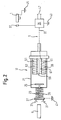
- FIG. 2 the magnetic insert 17 of the solenoid valve is shown in an enlarged view.
- the valve stem 23, as shown in FIG. 1, is shown in its closed position.
- the control device 35 is connected via the signal line 33 in series with the first solenoid valve coils 55 and the second solenoid coil 57.
- a connection end 59 of the solenoid coil 57 is arranged between the two counter-anchors 51.
- the terminal end 59 extends in an intermediate space 61 between the two counter-anchors 51 in the direction of the armature 25 of the valve stem 23.
- the armature 25 of the valve stem 23 serves as an electrical switch which closes a signal circuit S in contact with the terminal end 59.
- the electrical control device 35 In the signal circuit S are in series, the electrical control device 35, the first and second solenoid coil 55, 57, the connection end 59th of the valve stem 25 with its armature 25 is connected.
- the valve stem 23 is in electrical connection with the control device 35, which is also earthed via the second grounding connection 43, via the first earth connection 41 of the gas tap.
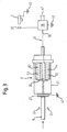
- the cock axis 9 pushes the valve plate 27 out of engagement with the valve seat 31 due to a pressure actuation of the toggle 11.
- the gas path 15 in the gas cock 7 is opened.
- the armature 25 is in electrical contact with the terminal end 59.
- the signal circuit S described above is therefore closed.
- a small amount of current, for example 20 mA from the control device 35 via the solenoid valve coils 55, 57, the terminal end 59, the valve stem 23, the first ground terminal 41 to the second ground terminal 43 again flow back into the control device 35.
- the control device 35 thus detects the opening of the gas path 15 through the valve stem 23.
- the control device 35 controls the spark plug 37 for flame ignition on the gas burner 1 at.
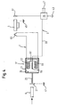
- the second embodiment of the invention is shown. Consequently, the electrical control device via the signal line 33 directly to the terminal end 59 in electrical connection.
- the two solenoid valve coils 55, 57 are not interposed in the signal circuit S.
- the electrical control device 35, the connection end 59 is the valve stem 23 to the armature 25 and its associated first ground terminal 41 and the second ground terminal 43 of the control device 35 connected in series.
- the gas burner 1 is assigned a thermocouple 63 for flame detection.
- the thermocouple 63 is connected in a thermal power circuit T, in series with the first solenoid valve coil and the second solenoid valve coil.
- thermocouple 63 In burner operation, the thermocouple 63 is heated by the flames and thereby generates a thermal current. By the thermal current of the thermal circuit T, a magnetic holding force is generated in the solenoid valve coils 55, 57, which holds the armature 25 of the valve stem 23 in its open position.
- the ignition electrode 37 is formed such that it can monitor extinction of the gas flame at the burner. In the case of extinction of the gas flame at the burner 1, a corresponding drop in temperature at the ignition electrode 37 is detected forwarded to the control device. In response to the detected signal, the electronic controller drives the ignition electrode 37 to cause re-ignition of the flame. Should this not occur within a predetermined time interval or after a number of predetermined sparks against ignition of the gas, the electrical control device interrupts the signal circuit. Characterized the magnetic holding force of the solenoid coils 55, 57 is interrupted, whereby the valve stem is returned to its closed position.
Landscapes
- Engineering & Computer Science (AREA)
- Chemical & Material Sciences (AREA)
- Combustion & Propulsion (AREA)
- Mechanical Engineering (AREA)
- General Engineering & Computer Science (AREA)
- Feeding And Controlling Fuel (AREA)
- Magnetically Actuated Valves (AREA)
Abstract
Description
- Die Erfindung betrifft ein Gaskochfeld mit zumindest einem Gashahn für einen Gasbrenner dem ein Elektromagnetventil zum Öffnen oder Schließen eines Gaswegs zu dem Gasbrenner zugeordnet ist, und einem Positionssensor, der eine Öffnungsstellung des Elektromagnetventils erfasst und ein entsprechendes Öffnungssignal an eine Steuereinrichtung leitet.
- Aus DE 198 25 846 A1 ist eine gattungsgemäße Vorrichtung zum Sichern einer Gasbrennstelle bekannt. Die Vorrichtung weis einen in einem Gashahn angeordneten Elektromagneten (Magneteinsatz) auf. Dessen notwendiger Haltestrom zur Öffnung des Elektromagnetventils während einer Gasverbrennung wird durch eine elektronische Steuereinrichtung auf den Elektromagneten übertragen. Der Steuereinrichtung ist ein Mikroschalter bzw. ein Positionssensor zugeordnet, der eine Druckbetätigung einer Hahnachse des Gashahnes erfasst. Wird zu Beginn eines Gaskochfeldbetriebes die Hahnachse einmalig gedrückt, so wird die Druckbetätigung der Hahnachse durch den Mikroschalter erfasst, der ein Öffnungssignal zu der Steuerungseinrichtung leitet. Mittels der eingedrückten Hahnachse wird ein Ventilstössel des Magneteinsatzes in seine Öffnungsstellung gebracht. Die Steuerungseinrichtung versorgt in Antwort auf das Öffnungssignal des Positionssensors den Magneteinsatz mit einem Haltestrom und steuert eine Zündelektrode zur Flammenentzündung am Gasbrenner entsprechend an.
- Die Aufgabe der vorliegenden Erfindung besteht darin, ein Gaskochfeld, einen Gashahn oder ein Elektromagnetventil für einen Gashahn bereitzustellen, bei dem dauerhaft ein zuverlässiger Betrieb ermöglicht ist.
- Die Aufgabe der Erfindung ist durch ein Gaskochfeld mit den Merkmalen des Patentanspruches 1 gelöst. Gemäß dem kennzeichnenden Teil des Patentanspruches 1 ist der Positionssensor innerhalb eines Gehäuses des Elektromagnetventils ausgebildet. Der Positionsschalter ist somit gegenüber äußeren Einflüssen weitgehend geschützt. Im Gegensatz dazu erfassen die Positionssensoren gemäß dem Stand der Technik nicht die Öffnungsstellung des Elektromagnetventils. Vielmehr wird gemäß dem Stand der Technik eine Betätigung der Hahnachse des Gashahns, beispielsweise eine Druckbetätigung erfasst. Die aus dem Stand der Technik bekannten Positionssensoren sind im Bereich einer Bedienblende an einer Außenseite des Gashahnes gehaltert und somit sehr störungsanfällig.
- Besonders vorteilhaft ist es, wenn das Elektromagnetventil im Sinne einer Bauteilreduzierung innerhalb des Gashahnes ausgebildet ist. In diesem Fall kann das Elektromagnetventil mittels einer Hahnachse in eine Öffnungsstellung gebracht werden, in der ein Gasweg zu dem Gasbrenner geöffnet ist.
- Vorteilhaft kann der Steuereinrichtung eine Zündelektrode zur Flammenentzündung am Gasbrenner zugeordnet sein. In diesem Fall kann die Steuereinrichtung in Antwort auf ein Öffnungssignal des Positionssensors die Zündelektrode zur Flammenentzündung ansteuern.
- Im Falle, dass das Elektromagnetventil im Gashahn ausgebildet ist, kann das Elektromagnetventil einen sogenannten Magneteinsatz aufweisen, der in den Gashahn montierbar ist. Der Magneteinsatz weist ein Gehäuse auf, in dem ein Ventilstössel verschiebbar geführt ist. Der Ventilstössel kann mittels einer elektromagnetisch erzeugten Haltekraft in seiner Öffnungsposition gehalten werden.
- Gemäß einem Ausführungsbeispiel kann der Positionssensor als ein elektrischer Schalter zum Schließen einer zu der Steuereinrichtung führenden Signalleitung ausgebildet sein. Der elektrische Schalter kann durch Betätigung des Elektromagnetventils in seine Schließstellung gebracht werden. In der Schließstellung ist die zu der Steuereinrichtung führende Signalleitung geschlossen, so dass die Steuereinrichtung einen Signalstrom erfassen kann.
- Gemäß einer Ausführungsform kann der elektrische Schalter durch den Ventilstössel des Elektromagnetventils ausgebildet sein. Der Ventilstössel des Elektromagnetventils kann in seiner Öffnungsposition sich mit einem Anschlussende der Signalleitung in Kontakt befinden. In diesem Zustand schließt der Ventilstössel die Signalleitung, so dass ein Signalstrom zu der elektrischen Steuereinrichtung fließen kann.
- Bevorzugt kann das innerhalb des Elektromagnetventils-Gehäuses ausgebildete Anschlussende des elektrischen Schalters zwischen zwei Gegenankern von Elektromagnetventilspulen angeordnet sein. Auf diese Weise ist das Anschlussende des elektrischen Schalters sicher gegen äußere Einflüsse, beispielsweise Stöße, geschützt.
- Der elektrische Schalter kann durch eine Druckbetätigung einen Signalstromkreis der Steuereinrichtung schließen. In dem Signalstromkreis kann ein Signalstrom von der elektrischen Steuereinrichtung zu dem Anschlussende des elektrischen Schalters zu dem Ventilstössel des Elektromagnetventils über einen ersten Erdungsanschluss des Ventilstössels zu einem zweiten Erdungsanschluss der Steuereinrichtung wieder zurück zu der Steuereinrichtung fließen.
- Zusätzlich kann in dem Signalstromkreis die zumindest eine Elektromagnetventilspule integriert sein. In diesem Fall kann bei geschlossenem elektrischem Schalter die zumindest eine Elektromagnetspule eine magnetische Haltekraft auf den Ventilstössel ausüben. Der Ventilstössel ist somit durch die magnetische Haltekraft in seiner Öffnungsposition gehalten.
- Nachfolgend sind zwei Ausführungsbeispiele der Erfindung anhand der beigefügten Figuren beschrieben:
- Figur 1 eine schematische Darstellung eines Gaskochfelds mit einem Gasbrenner sowie einem zugeordneten Gashahn;
- Figur 2 in einer vergrößerten Ansicht einen Magneteinsatz des Elektromagnetventils mit zugeordneter Steuereinrichtung sowie Gasbrenner;
- Figur 3 entsprechend der Figur 2 den Magneteinsatz mit seinem Ventilstössel in einer Öffnungsposition; und
- Figur 4 gemäß dem zweiten Ausführungsbeispiel einen Magneteinsatz mit zugeordnetem Brenner sowie zugeordneter Steuereinrichtung.
- In der Figur 1 ist gemäß dem ersten Ausführungsbeispiel in einer schematischen Darstellung ein Gaskochfeld mit einem Gasbrenner 1 gezeigt. In einer Gasleitung 3 zu dem Gasbrenner 1 ist ein Gashahn 7 zur Gasmengenregelung angeordnet. Der Gashahn 7 weist eine Hahnachse 9 auf, die über einen Betätigungsknebel 11 betätigt werden kann. Weiterhin ist in dem Gashahn ein elektromagnetisches Sicherheitsventil 13 integriert, das in seinem stromlosen Zustand einen Gasweg 15 innerhalb des Gashahnes unterbricht.
- Das Elektromagnetventil 13 weist einen Magneteinsatz 17 auf, der in eine entsprechende Aufnahmeöffnung 19 des Gashahnes eingesetzt ist. In einem Gehäuse 21 des Magneteinsatzes 17 ist ein Ventilstössel 23 mit seinem Magnetanker 25 verschiebbar geführt. An seinem äußeren Ende weist der Ventilstössel 23 einen Ventilteller 27 auf. In der Figur 1 ist der Ventilteller 27 mittels einer Rückstellfeder 29 in Anlage mit einem Ventilsitz 31 gedrückt. Dadurch ist der Gasweg 15 innerhalb des Gashahnes 7 unterbrochen.
- Der Magneteinsatz 17 des Elektromagnetventils 13 ist über eine erste Signalleitung 33 mit einer elektrischen Steuereinrichtung 35 in Verbindung. Die elektrische Steuereinrichtung 35 ist mit einer Zündelektrode 37 zur Flammenentzündung an dem Gasbrenner 1 in Verbindung.
- In der Figur 1 ist der Ventilstössel 23 über einen ersten Erdungsanschluss 41 elektrisch geerdet. Die Steuereinrichtung 35 ist über einen zweiten Erdungsanschluss 43 elektrisch geerdet, während der Gasbrenner über einen dritten Erdungsanschluss 45 geerdet ist. Die Steuereinrichtung 35 wird über Netzanschlüsse 47 mit Spannung versorgt.
- Zur Inbetriebnahme des Gasbrenners 1 ist der Drehknebel 11 des Gashahnes 7 in Pfeilrichtung I zu drücken. Durch die Druckbetätigung verschiebt die Hahnachse 9 den Ventilstössel 23 des Magneteinsatzes 17 in eine Öffnungsstellung. In der Öffnungsstellung des Ventilstössels 23 ist der durch den Gashahn 7 führende Gasweg 15 geöffnet. Gleichzeitig ist bei geöffnetem Ventilstössel 23 der Magnetanker 25 des Ventilstössels 23 in Kontakt mit den beiden Gegenankern 51 für die Elektromagnet-Spulen 53. Die Gegenanker 51 sind innerhalb des Magneteinsatz-Gehäuses 21 angeordnet.
- In den Figuren 2 und 3 ist der Magneteinsatz 17 des Elektromagnetventils in vergrößerter Ansicht dargestellt. In der Figur 2 ist der Ventilstössel 23, wie in der Figur 1, in seiner Schließstellung gezeigt. Die Steuereinrichtung 35 ist über die Signalleitung 33 in Reihe mit der ersten Elektromagnetventilspulen 55 sowie der zweiten Elektromagnet-Spule 57 geschaltet. Ein Anschlussende 59 der Elektromagnet-Spule 57 ist dabei zwischen den beiden Gegenankern 51 angeordnet. Das Anschlussende 59 erstreckt sich dabei in einem Zwischenraum 61 zwischen den beiden Gegenankern 51 in Richtung auf den Magnetanker 25 des Ventilstössels 23. Dabei dient der Magnetanker 25 des Ventilstössels 23 als ein elektrischer Schalter, der bei Kontakt mit dem Anschlussende 59 einen Signalschaltkreis S schließt. In dem Signalschaltkreis S sind in Reihe die elektrischen Steuereinrichtung 35, die erste und zweite Elektromagnet-Spule 55, 57, das Anschlussende 59. der Ventilstössel 25 mit seinem Magnetanker 25 geschaltet. Der Ventilstössel 23 ist über den ersten Erdungsanschluss 41 des Gashahns in elektrischer Verbindung mit der ebenfalls über den zweiten Erdungsanschluss 43 geerdeten Steuereinrichtung 35.
- In der Figur 3 drückt die Hahnachse 9 aufgrund einer Druckbetätigung des Knebels 11 den Ventilteller 27 außer Anlage mit dem Ventilsitz 31. Dadurch ist einerseits der Gasweg 15 im Gashahn 7 geöffnet. Andererseits ist der Magnetanker 25 im elektrischen Kontakt mit den Anschlussende 59. Der oben beschriebene Signalschaltkreis S ist daher geschlossen. In diesem Fall kann eine geringfügige Strommenge, beispielsweise 20 mA, von der Steuereinrichtung 35 über die Elektromagnetventilspulen 55, 57, dem Anschlussende 59, dem Ventilstössel 23, dem ersten Erdungsanschluss 41 zum zweiten Erdungsanschluss 43 wieder zurück in die Steuereinrichtung 35 fließen. Die Steuereinrichtung 35 erfasst somit die Öffnung des Gasweges 15 durch den Ventilstössel 23. In Antwort auf dieses Öffnungssignal steuert die Steuereinrichtung 35 die Zündkerze 37 zur Flammenentzündung am Gasbrenner 1 an.
- In der Figur 3 ist das zweite Ausführungsbeispiel der Erfindung dargestellt. Demzufolge ist die elektrische Steuereinrichtung über die Signalleitung 33 unmittelbar mit dem Anschlussende 59 in elektrischer Verbindung. Im Unterschied zu dem ersten Ausführungsbeispiel sind daher die beiden Elektromagnetventilspulen 55, 57 nicht in den Signalschaltkreis S zwischengeschaltet. In dem Signalschaltkreis S gemäß der Figur 3 ist daher die elektrische Steuereinrichtung 35, das Anschlussende 59, der Ventilstössel 23 mit dem Magnetanker 25 sowie dessen zugeordneter erster Erdungsanschluss 41 und der zweite Erdungsanschluss 43 der Steuereinrichtung 35 in Reihe geschaltet. Im Unterschied zu dem ersten Ausführungsbeispiel ist dem Gasbrenner 1 ein Thermoelement 63 für eine Flammenerkennung zugeordnet. Das Thermoelement 63 ist in einem Thermo-Stromschaltkreis T geschaltet, und zwar in Reihe mit der ersten Elektromagnetventilspule und der zweiten Elektromagnetventilspule. Im Brennerbetrieb wird das Thermoelement 63 durch die Flammen erwärmt und erzeugt dadurch einen Thermostrom. Durch den Thermostrom des Thermoschaltkreises T wird in den Elektromagnetventilspulen 55, 57 eine magnetische Haltekraft erzeugt, die den Magnetanker 25 des Ventilstössels 23 in seiner Öffnungsposition hält.
- Im Unterschied zum zweiten Ausführungsbeispiel ist gemäß dem ersten Ausführungsbeispiel die Zündelektrode 37 derart ausgebildet, dass sie ein Erlöschen der Gasflamme am Brenner überwachen kann. Im Falle eines Erlöschens der Gasflamme am Brenner 1 wird ein entsprechender Temperaturabfall an der Zündelektrode 37 erfasst zu der Steuereinrichtung weitergeleitet. In Antwort auf das erfasste Signal steuert die elektronische Steuereinrichtung die Zündelektrode 37 an, um eine erneute Flammenentzündung zu bewirken. Sollte diese wider Zündung des Gases innerhalb eines vorgegebenen Zeitintervalls oder nach einer Anzahl von vorgegebenen Zündfunken nicht erfolgen, unterbricht die elektrische Steuereinrichtung den Signalschaltkreis. Dadurch wird die magnetische Haltekraft der Elektromagnet-Spulen 55, 57 unterbrochen, wodurch sich der Ventilstössel in seine Schließposition zurückstellt.
Claims (17)
- Gaskochfeld mit zumindest einem Gashahn (7) für einen Gasbrenner (1) dem ein Elektromagnetventil (13) zum Öffnen oder Schließen eines Gasweges (15) zu dem Gasbrenner (1) zugeordnet ist, und einem Positionssensor (23, 59), der eine Öffnungsstellung des Elektromagnetventils (13) erfasst und ein entsprechendes Öffnungssignal an eine Steuereinrichtung (35) leitet, dadurch gekennzeichnet, dass der Positionssensor (23, 59) innerhalb eines Gehäuses (21) des Elektromagnetventils (13) ausgebildet ist.
- Gaskochfeld nach Anspruch 1, dadurch gekennzeichnet, dass das Elektromagnetventil (13) im Gashahn (7) ausgebildet ist.
- Gaskochfeld nach einem der Ansprüche 1 oder 2, dadurch gekennzeichnet, dass der Gashahn (7) eine Hahnachse (9) aufweist, die bei einer Druckbetätigung (I) das Elektromagnetventil (13) in eine Öffnungsstellung bringt.
- Gaskochfeld nach einem der vorhergehenden Ansprüche, dadurch gekennzeichnet, dass der Steuereinrichtung (35) eine Zündelektrode (37) ausgebildet ist.
- Gaskochfeld nach einem der vorhergehenden Ansprüche, dadurch gekennzeichnet, dass die Steuereinrichtung (35) in Antwort auf das Öffnungssignal des Positionssensors (23, 59) die Zündelektrode (37) für eine Flammenentzündung ansteuert.
- Gaskochfeld nach einem der vorhergehenden Ansprüche, dadurch gekennzeichnet, dass der Positionssensor (23, 59) als ein elektrischer Schalter zum Schließen einer zu der Steuereinrichtung (35) führenden Signalleitung (33) ausgebildet ist.
- Gaskochfeld nach Anspruch 6, dadurch gekennzeichnet, dass der elektrische Schalter (23, 59) als ein Ventilstössel (23) des Elektromagnetventils (13) ausgebildet ist, der bei einer Druckbetätigung (I) des Gashahns (7) in Kontakt mit einem Anschlussende (59) der Signalleitung (33) kommt.
- Gaskochfeld nach Anspruch 7, dadurch gekennzeichnet, dass das Anschlussende (59) des elektrischen Schalters (23, 59) zwischen zwei Gegenankern (51) von Elektromagnetventilspulen (55, 57) angeordnet ist.
- Gaskochfeld nach einem der Ansprüche 7 oder 8, dadurch gekennzeichnet, dass der elektrische Schalter (23, 59) bei einer Druckbetätigung (I) einen Signalschaltkreis (S) der Steuereinrichtung (35) schließt.
- Gaskochfeld nach Anspruch 9, dadurch gekennzeichnet, dass in dem Signalschaltkreis (S) die Steuereinrichtung (35), das Anschlußende (59), der Ventilstössel (23) mit seinen Magnetanker (25) in Reihe angeordnet ist, der elektrisch mit der Steuereinrichtung (35) verbunden ist.
- Gaskochfeld nach Anspruch 10, dadurch gekennzeichnet, dass die elektrische Verbindung zwischen dem Ventilstössel (23) und der Steuereinrichtung über einen ersten Erdungsanschluss (41) des Gashahns (7) und einen zweiten Erdungsanschluss (43) der Steuereinrichtung (35) ausgebildet.
- Gaskochfeld nach einem der Ansprüche 7 bis 11, dadurch gekennzeichnet, dass der Ventilstössel (23) mittels des Gashahns (7) über einen ersten Erdungsanschluss (41) elektrisch geerdet ist.
- Gaskochfeld nach einem der Ansprüche 10, 11 oder 12, dadurch gekennzeichnet, dass in dem Signalschaltkreis (S) zusätzlich Elektromagnetventilspulen (55, 57) integriert sind.
- Gaskochfeld nach einem der vorhergehenden Ansprüche, dadurch gekennzeichnet, dass die Steuereinrichtung (35) und der Gashahn (7) über Erdungsanschlüsse (41, 43) elektrisch geerdet ist.
- Gaskochfeld nach einem der Ansprüche 7 bis 14, dadurch gekennzeichnet, dass bei geschlossenem elektrischen Schalter (23, 59) die Elektromagnetspulen (55, 57) den Ventilstössel (23) magnetisch in seiner Öffnungsposition halten.
- Gashahn für ein Gaskochfeld gemäß einem der vorhergehenden Ansprüche.
- Elektromagnetventil für einen Gashahn gemäß dem Anspruch 16.
Applications Claiming Priority (1)
| Application Number | Priority Date | Filing Date | Title |
|---|---|---|---|
| ES200402784A ES2258910B1 (es) | 2004-11-10 | 2004-11-10 | Placa de cocina de gas. |
Publications (3)
| Publication Number | Publication Date |
|---|---|
| EP1657492A2 true EP1657492A2 (de) | 2006-05-17 |
| EP1657492A3 EP1657492A3 (de) | 2007-12-26 |
| EP1657492B1 EP1657492B1 (de) | 2013-02-13 |
Family
ID=35735179
Family Applications (1)
| Application Number | Title | Priority Date | Filing Date |
|---|---|---|---|
| EP05110103A Expired - Lifetime EP1657492B1 (de) | 2004-11-10 | 2005-10-28 | Gaskochfeld mit einem Gashahn |
Country Status (2)
| Country | Link |
|---|---|
| EP (1) | EP1657492B1 (de) |
| ES (2) | ES2258910B1 (de) |
Cited By (2)
| Publication number | Priority date | Publication date | Assignee | Title |
|---|---|---|---|---|
| CN104776460A (zh) * | 2015-04-21 | 2015-07-15 | 赵振华 | 一种用于燃气灶具的输气装置与燃气灶具装置 |
| EP3205935A1 (de) | 2016-02-11 | 2017-08-16 | Copreci, S.Coop. | Gashahn |
Families Citing this family (4)
| Publication number | Priority date | Publication date | Assignee | Title |
|---|---|---|---|---|
| ES2391516B1 (es) * | 2005-02-28 | 2013-10-04 | Bsh Electrodomésticos España, S.A. | Aparato de gas, en particular un fuego de una cocina de gas. |
| ES2291083B1 (es) * | 2005-08-05 | 2008-10-16 | Bsh Electrodomesticos España, S.A. | Placa de cocina de gas. |
| ES2291084B1 (es) * | 2005-08-05 | 2008-10-16 | Bsh Electrodomesticos España, S.A. | Placa de cocina de gas. |
| ES2902994T3 (es) | 2016-07-11 | 2022-03-30 | Copreci S Coop | Aparato de cocción a gas |
Citations (3)
| Publication number | Priority date | Publication date | Assignee | Title |
|---|---|---|---|---|
| US3157222A (en) | 1961-04-08 | 1964-11-17 | Kromschroeder Ag G | Thermoelectrically operated semi-automatic flame control device for two or more burners |
| EP0581391A1 (de) | 1992-07-31 | 1994-02-02 | Deltec Fuel Systems B.V. | Steuerungssystem zum Zuführen eines Gasstromes zu einem Gasverbrauchsapparat |
| DE19825846A1 (de) | 1998-06-10 | 1999-12-16 | Agt Gas Technology Gmbh | Vorrichtung zum Sichern einer Gasbrennstelle |
Family Cites Families (8)
| Publication number | Priority date | Publication date | Assignee | Title |
|---|---|---|---|---|
| DE1240008B (de) * | 1963-05-04 | 1967-05-11 | Junkers & Co | Gashahn |
| FR1580257A (de) * | 1968-06-06 | 1969-09-05 | ||
| US4147494A (en) * | 1976-04-14 | 1979-04-03 | Howa Sangyo Kabushiki Kaisha | Gas burner ignition device |
| GB2109603B (en) * | 1981-10-09 | 1986-02-12 | Thorn Emi Gas Appliances Limit | A cooking control and cooking apparatus including such a control |
| FR2758179A1 (fr) * | 1997-01-07 | 1998-07-10 | Eaton Sa Monaco | Dispositif de surveillance et de securite pour appareil de cuisson ou de chauffage a gaz |
| FR2761459B1 (fr) * | 1997-03-28 | 1999-06-18 | Gaz De France | Systeme de securite pour bruleurs d'appareil de cuisson |
| US6666676B2 (en) * | 2000-08-17 | 2003-12-23 | Comercial Acros Whirlpool S.A. De C.V. | Programmable burner for gas stoves |
| US20020073985A1 (en) * | 2000-12-18 | 2002-06-20 | Bsh Home Appliances Corporation | Pulsed sequence burner control with valve |
-
2004
- 2004-11-10 ES ES200402784A patent/ES2258910B1/es not_active Expired - Fee Related
-
2005
- 2005-10-28 ES ES05110103T patent/ES2400718T3/es not_active Expired - Lifetime
- 2005-10-28 EP EP05110103A patent/EP1657492B1/de not_active Expired - Lifetime
Patent Citations (3)
| Publication number | Priority date | Publication date | Assignee | Title |
|---|---|---|---|---|
| US3157222A (en) | 1961-04-08 | 1964-11-17 | Kromschroeder Ag G | Thermoelectrically operated semi-automatic flame control device for two or more burners |
| EP0581391A1 (de) | 1992-07-31 | 1994-02-02 | Deltec Fuel Systems B.V. | Steuerungssystem zum Zuführen eines Gasstromes zu einem Gasverbrauchsapparat |
| DE19825846A1 (de) | 1998-06-10 | 1999-12-16 | Agt Gas Technology Gmbh | Vorrichtung zum Sichern einer Gasbrennstelle |
Cited By (6)
| Publication number | Priority date | Publication date | Assignee | Title |
|---|---|---|---|---|
| CN104776460A (zh) * | 2015-04-21 | 2015-07-15 | 赵振华 | 一种用于燃气灶具的输气装置与燃气灶具装置 |
| EP3205935A1 (de) | 2016-02-11 | 2017-08-16 | Copreci, S.Coop. | Gashahn |
| US20170234448A1 (en) * | 2016-02-11 | 2017-08-17 | Coprecitec, S.L. | Gas Cock |
| CN107062300A (zh) * | 2016-02-11 | 2017-08-18 | 科普莱赛泰克公司 | 气体旋塞 |
| US9976670B2 (en) * | 2016-02-11 | 2018-05-22 | Copreci, S. Coop. | Gas cock |
| CN107062300B (zh) * | 2016-02-11 | 2019-12-10 | 科普莱赛泰克公司 | 气体旋塞 |
Also Published As
| Publication number | Publication date |
|---|---|
| ES2400718T3 (es) | 2013-04-11 |
| EP1657492A3 (de) | 2007-12-26 |
| EP1657492B1 (de) | 2013-02-13 |
| ES2258910B1 (es) | 2007-06-01 |
| ES2258910A1 (es) | 2006-09-01 |
Similar Documents
| Publication | Publication Date | Title |
|---|---|---|
| EP0964326B1 (de) | Vorrichtung zum Sichern einer Gasbrennstelle | |
| EP2850629B1 (de) | Elektrischer schalter | |
| EP1657492B1 (de) | Gaskochfeld mit einem Gashahn | |
| EP1657491B1 (de) | Gaskochfeld | |
| DE19752472A1 (de) | Anordnung und Verfahren zum Steuern einer Heizvorrichtung für Gaskochmulden | |
| DE69400840T2 (de) | Brennersteuereinrichtung | |
| DE10309469B3 (de) | Gasregelarmatur | |
| EP1856451B1 (de) | Gasgerät, insbesondere gaskochfeld | |
| EP1750059A2 (de) | Gaskochfeld | |
| DE2754496C2 (de) | Gasventil mit Sicherheitszündung | |
| WO2009037132A1 (de) | Gaskochvorrichtungsanordnung | |
| EP1552199B1 (de) | Gashahn mit einem elektromagnetischen sicherheitsventil | |
| DE10217008B4 (de) | Verfahren für den Betrieb eines gasbetriebenen Koch-oder Bratgeräts und Vorrichtung zur Durchführung des Verfahrens | |
| EP3164642A1 (de) | Gasbrenneranordnung, kochstelle und herd | |
| DE3022635C2 (de) | Steuerschaltung für eine Feuerungsanlage | |
| DE19723653B4 (de) | Sicherheitsabschaltvorrichtung für Gasverbrennungsgeräte | |
| EP1467150B1 (de) | Zündsicherung | |
| EP1457724B1 (de) | Ventil mit Motorantrieb | |
| DE60216763T2 (de) | Sicherheitseinrichtung für eine feurerungsanlage mit einer verzögerungszeit durch eine elektronische schaltung | |
| DE2640931C3 (de) | Steuer- und Überwachungseinrichtung für öl- oder Gasbrenner | |
| DE3841084A1 (de) | Feuerungsautomat | |
| DE3717449C1 (en) | Field cooking stove with a drawer containing a burner | |
| DE19752323C1 (de) | Wechselstromgespeiste Steuerschaltung für Gasmagnetventile | |
| EP3102880B1 (de) | Gasbrenneranordnung, kochstelle und herd | |
| DE19606255A1 (de) | Feuerungsautomat |
Legal Events
| Date | Code | Title | Description |
|---|---|---|---|
| PUAI | Public reference made under article 153(3) epc to a published international application that has entered the european phase |
Free format text: ORIGINAL CODE: 0009012 |
|
| AK | Designated contracting states |
Kind code of ref document: A2 Designated state(s): AT BE BG CH CY CZ DE DK EE ES FI FR GB GR HU IE IS IT LI LT LU LV MC NL PL PT RO SE SI SK TR |
|
| AX | Request for extension of the european patent |
Extension state: AL BA HR MK YU |
|
| RIN1 | Information on inventor provided before grant (corrected) |
Inventor name: NABARRETTI, ROGERIO Inventor name: HERRERA ESTRADA, PEDRO Inventor name: RUBIO ABAD, JULIO Inventor name: PLACER MARURI, EMILIO Inventor name: PALACIOS VALDUEZA, LUIS ANTONIO Inventor name: LEON GARCIA, JOSE |
|
| PUAL | Search report despatched |
Free format text: ORIGINAL CODE: 0009013 |
|
| AK | Designated contracting states |
Kind code of ref document: A3 Designated state(s): AT BE BG CH CY CZ DE DK EE ES FI FR GB GR HU IE IS IT LI LT LU LV MC NL PL PT RO SE SI SK TR |
|
| AX | Request for extension of the european patent |
Extension state: AL BA HR MK YU |
|
| 17P | Request for examination filed |
Effective date: 20080626 |
|
| AKX | Designation fees paid |
Designated state(s): AT BE BG CH CY CZ DE DK EE ES FI FR GB GR HU IE IS IT LI LT LU LV MC NL PL PT RO SE SI SK TR |
|
| 17Q | First examination report despatched |
Effective date: 20080814 |
|
| GRAP | Despatch of communication of intention to grant a patent |
Free format text: ORIGINAL CODE: EPIDOSNIGR1 |
|
| GRAS | Grant fee paid |
Free format text: ORIGINAL CODE: EPIDOSNIGR3 |
|
| GRAA | (expected) grant |
Free format text: ORIGINAL CODE: 0009210 |
|
| AK | Designated contracting states |
Kind code of ref document: B1 Designated state(s): AT BE BG CH CY CZ DE DK EE ES FI FR GB GR HU IE IS IT LI LT LU LV MC NL PL PT RO SE SI SK TR |
|
| REG | Reference to a national code |
Ref country code: GB Ref legal event code: FG4D Free format text: NOT ENGLISH |
|
| REG | Reference to a national code |
Ref country code: AT Ref legal event code: REF Ref document number: 596702 Country of ref document: AT Kind code of ref document: T Effective date: 20130215 |
|
| REG | Reference to a national code |
Ref country code: IE Ref legal event code: FG4D Free format text: LANGUAGE OF EP DOCUMENT: GERMAN |
|
| REG | Reference to a national code |
Ref country code: ES Ref legal event code: FG2A Ref document number: 2400718 Country of ref document: ES Kind code of ref document: T3 Effective date: 20130411 Ref country code: DE Ref legal event code: R096 Ref document number: 502005013464 Country of ref document: DE Effective date: 20130411 |
|
| REG | Reference to a national code |
Ref country code: NL Ref legal event code: T3 |
|
| REG | Reference to a national code |
Ref country code: LT Ref legal event code: MG4D |
|
| PG25 | Lapsed in a contracting state [announced via postgrant information from national office to epo] |
Ref country code: SE Free format text: LAPSE BECAUSE OF FAILURE TO SUBMIT A TRANSLATION OF THE DESCRIPTION OR TO PAY THE FEE WITHIN THE PRESCRIBED TIME-LIMIT Effective date: 20130213 Ref country code: BG Free format text: LAPSE BECAUSE OF FAILURE TO SUBMIT A TRANSLATION OF THE DESCRIPTION OR TO PAY THE FEE WITHIN THE PRESCRIBED TIME-LIMIT Effective date: 20130513 Ref country code: IS Free format text: LAPSE BECAUSE OF FAILURE TO SUBMIT A TRANSLATION OF THE DESCRIPTION OR TO PAY THE FEE WITHIN THE PRESCRIBED TIME-LIMIT Effective date: 20130613 Ref country code: LT Free format text: LAPSE BECAUSE OF FAILURE TO SUBMIT A TRANSLATION OF THE DESCRIPTION OR TO PAY THE FEE WITHIN THE PRESCRIBED TIME-LIMIT Effective date: 20130213 Ref country code: CY Free format text: LAPSE BECAUSE OF FAILURE TO SUBMIT A TRANSLATION OF THE DESCRIPTION OR TO PAY THE FEE WITHIN THE PRESCRIBED TIME-LIMIT Effective date: 20130213 |
|
| PG25 | Lapsed in a contracting state [announced via postgrant information from national office to epo] |
Ref country code: LV Free format text: LAPSE BECAUSE OF FAILURE TO SUBMIT A TRANSLATION OF THE DESCRIPTION OR TO PAY THE FEE WITHIN THE PRESCRIBED TIME-LIMIT Effective date: 20130213 Ref country code: FI Free format text: LAPSE BECAUSE OF FAILURE TO SUBMIT A TRANSLATION OF THE DESCRIPTION OR TO PAY THE FEE WITHIN THE PRESCRIBED TIME-LIMIT Effective date: 20130213 Ref country code: PL Free format text: LAPSE BECAUSE OF FAILURE TO SUBMIT A TRANSLATION OF THE DESCRIPTION OR TO PAY THE FEE WITHIN THE PRESCRIBED TIME-LIMIT Effective date: 20130213 Ref country code: PT Free format text: LAPSE BECAUSE OF FAILURE TO SUBMIT A TRANSLATION OF THE DESCRIPTION OR TO PAY THE FEE WITHIN THE PRESCRIBED TIME-LIMIT Effective date: 20130613 Ref country code: SI Free format text: LAPSE BECAUSE OF FAILURE TO SUBMIT A TRANSLATION OF THE DESCRIPTION OR TO PAY THE FEE WITHIN THE PRESCRIBED TIME-LIMIT Effective date: 20130213 |
|
| PG25 | Lapsed in a contracting state [announced via postgrant information from national office to epo] |
Ref country code: RO Free format text: LAPSE BECAUSE OF FAILURE TO SUBMIT A TRANSLATION OF THE DESCRIPTION OR TO PAY THE FEE WITHIN THE PRESCRIBED TIME-LIMIT Effective date: 20130213 Ref country code: SK Free format text: LAPSE BECAUSE OF FAILURE TO SUBMIT A TRANSLATION OF THE DESCRIPTION OR TO PAY THE FEE WITHIN THE PRESCRIBED TIME-LIMIT Effective date: 20130213 Ref country code: EE Free format text: LAPSE BECAUSE OF FAILURE TO SUBMIT A TRANSLATION OF THE DESCRIPTION OR TO PAY THE FEE WITHIN THE PRESCRIBED TIME-LIMIT Effective date: 20130213 Ref country code: CZ Free format text: LAPSE BECAUSE OF FAILURE TO SUBMIT A TRANSLATION OF THE DESCRIPTION OR TO PAY THE FEE WITHIN THE PRESCRIBED TIME-LIMIT Effective date: 20130213 Ref country code: DK Free format text: LAPSE BECAUSE OF FAILURE TO SUBMIT A TRANSLATION OF THE DESCRIPTION OR TO PAY THE FEE WITHIN THE PRESCRIBED TIME-LIMIT Effective date: 20130213 |
|
| PLBE | No opposition filed within time limit |
Free format text: ORIGINAL CODE: 0009261 |
|
| STAA | Information on the status of an ep patent application or granted ep patent |
Free format text: STATUS: NO OPPOSITION FILED WITHIN TIME LIMIT |
|
| 26N | No opposition filed |
Effective date: 20131114 |
|
| REG | Reference to a national code |
Ref country code: DE Ref legal event code: R097 Ref document number: 502005013464 Country of ref document: DE Effective date: 20131114 |
|
| BERE | Be: lapsed |
Owner name: BSH BOSCH UND SIEMENS HAUSGERATE G.M.B.H. Effective date: 20131031 |
|
| PG25 | Lapsed in a contracting state [announced via postgrant information from national office to epo] |
Ref country code: MC Free format text: LAPSE BECAUSE OF FAILURE TO SUBMIT A TRANSLATION OF THE DESCRIPTION OR TO PAY THE FEE WITHIN THE PRESCRIBED TIME-LIMIT Effective date: 20130213 |
|
| REG | Reference to a national code |
Ref country code: CH Ref legal event code: PL |
|
| REG | Reference to a national code |
Ref country code: IE Ref legal event code: MM4A |
|
| PG25 | Lapsed in a contracting state [announced via postgrant information from national office to epo] |
Ref country code: CH Free format text: LAPSE BECAUSE OF NON-PAYMENT OF DUE FEES Effective date: 20131031 Ref country code: LI Free format text: LAPSE BECAUSE OF NON-PAYMENT OF DUE FEES Effective date: 20131031 |
|
| PG25 | Lapsed in a contracting state [announced via postgrant information from national office to epo] |
Ref country code: BE Free format text: LAPSE BECAUSE OF NON-PAYMENT OF DUE FEES Effective date: 20131031 |
|
| PG25 | Lapsed in a contracting state [announced via postgrant information from national office to epo] |
Ref country code: IE Free format text: LAPSE BECAUSE OF NON-PAYMENT OF DUE FEES Effective date: 20131028 |
|
| REG | Reference to a national code |
Ref country code: AT Ref legal event code: MM01 Ref document number: 596702 Country of ref document: AT Kind code of ref document: T Effective date: 20131028 |
|
| PG25 | Lapsed in a contracting state [announced via postgrant information from national office to epo] |
Ref country code: AT Free format text: LAPSE BECAUSE OF NON-PAYMENT OF DUE FEES Effective date: 20131028 |
|
| REG | Reference to a national code |
Ref country code: DE Ref legal event code: R081 Ref document number: 502005013464 Country of ref document: DE Owner name: BSH HAUSGERAETE GMBH, DE Free format text: FORMER OWNER: BSH BOSCH UND SIEMENS HAUSGERAETE GMBH, 81739 MUENCHEN, DE Effective date: 20150407 Ref country code: DE Ref legal event code: R081 Ref document number: 502005013464 Country of ref document: DE Owner name: BSH HAUSGERAETE GMBH, DE Free format text: FORMER OWNER: BSH BOSCH UND SIEMENS HAUSGERAETE GMBH, 81739 MUENCHEN, DE Effective date: 20130213 |
|
| REG | Reference to a national code |
Ref country code: ES Ref legal event code: PC2A Owner name: BSH HAUSGERATE GMBH Effective date: 20150529 |
|
| PG25 | Lapsed in a contracting state [announced via postgrant information from national office to epo] |
Ref country code: LU Free format text: LAPSE BECAUSE OF NON-PAYMENT OF DUE FEES Effective date: 20131028 Ref country code: HU Free format text: LAPSE BECAUSE OF FAILURE TO SUBMIT A TRANSLATION OF THE DESCRIPTION OR TO PAY THE FEE WITHIN THE PRESCRIBED TIME-LIMIT; INVALID AB INITIO Effective date: 20051028 |
|
| PG25 | Lapsed in a contracting state [announced via postgrant information from national office to epo] |
Ref country code: GR Free format text: LAPSE BECAUSE OF NON-PAYMENT OF DUE FEES Effective date: 20130213 |
|
| REG | Reference to a national code |
Ref country code: FR Ref legal event code: PLFP Year of fee payment: 11 |
|
| REG | Reference to a national code |
Ref country code: FR Ref legal event code: CD Owner name: BSH HAUSGERATE GMBH Effective date: 20151022 |
|
| PGFP | Annual fee paid to national office [announced via postgrant information from national office to epo] |
Ref country code: TR Payment date: 20151016 Year of fee payment: 11 Ref country code: DE Payment date: 20151031 Year of fee payment: 11 Ref country code: GB Payment date: 20151026 Year of fee payment: 11 Ref country code: IT Payment date: 20151026 Year of fee payment: 11 |
|
| PGFP | Annual fee paid to national office [announced via postgrant information from national office to epo] |
Ref country code: ES Payment date: 20151023 Year of fee payment: 11 Ref country code: FR Payment date: 20151026 Year of fee payment: 11 Ref country code: NL Payment date: 20151026 Year of fee payment: 11 |
|
| REG | Reference to a national code |
Ref country code: DE Ref legal event code: R119 Ref document number: 502005013464 Country of ref document: DE |
|
| REG | Reference to a national code |
Ref country code: NL Ref legal event code: MM Effective date: 20161101 |
|
| GBPC | Gb: european patent ceased through non-payment of renewal fee |
Effective date: 20161028 |
|
| REG | Reference to a national code |
Ref country code: FR Ref legal event code: ST Effective date: 20170630 |
|
| PG25 | Lapsed in a contracting state [announced via postgrant information from national office to epo] |
Ref country code: GB Free format text: LAPSE BECAUSE OF NON-PAYMENT OF DUE FEES Effective date: 20161028 Ref country code: DE Free format text: LAPSE BECAUSE OF NON-PAYMENT OF DUE FEES Effective date: 20170503 Ref country code: FR Free format text: LAPSE BECAUSE OF NON-PAYMENT OF DUE FEES Effective date: 20161102 |
|
| PG25 | Lapsed in a contracting state [announced via postgrant information from national office to epo] |
Ref country code: NL Free format text: LAPSE BECAUSE OF NON-PAYMENT OF DUE FEES Effective date: 20161101 |
|
| PG25 | Lapsed in a contracting state [announced via postgrant information from national office to epo] |
Ref country code: IT Free format text: LAPSE BECAUSE OF NON-PAYMENT OF DUE FEES Effective date: 20161028 |
|
| PG25 | Lapsed in a contracting state [announced via postgrant information from national office to epo] |
Ref country code: ES Free format text: LAPSE BECAUSE OF NON-PAYMENT OF DUE FEES Effective date: 20161029 |
|
| REG | Reference to a national code |
Ref country code: ES Ref legal event code: FD2A Effective date: 20181123 |
|
| PG25 | Lapsed in a contracting state [announced via postgrant information from national office to epo] |
Ref country code: TR Free format text: LAPSE BECAUSE OF NON-PAYMENT OF DUE FEES Effective date: 20161028 |