EP1657065B1 - Tête d'impression, son procédé de fabrication et imprimante - Google Patents
Tête d'impression, son procédé de fabrication et imprimante Download PDFInfo
- Publication number
- EP1657065B1 EP1657065B1 EP06001852A EP06001852A EP1657065B1 EP 1657065 B1 EP1657065 B1 EP 1657065B1 EP 06001852 A EP06001852 A EP 06001852A EP 06001852 A EP06001852 A EP 06001852A EP 1657065 B1 EP1657065 B1 EP 1657065B1
- Authority
- EP
- European Patent Office
- Prior art keywords
- ink
- head
- nozzle
- print head
- formed member
- Prior art date
- Legal status (The legal status is an assumption and is not a legal conclusion. Google has not performed a legal analysis and makes no representation as to the accuracy of the status listed.)
- Expired - Lifetime
Links
- 238000004519 manufacturing process Methods 0.000 title description 22
- 239000000758 substrate Substances 0.000 claims description 142
- 239000000976 ink Substances 0.000 claims description 112
- 238000010438 heat treatment Methods 0.000 claims description 82
- 238000010030 laminating Methods 0.000 claims description 39
- PXHVJJICTQNCMI-UHFFFAOYSA-N Nickel Chemical compound [Ni] PXHVJJICTQNCMI-UHFFFAOYSA-N 0.000 claims description 35
- 239000000463 material Substances 0.000 claims description 24
- 229910052759 nickel Inorganic materials 0.000 claims description 17
- 239000003086 colorant Substances 0.000 claims description 12
- 239000004065 semiconductor Substances 0.000 description 23
- 238000006073 displacement reaction Methods 0.000 description 22
- 230000004888 barrier function Effects 0.000 description 19
- 238000003475 lamination Methods 0.000 description 19
- 238000000034 method Methods 0.000 description 19
- 239000002609 medium Substances 0.000 description 14
- XUIMIQQOPSSXEZ-UHFFFAOYSA-N Silicon Chemical compound [Si] XUIMIQQOPSSXEZ-UHFFFAOYSA-N 0.000 description 12
- 230000002093 peripheral effect Effects 0.000 description 12
- 229910052710 silicon Inorganic materials 0.000 description 12
- 239000010703 silicon Substances 0.000 description 12
- 229910045601 alloy Inorganic materials 0.000 description 8
- 239000000956 alloy Substances 0.000 description 8
- 230000015556 catabolic process Effects 0.000 description 8
- 238000006731 degradation reaction Methods 0.000 description 8
- 239000010408 film Substances 0.000 description 8
- 238000010276 construction Methods 0.000 description 7
- 229910001374 Invar Inorganic materials 0.000 description 6
- 239000000853 adhesive Substances 0.000 description 6
- 230000001070 adhesive effect Effects 0.000 description 6
- XEEYBQQBJWHFJM-UHFFFAOYSA-N Iron Chemical compound [Fe] XEEYBQQBJWHFJM-UHFFFAOYSA-N 0.000 description 5
- 239000011521 glass Substances 0.000 description 5
- 238000009998 heat setting Methods 0.000 description 5
- PNEYBMLMFCGWSK-UHFFFAOYSA-N aluminium oxide Inorganic materials [O-2].[O-2].[O-2].[Al+3].[Al+3] PNEYBMLMFCGWSK-UHFFFAOYSA-N 0.000 description 4
- 238000005323 electroforming Methods 0.000 description 4
- 239000007062 medium k Substances 0.000 description 4
- 238000000206 photolithography Methods 0.000 description 3
- RZVAJINKPMORJF-UHFFFAOYSA-N Acetaminophen Chemical compound CC(=O)NC1=CC=C(O)C=C1 RZVAJINKPMORJF-UHFFFAOYSA-N 0.000 description 2
- 229910052581 Si3N4 Inorganic materials 0.000 description 2
- VYPSYNLAJGMNEJ-UHFFFAOYSA-N Silicium dioxide Chemical compound O=[Si]=O VYPSYNLAJGMNEJ-UHFFFAOYSA-N 0.000 description 2
- 239000000919 ceramic Substances 0.000 description 2
- PMHQVHHXPFUNSP-UHFFFAOYSA-M copper(1+);methylsulfanylmethane;bromide Chemical compound Br[Cu].CSC PMHQVHHXPFUNSP-UHFFFAOYSA-M 0.000 description 2
- 229910052593 corundum Inorganic materials 0.000 description 2
- 238000001723 curing Methods 0.000 description 2
- KZHJGOXRZJKJNY-UHFFFAOYSA-N dioxosilane;oxo(oxoalumanyloxy)alumane Chemical compound O=[Si]=O.O=[Si]=O.O=[Al]O[Al]=O.O=[Al]O[Al]=O.O=[Al]O[Al]=O KZHJGOXRZJKJNY-UHFFFAOYSA-N 0.000 description 2
- 229920006332 epoxy adhesive Polymers 0.000 description 2
- 238000013007 heat curing Methods 0.000 description 2
- 229910052751 metal Inorganic materials 0.000 description 2
- 239000002184 metal Substances 0.000 description 2
- 150000002739 metals Chemical class 0.000 description 2
- 229910052863 mullite Inorganic materials 0.000 description 2
- 238000001020 plasma etching Methods 0.000 description 2
- 239000005297 pyrex Substances 0.000 description 2
- HBMJWWWQQXIZIP-UHFFFAOYSA-N silicon carbide Chemical compound [Si+]#[C-] HBMJWWWQQXIZIP-UHFFFAOYSA-N 0.000 description 2
- 229910010271 silicon carbide Inorganic materials 0.000 description 2
- HQVNEWCFYHHQES-UHFFFAOYSA-N silicon nitride Chemical compound N12[Si]34N5[Si]62N3[Si]51N64 HQVNEWCFYHHQES-UHFFFAOYSA-N 0.000 description 2
- 230000037303 wrinkles Effects 0.000 description 2
- 229910001845 yogo sapphire Inorganic materials 0.000 description 2
- VYZAMTAEIAYCRO-UHFFFAOYSA-N Chromium Chemical compound [Cr] VYZAMTAEIAYCRO-UHFFFAOYSA-N 0.000 description 1
- 229910021578 Iron(III) chloride Inorganic materials 0.000 description 1
- 230000004075 alteration Effects 0.000 description 1
- 229910052804 chromium Inorganic materials 0.000 description 1
- 239000011651 chromium Substances 0.000 description 1
- 239000004020 conductor Substances 0.000 description 1
- 230000000694 effects Effects 0.000 description 1
- 230000007613 environmental effect Effects 0.000 description 1
- 238000005530 etching Methods 0.000 description 1
- RBTARNINKXHZNM-UHFFFAOYSA-K iron trichloride Chemical compound Cl[Fe](Cl)Cl RBTARNINKXHZNM-UHFFFAOYSA-K 0.000 description 1
- 229910021421 monocrystalline silicon Inorganic materials 0.000 description 1
- 239000007921 spray Substances 0.000 description 1
- 239000010409 thin film Substances 0.000 description 1
Images


Classifications
-
- B—PERFORMING OPERATIONS; TRANSPORTING
- B41—PRINTING; LINING MACHINES; TYPEWRITERS; STAMPS
- B41J—TYPEWRITERS; SELECTIVE PRINTING MECHANISMS, i.e. MECHANISMS PRINTING OTHERWISE THAN FROM A FORME; CORRECTION OF TYPOGRAPHICAL ERRORS
- B41J2/00—Typewriters or selective printing mechanisms characterised by the printing or marking process for which they are designed
- B41J2/005—Typewriters or selective printing mechanisms characterised by the printing or marking process for which they are designed characterised by bringing liquid or particles selectively into contact with a printing material
- B41J2/01—Ink jet
- B41J2/135—Nozzles
- B41J2/16—Production of nozzles
- B41J2/1621—Manufacturing processes
- B41J2/1631—Manufacturing processes photolithography
-
- B—PERFORMING OPERATIONS; TRANSPORTING
- B41—PRINTING; LINING MACHINES; TYPEWRITERS; STAMPS
- B41J—TYPEWRITERS; SELECTIVE PRINTING MECHANISMS, i.e. MECHANISMS PRINTING OTHERWISE THAN FROM A FORME; CORRECTION OF TYPOGRAPHICAL ERRORS
- B41J2/00—Typewriters or selective printing mechanisms characterised by the printing or marking process for which they are designed
- B41J2/005—Typewriters or selective printing mechanisms characterised by the printing or marking process for which they are designed characterised by bringing liquid or particles selectively into contact with a printing material
- B41J2/01—Ink jet
- B41J2/015—Ink jet characterised by the jet generation process
- B41J2/04—Ink jet characterised by the jet generation process generating single droplets or particles on demand
- B41J2/045—Ink jet characterised by the jet generation process generating single droplets or particles on demand by pressure, e.g. electromechanical transducers
- B41J2/04501—Control methods or devices therefor, e.g. driver circuits, control circuits
- B41J2/04505—Control methods or devices therefor, e.g. driver circuits, control circuits aiming at correcting alignment
-
- B—PERFORMING OPERATIONS; TRANSPORTING
- B41—PRINTING; LINING MACHINES; TYPEWRITERS; STAMPS
- B41J—TYPEWRITERS; SELECTIVE PRINTING MECHANISMS, i.e. MECHANISMS PRINTING OTHERWISE THAN FROM A FORME; CORRECTION OF TYPOGRAPHICAL ERRORS
- B41J2/00—Typewriters or selective printing mechanisms characterised by the printing or marking process for which they are designed
- B41J2/005—Typewriters or selective printing mechanisms characterised by the printing or marking process for which they are designed characterised by bringing liquid or particles selectively into contact with a printing material
- B41J2/01—Ink jet
- B41J2/015—Ink jet characterised by the jet generation process
- B41J2/04—Ink jet characterised by the jet generation process generating single droplets or particles on demand
- B41J2/045—Ink jet characterised by the jet generation process generating single droplets or particles on demand by pressure, e.g. electromechanical transducers
- B41J2/04501—Control methods or devices therefor, e.g. driver circuits, control circuits
- B41J2/04506—Control methods or devices therefor, e.g. driver circuits, control circuits aiming at correcting manufacturing tolerances
-
- B—PERFORMING OPERATIONS; TRANSPORTING
- B41—PRINTING; LINING MACHINES; TYPEWRITERS; STAMPS
- B41J—TYPEWRITERS; SELECTIVE PRINTING MECHANISMS, i.e. MECHANISMS PRINTING OTHERWISE THAN FROM A FORME; CORRECTION OF TYPOGRAPHICAL ERRORS
- B41J2/00—Typewriters or selective printing mechanisms characterised by the printing or marking process for which they are designed
- B41J2/005—Typewriters or selective printing mechanisms characterised by the printing or marking process for which they are designed characterised by bringing liquid or particles selectively into contact with a printing material
- B41J2/01—Ink jet
- B41J2/015—Ink jet characterised by the jet generation process
- B41J2/04—Ink jet characterised by the jet generation process generating single droplets or particles on demand
- B41J2/045—Ink jet characterised by the jet generation process generating single droplets or particles on demand by pressure, e.g. electromechanical transducers
- B41J2/04501—Control methods or devices therefor, e.g. driver circuits, control circuits
- B41J2/04573—Timing; Delays
-
- B—PERFORMING OPERATIONS; TRANSPORTING
- B41—PRINTING; LINING MACHINES; TYPEWRITERS; STAMPS
- B41J—TYPEWRITERS; SELECTIVE PRINTING MECHANISMS, i.e. MECHANISMS PRINTING OTHERWISE THAN FROM A FORME; CORRECTION OF TYPOGRAPHICAL ERRORS
- B41J2/00—Typewriters or selective printing mechanisms characterised by the printing or marking process for which they are designed
- B41J2/005—Typewriters or selective printing mechanisms characterised by the printing or marking process for which they are designed characterised by bringing liquid or particles selectively into contact with a printing material
- B41J2/01—Ink jet
- B41J2/015—Ink jet characterised by the jet generation process
- B41J2/04—Ink jet characterised by the jet generation process generating single droplets or particles on demand
- B41J2/045—Ink jet characterised by the jet generation process generating single droplets or particles on demand by pressure, e.g. electromechanical transducers
- B41J2/04501—Control methods or devices therefor, e.g. driver circuits, control circuits
- B41J2/0458—Control methods or devices therefor, e.g. driver circuits, control circuits controlling heads based on heating elements forming bubbles
-
- B—PERFORMING OPERATIONS; TRANSPORTING
- B41—PRINTING; LINING MACHINES; TYPEWRITERS; STAMPS
- B41J—TYPEWRITERS; SELECTIVE PRINTING MECHANISMS, i.e. MECHANISMS PRINTING OTHERWISE THAN FROM A FORME; CORRECTION OF TYPOGRAPHICAL ERRORS
- B41J2/00—Typewriters or selective printing mechanisms characterised by the printing or marking process for which they are designed
- B41J2/005—Typewriters or selective printing mechanisms characterised by the printing or marking process for which they are designed characterised by bringing liquid or particles selectively into contact with a printing material
- B41J2/01—Ink jet
- B41J2/135—Nozzles
- B41J2/14—Structure thereof only for on-demand ink jet heads
- B41J2/14016—Structure of bubble jet print heads
- B41J2/14024—Assembling head parts
-
- B—PERFORMING OPERATIONS; TRANSPORTING
- B41—PRINTING; LINING MACHINES; TYPEWRITERS; STAMPS
- B41J—TYPEWRITERS; SELECTIVE PRINTING MECHANISMS, i.e. MECHANISMS PRINTING OTHERWISE THAN FROM A FORME; CORRECTION OF TYPOGRAPHICAL ERRORS
- B41J2/00—Typewriters or selective printing mechanisms characterised by the printing or marking process for which they are designed
- B41J2/005—Typewriters or selective printing mechanisms characterised by the printing or marking process for which they are designed characterised by bringing liquid or particles selectively into contact with a printing material
- B41J2/01—Ink jet
- B41J2/135—Nozzles
- B41J2/145—Arrangement thereof
- B41J2/155—Arrangement thereof for line printing
-
- B—PERFORMING OPERATIONS; TRANSPORTING
- B41—PRINTING; LINING MACHINES; TYPEWRITERS; STAMPS
- B41J—TYPEWRITERS; SELECTIVE PRINTING MECHANISMS, i.e. MECHANISMS PRINTING OTHERWISE THAN FROM A FORME; CORRECTION OF TYPOGRAPHICAL ERRORS
- B41J2/00—Typewriters or selective printing mechanisms characterised by the printing or marking process for which they are designed
- B41J2/005—Typewriters or selective printing mechanisms characterised by the printing or marking process for which they are designed characterised by bringing liquid or particles selectively into contact with a printing material
- B41J2/01—Ink jet
- B41J2/135—Nozzles
- B41J2/16—Production of nozzles
- B41J2/1601—Production of bubble jet print heads
-
- B—PERFORMING OPERATIONS; TRANSPORTING
- B41—PRINTING; LINING MACHINES; TYPEWRITERS; STAMPS
- B41J—TYPEWRITERS; SELECTIVE PRINTING MECHANISMS, i.e. MECHANISMS PRINTING OTHERWISE THAN FROM A FORME; CORRECTION OF TYPOGRAPHICAL ERRORS
- B41J2/00—Typewriters or selective printing mechanisms characterised by the printing or marking process for which they are designed
- B41J2/005—Typewriters or selective printing mechanisms characterised by the printing or marking process for which they are designed characterised by bringing liquid or particles selectively into contact with a printing material
- B41J2/01—Ink jet
- B41J2/135—Nozzles
- B41J2/16—Production of nozzles
- B41J2/1621—Manufacturing processes
- B41J2/1623—Manufacturing processes bonding and adhesion
-
- B—PERFORMING OPERATIONS; TRANSPORTING
- B41—PRINTING; LINING MACHINES; TYPEWRITERS; STAMPS
- B41J—TYPEWRITERS; SELECTIVE PRINTING MECHANISMS, i.e. MECHANISMS PRINTING OTHERWISE THAN FROM A FORME; CORRECTION OF TYPOGRAPHICAL ERRORS
- B41J2/00—Typewriters or selective printing mechanisms characterised by the printing or marking process for which they are designed
- B41J2/005—Typewriters or selective printing mechanisms characterised by the printing or marking process for which they are designed characterised by bringing liquid or particles selectively into contact with a printing material
- B41J2/01—Ink jet
- B41J2/135—Nozzles
- B41J2/16—Production of nozzles
- B41J2/1621—Manufacturing processes
- B41J2/1625—Manufacturing processes electroforming
-
- B—PERFORMING OPERATIONS; TRANSPORTING
- B41—PRINTING; LINING MACHINES; TYPEWRITERS; STAMPS
- B41J—TYPEWRITERS; SELECTIVE PRINTING MECHANISMS, i.e. MECHANISMS PRINTING OTHERWISE THAN FROM A FORME; CORRECTION OF TYPOGRAPHICAL ERRORS
- B41J2/00—Typewriters or selective printing mechanisms characterised by the printing or marking process for which they are designed
- B41J2/005—Typewriters or selective printing mechanisms characterised by the printing or marking process for which they are designed characterised by bringing liquid or particles selectively into contact with a printing material
- B41J2/01—Ink jet
- B41J2/135—Nozzles
- B41J2/16—Production of nozzles
- B41J2/1621—Manufacturing processes
- B41J2/1626—Manufacturing processes etching
- B41J2/1628—Manufacturing processes etching dry etching
-
- B—PERFORMING OPERATIONS; TRANSPORTING
- B41—PRINTING; LINING MACHINES; TYPEWRITERS; STAMPS
- B41J—TYPEWRITERS; SELECTIVE PRINTING MECHANISMS, i.e. MECHANISMS PRINTING OTHERWISE THAN FROM A FORME; CORRECTION OF TYPOGRAPHICAL ERRORS
- B41J2/00—Typewriters or selective printing mechanisms characterised by the printing or marking process for which they are designed
- B41J2/005—Typewriters or selective printing mechanisms characterised by the printing or marking process for which they are designed characterised by bringing liquid or particles selectively into contact with a printing material
- B41J2/01—Ink jet
- B41J2/135—Nozzles
- B41J2/16—Production of nozzles
- B41J2/1621—Manufacturing processes
- B41J2/1626—Manufacturing processes etching
- B41J2/1629—Manufacturing processes etching wet etching
-
- B—PERFORMING OPERATIONS; TRANSPORTING
- B41—PRINTING; LINING MACHINES; TYPEWRITERS; STAMPS
- B41J—TYPEWRITERS; SELECTIVE PRINTING MECHANISMS, i.e. MECHANISMS PRINTING OTHERWISE THAN FROM A FORME; CORRECTION OF TYPOGRAPHICAL ERRORS
- B41J2202/00—Embodiments of or processes related to ink-jet or thermal heads
- B41J2202/01—Embodiments of or processes related to ink-jet heads
- B41J2202/19—Assembling head units
-
- B—PERFORMING OPERATIONS; TRANSPORTING
- B41—PRINTING; LINING MACHINES; TYPEWRITERS; STAMPS
- B41J—TYPEWRITERS; SELECTIVE PRINTING MECHANISMS, i.e. MECHANISMS PRINTING OTHERWISE THAN FROM A FORME; CORRECTION OF TYPOGRAPHICAL ERRORS
- B41J2202/00—Embodiments of or processes related to ink-jet or thermal heads
- B41J2202/01—Embodiments of or processes related to ink-jet heads
- B41J2202/20—Modules
Definitions
- the present invention relates to a new print head.
- print heads are known in which ink-pressurizing cells, which are individually provided with heating elements, are covered by a nozzle-formed member, in which small ink-ejection nozzles are formed.
- ink-pressurizing cells which are individually provided with heating elements
- nozzle-formed member in which small ink-ejection nozzles are formed.
- the heating elements are rapidly heated, bubbles of ink vapor (ink bubbles) are generated, and ink drops are ejected from the ink-ejection nozzles due to pressures applied by the ink bubbles.
- Such a print head normally has a construction shown in Figs. 34 and 35 .
- a print head a includes a substrate member d which is provided with heating elements c and which defines side surfaces and one end surface of ink-pressurizing cells b.
- the substrate member d is constructed by forming the heating elements c on a surface of a semiconductor substrate e formed of silicon, etc., and laminating a barrier layer f on the semiconductor substrate e at the same side as the side at which the heating elements c are deposited.
- the barrier layer f defines side surfaces of the ink-pressurizing cells b; in other words, it serves as side walls of the ink-pressurizing cells b.
- the barrier layer f is formed of, for example, a dry film which is curable by light exposure, and is constructed by laminating the dry film over the entire surface of the semiconductor substrate e, on which the heating elements c are formed, and removing unnecessary parts by a photolithography process. Accordingly, the substrate d is completed.
- a nozzle-formed member g is laminated on the barrier layer f of the substrate member d.
- the nozzle-formed member g is provided with ink-ejection nozzles h, which are aligned relative to the heating elements c formed on the substrate member d.
- the ink-pressurizing cells b of which end surfaces are defined by the substrate member d and the nozzle-formed member g, and side surfaces are defined by the barrier layer f, are formed.
- the ink-pressurizing cells b are linked with an ink passage i, and are provided with the ink-ejection nozzles h which oppose the heating elements c.
- the heating elements c in the ink-pressurizing cells b are electrically connected to an external circuit via conductors (not shown) deposited on the semiconductor substrate e.
- a single print head includes hundreds of heating elements c and ink-pressurizing cells b containing the heating elements c.
- the heating elements c are selectively heated in accordance with a command issued by a control unit of a printer, and ink drops are ejected from the corresponding ink-ejection nozzles h.
- the ink-pressurizing cells b are filled with ink supplied via the ink passage i from an ink tank (not shown) which is combined with the print head a.
- a current pulse is applied to one of the heating elements c for a short time such as 1 to 3 ⁇ s, the heating element c is rapidly heated, and a bubble of ink vapor (ink bubble) is generated at the surface thereof.
- the ink bubble expands, a certain volume of ink is pushed ahead, and the same volume of ink is ejected out from the corresponding ink-ejection nozzle h as an ink drop.
- the ink drop which is ejected from the ink-ejection nozzle h, adheres (lands on) to a print medium such as a piece of paper, etc.
- the above-described print head a is usually used for a serial head which includes a plurality of head chips.
- a single head chip is formed by laminating a single substrate member, in which a plurality of ink-pressurizing cells and heating elements are formed, on a single nozzle-formed member, and a plurality of head chips are arranged in a direction perpendicular to the feed direction of the print medium.
- the print head a When the print head a is used, it is moved in the direction perpendicular to the feed direction of the print medium and prints a line. Then, the print medium is moved in the feed direction and the next line is printed.
- characteristics of ink drop ejection are affected by positional relationships between the heating elements c (the ink-pressurizing cells b) and the ink-ejection nozzles h.
- the heating elements c (the ink-pressurizing cells b) and the ink-ejection nozzles h are greatly displaced, the ejection speed may be reduced and the ejecting direction may be changed. Furthermore, it may even be impossible to eject ink drops. Accordingly, displacements between the heating elements c (the ink-pressurizing cells b) and the ink-ejection nozzles h lead to a degradation of the printing quality, and thus are a large problem.
- heating processes are necessary for manufacturing the print head a.
- a heat curing process for curing the barrier layer f and fixing the nozzle-formed member g is performed at a high temperature.
- another high-temperature curing process is performed to provide ink resistance to the barrier layer f, which is formed of dry film resist.
- Coefficient of linear expansion of silicon which is normally used for forming the semiconductor substrate e, is 2.6 ⁇ 10 -6
- nickel which is normally used for forming the nozzle-formed member g, is 13.4 ⁇ 10 -6 . Accordingly, the coefficients of linear expansion of silicon and nickel differ by approximately one order of magnitude.
- the conventional print head includes a plurality of head chips that are individually constructed, and the ink passages and the nozzle-formed members contained in the head chips are separately installed. Accordingly, the conventional print head has a complex structure for supplying each of the head chips with ink.
- Short length of the head chips is another cause of the degradation of the printing characteristics.
- the head chips are manufactured by forming heating elements on a semiconductor substrate, that is, on a circular semiconductor wafer, it is difficult to form long substrate members.
- the length of the substrate members is increased, yield is reduced and manufacturing cost is increased. Accordingly, it is difficult to increase the length of the substrate members.
- the heating elements are formed on the substrate members having a short length, it is difficult to make sizes, thicknesses, etc., of the heating elements formed in the different substrate members the same.
- US-A-5 469 199 discloses a wide inkjet print head having ink-pressurized cells, heating elements and ink-ejection nozzles.
- the print head comprises substrate members which form surfaces of the ink-pressurizing cells and which are provided with the heating elements.
- a nozzle-formed member has ink-ejection nozzles which individually correspond to the ink-pressurizing cells.
- a head frame supports the nozzle-formed member and a plurality of head chips is arranged in a direction perpendicular to a feed direction of a print medium.
- the head frame is provided with head-chip-receiving holes in which individual head chips are arranged.
- a print head includes at least ink-pressurizing cells, heating elements and ink-ejection nozzles and comprises a plurality of substrate members which form side surfaces and one end surface of the ink-pressurizing cells and which are provided with the heating elements; a nozzle-formed member which forms the other end surface of the ink-pressurizing cells, and in which the ink-ejection nozzles, which individually correspond to the ink-pressurizing cells, are formed; a head frame which supports the nozzle-formed member; and a plurality of head chips which are constructed by laminating the substrate members on a common nozzle-formed member in such a manner that the ink-ejection nozzles individually correspond to the ink-pressurizing cells, wherein the head chips are arranged in a direction perpendicular to a feed direction of a print medium, and wherein the head frame is provided with head-chip-receiving holes.
- Each head-chip-receiving hole receives a plurality of head chips which are arranged in two rows in a zigzag manner so that end portions of the head chips overlap one another in a longitudinal direction thereof and the head chips are arranged in the head-chip-receiving hole in such a manner that ink inlets of the ink pressurizing cells of the head chips oppose one another and an ink passage is formed between the head chips which oppose one another.
- the print head further comprises an ink passage plate which covers the head frame at the side opposite to the side at which the head chips are formed and which is used for supplying each of the head chips with ink, wherein the ink-passage plate is provided with chamber portions which are individually fitted in the head-chip-receiving holes and the head chips are individually disposed inside notches which are individually formed in the chamber portions at the edge thereof.
- a plurality of head chips are constructed on a single, common nozzle-formed member. Accordingly, the positional accuracy of the ink-ejection nozzles can be improved, and print mottling can be made less conspicuous by arranging the head chips in a zigzag manner so that end portions thereof overlap one another.
- the structure for supplying ink to each of the head chips can be made simpler.
- a print head includes a substrate member and a nozzle-formed member which have approximately the same coefficient of linear expansion.
- a coefficient of linear expansion of the nozzle-formed member is higher than a coefficient of linear expansion of the head frame.
- a plurality of substrate units each of which includes one or more substrate members, are provided for individually ejecting inks of different colors and the substrate members included in the substrate units are attached to a single nozzle-formed member.
- the print head is a line head.
- the nozzle-formed member is formed of a material comprising nickel.
- the nozzle-formed member is supported by the head frame, and the interval between the ink-ejection nozzles formed in the nozzle-formed member extends and shrinks along with the head frame. Accordingly, by making the coefficient of linear expansion of the head frame closer to that of the substrate member, the displacements between the heating elements (the ink-pressurizing cells) and the ink-ejection nozzles can be made zero, or can be reduced to an extremely small amount.
- the rigidity of the head frame is increased in the longitudinal direction thereof. Accordingly, a print head having high rigidity, which is especially suitable as a line head, can be obtained.
- a print head 1 according to a first embodiment is a print head for a full-color, bubble ink jet printer.
- the print head 1 includes a nozzle-formed member 2, in which a plurality of ink-ejection nozzles 3 are formed. Several hundred ink-ejection nozzles 3 are formed in a single substrate member, which will be described below.
- the nozzle-formed member 2 is formed of nickel or a material comprising nickel in the shape of, for example, a sheet having a thickness of 15 to 20 ⁇ m by an electroforming technique.
- the ink-ejection nozzles 3 having a diameter of approximately 20 ⁇ m are formed in the nozzle-formed member 2 (see Figs. 2 and 3 ).
- nickel or a material comprising nickel is used as the material for forming the nozzle-formed member 2
- the nozzle-formed member 2 in which the ink-ejection nozzles 3 are positioned with high accuracy can be obtained with a relatively low cost.
- the nozzle-formed member 2 is laminated to a head frame 4.
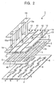
- the head frame 4 includes an outside frame portion 4a having a rectangular shape and three bridge portions 4b which are integrally formed with the outside frame portion 4a and which link the lateral sides of the outside frame portion 4a at a constant interval. Accordingly, four openings 5 having a rectangular shape are formed in parallel to each other (see Fig. 2 ). In the case in which the print head 1 is applied to a line printer which prints on 'A4' sized paper in a portrait orientation, the length of the openings 5 corresponds to the width of the size 'A4', that is, 21 cm.
- the head frame 4 is formed of a material having the same coefficient of linear expansion as a semiconductor substrate of the substrate member, which will be described below.
- silicon nitride is used for forming the head frame 4.
- alumina (Al 2 O 3 ), mullite, aluminum nitride, silicon carbide, etc. may be used from the group of ceramics, quartz (SiO 2 ), etc., may be used from the group of glass, and Invar, etc., may be used from the group of metals.
- the head frame 4 may have a thickness of, for example, 5 mm, and is sufficiently rigid.
- the nozzle-formed member 2 When the head frame 4 is laminated on the nozzle-formed member 2 at a high temperature such as 150°C, the nozzle-formed member 2 tries to shrink by a larger amount than the head frame 4 at a temperature lower than the laminating temperature (150°C), and thus becomes tense. Since the head frame 4 is sufficiently rigid, the interval between the ink-ejection nozzles 3, that is, a nozzle interval, varies in accordance with the coefficient of linear expansion of the head frame 4.
- the head frame 4 is laminated on the nozzle-formed member 2 by using, for example, a heat-setting adhesive sheet.
- a plurality of head chips HC are formed by laminating substrate members 6 on the nozzle-formed member 2. Accordingly, a plurality of head chips HC are formed on a single nozzle-formed member (see Fig. 2 ).
- Each of the substrate members 6 is constructed by forming heating elements 8 on a surface of a semiconductor substrate 7 formed of silicon, etc., and laminating a barrier layer 10 on the semiconductor substrate 7 at the same side as the side at which the heating elements 8 are formed (see Figs. 3 and 4 ).
- the barrier layer 10 defines side surfaces of ink-pressurizing cells 9; in other words, it serves as the side walls of the ink-pressurizing cells 9.
- the barrier layer 10 is formed of, for example, a dry film which is curable by light exposure, and is constructed by laminating the dry film over the entire surface of the semiconductor substrate 7, on which the heating elements 8 are formed, and removing unnecessary parts by a photolithography process. Accordingly, the substrate member 6 is completed.
- the thickness of the barrier layer 10 is approximately 12 ⁇ m, and the heating elements 8 have a square shape of which the length of each side is approximately 18 ⁇ m.
- the width of the ink-pressurizing cells 9 is approximately 25 ⁇ m.
- the substrate members 6 are laminated on the nozzle-formed member 2 by heat-curing the barrier layer 10 at approximately 105°C. Accordingly, the laminating temperature is mainly determined in accordance with the characteristics of the barrier layer 10. Although the laminating temperature of the nozzle-formed member 2 and the substrate members 6 is not limited to 105°C, it is necessary that the laminating temperature of the nozzle-formed member 2 and the head frame 4 be higher than the laminating temperature of the nozzle-formed member 2 and the substrate members 6. This will be explained with reference to a graph shown in Fig. 10 .
- Fig. 10 is a graph showing the relationship between the temperature and the interval between the ink-ejection nozzles 3 formed in the nozzle-formed member 2 (nozzle interval) and the relationship between the temperature and the interval between the heating elements 8 formed in the substrate members 6 (heater interval).
- curve A shows the relationship between the temperature and the nozzle interval, wherein the nozzle interval at room temperature (R.T.) is L 1 .
- curve B shows the relationship between the temperature and the heater interval, wherein the heater interval at room temperature (R.T.) is L 2 .
- the head frame 4 is laminated on the nozzle-formed member 2 at a temperature T 1 , at which curve A and curve B cross each other.
- the substrate members 6 are laminated on the nozzle-formed member 2 at a temperature T 2 , which is lower than T 1 .
- the nozzle-formed member 2 When the head frame 4 is laminated on the nozzle-formed member 2 at the temperature T 1 , the nozzle-formed member 2 tries to shrink by a larger amount than the head frame 4 at a temperature lower than the laminating temperature (T 1 ), and thus becomes tense.
- the interval between the ink-ejection nozzles 3, that is, the nozzle interval varies in accordance with the coefficient of linear expansion of the head frame 4. Since the coefficient of linear expansion of the head frame 4 is approximately the same as that of the substrate members 6, the nozzle interval and the heater interval become approximately the same at the same temperature. Accordingly, the displacements between the heating elements 8 and the ink-ejection nozzles 3 do not easily occur.
- the nozzle interval of a completed print head is determined by a required precision of a printer in which the print head is to be installed. Accordingly, L 2 is determined in a design phase.
- the required L 1 can be inversely calculated based on the graph shown in Fig. 10 from the coefficient of linear expansion ⁇ 1 of the nozzle-formed member 2, the coefficient of linear expansion ⁇ 2 of the semiconductor substrate 7 (which is also the coefficient of linear expansion of the head frame 4), the laminating temperature T 1 of the nozzle-formed member 2 and the head frame 4, and the temperature difference ⁇ T between the laminating temperature T 1 and room temperature (R.T.).
- L 2 may also be calculated from the following equation.
- L 1 L 2 ⁇ ⁇ 2 ⁇ ⁇ ⁇ T ⁇ 1 / ⁇ 1 ⁇ ⁇ ⁇ T ⁇ 1
- the nozzle interval at room temperature may be too small or large relative to the L 1 .
- an adjustment can be made by changing the laminating temperature of the head frame 4 and the nozzle-formed member 2.
- the head frame 4 may be laminated on the nozzle-formed member 2 at a temperature T 02 , which is higher than the laminating temperature T 1 determined at the design phase.
- the nozzle interval at room temperature (R.T.) is L 03 , which is larger than L 1
- the head frame 4 may be laminated on the nozzle-formed member 2 at a temperature T 03 , which is lower than the laminating temperature T 1 determined at the design phase.
- the coefficient of linear expansion of the head frame 4 is preferably lower than that of the nozzle-formed member 2.
- the nozzle-formed member 2 receives a force from the head frame 4 in either (1) an expanding direction or (2) a shrinking direction.
- the direction of the applied force is determined by the relationship between their coefficients of linear expansion.
- the nozzle-formed member 2 receives the force in the direction (2), there is a risk that concavities and convexities (wrinkles) will be formed in the nozzle-formed member 2.
- the nozzle-formed member 2 preferably receives the force in the direction (1), the expanding direction, rather than in the direction (2).
- the coefficient of linear expansion of the head frame 4 is lower than that of the nozzle-formed member 2 and approximately the same as that of the substrate members 6.
- the laminating temperature T 1 of the head frame 4 and the nozzle-formed member 2 is preferably higher than any temperatures at which following processes are performed. Accordingly, the nozzle-formed member 2 constantly receives a tension during the processes performed after the lamination of the head frame 4 and the nozzle-formed member 2, so that no wrinkles are formed.
- the head frame 4 is laminated on the nozzle-formed member 2 at 150°C, and then the substrate members 6 are laminated on the nozzle-formed member 2 at 105°C.
- a head unit 11 is formed by combining the head frame 4, the nozzle-formed member 2, and the substrate members 6, and ink-passage plates 12 are then attached to the head unit 11 (see Fig. 1 ).
- One ink-passage plate 12 is provided for one color, and four ink-passage plates 12 individually corresponding to four colors are provided in total (see Figs. 1 and 2 ).
- the ink-passage plates 12 are formed of a material which does not easily deform and which has ink resistance.
- Each of the ink-passage plates 12 includes a chamber portion 13 which fits into one of the openings 5 formed in the head frame 4, and a flange portion 14 which is integrally formed with the chamber portion 13 at one side thereof.
- the flange portion 14 is formed so as to have a size larger than the planer shape of the openings 5.
- the chamber portion 13 is provided with an opening 15 at the side opposite to the side at which the flange portion 14 is formed, and notches 16 for positioning the substrate members 6 are formed in the side walls of the opening 15 (see Figs. 3 and 4 ).
- the flange portion 14 is provided with an ink-supply tube 17, which projects from the side opposite to the side at which the chamber portion 13 is formed, and which is connected to the above-described opening 15 (see Figs. 1 , 2 , and 4 ).
- the notches 16 are arranged in two lines across the opening 15 in such a manner that end portions of the opposing notches 16 overlap each other in the direction in which they are arranged.
- the size of the notches 16 is determined such that the substrate members 6 can fit therein.
- Each of the ink-passage plates 12 is adhered to the head frame 4 in such a manner that the chamber portion 13 fits into the opening 5 and the flange portion 14 contacts the outside frame portion 4a and the bridge portions 4b of the head frame 4.
- the substrate members 6 laminated on the nozzle-formed member 2 are positioned inside the notches 16 formed in the chamber portion 13 and are adhered to the chamber portion 13 (see Figs. 3 and 4 ).
- ink-passage plates 12 By combining the ink-passage plates 12 with the head unit 11 as described above, closed spaces surrounded by the chamber portions 13 of the ink-passage plates 12 and the nozzle-formed member 2 are formed. These closed spaces are connected to the exterior environment only through the ink-supply tubes 17, and serve as ink passages 18 for transferring ink which is supplied through the ink-supply tubes to each of the ink-pressurizing cells 9. Accordingly, a single ink passage 18 is connected to a plurality of head chips HC, and the structure for supplying ink is made simpler than a print head in which the head chips are individually provided with ink passages.
- the substrate members 6 are individually fitted inside the notches 16, and are arranged in two rows in a zigzag manner so that end portions of the substrate members 6 overlap one another, and in such a manner that ink inlets 9a of the ink-pressurizing cells 9 oppose one another.
- the ink passage 18 is formed between the two rows of the substrate members 6, and the ink-pressurizing cells 9 are connected to the ink passage 18 via the ink inlets 9a (see Fig. 3 ).
- Each of the flexible substrates 19 is provided with connecting tabs 19a, which are inserted through openings 20 formed between the head frame 4 and the ink-passage plates 12 (see Fig. 4 ), and extend to the substrate members 6.
- the connecting tabs 19a are electrically connected to contact points (not shown), which are individually connected to the heating elements 8 formed in the substrate members 6.
- the ink-supply tubes 17 provided on the ink-passage plates 12 are individually connected to ink tanks (not shown), which individually contain inks of different colors, and the ink passages 18 and the ink-pressurizing cells 9 are filled with ink supplied from the ink tanks.
- the corresponding heating elements 8 are rapidly heated. Accordingly, at each of the corresponding heating elements 8, a bubble of ink vapor (ink bubble) is generated at the surface thereof. Then, as the ink bubble expands, a certain volume of ink is pushed ahead, and the same volume of ink is ejected out from the corresponding ink-ejection nozzle 3 as an ink drop. The ink drop, which is ejected from the ink-ejection nozzle h, adheres (lands on) to a print medium such as a piece of paper, etc. Then, the ink-pressurizing cells 9 from which the ink drops are ejected are immediately refilled with ink through the ink passages 18 by the same amount as the ejected ink drops.
- a current pulse is applied for a short time such as 1 to 3 ⁇ s to some of the heating elements 8 selected in accordance with a command issued by the control unit of the printer, the corresponding heating elements 8 are rapidly heated. Accordingly, at each of the
- the nozzle-formed member 2 is formed by an electroforming technique, and is disposed on a supporting jig 21 having a flat surface (see Fig. 5 ).
- the reason why the nozzle-formed member 2 is disposed on the supporting jig 21 is because the nozzle-formed member 2 is extremely thin and it cannot maintain its shape by itself.
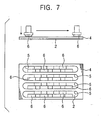
- the head frame 4 is laminated on the nozzle-formed member 2 disposed on the supporting jig 21 by heating a heat-setting adhesive sheet, for example, an epoxy adhesive sheet, at 150°C (see Fig. 6 ).
- a heat-setting adhesive sheet for example, an epoxy adhesive sheet
- reference numerals 2' and 4' schematically show the shapes of the nozzle-formed member 2 and the head frame 4 which extend by being heated to 150°C.
- Fig. 7 only schematically shows the laminating step, and only seven substrate members 6 are shown for each color.
- the head unit 11 is completed (see Fig. 8 ), and an ink-passage unit 22, which is constructed by another process, is attached to the head unit 11 (see Fig. 9 ).
- the ink-passage unit 22 is constructed by combining the above-described four ink-passage plates 12 using a connecting member (not shown).
- the head frame 4 which has approximately the same coefficient of linear expansion as that of the semiconductor substrates 7 (for example, silicon substrates) which are the base substrates of the substrate members 6, is first laminated on the nozzle-formed member 2.
- the head frame 4. Then, the substrate members 6 are laminated on the nozzle-formed member 2 at a temperature lower than the laminating temperature of the head frame 4 and the nozzle-formed member 2. Accordingly, the interval between the ink-ejection nozzles 3 formed in the nozzle-formed member 2 and the interval between the heating elements 8 formed in the substrate members 6 are always the same at temperatures lower than the laminating temperature of the nozzle-formed member 2 and the head frame 4.
- a print head having improved characteristics of ink drop ejection can be obtained.
- the size of the print head 1 can be easily increased, and thus the print head 1 is especially suitable for long print heads such as print heads for line printers, etc.
- the nozzle-formed member 2 obtains high rigidity.
- the head chips HC are disposed in a zigzag manner in the above-described print head, even when head chips HC having different printing characteristics are arranged, print mottling can be made less conspicuous.
- a plurality of head chips HC are formed on a single nozzle-formed member, positional accuracy of the ink-ejection nozzles can be increased and the printing characteristics can be improved.
- a single ink passage is connected to a plurality of head chips HC, the structure for supplying ink to each of the head chips HC can be made simpler.
- the above-described print head 1 is suitable as a print head that is long in a direction perpendicular to the feed direction of a print medium, and is especially suitable as a line head. Accordingly, print speed can be increased.
- the present invention was applied to a print head for a full-color, bubble ink jet printer in the above-described embodiment, the present invention may also be applied to print heads for monocolor printers.
- the present invention is not limited to the above-described structure in which the four print heads for four colors are combined, and an individual print head may be prepared for each color.
- a print head 30 of according to the second embodiment includes the substrate members 6 and the nozzle-formed members 2 which have approximately the same coefficient of linear expansion.
- various adhesives including heat-setting adhesives can be used in the fabrication process.
- the present invention was applied to a line head which prints on 'A4' sized paper in a portrait orientation in the second direction, the present invention may also be applied to other print heads such as serial heads, etc.
- the print head 30 was constructed of a plurality of substrate members 6 in the second embodiment, the present invention is not limited to this, and a line of 21 cm can also be covered by a single substrate member 6.
- the length of the substrate member 6 is increased as described above, the influence of the difference in the coefficients of linear expansion between the substrate members 6 and the nozzle-formed member 2 is increased. Accordingly, in such a case, the use of the print head according to the present invention becomes more advantageous.
- the print head 30 according to the second embodiment will be further illustrated below.
- the print head 30 may be manufactured by a following process using a silicon wafer (single-crystal silicon) as a material of the semiconductor substrates 7, which are the base members of the substrate members 6, a dry film resist as a material of the barrier layer 10, and Invar alloy as a material of the nozzle-formed member 2.
- a silicon wafer single-crystal silicon
- the semiconductor substrates 7 which are the base members of the substrate members 6, a dry film resist as a material of the barrier layer 10, and Invar alloy as a material of the nozzle-formed member 2.
- the ink-ejection nozzles 3 are formed in the nozzle-formed member 2 by a spray etching process using a ferric chloride solution.
- the heating elements (heaters) 8 are formed by laminating a thin film layer on the semiconductor substrate 7 formed of the silicon wafer, and then the dry film resist is laminated on the semiconductor substrate 7. Then, the side walls of the ink-pressurizing cells 9 are formed by removing unnecessary parts of the dry film resist by a photolithography process. Accordingly, the substrate member 6 is formed.
- the substrate members 6 and the nozzle-formed member 2 are positioned relative to each other, and are laminated by heating them at 150°C for 15 minutes.
- Invar alloy of which the nozzle-formed member 2 is formed, consists of 64% ferrum (Fe) and 36% nickel (Ni), and, as can be seen from a graph shown in Fig. 13 , has a coefficient of linear expansion of 1.2 ⁇ 10 -6 .
- the coefficient of linear expansion of Invar alloy is almost the same as that of silicon (2.6 ⁇ 10 -6 ), which is the base material of the substrate member 6.
- Invar alloy consists of 64% ferrum (Fe) and 36% nickel (Ni), and has the coefficient of linear expansion of 1.2 ⁇ 10 -6 , which is the minimum value in the graph shown in Fig. 13 .
- the coefficient of linear expansion becomes higher than the minimum value (see Fig. 13 ).
- an alloy in which the content of ferrum (Fe) is adjusted around 64% so that the difference in coefficients of linear expansion between the silicon and the alloy is reduced, may also be used.
- the print head 30 may also have the following construction.
- the base material of the substrate members 6 and the material of the barrier layer 10 are the same as described above, and Pyrex glass (which is a trademark of Corning Inc. for a hard glass, No. 7740), is used as the material for the nozzle-formed member 2.
- Pyrex glass which is a trademark of Corning Inc. for a hard glass, No. 7740
- the coefficient of linear expansion of Pyrex glass is 3.3 ⁇ 10 -6 .
- the ink-ejection nozzles 3 are formed in the nozzle-formed member 2 by a reactive ion etching (RIE) process using a chromium layer as a mask.
- RIE reactive ion etching
- the print head 30 constructed as described above When the print head 30 constructed as described above is used for printing, the displacements hardly occur, and degradation of the printing quality can be prevented.
- the print head 30 may also be, for example, a line head (size 'A6') having a length of 105 mm, in which one substrate member 6 is laminated on one nozzle-formed member 2.
- the base material of the substrate member 6, the material of the barrier layer 10, and the material of the nozzle-formed member 2 may be the same as described above.
- the displacements between the heating elements 8 and the ink-ejection nozzles 3, and between the ink-pressurizing cells 9 and the ink-ejection nozzles 3, are also extremely small. Even the maximum displacement between the heating elements 8 and the ink-pressurizing cells 9 is only several micrometers. Accordingly, degradation of the printing quality is almost completely prevented.
- the head frame 4 formed of a material having the same coefficient of linear expansion as the semiconductor substrate 7, which is the base substrate of the substrate member 6, is laminated on the nozzle-formed member 2 at a high temperature. Then, the substrate member 6 may be laminated on the nozzle-formed member 2 at a lower temperature than the laminating temperature of the head frame 4 and the nozzle-formed member 2.
- the interval between the ink-ejection nozzles 3 formed in the nozzle-formed member 2 varies in accordance with the coefficient of linear expansion of the head frame 4. Since the coefficient of linear expansion of the head frame 4 is approximately the same as that of the substrate member 6, the intervals between the heating elements 8 and the ink-pressurizing cells 9 formed on the substrate member 6, and the interval between the ink-ejection nozzles 3 formed in the nozzle-formed member 2 vary at the same rate. Accordingly, the problem which occurs due to the displacements between the heating elements c and the ink-ejection nozzles 3, and between the ink-pressurizing cells 9 and the ink-ejection nozzles 3, can be avoided.
- the coefficient of linear expansion of the head frame 4 is preferably lower than that of the nozzle-formed member 2.
- the head frame 4 will warp due to the difference in coefficients of linear expansion between the head frame 4 and the nozzle-formed member 2.
- the nozzle-formed member 2 shrinks at a higher rate compared to the head frame 4 when the environmental temperature is reduced from the laminating temperature. Accordingly, there is a risk that the head frame 4 will warp in such a manner that the side surface on which the nozzle-formed member 2 is laminated becomes concave (see Fig. 14 ).
- an object of the third embodiment is to prevent warping of a lamination surface of the frame member, that is, a surface on which the nozzle-formed member is laminated, and to avoid the problem which occurs due to the warping of the lamination surface of the frame member.
- a warp-suppressing member 101 is laminated on a surface 4d of the head frame 4 which is at the opposite side of a lamination surface 4c, on which the nozzle-formed member 2 is laminated.
- the warp-suppressing member 101 is preferably formed of nickel or a material comprising nickel.
- the warp-suppressing member 101 is laminated on the head frame 4 at the same temperature as the laminating temperature of the nozzle-formed member 2 and the head frame 4. In the above-described case, the warp-suppressing member 101 is laminated on the head frame 4 at 150°C.
- the two surfaces 4c and 4d at the opposite sides of the head frame 4 receive the same tension at the operating temperature. Accordingly, the head frame 4 can be prevented from warping.
- Figs. 16 and 17 show an example of a manufacturing method for a print head according to the third embodiment of the present invention.
- a lamination surface 201a of a head frame 201, on which the nozzle-formed member 2 is to be laminated, is formed so as to be convex, and a surface 201b at the opposite side of the lamination surface 201a is formed so as to be flat.
- the curvature of the lamination surface 201a is determined such that deformation of the head frame 201, which occurs at the operating temperature due to the difference in coefficients of linear expansion between the head frame 201 and the nozzle-formed member 2, can be compensated for.
- the nozzle-formed member 2 is laminated on the lamination surface 201a of the head frame 201 at a temperature higher than the operating temperature, for example, at 150°C (see Fig. 16 ).
- the lamination surface 201a of the head frame 201 deforms at the operating temperature due to a shrinking force of the nozzle-formed member 2.
- the lamination surface 201a is formed so as to be convex at first, the lamination surface 201a becomes flat by receiving the shrinking force (see Fig. 17 ).
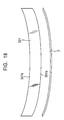
- Figs. 18 and 19 show another example of a manufacturing method for a print head according to the third embodiment of the present invention.
- a lamination surface 301a on which the nozzle-formed member 2 is to be laminated, becomes convex. Accordingly, a surface 301b at the opposite side of the lamination surface 301a becomes concave (see Fig. 18 ).
- the curvature of the lamination surface 301a is determined such that deformation of the head frame 301, which occurs at the operating temperature due to the difference in coefficients of linear expansion between the head frame 301 and the nozzle-formed member 2, can be compensated for.
- the nozzle-formed member 2 is laminated on the lamination surface 301a of the head frame 301 at a temperature higher than the operating temperature, for example, at 150°C (see Fig. 18 ).
- the lamination surface 301a of the head frame 301 deforms at the operating temperature due to a shrinking force of the nozzle-formed member 2.
- the lamination surface 301a is formed so as to be convex at first, the lamination surface 301a becomes flat by receiving the shrinking force (see Fig. 19 ).
- Fig. 20 shows a print head according to a fourth embodiment of the present invention, and an object of the fourth embodiment is the same as that of the third embodiment.
- intervals D between heating elements, between ink-pressurizing cells, and between ink-ejection nozzles are increased from the central portion (C.P.) toward the peripheral portion (P.P.). More specifically, the relationship between the intervals can be expressed as follows: D ⁇ 1 ⁇ D ⁇ 2 ⁇ D ⁇ 3 ⁇ D ⁇ 4 ⁇ D ⁇ 5
- the lamination surface 4c of the head frame 4 becomes concave.
- ejecting directions (shown by the arrows in Fig. 20 ) of the ink drops at positions farther from the central portion (C.P.) and closer to the peripheral portion (P.P.) are tilted toward the center.
- intervals d between the landing points on the print medium become even from the central portion (C.P.) to the peripheral portion (P.P.), and the state shown in Fig. 14 , in which the intervals between the landing points become narrower toward the peripheral portion, can be avoided.
- the relationship between the intervals between the landing points can be expressed as follows: d ⁇ 1 ⁇ d ⁇ 2 ⁇ d ⁇ 3 ⁇ d ⁇ 4 ⁇ d ⁇ 5
- the time to apply current to the heating elements 8 is adjusted such that the heating elements 8 positioned closer to the central portion receive current earlier than the heating elements 8 positioned closer to the peripheral portion.
- the distances between the ink-ejection nozzles 3 and the print medium k become shorter toward the peripheral portion.
- the time to apply current to the heating elements 8 is adjusted such that the heating elements 8 positioned closer to the central portion receive current earlier than the heating elements 8 positioned closer to the peripheral portion.
- the heating elements 8 disposed at positions at which the travel time of the ink drops is longer receive current earlier, so that the ink drops are ejected earlier.
- the ink drops ejected by all the heating elements 8 land on the print medium at the same time. Accordingly, when the print head is applied to a line printer, printed lines become straight from the central portion to the peripheral portion, and high printing quality can be maintained.
- An object of the fifth embodiment is to reduce the displacements as much as possible between the ink-pressurizing cells, which are individually provided with heating elements and the ink-ejection nozzles, which individually correspond to the ink-pressurizing cells, and to increase the rigidity of the print head.
- a print head 500 according to the fifth embodiment of the present invention is a print head used in a full-color, bubble ink jet printer.
- the print head 500 includes a nozzle-formed member 2, in which a plurality of ink-ejection nozzles 3 are formed. Several hundred ink-ejection nozzles 3 are formed in a single substrate member, which will be described below. Also in the fifth embodiment, the nozzle-formed member 2 is formed of nickel or a material comprising nickel in the shape of, for example, a sheet having a thickness of 15 to 20 ⁇ m by an electroforming technique, and the ink-ejection nozzles 3 having a diameter of approximately 20 ⁇ m are formed in the nozzle-formed member 2 (see Figs. 22 , 23 , and 24 ).
- the nozzle-formed member 2 is laminated to a head frame 24, in which a plurality of head-chip-receiving holes 25 are formed.
- the head-chip-receiving holes 25 can be divided into four groups, which individually correspond to four colors. In each of the groups, head-chip-receiving holes 25 are arranged in the longitudinal direction thereof in a zigzag manner.
- the head-chip-receiving holes 25 individually correspond to head chips HC, which will be described below, so that the head chips HC can be disposed therein (see Fig. 22 ).
- the length of each of the groups of the head-chip-receiving holes 25 corresponds to the width of the size 'A4', that is, 21 cm.
- the head frame 24 is formed of a material having the same coefficient of linear expansion as a semiconductor substrate of the substrate member, which will be described below.
- silicon nitride is used for forming the head frame 24.
- alumina (Al 2 O 3 ), mullite, aluminum nitride, silicon carbide, etc. may be used from the group of ceramics, quartz (SiO 2 ), etc., may be used from the group of glass, and Invar, etc., may be used from the group of metals.
- the head frame 24 may have a thickness of, for example, 5 mm, and is sufficiently rigid.
- the nozzle-formed member 2 When the head frame 24 is laminated on the nozzle-formed member 2 at a high temperature such as 150°C, the nozzle-formed member 2 tries to shrink by a larger amount than the head frame 24 at a temperature lower than the laminating temperature (150°C), and thus becomes tense. Since the head frame 24 is sufficiently rigid, the interval between the ink-ejection nozzles 3, that is, a nozzle interval, varies in accordance with the coefficient of linear expansion of the head frame 24.
- the head frame 24 is laminated on the nozzle-formed member 2 by using, for example, a heat-setting adhesive sheet.
- a plurality of head chips HC are formed by laminating substrate members 6 on the nozzle-formed member 2. Accordingly, a plurality of head chips HC are formed on a single nozzle-formed member (see Fig. 22 ).
- the substrate members 6 are the same as those in the first embodiment, and explanations thereof are thus omitted.
- the thickness of the barrier layer 10 is approximately 12 ⁇ m, and the heating elements 8 have a square shape of which the length of each side is approximately 18 ⁇ m.
- the width of the ink-pressurizing cells 9 is approximately 25 ⁇ m.
- a case is considered in which the print head 500 is applied to a line printer which prints on 'A4' sized paper in a portrait orientation.
- the print head 500 is applied to a line printer which prints on 'A4' sized paper in a portrait orientation.
- a single group of head-chip-receiving holes 25 formed in the head frame 24 approximately five thousand ink-ejection nozzles 3 are formed in the nozzle-formed member 2 and sixteen substrate members 6 are laminated thereon. Since is impossible to show the accurate numbers of ink-ejection nozzles 3 with accurate dimensions in the drawings which are limited in size, the drawings are partly exaggerated and elements are sometimes omitted in order to facilitate understanding.
- the head frame 24 and the nozzle-formed member 2 are laminated together at 150°, and then the substrate members 6 are laminated to the nozzle-formed member 2 at approximately 105°.
- a head unit 11 is formed by combining the head frame 24, the nozzle-formed member 2, and the substrate members 6, and ink-passage plates 12 are then attached to the head unit 11 (see Fig. 21 ).
- One ink-passage plate 12 is provided for one color, and four ink-passage plates 12 individually corresponding to four colors are provided in total (see Figs. 21 and 22 ).
- the ink-passage plates 12 are formed of a material which does not easily deform and which has ink resistance.
- each of the ink-passage plates 12 includes a flange portion 14 having the shape like a plate of which the size is larger than a region including the head-chip-receiving holes 25, and chamber portions 13 which protrude from one side of the flange portion 14.
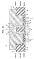
- Fig. 24 shows a sectional view of Fig. 23 cut along line XXIV-XXIV at a part including two head-chip-receiving holes 25.
- the size of the chamber portions 13 is determined such that they can be individually fitted inside the head-chip-receiving holes 25, and that concavities 26 are formed so that there are clearances in the head-chip-receiving holes 25.
- Each of the concavities 26 forms an ink passage 18, which will be described below.
- the chamber portions 13 are individually provided with notches 16 at the edge thereof.
- the notches 16 are connected to the concavities 26, and are large enough that the substrate members 6 can be fitted therein.
- the notches 16 are formed in two rows in a zigzag manner so that the concavities 26 oppose one another and end portions of the notches overlap one another in the direction in which they are arranged.
- the flange portion 14 of the ink-passage plate 12 is provided with an ink-supply passage 27 which extends in the longitudinal direction of the flange portion 14 at the midsection thereof.
- the ink-supply passage 27 is connected to the concavities 26 formed in the chamber portions 13.
- the flange portion 14 of the ink-passage plate 12 is also provided with an ink-supply tube 17, which projects from the side opposite to the side at which the chamber portions 13 are formed, and which is connected to the above-described ink-supply passage 27 (see Figs. 21 , 22 , and 24 ).
- Fig. 25 is a sectional view of Fig. 23 cut along line XXV-XXV
- Fig. 26 is a sectional view of Fig. 23 cut along line XXVI-XXVI.
- the flange portion 14 contacts the head frame 24 at position shown in Fig. 26 .
- the substrate members 6 laminated on the nozzle-formed member 2 are positioned inside the notches 16 formed in the chamber portions 13 and are adhered to the chamber portions 13 (see Figs. 23 and 24 ).
- closed spaces surrounded by the chamber portions 13 of the ink-passage plates 12 and the nozzle-formed member 2 are formed. These closed spaces include ink-supply passages 27, the concavities 26, and the ink passages 18, and are connected to the exterior environment only through the ink-supply tubes 17. Ink which is supplied through the ink-supply passages 27 is transferred through the ink passages 18 to each of the ink-pressurizing cells 9.
- Fig. 27 is a sectional view of Fig. 24 cut along line XXVII-XXVII.
- the head-chip-receiving holes 25 are arranged across the ink-supply passage 27.
- Fig. 28 is a sectional view of Fig. 24 cut along line XXVIII-XXVIII.
- the head-chip-receiving holes 25 are individually provided with the ink-passages 18.
- Each of the flexible substrates 19 is provided with connecting tabs 19a, which are inserted through openings 20 formed between the head frame 4 and the ink-passage plates 12 (see Fig. 24 ), and extend to the substrate members 6.
- the connecting tabs 19a are electrically connected to contact points (not shown), which are individually connected to the heating elements 8 formed in the substrate members 6.
- the ink-supply tubes 17 provided on the ink-passage plates 12 are individually connected to ink tanks (not shown), which individually contain inks of different colors, and the ink-supply passages 27, the ink passages 18, and the ink-pressurizing cells 9 are filled with ink supplied from the ink tanks.
- the corresponding heating elements 8 are rapidly heated. Accordingly, at each of the corresponding heating elements 8, a bubble of ink vapor (ink bubble) is generated at the surface thereof. Then, as the ink bubble expands, a certain volume of ink is pushed ahead, and the same volume of ink is ejected out from the corresponding ink-ejection nozzle 3 as an ink drop. The ink drop, which is ejected from the ink-ejection nozzle h, adheres (lands on) to a print medium such as a piece of paper, etc. Then, the ink-pressurizing cells 9 from which the ink drops are ejected are immediately refilled with ink through the ink passages 18 by the same amount as the ejected ink drops.
- a current pulse is applied for a short time such as 1 to 3 ⁇ s to some of the heating elements 8 selected in accordance with a command issued by the control unit of the printer, the corresponding heating elements 8 are rapidly heated. Accordingly, at each of the
- the nozzle-formed member 2 is formed by an electroforming technique, and is disposed on a supporting jig 21 having a flat surface (see Fig. 29 ).
- the reason why the nozzle-formed member 2 is disposed on the supporting jig 21 is because the nozzle-formed member 2 is extremely thin and it cannot maintain its shape by itself.
- the head frame 24 is laminated on the nozzle-formed member 2 disposed on the supporting jig 21 by heating a heat-setting adhesive sheet, for example, an epoxy adhesive sheet, at 150°C (see Fig. 30 ).
- a heat-setting adhesive sheet for example, an epoxy adhesive sheet
- reference numerals 2' and 24' schematically show the shapes of the nozzle-formed member 2 and the head frame 24 which extend by being heated to 150°C.
- Fig. 31 only schematically shows the laminating step, and only seven substrate members 6 are shown for each color.
- the head unit 11 is completed (see Fig. 32 ), and an ink-passage unit 22, which is constructed by another process, is attached to the head unit 11 (see Fig. 33 ).
- the ink-passage unit 22 is constructed by combining the above-described four ink-passage plates 12 using a connecting member (not shown).
- the head frame 24 which has approximately the same coefficient of linear expansion as that of the semiconductor substrates 7 (for example, silicon substrates) which are the base substrates of the substrate members 6, is first laminated on the nozzle-formed member 2. Then, the substrate members 6 are laminated on the nozzle-formed member 2 at a temperature lower than the laminating temperature of the head frame 24 and the nozzle-formed member 2. Accordingly, the interval between the ink-ejection nozzles 3 formed in the nozzle-formed member 2 and the interval between the heating elements 8 formed in the substrate members 6 are always the same at temperatures lower than the laminating temperature of the nozzle-formed member 2 and the head frame 24. Thus, a print head having improved characteristics of ink drop ejection can be obtained.
- the semiconductor substrates 7 for example, silicon substrates
- the size of the print head 500 can be easily increased, and thus the print head 500 is especially suitable for long print heads such as print heads for line printers, etc.
- the head frame 24 is provided with a plurality of head-chip-receiving holes 25 which extend in the longitudinal direction thereof, the head frame 24 is rigid in the longitudinal direction. Accordingly, by laminating the head frame 24 on the nozzle-formed member 2, the nozzle-formed member 2 obtains high rigidity. Thus, as described above, it is possible to form a print head for a line printer in which four print heads for four colors are combined.
- the head chips HC are disposed in a zigzag manner in the above-described print head, even when head chips HC having different printing characteristics are arranged, print mottling can be made less conspicuous.
- a plurality of head chips HC are formed on a single nozzle-formed member, positional accuracy of the ink-ejection nozzles can be increased and the printing characteristics can be improved.
- the above-described print head 500 is suitable as a print head that is long in a direction perpendicular to the feed direction of a print medium, and is especially suitable as a line head. Accordingly, print speed can be increased.
Claims (7)
- Tête d'impression ayant au moins des cellules de mise sous pression d'encre (9), des éléments chauffants (8) et des buses d'éjection d'encre (3), la tête d'impression (1) comprenant :une pluralité d'éléments formant supports (6) qui forment des surfaces latérales et une surface d'extrémité des cellules de mise sous pression d'encre (9) et qui sont dotés d'éléments chauffants (8) ;un élément formant buse (2) qui forme l'autre surface d'extrémité des cellules de mise sous pression d'encre (9), et dans lequel sont formées les buses d'éjection d'encre (3) qui correspondent individuellement aux cellules de mise sous pression d'encre (9) ;un châssis de tête (4) qui supporte l'élément formant buse (2) ; etune pluralité de puces de tête (HC) qui sont construites en laminant les éléments formant supports (6) sur un élément formant buse (6) commun de sorte que les buses d'éjection d'encre (3) correspondent individuellement aux cellules de mise sous pression d'encre (9),dans laquelle les puces de tête (HC) sont agencées dans une direction perpendiculaire à une direction d'alimentation d'un support d'impression, etdans laquelle le châssis de tête (4) est prévu avec des trous de réception de puce de tête (5),caractérisée en ce que :chaque trou de réception de puce de tête (5) reçoit une pluralité de puces de tête (HC) qui sont agencées sur deux rangées en zigzag de sorte que les parties d'extrémité des puces de tête (HC) se chevauchent dans leur direction longitudinale et en ce que :les puces de tête (HC) sont agencées dans le trou de réception de puce de tête (5) de sorte que des entrées d'encre (9a) des cellules de mise sous pression d'encre (9) des puces de tête (HC) sont opposées entre elles et un passage d'encre (18) est formé entre les puces de tête (HC) qui s'opposent entre elles.
- Tête d'impression selon la revendication 1, comprenant en outre une plaque de passage d'encre (12) qui recouvre le châssis de tête (4) du côté opposé au côté sur lequel les puces de tête (HC) sont formées et qui est utilisée pour alimenter chacune des puces de tête (HC) avec de l'encre,
dans laquelle la plaque de passage d'encre (12) est prévue avec des parties de chambre (13) qui sont individuellement montées dans les trous de réception de puce de tête (5) et les puces de tête (HC) sont individuellement disposées à l'intérieur des encoches (16) qui sont individuellement formées dans les parties de chambre (13) au niveau de leur bord. - Tête d'impression selon la revendication 1, dans laquelle le châssis de tête (4) et les éléments formant supports (6) ont approximativement le même coefficient de dilatation linéaire.
- Tête d'impression selon la revendication 1, dans laquelle un coefficient de dilatation linéaire de l'élément formant buse (2) est supérieur à un coefficient de dilatation thermique du châssis de tête (4).
- Tête d'impression selon la revendication 1, dans laquelle une pluralité d'unités formant supports, dont chacune comprend un ou plusieurs éléments formant supports (6), sont prévues pour éjecter individuellement des encres de différentes couleurs, et dans laquelle les éléments formant supports (6) compris dans les unités formant supports sont fixés sur un seul élément formant buse (2).
- Tête d'impression selon la revendication 1, dans laquelle la tête d'impression (1) est une tête linéaire.
- Tête d'impression selon la revendication 1, dans laquelle l'élément formant buse (2) est formé avec un matériau comprenant du nickel.
Applications Claiming Priority (6)
| Application Number | Priority Date | Filing Date | Title |
|---|---|---|---|
| JP2000240841A JP3608484B2 (ja) | 2000-08-09 | 2000-08-09 | プリントヘッド、その製造方法及びその制御方法 |
| JP2000248435 | 2000-08-18 | ||
| JP2000276554A JP2002086727A (ja) | 2000-09-12 | 2000-09-12 | プリントヘッド |
| JP2001138431A JP3608526B2 (ja) | 2000-08-18 | 2001-05-09 | プリントヘッド及びその製造方法並びにプリンター。 |
| JP2001216402A JP3636109B2 (ja) | 2001-07-17 | 2001-07-17 | プリントヘッド |
| EP01119074A EP1179430B1 (fr) | 2000-08-09 | 2001-08-07 | Tête d'impression et son procédé de fabrication |
Related Parent Applications (2)
| Application Number | Title | Priority Date | Filing Date |
|---|---|---|---|
| EP01119074A Division EP1179430B1 (fr) | 2000-08-09 | 2001-08-07 | Tête d'impression et son procédé de fabrication |
| EP01119074.1 Division | 2001-08-07 |
Publications (2)
| Publication Number | Publication Date |
|---|---|
| EP1657065A1 EP1657065A1 (fr) | 2006-05-17 |
| EP1657065B1 true EP1657065B1 (fr) | 2010-11-10 |
Family
ID=27531636
Family Applications (6)
| Application Number | Title | Priority Date | Filing Date |
|---|---|---|---|
| EP06001852A Expired - Lifetime EP1657065B1 (fr) | 2000-08-09 | 2001-08-07 | Tête d'impression, son procédé de fabrication et imprimante |
| EP06001854A Expired - Lifetime EP1666256B1 (fr) | 2000-08-09 | 2001-08-07 | Tête d'impression, son procédé de fabrication et imprimante |
| EP06001851A Expired - Lifetime EP1657064B1 (fr) | 2000-08-09 | 2001-08-07 | Tête d'impression, son procédé de fabrication et imprimante |
| EP06001853A Expired - Lifetime EP1657066B1 (fr) | 2000-08-09 | 2001-08-07 | Tête d'impression, son procédé de fabrication et imprimante |
| EP06001850A Expired - Lifetime EP1657063B1 (fr) | 2000-08-09 | 2001-08-07 | Tête d'impression, son procédé de fabrication et imprimante |
| EP01119074A Expired - Lifetime EP1179430B1 (fr) | 2000-08-09 | 2001-08-07 | Tête d'impression et son procédé de fabrication |
Family Applications After (5)
| Application Number | Title | Priority Date | Filing Date |
|---|---|---|---|
| EP06001854A Expired - Lifetime EP1666256B1 (fr) | 2000-08-09 | 2001-08-07 | Tête d'impression, son procédé de fabrication et imprimante |
| EP06001851A Expired - Lifetime EP1657064B1 (fr) | 2000-08-09 | 2001-08-07 | Tête d'impression, son procédé de fabrication et imprimante |
| EP06001853A Expired - Lifetime EP1657066B1 (fr) | 2000-08-09 | 2001-08-07 | Tête d'impression, son procédé de fabrication et imprimante |
| EP06001850A Expired - Lifetime EP1657063B1 (fr) | 2000-08-09 | 2001-08-07 | Tête d'impression, son procédé de fabrication et imprimante |
| EP01119074A Expired - Lifetime EP1179430B1 (fr) | 2000-08-09 | 2001-08-07 | Tête d'impression et son procédé de fabrication |
Country Status (4)
| Country | Link |
|---|---|
| US (4) | US6663223B2 (fr) |
| EP (6) | EP1657065B1 (fr) |
| DE (5) | DE60128606T9 (fr) |
| SG (2) | SG126682A1 (fr) |
Families Citing this family (29)
| Publication number | Priority date | Publication date | Assignee | Title |
|---|---|---|---|---|
| AUPP654598A0 (en) * | 1998-10-16 | 1998-11-05 | Silverbrook Research Pty Ltd | Micromechanical device and method (ij46h) |
| AU1139100A (en) * | 1998-10-16 | 2000-05-08 | Silverbrook Research Pty Limited | Improvements relating to inkjet printers |
| US6604810B1 (en) * | 2000-05-23 | 2003-08-12 | Silverbrook Research Pty Ltd | Printhead capping arrangement |
| JP3598957B2 (ja) * | 2000-09-12 | 2004-12-08 | ソニー株式会社 | プリントヘッドの製造方法 |
| CN1222418C (zh) * | 2000-10-20 | 2005-10-12 | 西尔弗布鲁克研究有限公司 | 笔用打印头 |
| US6874865B2 (en) * | 2001-09-10 | 2005-04-05 | Sony Corporation | Printer head chip and printer head |
| US7188925B2 (en) | 2004-01-30 | 2007-03-13 | Hewlett-Packard Development Company, L.P. | Fluid ejection head assembly |
| US7156486B2 (en) * | 2004-02-23 | 2007-01-02 | Sony Corporation | Liquid ejection head, liquid ejection apparatus, and manufacturing method of the liquid ejection head |
| JP4041989B2 (ja) * | 2004-02-23 | 2008-02-06 | ソニー株式会社 | 液体吐出ヘッド、液体吐出装置及び液体吐出ヘッドの製造方法 |
| CN1980795B (zh) * | 2004-04-30 | 2011-08-17 | 富士胶片戴麦提克斯公司 | 液滴喷射装置 |
| DE602005021876D1 (de) * | 2004-04-30 | 2010-07-29 | Dimatix Inc | Rezirkulationsanordnung |
| US7325309B2 (en) * | 2004-06-08 | 2008-02-05 | Hewlett-Packard Development Company, L.P. | Method of manufacturing a fluid ejection device with a dry-film photo-resist layer |
| US8353705B2 (en) * | 2004-08-16 | 2013-01-15 | Incom Corporation | Attendance tracking system |
| JP2006224318A (ja) * | 2005-02-15 | 2006-08-31 | Brother Ind Ltd | インクジェット記録装置 |
| US20070008375A1 (en) * | 2005-06-24 | 2007-01-11 | Toru Tanikawa | Head module, liquid ejection head, liquid ejection apparatus, and method of fabricating head module |
| DE102005060785A1 (de) * | 2005-12-16 | 2007-06-28 | Man Roland Druckmaschinen Ag | Verfahren zum Betreiben einer Inkjet-Druckeinrichtung |
| KR20080067937A (ko) | 2007-01-17 | 2008-07-22 | 삼성전자주식회사 | 화상형성장치 및 그 잉크분사방법 |
| US8517508B2 (en) * | 2009-07-02 | 2013-08-27 | Fujifilm Dimatix, Inc. | Positioning jetting assemblies |
| USD652446S1 (en) | 2009-07-02 | 2012-01-17 | Fujifilm Dimatix, Inc. | Printhead assembly |
| USD653284S1 (en) | 2009-07-02 | 2012-01-31 | Fujifilm Dimatix, Inc. | Printhead frame |
| DE102010011496A1 (de) * | 2010-03-16 | 2011-09-22 | GM Global Technology Operations LLC , (n. d. Ges. d. Staates Delaware) | Verfahren zur selektiven Anzeige von Informationen eines Kamerasystems in einer Anzeigevorrichtung eines Fahrzeugs und Fahrzeug mit einem Kamerasystem |
| WO2012023939A1 (fr) * | 2010-08-19 | 2012-02-23 | Hewlett-Packard Development Company, L.P. | Ensemble tête d'impression à jet d'encre à groupement large comportant un écran |
| DE102011086056A1 (de) * | 2011-11-10 | 2013-05-16 | Hochschule Heilbronn Institut für angewandte Forschung | Vorrichtung zum Aufbringen von Flüssigkeiten auf Warenbahnen |
| JP6312654B2 (ja) | 2012-04-17 | 2018-04-18 | カティーバ, インコーポレイテッド | インクジェット印刷システムと共に使用するための印刷ヘッドユニットアセンブリ |
| TWI540056B (zh) * | 2012-05-11 | 2016-07-01 | 凱特伊夫公司 | 用於與噴墨列印系統一起使用的列印噴頭單元總成 |
| JP6089561B2 (ja) * | 2012-10-10 | 2017-03-08 | 株式会社リコー | 液滴吐出ヘッドおよびそれを備えた液滴吐出装置ならびにインクジェット記録装置 |
| US9211712B2 (en) * | 2013-12-27 | 2015-12-15 | Palo Alto Research Center Incorporated | Injection molded ink jet modules |
| US10457059B2 (en) | 2016-07-18 | 2019-10-29 | Kateeva, Inc. | Printing system assemblies and techniques |
| EP3560141A4 (fr) | 2016-12-22 | 2020-06-10 | Level 8 IOT, LLC | Systèmes et procédés d'émission électronique de billets, de surveillance et d'indication d'utilisation autorisée d'installations |
Family Cites Families (31)
| Publication number | Priority date | Publication date | Assignee | Title |
|---|---|---|---|---|
| JP2746633B2 (ja) * | 1989-02-08 | 1998-05-06 | キヤノン株式会社 | 液体噴射記録装置 |
| EP0440499B1 (fr) * | 1990-02-02 | 1994-06-15 | Canon Kabushiki Kaisha | Tête d'enregistrement à jet de liquide et appareil |
| DE69127855T2 (de) * | 1990-06-15 | 1998-03-12 | Canon Kk | Tintenstrahlaufzeichnungskopf und mit diesem Kopf versehenes Gerät |
| US5469199A (en) * | 1990-08-16 | 1995-11-21 | Hewlett-Packard Company | Wide inkjet printhead |
| US5198834A (en) * | 1991-04-02 | 1993-03-30 | Hewlett-Packard Company | Ink jet print head having two cured photoimaged barrier layers |
| US5194877A (en) * | 1991-05-24 | 1993-03-16 | Hewlett-Packard Company | Process for manufacturing thermal ink jet printheads having metal substrates and printheads manufactured thereby |
| US5685074A (en) * | 1992-04-02 | 1997-11-11 | Hewlett-Packard Company | Method of forming an inkjet printhead with trench and backward peninsulas |
| JP3308337B2 (ja) * | 1992-04-02 | 2002-07-29 | ヒューレット・パッカード・カンパニー | インクジェット・プリンタ用プリントヘッド,インクジェット・プリンタ用プリントヘッドの形成方法及び部品組立方法 |
| US5537133A (en) * | 1992-04-02 | 1996-07-16 | Hewlett-Packard Company | Restraining element for a print cartridge body to reduce thermally induced stress |
| JP3169032B2 (ja) * | 1993-02-25 | 2001-05-21 | セイコーエプソン株式会社 | ノズルプレートとその表面処理方法 |
| US5896154A (en) * | 1993-04-16 | 1999-04-20 | Hitachi Koki Co., Ltd. | Ink jet printer |
| US5448269A (en) * | 1993-04-30 | 1995-09-05 | Hewlett-Packard Company | Multiple inkjet cartridge alignment for bidirectional printing by scanning a reference pattern |
| IT1261240B (it) * | 1993-08-19 | 1996-05-09 | Olivetti Canon Ind Spa | Metodo di stampa a punti e relativa testina di stampa a getto d'inchiostro. |
| US5983471A (en) * | 1993-10-14 | 1999-11-16 | Citizen Watch Co., Ltd. | Method of manufacturing an ink-jet head |
| IT1272050B (it) * | 1993-11-10 | 1997-06-11 | Olivetti Canon Ind Spa | Dispositivo stampante parallelo con struttura modulare e relativo procedimento di realizzazione. |
| US5565900A (en) * | 1994-02-04 | 1996-10-15 | Hewlett-Packard Company | Unit print head assembly for ink-jet printing |
| US6305786B1 (en) * | 1994-02-23 | 2001-10-23 | Hewlett-Packard Company | Unit print head assembly for an ink-jet printer |
| JPH08281960A (ja) * | 1995-04-13 | 1996-10-29 | Canon Inc | インクジェット記録ヘッド |
| EP0761453B1 (fr) * | 1995-09-08 | 1998-05-20 | Hewlett-Packard Company | Méthode de fonctionnement d'une imprimante à jet d'encre et imprimante à jet d'encre utilisant cette méthode |
| US6135586A (en) * | 1995-10-31 | 2000-10-24 | Hewlett-Packard Company | Large area inkjet printhead |
| US5818478A (en) * | 1996-08-02 | 1998-10-06 | Lexmark International, Inc. | Ink jet nozzle placement correction |
| US5859654A (en) * | 1996-10-31 | 1999-01-12 | Hewlett-Packard Company | Print head for ink-jet printing a method for making print heads |
| US6109719A (en) * | 1998-06-03 | 2000-08-29 | Lexmark International, Inc. | Printhead thermal compensation method and apparatus |
| US6039439A (en) * | 1998-06-19 | 2000-03-21 | Lexmark International, Inc. | Ink jet heater chip module |
| US6449831B1 (en) * | 1998-06-19 | 2002-09-17 | Lexmark International, Inc | Process for making a heater chip module |
| JP2000296609A (ja) * | 1999-02-10 | 2000-10-24 | Seiko Epson Corp | 基準補正値と相対補正値とを用いた双方向印刷時の記録位置ズレの調整 |
| US6745467B1 (en) * | 1999-02-10 | 2004-06-08 | Canon Kabushiki Kaisha | Method of producing a liquid discharge head |
| US6447984B1 (en) * | 1999-02-10 | 2002-09-10 | Canon Kabushiki Kaisha | Liquid discharge head, method of manufacture therefor and liquid discharge recording apparatus |
| JP2000263768A (ja) * | 1999-03-12 | 2000-09-26 | Hitachi Koki Co Ltd | インクジェットプリンタ |
| US6783580B2 (en) * | 2000-03-30 | 2004-08-31 | Hewlett-Packard Development Company, L.P. | Environmentally friendly, reliable, fast drying ink for point-of-sale thermal ink jet application |
| IT1320381B1 (it) * | 2000-05-29 | 2003-11-26 | Olivetti Lexikon Spa | Metodo per la fabbricazione di una testina di eiezione di gocce diliquido particolarmente adatta per operare con liquidi chimicamente |
-
2001
- 2001-08-07 EP EP06001852A patent/EP1657065B1/fr not_active Expired - Lifetime
- 2001-08-07 DE DE60128606T patent/DE60128606T9/de active Active
- 2001-08-07 DE DE60128605T patent/DE60128605T2/de not_active Expired - Lifetime
- 2001-08-07 EP EP06001854A patent/EP1666256B1/fr not_active Expired - Lifetime
- 2001-08-07 DE DE60128607T patent/DE60128607T2/de not_active Expired - Lifetime
- 2001-08-07 SG SG200104730A patent/SG126682A1/en unknown
- 2001-08-07 SG SG200601961-6A patent/SG136001A1/en unknown
- 2001-08-07 EP EP06001851A patent/EP1657064B1/fr not_active Expired - Lifetime
- 2001-08-07 EP EP06001853A patent/EP1657066B1/fr not_active Expired - Lifetime
- 2001-08-07 EP EP06001850A patent/EP1657063B1/fr not_active Expired - Lifetime
- 2001-08-07 DE DE60131708T patent/DE60131708T2/de not_active Expired - Lifetime
- 2001-08-07 EP EP01119074A patent/EP1179430B1/fr not_active Expired - Lifetime
- 2001-08-07 DE DE60143456T patent/DE60143456D1/de not_active Expired - Lifetime
- 2001-08-08 US US09/925,154 patent/US6663223B2/en not_active Expired - Fee Related
-
2003
- 2003-07-07 US US10/614,586 patent/US6871941B2/en not_active Expired - Fee Related
-
2004
- 2004-10-26 US US10/973,958 patent/US7150514B2/en not_active Expired - Fee Related
-
2005
- 2005-03-07 US US11/074,286 patent/US20050151793A1/en not_active Abandoned
Also Published As
| Publication number | Publication date |
|---|---|
| US20050151793A1 (en) | 2005-07-14 |
| US20040021735A1 (en) | 2004-02-05 |
| DE60143456D1 (de) | 2010-12-23 |
| SG126682A1 (en) | 2006-11-29 |
| DE60128606T9 (de) | 2008-07-10 |
| EP1666256A1 (fr) | 2006-06-07 |
| US6871941B2 (en) | 2005-03-29 |
| EP1657064A1 (fr) | 2006-05-17 |
| US7150514B2 (en) | 2006-12-19 |
| EP1179430A3 (fr) | 2002-06-26 |
| DE60128607D1 (de) | 2007-07-05 |
| US6663223B2 (en) | 2003-12-16 |
| DE60131708D1 (de) | 2008-01-17 |
| EP1657063B1 (fr) | 2007-05-23 |
| EP1179430A2 (fr) | 2002-02-13 |
| DE60128606T2 (de) | 2008-01-31 |
| US20020067395A1 (en) | 2002-06-06 |
| EP1657066B1 (fr) | 2011-10-05 |
| EP1179430B1 (fr) | 2007-12-05 |
| DE60131708T2 (de) | 2008-10-30 |
| EP1666256B1 (fr) | 2007-05-23 |
| EP1657065A1 (fr) | 2006-05-17 |
| DE60128605T2 (de) | 2008-04-03 |
| US20050088488A1 (en) | 2005-04-28 |
| DE60128605D1 (de) | 2007-07-05 |
| DE60128607T2 (de) | 2008-05-15 |
| EP1657064B1 (fr) | 2007-05-23 |
| EP1657066A1 (fr) | 2006-05-17 |
| SG136001A1 (en) | 2007-10-29 |
| EP1657063A1 (fr) | 2006-05-17 |
| DE60128606D1 (de) | 2007-07-05 |
Similar Documents
| Publication | Publication Date | Title |
|---|---|---|
| EP1657065B1 (fr) | Tête d'impression, son procédé de fabrication et imprimante | |
| US5818482A (en) | Ink jet printing head | |
| US5059989A (en) | Thermal edge jet drop-on-demand ink jet print head | |
| US5467112A (en) | Liquid droplet ejecting apparatus | |
| EP1477316B1 (fr) | Tete d'impression et imprimante a jet d'encre | |
| JP2006305732A (ja) | インクジェットプリンタヘッド | |
| JP2000289233A (ja) | 印字ヘッド | |
| US6350019B1 (en) | Ink jet head and ink jet printer | |
| US7159793B2 (en) | Liquid discharging head and liquid discharging device | |
| EP1186418B1 (fr) | Méthode de fabrication d'une tête d'impression | |
| US6402296B1 (en) | High resolution inkjet printer | |
| US6137506A (en) | Ink jet recording head with a plurality of orifice plates | |
| KR20030077460A (ko) | 액체 토출 장치 | |
| US6174040B1 (en) | Inkjet printing head and inkjet printing head manufacturing method | |
| JP3636109B2 (ja) | プリントヘッド | |
| JP3608484B2 (ja) | プリントヘッド、その製造方法及びその制御方法 | |
| JP3608526B2 (ja) | プリントヘッド及びその製造方法並びにプリンター。 | |
| JP2004098473A (ja) | インクジェット記録装置 | |
| JP2005138522A (ja) | ヘッドモジュール、液体吐出ヘッド及び液体吐出装置 | |
| JP2005131950A (ja) | 液体吐出ヘッドの製造方法及び液体吐出装置 | |
| JP2002283578A (ja) | インクジェットプリントヘッド及びその製造方法 |
Legal Events
| Date | Code | Title | Description |
|---|---|---|---|
| PUAI | Public reference made under article 153(3) epc to a published international application that has entered the european phase |
Free format text: ORIGINAL CODE: 0009012 |
|
| AC | Divisional application: reference to earlier application |
Ref document number: 1179430 Country of ref document: EP Kind code of ref document: P |
|
| AK | Designated contracting states |
Kind code of ref document: A1 Designated state(s): DE FR GB IT |
|
| 17P | Request for examination filed |
Effective date: 20061016 |
|
| 17Q | First examination report despatched |
Effective date: 20061120 |
|
| AKX | Designation fees paid |
Designated state(s): DE FR GB IT |
|
| GRAP | Despatch of communication of intention to grant a patent |
Free format text: ORIGINAL CODE: EPIDOSNIGR1 |
|
| GRAS | Grant fee paid |
Free format text: ORIGINAL CODE: EPIDOSNIGR3 |
|
| GRAA | (expected) grant |
Free format text: ORIGINAL CODE: 0009210 |
|
| RIN1 | Information on inventor provided before grant (corrected) |
Inventor name: NAKAMURA, ATSUSHI Inventor name: TOKUNAGA, HIROSHI Inventor name: MURAKAMI, TAKAAKI Inventor name: HORII, SHINICHI Inventor name: HIRASHIMA, SHIGEYOSHI Inventor name: KAYABA, SHINJI Inventor name: ANDO, MAKOTO |
|
| AC | Divisional application: reference to earlier application |
Ref document number: 1179430 Country of ref document: EP Kind code of ref document: P |
|
| AK | Designated contracting states |
Kind code of ref document: B1 Designated state(s): DE FR GB IT |
|
| REG | Reference to a national code |
Ref country code: GB Ref legal event code: FG4D |
|
| REF | Corresponds to: |
Ref document number: 60143456 Country of ref document: DE Date of ref document: 20101223 Kind code of ref document: P |
|
| PLBE | No opposition filed within time limit |
Free format text: ORIGINAL CODE: 0009261 |
|
| STAA | Information on the status of an ep patent application or granted ep patent |
Free format text: STATUS: NO OPPOSITION FILED WITHIN TIME LIMIT |
|
| 26N | No opposition filed |
Effective date: 20110811 |
|
| PGFP | Annual fee paid to national office [announced via postgrant information from national office to epo] |
Ref country code: GB Payment date: 20110819 Year of fee payment: 11 Ref country code: FR Payment date: 20110901 Year of fee payment: 11 Ref country code: DE Payment date: 20110823 Year of fee payment: 11 |
|
| REG | Reference to a national code |
Ref country code: DE Ref legal event code: R097 Ref document number: 60143456 Country of ref document: DE Effective date: 20110811 |
|
| PGFP | Annual fee paid to national office [announced via postgrant information from national office to epo] |
Ref country code: IT Payment date: 20110825 Year of fee payment: 11 |
|
| GBPC | Gb: european patent ceased through non-payment of renewal fee |
Effective date: 20120807 |
|
| REG | Reference to a national code |
Ref country code: FR Ref legal event code: ST Effective date: 20130430 |
|
| PG25 | Lapsed in a contracting state [announced via postgrant information from national office to epo] |
Ref country code: IT Free format text: LAPSE BECAUSE OF NON-PAYMENT OF DUE FEES Effective date: 20120807 |
|
| PG25 | Lapsed in a contracting state [announced via postgrant information from national office to epo] |
Ref country code: DE Free format text: LAPSE BECAUSE OF NON-PAYMENT OF DUE FEES Effective date: 20130301 Ref country code: GB Free format text: LAPSE BECAUSE OF NON-PAYMENT OF DUE FEES Effective date: 20120807 |
|
| PG25 | Lapsed in a contracting state [announced via postgrant information from national office to epo] |
Ref country code: FR Free format text: LAPSE BECAUSE OF NON-PAYMENT OF DUE FEES Effective date: 20120831 |
|
| REG | Reference to a national code |
Ref country code: DE Ref legal event code: R119 Ref document number: 60143456 Country of ref document: DE Effective date: 20130301 |