EP1655604A1 - Article pour essai analytique et procede de production correspondant - Google Patents
Article pour essai analytique et procede de production correspondant Download PDFInfo
- Publication number
- EP1655604A1 EP1655604A1 EP04746355A EP04746355A EP1655604A1 EP 1655604 A1 EP1655604 A1 EP 1655604A1 EP 04746355 A EP04746355 A EP 04746355A EP 04746355 A EP04746355 A EP 04746355A EP 1655604 A1 EP1655604 A1 EP 1655604A1
- Authority
- EP
- European Patent Office
- Prior art keywords
- support
- reagent spots
- reagent
- spots
- aligned
- Prior art date
- Legal status (The legal status is an assumption and is not a legal conclusion. Google has not performed a legal analysis and makes no representation as to the accuracy of the status listed.)
- Withdrawn
Links
Images

Classifications
-
- G—PHYSICS
- G01—MEASURING; TESTING
- G01N—INVESTIGATING OR ANALYSING MATERIALS BY DETERMINING THEIR CHEMICAL OR PHYSICAL PROPERTIES
- G01N33/00—Investigating or analysing materials by specific methods not covered by groups G01N1/00 - G01N31/00
- G01N33/48—Biological material, e.g. blood, urine; Haemocytometers
- G01N33/50—Chemical analysis of biological material, e.g. blood, urine; Testing involving biospecific ligand binding methods; Immunological testing
- G01N33/53—Immunoassay; Biospecific binding assay; Materials therefor
- G01N33/543—Immunoassay; Biospecific binding assay; Materials therefor with an insoluble carrier for immobilising immunochemicals
- G01N33/54366—Apparatus specially adapted for solid-phase testing
- G01N33/54386—Analytical elements
-
- B—PERFORMING OPERATIONS; TRANSPORTING
- B01—PHYSICAL OR CHEMICAL PROCESSES OR APPARATUS IN GENERAL
- B01F—MIXING, e.g. DISSOLVING, EMULSIFYING OR DISPERSING
- B01F33/00—Other mixers; Mixing plants; Combinations of mixers
- B01F33/30—Micromixers
- B01F33/302—Micromixers the materials to be mixed flowing in the form of droplets
- B01F33/3021—Micromixers the materials to be mixed flowing in the form of droplets the components to be mixed being combined in a single independent droplet, e.g. these droplets being divided by a non-miscible fluid or consisting of independent droplets
-
- B—PERFORMING OPERATIONS; TRANSPORTING
- B01—PHYSICAL OR CHEMICAL PROCESSES OR APPARATUS IN GENERAL
- B01L—CHEMICAL OR PHYSICAL LABORATORY APPARATUS FOR GENERAL USE
- B01L3/00—Containers or dishes for laboratory use, e.g. laboratory glassware; Droppers
- B01L3/50—Containers for the purpose of retaining a material to be analysed, e.g. test tubes
- B01L3/508—Containers for the purpose of retaining a material to be analysed, e.g. test tubes rigid containers not provided for above
-
- B—PERFORMING OPERATIONS; TRANSPORTING
- B01—PHYSICAL OR CHEMICAL PROCESSES OR APPARATUS IN GENERAL
- B01F—MIXING, e.g. DISSOLVING, EMULSIFYING OR DISPERSING
- B01F33/00—Other mixers; Mixing plants; Combinations of mixers
- B01F33/30—Micromixers
-
- B—PERFORMING OPERATIONS; TRANSPORTING
- B01—PHYSICAL OR CHEMICAL PROCESSES OR APPARATUS IN GENERAL
- B01L—CHEMICAL OR PHYSICAL LABORATORY APPARATUS FOR GENERAL USE
- B01L2200/00—Solutions for specific problems relating to chemical or physical laboratory apparatus
- B01L2200/16—Reagents, handling or storing thereof
-
- B—PERFORMING OPERATIONS; TRANSPORTING
- B01—PHYSICAL OR CHEMICAL PROCESSES OR APPARATUS IN GENERAL
- B01L—CHEMICAL OR PHYSICAL LABORATORY APPARATUS FOR GENERAL USE
- B01L2300/00—Additional constructional details
- B01L2300/08—Geometry, shape and general structure
- B01L2300/0809—Geometry, shape and general structure rectangular shaped
- B01L2300/0822—Slides
Definitions
- the present invention relates to an analytical test piece comprising reagent spots which come in contact with and react with an analyte-containing sample introduced therein and produce a detectable substance (a signal substance) or exhibit a detectable property (a signal property) and to a process for efficiently producing the analytical test piece. More particularly, the present invention relates to an analytical test piece useful as an inspection chip for inspecting and analyzing samples containing an analyte (e.g. a body fluid, particularly urine, blood, etc. of humans and animals) and excelling in analysis reliability, analytical sensitivity (analytical precision), and storage stability, and to a process for efficiently producing the analytical test piece.
- an analyte e.g. a body fluid, particularly urine, blood, etc. of humans and animals
- Patent Document 1 discloses a porous film and a method for preparing the same, wherein the porous film has a test part comprising a highly absorptive porous structure (such as a porous layer, porous membrane, etc.) which can uniformly absorb a sample liquid while preventing the liquid from communicating with the liquid in the next adjoining test part.
- a highly absorptive porous structure such as a porous layer, porous membrane, etc.
- Patent Document 2 discloses an analytical test piece provided with one or more test parts having a detector for detecting a detectable substance, in which the detector comprises a stratified inorganic compound (synthetic smectite, etc.) and a method for preparing the analytical test piece.
- the detector comprises a stratified inorganic compound (synthetic smectite, etc.) and a method for preparing the analytical test piece.
- Patent Document 1 Japanese Patent Application Laid-open No. H02-6541
- Patent Document 2 Japanese Patent Application Laid-open No. H09-184837
- the porous film, the analytical test piece, and the methods for preparation disclosed in the Patent Documents 1 and 2 are not necessarily satisfactory. Since the analysis requires causing two or more samples to be dipped in a single buffer, the sample on the resulting analytical test piece deteriorates in a short time, lacks stability, exhibits only low reactivity, and cannot be analyzed at high sensitivity and high precision.
- the present invention has been achieved in view of the above situation and has an object of providing an analytical test piece useful as an inspection chip for inspecting and analyzing samples containing an analyte (e.g. a body fluid, particularly urine, blood, etc. of humans and animals) and excelling in analysis reliability, analytical sensitivity (analytical precision), and storage stability, and a process for efficiently producing the analytical test piece.
- an analyte e.g. a body fluid, particularly urine, blood, etc. of humans and animals
- the present invention provides the following analytical test piece and the method for preparing the same.
- An analytical test piece comprising a support 1 and reagent spots aligned on the surface of the support or on the surface and the inside of the support in a specified spot pattern (a spot pitch), wherein an analyte-containing sample introduced onto the surface 11 of the support 1 comes in contact with and reacts with the reagent spots aligned on the surface of the support or on the surface and inside of the support, thereby producing a detectable substance (a signal substance) or exhibiting a detectable property (a signal property), the reagent spots being two or more types of reagent spots formed of any of two or more types of solutions which exhibit a given function when mixed with the other types of solutions, and the sample introduced to the surface of the support coming in contact with the two or more types of reagent spots, causing the reagent spots to mix together, and reacting with the mixed reagent spots, thereby forming the signal substance or exhibiting the signal property.
- a spot pitch a specified spot pattern
- a method for preparing an analytical test piece comprising reagent spots formed by aligning prescribed solutions on the surface of a support or on the surface and inside of the support in a prescribed spot alignment pattern (a spot pitch), with which an analyte-containing sample introduced onto the surface of the support is brought into contact and reacts, thereby producing a detectable substance (a signal substance) or exhibiting a detectable property (a signal property), the method comprising providing two or more types of solutions, which are being mixed together when brought into contact with the above sample to be introduced and each of which exhibits a given function when mixed together, as the above prescribed solutions, and injecting the solutions onto the surface of the support or the surface and the inside of the support using an inkjet method to form two or more reagent spots, each consisting of any of the two or more types of solutions, so that the above sample introduced onto the surface of the support comes in contact with the reagent spots formed on the surface of the support or on the surface and inside of the support, causes the reagent spots to mix, and reacts with the mixed
- an analytical test piece useful as an inspection chip for inspecting and analyzing samples containing an analyte (e.g. a body fluid, particularly urine, blood, etc. of humans and animals) and excelling in analysis reliability, analytical sensitivity (analytical precision), and storage stability, as well as a method for efficiently producing the analytical test piece are provided by the present invention.
- an analyte e.g. a body fluid, particularly urine, blood, etc. of humans and animals
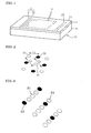
- Figure 1 is a perspective view schematically showing an embodiment of the present invention.
- Figure 2 is an enlarged view of part of Figure 1 showing that the distance between spot centers (spot pitch) of the same reagent (L2) is greater than the distance between spot centers (spot pitch) of the two different reagents (L1).
- Figure 3 is a diagram schematically showing an embodiment of the present invention with shields disposed between the reagent spots on the surface and inside of the support.
- Figure 4 is a diagram schematically showing that the shields are linear.
- the analytical test piece 10 of this embodiment has a support 1 and, reagent spots 2, which are aligned on the surface 11 of the support 1 or on the surface 11 and the inside of the support 1 in a specified spot alignment pattern (a spot pitch).
- An analyte-containing sample 3 introduced onto the surface 11 of the support 1 comes in contact with and reacts with the reagent spots 2 aligned on the surface 11 of the support 1 or on the surface 11 and inside of the support 1 and produces a detectable substance (a signal substance) or exhibits a detectable property (a signal property).
- reagent spots 21 and 22 in Figure 1 There are two or more types of reagent spots (indicated as 21 and 22 in Figure 1) in the reagent spots 2, with each reagent spot containing an ingredient which exhibits a given function when mixed with the other ingredients.
- the sample 3 introduced to the surface 11 of the support 1 comes in contact with the two or more types of reagent spots 21 and 22, causes the reagent spots 21 and 22 to mix together, and reacts with the mixed reagent spots, thereby forming a signal substance or exhibiting a signal property.
- the analytical reliability, analytical sensitivity (analytical precision), and storage stability can be increased in this manner.
- Any material having a surface 11 can be used as the support 1 in this embodiment without any specific limitations.
- a porous material can be given as a preferred example.
- a hydrophilic porous material is particularly preferable. Celluloses, polyether sulfones, acrylic polymers, and the like having pores with a pore diameter from 0.2 ⁇ m to several ⁇ m are preferably used.
- the use of a porous material as the support 1 increases the amount of the content in the solution in the reagent spots 2 (21, 22) to be permeated into the support 1, which results in improved analytical sensitivity.
- any compounds that can be mixed with each other by introducing the sample 3 and produce a signal substance or exhibit a signal property by being brought into contact with and reacting with the analyte in the sample 3 may be used without any specific limitations.
- the activity of lactate dehydrogenase as an analyte is measured (i.e.
- a solution containing lactate dehydrogenase when used as an analyte), a solution containing lactic acid as a substrate, NAD (nicotinamide adenine dinucleotide) as a coenzyme, 1-methoxy PMS (phenazine methosulfate) as an electron carrier, and NTB (nitrotetrazolium blue) as a tetrazolium reagent is used as the solution for one reagent spot 21, and a buffer solution such as a phosphate buffer, Tris hydrochloric acid (Tris-HCl) buffer, or the like is used as the solution for another reagent spot 22.
- Tris-HCl Tris hydrochloric acid
- At least one of the solutions for the reagent spots 21 and 22 preferably contains a coloring substance.
- the coloring substance ensures production of a manifest signal substance or exhibition of a manifest signal property.
- reducing reagents such as a Formazan reagent and oxidizing reagents such as a 4-aminoantipyrine solution, a phenol solution, and the like can be mentioned.
- At least one of the solutions for the reagent spots 2 preferably contains a fluorescent substance.
- the fluorescent substance ensures a fluorescent inspection of contact of the reagent spots 21 and 22 with each other which is difficult to confirm with naked eye inspection and thereby ensures stable inspection quality.
- a substance that can emit fluorescence without impairing inspection performance of the reagent spots 21 and 22, for example, food colors of green, yellow, blue, and the like can be given.
- At least one of the solutions for the reagent spots 2 preferably contains a water-soluble polymer.
- the water-soluble polymer prevents the components of the reagent spots 21 and 22 from leaking out due to moisture in the atmosphere and ensures stable storage of the reagent spots 21 and 22 for a long period of time without impairing the properties of the reagents.
- water-soluble shields 24 are preferably located in the spaces where no reagent spots 21 and 22 are disposed (spaces between reagent spots) on the surface 11 of the support 1 or on the surface 11 and inside of the support 1 to ensure long-term storage stability.
- the water-soluble shield 24 is preferably located at a point from which the distance to a reagent spot 21 and a reagent spot 22 is the smallest.
- a shield 24 with any dimension that does not contact the reagent spots 21 and 22 may be used.
- the shield of any shape which can be located between the reagent spots 21 and 22 without coming into contact with them can be used without any specific limitations.
- a straight line shield shown in Figure 4 is preferable. However, a curved shield is also acceptable.
- a water-soluble polymer can maximize the region of the reagent spots 21 and 22 and increase the sensitivity, because the water-soluble polymer does not excessively expand on the surface and inside of the support due to the comparatively high viscosity.
- sugar polymers e.g. pullulan
- polypropylene glycol polyethylene glycol
- sodium carboxycellulose polyvinyl alcohol
- dextran partial hydrolyzate of starch, and the like
- the method for forming a shield 24 may be appropriately selected according to the degree of hydrophilicity of the support 1.
- the inkjet method is preferably used to ensure permeation of the shield material in the thickness direction.
- the inkjet method is more preferable due to the capability of increasing the sensitivity by producing a minute pattern of the shields 24 and enlarging the area in which the reagent spots 21 and 22 are formed.
- the reagent spots 2 (reagent spots 21 and 22) aligned in at least one area on the surface 11 of the support 1 or on the surface 11 and inside of the support 1 are preferably a different type from the reagent spots 2 (reagent spots 21 and 22) aligned in other areas. This manner of alignment of the reagent spots 2 enables inspection of two or more items using a small amount of sample.
- the reagent spots 2 (reagent spots 21 and 22) aligned in at least one area on the surface 11 of the support 1 or on the surface 11 and inside of the support 1 preferably have a concentration different from the reagent spots 2 (reagent spots 21 and 22) aligned in other areas. This manner of alignment of the reagent spots 2 enables quantitative analysis using one piece of analytical test specimen.
- the reagent spots 2 are aligned not only on the surface, but also inside the support 1, the reagent spots 2 (reagent spots 21 and 22) are preferably aligned so that those on the surface 11 of the support 1 exhibit the highest reactivity with the samples. This manner of alignment of the reagent spots 2 enables exhibition of a clear signal property with a small amount of sample and ensures unfailimg inspection.
- the reagent spots 2 are aligned not only on the surface, but also inside the support 1, the reagent spots 2 (reagent spots 21 and 22) are preferably aligned so that those on the surface 11 of the support 1 have the highest concentration. This manner of alignment of the reagent spots 2 enables exhibition of clear signal property with a small amount of sample and ensures unfailing inspection.
- a surfactant is preferably provided in the spaces where no reagent spots 2 (reagent spots 21 and 22) are aligned (between reagent spots) on the surface 11 of the support 1 or on the surface 11 and inside of the support 1.
- the surfactant can reduce the time of contact and reaction of the reagent spots 21 and 22 with the sample 3 and accelerate dispersion of signal substances.
- any of anionic surfactants, cationic surfactants, and nonionic surfactants may be appropriately selected according to the use conditions.
- anionic surfactants such as alkylaryl sulfonate and alkylbenzene sulfonate, cationic surfactants such as alkyltrimethyl ammonium and alkyl pyridinium, nonionic surfactants such as polyoxyethylene fatty acid ester, polyoxyethylene alkyl phenyl, and the like can be given.
- a foaming agent is preferably provided in the spaces where no reagent spots 2 (reagent spots 21 and 22) are aligned (between reagent spots) on the surface 11 of the support 1 or on the surface 11 and inside of the support 1.
- the foaming agent reduces the time for the contact and reaction of the reagent spots 21 and 22 with the sample 3 by promoting mixing of the reagent spot 21 and reagent spot 22.
- KHCO 3 potassium hydrogencarbonate
- NaHCO 3 sodium hydrogencarbonate
- the supporting body 4 ensures easy operation and easy alignment of the reagent spots 2 (reagent spots 21 and 22).
- the supporting body 4 may have any configuration that can surely support the support 1 without specific limitation.
- a metal, ceramic, glass, resin, and the like can be mentioned.
- resins are preferable from the viewpoint of the low cost and stability to solutions.
- PET resins, acrylic resins, vinyl chloride resins, and the like can be given.
- the cross-section of the reagent spots 21 and 22 cut along a specified plane parallel to the surface 11 of the support 1, for example, a plane at a 1/2 depth from the surface 11 of the support 1, is preferably oval or elliptical, or has the shape of a race track.
- Such a cross-sectional configuration can reduce the time for the contact and reaction of the reagent spots 21 and 22 with the sample 3.
- the distance between spot centers (spot pitch) of the same reagent is preferably greater than the distance between spot centers (spot pitch) of the two different reagents ( Figure 2, a reagent spot 21 and a reagent spot 22) (L1).
- Such an arrangement ensures mixing of the reagent spots 21 and 22 when the sample 3 is introduced.
- the diameter of the reagent spots 21 and 22 is preferably 0.5 mm or less, and more preferably 0.05 to 0.25 mm, and the distance (spot pitch) between the center of the different reagent spots (a reagent spot 21 and a reagent spot 22) (L1) is preferably 0.6 mm or less, and more preferably 0.1 to 0.4 mm, as shown in Figure 2, the time for the contact and reaction of the reagent spots 21 and 22 with the sample 3 can be reduced and dispersion of signal substances is promoted and, at the same time, the sample 3, the reagent spot 21 and reagent spot 22 can be homogeneously mixed, whereby production of the signal substances and exhibition of the signal property can be ensured.
- the above reagent spot diameter and spot pitch are particularly preferable when the inspection and analysis rely upon the amount of luminescence as a signal property, because a luminous intensity can be easily identified by naked eye observation.
- the alignment ratio (A) (S1/S2) satisfy the inequality 0.01 ⁇ (A) ⁇ 0.814, wherein S 1 indicates the total cross-sectional areas of the reagent spots 21 and 22 in a specified plane parallel to the surface 11 of the support 1, for example, a plane at a 1/2 depth from the surface 11 of the support 1, and S2 is the area of the surface 11 of the support 1. If the alignment ratio (A) is 0.01 or less, it is difficult to reduce the time for the contact and reaction of the reagent spots 21 and 22 with the sample 3; if 0.814 or more, long term stability may be impaired. Taking the long term reliability into consideration, a more preferable range for the alignment ratio (A) is 0.09 ⁇ (A) ⁇ 0.35.
- a spot pitch which is the aligning pattern of the reagent spots 21 and 22 on the surface 11 of the support 1 or on the surface 11 and inside of the support 1, in a certain area differs from the spot pitch in other areas. Since the reagent spots 21 and 22 in the area with a short spot pitch deteriorates due to absorption of water faster than in other areas, it is easy to determine quantitatively deterioration of the reagent spots 21 and 22 by differentiating the spot pitch in a certain area from the other areas. In addition, differentiating the spot pitch enlarges the analytical (measuring) area.
- each of the confirmation reagent spots 23 preferably contains the above-described different solution. In this manner, production of a signal substance and exhibition of a signal property can be promptly confirmed beforehand, whereby the reliability of the test piece can be increased.
- the amount of the solution (spot amount) in the reagent spots 21 and 22 in at least one area on the surface 11 of the support 1 or on the surface 11 and inside of the support 1 preferably differs from the spot amount in other areas, for example, the spot amount in the central area to which the sample 3 is introduced is larger than the spot amount of other areas. In this manner, an optimum spot amount range for the sample 3 can be expanded, that is, the analytical sensitivity can be easily altered, so that quantitative analysis is possible using one sheet of analytical test piece.
- the needle method of forming a reagent spot in which a needle is caused to come in contact with a flat plane of the support to transfer the solution to the flat plane, can also be used.
- needle tips There are various types of needle tips. Needles having any type of needle tip, such as a solid needle type with no grooves at the tip, a quill needle type with a fountain pen groove at the tip, a needle-and-ring type with a ring to store a solution of which the membrane is pierced by a needle to cause the solution to pour out, and the like can be used. Of these, the quill needle type is preferable.
- the method for preparing the analytical test piece 10 of this embodiment comprises forming reagent spots 2 by aligning prescribed solutions on the surface 11 of the support 1 or on the surface 11 and inside of the support 1 in a prescribed spot alignment pattern (a spot pitch), causing an analyte-containing sample 3 introduced onto the surface 11 of the support 1 to come in contact with and react with the reagent spots 2, thereby producing a detectable substance (a signal substance) or exhibiting a detectable property (a signal property), wherein two or more types of reagent spots (shown by 21 and 22 in Figure 1), each containing a solution different from the solution in the other types of spots and each exhibiting a given function by being mixed together with the other types of spots when brought into contact with a sample 3 to be introduced, are formed on the surface 11 of the support 1 or on the surface 11 and the inside of the support 1, by means of the inkjet method described later, and the sample 3 introduced onto the surface 11 of the support 1 comes in contact with the reagent spots 21 and 22 formed on the surface 11
- the inkjet method can accurately and densely locate spots, whereby a precise amount of reagent can be charged into each reagent spot. Consequently, not only the sensitivity distribution in the analytical test piece can be minimized, which results in increased analytical reliability, but also uniform analytical quality can be ensured even if a large analytical test piece is used, which gives rise to increased production efficiency.
- a high sensitive analytical test piece capable of analyzing a very small amount of samples can be obtained by densely locating the reagent spots. Furthermore, since a precise amount of reagent can be charged into the reagent spots, the storage stability of the analytical test piece can be improved.
- an apparatus comprising a fluid channel substrate in which a fluid channel is formed, an actuator installed in the fluid channel substrate having a function of changing the volume of a cavity as a pressurizing chamber, a nozzle substrate attached to the bottom of the fluid channel substrate with nozzles formed therein, and a liquid receiver installed on the rear top of the fluid channel substrate can be given, for example.
- the apparatus disclosed in Japanese Patent Application Laid-open No. 2003-75305 for example, can be preferably used.
- any material having a surface 11 can be used as the support 1 in this embodiment without any specific limitations.
- a porous material can be given as a preferred example.
- a hydrophilic porous material is particularly preferable. Celluloses, polyether sulfones, acrylic polymers, and the like having pores with a pore diameter from 0.2 ⁇ m to several ⁇ m are preferably used.
- the use of a porous material as the support 1 increases the amount of the solution in the obtained reagent spots 2 (21, 22) to permeate the support 1, which results in improved analytical sensitivity. Since the inkjet method can supply reagents to the support without contact, an analytical test piece with no surface unevenness can be obtained even if a porous material is used as the support.
- any compounds that can be mixed with each other by introducing the sample 3 and produce a signal substance or exhibit a signal property by being brought into contact with and reacting with the analyte in the sample 3 may be used without any specific limitations.
- the activity of lactate dehydrogenase as an analyte is measured (i.e.
- a solution containing lactate dehydrogenase when used as an analyte), a solution containing lactic acid as a substrate, NAD (nicotinamide adenine dinucleotide) as a coenzyme, 1-methoxy PMS (phenazine methosulfate) as an electron carrier, and NTB (nitrotetrazolium blue) as a tetrazolium reagent is used as the solution for one reagent spot 21, and a buffer solution such as a phosphate buffer, Tris hydrochloric acid (Tris-HCl) buffer, or the like is used as the solution for another reagent spot 22.
- Tris-HCl Tris hydrochloric acid
- At least one of the solutions for the reagent spots 21 and 22 preferably contains a coloring substance.
- An analytical test piece 10 capable of producing a manifest signal substance or exhibiting a manifest signal property can be obtained by using a coloring substance.
- the solution containing such a coloring substance reducing reagents such as a Formazan reagent and oxidizing reagents such as a 4-aminoantipyrine solution, a phenol solution, and the like can be mentioned.
- the inkjet method can be used for supplying a solution containing a coloring substance. The inkjet method can supply a precise quantity of a coloring substance and produce a high quality analytical test piece.
- Two or more solutions in the reagent spots 21 and 22 preferably contains a fluorescent substance.
- the fluorescent substance ensures a fluorescent inspection of contact of the reagent spots 21 and 22 with each other which is difficult to confirm with naked eye inspection and thereby ensures stable inspection quality.
- a substance that can emit fluorescence without impairing inspection performance of the reagent spots 21 and 22, for example, food colors of green, yellow, blue, and the like can be given.
- the inkjet method can be used for supplying a solution containing a fluorescent substance.
- the inkjet method can supply a precise quantity of a fluorescent substance and produce a high quality analytical test piece.
- Adding a water-soluble polymer to at least one of the solutions is preferable from the viewpoint of ensuring long term storage stability.
- the water-soluble polymer prevents the components of the reagent spots 21 and 22 from escaping to the atmosphere due to moisture in the atmosphere and ensures stable storage of the reagent spots 21 and 22 for a long period of time without impairing the properties of the reagents.
- water-soluble shields 24 are preferably located in the spaces where no reagent spots 21 and 22 are disposed (spaces between reagent spots) on the surface 11 of the support 1 or on the surface 11 and inside of the support 1 to ensure stable storage of the reagent spots 21 and 22 for a long period of time.
- the shield 24 is preferably located at a point from which the distance to a reagent spot 21 and a reagent spot 22 is the smallest.
- a shield 24 with any dimension that does not contact the reagent spots 21 and 22 may be used.
- a shield of any shape which can be located between the reagent spots 21 and 22 without coming into contact with them can be used without any specific limitations.
- a straight line shield shown in Figure 4 is preferable. However, a curved shield is also acceptable.
- a water-soluble polymer can maximize the region of the reagent spots 21 and 22 and increase the sensitivity, because the water-soluble polymer does not excessively expand on the surface and inside of the support due to the comparatively high viscosity.
- sugar polymers e.g. pullulan
- polypropylene glycol polyethylene glycol
- sodium carboxycellulose polyvinyl alcohol
- dextran partial hydrolyzate of starch, and the like
- the method for forming the shield 24 may be appropriately selected according to the degree of hydrophilicity of the support 1.
- the inkjet method is preferably used to ensure permeation of the shield material in the thickness direction.
- the inkjet method is more preferable due to the capability of increasing the sensitivity by producing a minute pattern of the shield 24 and enlarging the area in which the reagent spots 21 and 22 are formed.
- the cross-section of the reagent spots 21 and 22 cut along a specified plane parallel to the surface 11 of the support 1, for example, a plane at a 1/2 depth from the surface 11 of the support 1, is preferably oval or elliptical, or has the shape of a race track.
- This configuration makes it possible for the analytical test piece to reduce the time for the contact and reaction of the reagent spots 21 and 22 with the sample 3.
- the above-described configuration can be easily formed by using the inkjet method.
- the distance between spot centers (spot pitch) of the same reagent is preferably greater than the distance between spot centers (spot pitch) of the two different reagents ( Figure 2, a reagent spot 21 and a reagent spot 22) (L1).
- Such an arrangement ensures mixing of the reagent spots 21 and 22 when the sample 3 is introduced.
- the diameter of the reagent spots 21 and 22 is preferably 0.5 mm or less, and more preferably 0.05 to 0.25 mm, and the distance (spot pitch) between the center of the different reagent spots (a reagent spot 21 and a reagent spot 22) (L1) is preferably 0.6 mm or less, and more preferably 0.1 to 0.4 mm, as shown in Figure 2, the analytical test piece 10 which can reduce the time for the contact and reaction of the reagent spots 21 and 22 with the sample 3 and also can ensure homogeneous mixing of the sample 3, the reagent spot 21 and reagent spot 22, thereby ensuring production of the signal substances and exhibition of the signal property, can be obtained.
- the above reagent spot diameter and spot pitch are particularly preferable when the inspection and analysis rely upon the amount of luminescence as a signal property, because a luminous intensity can be easily identified by naked eye observation.
- the alignment ratio (A) (S1/S2) satisfy the inequality 0.01 ⁇ (A) ⁇ 0.814, wherein S1 indicates the total cross-sectional areas of the reagent spots 21 and 22 in a specified plane parallel to the surface 11 of the support 1, for example, a plane at a 1/2 depth from the surface 11 of the support 1, and S2 is the area of the surface 11 of the support 1.
- the alignment ratio (A) is 0.01 or less, it is difficult to obtain an analytical test piece 10 which can reduce the time for the contact and reaction of the reagent spots 21 and 22 with the sample 3; if 0.814 or more, long term stability of the analytical test piece 10 may be impaired. Taking the long term reliability of the analytical test piece 10 into consideration, a more preferable range for the alignment ratio (A) is 0.09 ⁇ (A) ⁇ 0.35.
- the above spot pitch, diameter, and cross-sectional area alignment ratio can be efficiently achieved by using the inkjet method which can supply a precise amount of reagent without contact.
- a spot pitch which is the aligning pattern of the reagent spots 21 and 22 on the surface 11 of the support 1 or on the surface 11 and inside of the support 1, in a certain area differs from the spot pitch in other areas. Since the reagent spots 21 and 22 in the area with a short spot pitch deteriorates due to absorption of water faster than in other areas, it is possible to obtain an analytical test piece 10 which can quantitatively determine deterioration of the reagent spots 21 and 22 with ease by differentiating the spot pitch in a certain area from the other area. In addition, differentiating the spot pitch can produce an analytical test piece 10 with an enlarged analytical (measuring) area. In addition, this manner of alignment of the reagent spots 2 enables quantitative analysis using one piece of analytical test specimen.
- the confirmation reagent spots 23 for identifying proper alignment may be located within the ultimate configuration of analytical test piece 10 or may be located on the support 1 before the ultimate configuration is formed (outside the analytical test piece 10). Providing such additional reagent spots makes it possible to confirm mixing conditions of a reagent spot 21 and a reagent spot 22, for example, before aligning the reagent spots 21 and 22, thereby increasing the reliability of the analytical test piece 10.
- each of the confirmation reagent spots 23 preferably contains the above-described different solution. In this manner, production of a signal substance and exhibition of a signal property can be promptly confirmed beforehand, whereby the reliability of the test piece can be increased. If the inkjet method is used for forming the confirmation reagent spots 23, the same spots as the reagent spots 21 and 22 in the analytical test piece 10 can be easily formed, whereby precise inspection can be ensured.
- the reagent spots 21 and 22 aligned in at least one area on the surface 11 of the support 1 or on the surface 11 and inside of the support 1 are preferably a different type from the reagent spots 21 and 22 aligned in other areas.
- This manner of alignment of the reagent spots 2 enables inspection of two or more items using a small amount of sample.
- reagent spots can be formed at a high density by using the inkjet method, it is possible to prepare chips capable of inspecting different types of substances without enlarging the size of the chips.
- the reagent spots 21 and 22 aligned in at least one area on the surface 11 of the support 1 or on the surface 11 and inside of the support 1 preferably have a different concentration from the reagent spots 21 and 22 aligned in other areas. Since reagent spots can be formed at a high density by using the inkjet method, it is possible to change the concentration even when the area is small. This manner of alignment of the reagent spots 2 enables quantitative analysis using one piece of analytical test specimen.
- the reagent spots 21 and 22 are aligned not only on the surface, but also inside the support 1, the reagent spots 21 and 22 are preferably aligned so that those on the surface 11 of the support 1 exhibit the highest reactivity with samples.
- This manner of alignment of the reagent spots 2 enables exhibition of a clear signal property with a small amount of sample and ensures unfailing inspection.
- the reagent spots can be aligned so that those on the surface 11 exhibit the highest reactivity with samples.
- such reagent alignment is efficiently achieved by providing a solution with a specified concentration injected in a certain area of the support 1, and then injecting the solution with a larger concentration in the same area using the same apparatus with a longer drying time at the nozzle plane that is , for example, with a longer interval time between each injection.
- the reagent spots 21 and 22 are aligned not only on the surface, but also inside the support 1, the reagent spots 21 and 22 are preferably aligned so that those on the surface of the support 1 have a highest concentration. This manner of alignment of the reagent spots 2 enables exhibition of a clear signal property with a small amount of sample and ensures unfailing inspection.
- a surfactant (not shown) is preferably provided in the spaces where no reagent spots 21 and 22 are aligned (between the reagent spots 21 and 22) on the surface 11 of the support 1 or on the surface 11 and inside of the support 1.
- the use of the surfactant can produce an analytical test piece 10 which can reduce the time for the contact and reaction of the reagent spots 21 and 22 with the sample 3 and accelerate dispersion of signal substances.
- any of anionic surfactants, cationic surfactants, and nonionic surfactants may be appropriately selected according to the use conditions.
- anionic surfactants such as alkylaryl sulfonate and alkylbenzene sulfonate, cationic surfactants such as alkyltrimethyl ammonium and alkyl pyridinium, nonionic surfactants such as polyoxyethylene fatty acid ester, polyoxyethylene alkyl phenyl, and the like can be given.
- a foaming agent (not shown) is preferably provided in the spaces where no reagent spots 21 and 22 are aligned (between the reagent spots 21 and 22) on the surface 11 of the support 1 or on the surface 11 and inside of the support 1.
- the use of the foaming agent can provide an analytical test piece 10 which can reduce the time for the contact and reaction of the reagent spots 21 and 22 with the sample 3 by promoting mixing of the reagent spot 21 and reagent spot 22.
- a foaming agent separately disposed potassium hydrogencarbonate (KHCO 3 ) or sodium hydrogencarbonate (NaHCO 3 ) and an organic acid can be given, for example. Since the inkjet method can uniformly supply a very small amount of surfactant and foaming agent, a large number of analytical test pieces 10 with uniform quality can be prepared.
- the supporting body 4 ensures easy operation and easy alignment of the reagent spots.
- the supporting body 4 may have any configuration that can surely support the support 1 without specific limitation.
- a metal, ceramic, glass, resin, and the like can be mentioned.
- resins are preferable from the viewpoint of the low cost and stability to solutions.
- PET resins, acrylic resins, vinyl chloride resins, and the like can be given.
- a great many very small independent droplets can be preferably produced by using the inkjet method. Since such a great many very small independent droplets are concentrated before reaching the support 1, it is possible to supply the reagent spots 21 and 22 with a large spot amount (the amount of liquid drops forming the reagent spots 21 and 22) without enlarging the spot diameter of the reagent spots 21 and 22, whereby analytical sensitivity of the resulting analytical test piece 10 can be further increased.
- the amount of liquid drops forming the reagent spots 21 and 22 is preferably 0.1 ⁇ l or less, and more preferably 0.002 to 0.02 ⁇ l. If more than 0.1 ⁇ l, the liquid drops of the solution expand on the support 1 and unnecessarily enlarge the spot diameter, resulting in a analytical test piece 10 which possibly takes a long time to cause the reagent spots 21 and 22 to come into contact and react with the sample 3.
- the amount of the solution (spot amount) in the reagent spots 21 and 22 in at least one area on the surface 11 of the support 1 preferably differs from the spot amount in other areas, for example, the spot amount in the central area to which the sample 3 is introduced is larger than the spot amount of other areas.
- an optimum spot amount range for the sample 3 can be expanded, that is, the analytical sensitivity of the resulting analytical test piece 10 can be easily altered, so that quantitative analysis is possible using one sheet of the analytical test piece 10.
- even small chips can be easily formed by using the inkjet method.
- Each of the reagent spots 21 and 22 is preferably formed by injecting droplets of the solution two or more times. In this manner, the spot amount can be increased and thereby the sensitivity of the resulting analytical test piece 10 can be increased without unnecessarily enlarging the spot diameter.
- the liquid drops of the solution are injected onto the support 1 which is maintained preferably at 40°C or less, more preferably 15 to 30°C to ensure quick drying of the liquid drops after forming the reagent spots 21 and 22, while suppressing expansion of the reagent spots 21 and 22.
- the spot amount can be increased without unnecessarily enlarging the spot diameter and the sensitivity of the resulting analytical test piece 10 can be increased.
- the liquid drops of the solution are preferably injected while the back of the support 1 is separated from the supporting body 4. Because this manner of forming the reagent spots 21 and 22 can suppress undue expansion of the reagent spots 21 and 22 on the back of the support 1 and can prevent unnecessary mixing of the liquid drops, the sensitivity of the resulting analytical test piece 10 can be increased.
- the analytical test piece 10 prepared by any of the above-described methods is provided with a support 1 with a surface 11 and reagent spots 2 consisting of reagent spots 21 and 22 which are aligned on the surface 11 of the support 1 or on the surface 11 and the inside of the support 1 in a specified spot alignment pattern (a spot pitch), the reagent spots being formed by the inkjet method by injecting liquid drops of two or more different solutions, each exhibiting a given function upon being mixed together, wherein an introduced analyte-containing sample 3 comes in contact with the reagent spots 21 and 22, causes the reagent spots 21 and 22 to mix together, and reacts with the mixed reagent spots, thereby forming a detectable substance or detectable property (a signal substance or signal property).
- a spot pitch a specified spot alignment pattern
- the analytical test piece is useful as an inspection chip for inspecting and analyzing samples 3 containing an analyte (e.g. a body fluid, particularly urine, blood, etc. of humans and animals) introduced onto the surface 11 of the support 1 and excelling in analysis reliability, analytical sensitivity (analytical precision), and storage stability.
- an analyte e.g. a body fluid, particularly urine, blood, etc. of humans and animals
- Example 1 to 2 Sample analytical test pieces were prepared by using a needle method for forming reagent spots according to the following procedure and were subjected to evaluation of long term stability and the other properties.
- a first reagent a first solution containing lactic acid, NAD (nicotinamideadeninedinucleotide), 1-methoxy PMS (phenazine methosulfate), and NTB (nitrotetrazolium blue) was used.
- a phosphate buffer (a second solution) was used. Cow milk was used as an analyte sample.
- As supports 5 mm ⁇ 5 mm boards with a thickness of 0.16 mm made of hydrophilic cellulose mixture ester with pore size of 0.8 ⁇ m were used.
- the first solution and the second solution were carried on the needle, which was brought into contact with the supports to dispense the first and second solutions onto the supports to form fist and second reagent spots.
- the first and second solutions in approximate amounts of 0.01 ⁇ l and 0.06 ⁇ l were respectively dispensed to each of the first and second reagent spots to form the first and second reagent spots with approximate pitches of 0.6 mm and 1.5 mm, and approximate diameters of 0.3 mm and 1.2 mm. Properties of the resulting first and second samples were evaluated. The results are shown in Table 1.
- Comparative Example 1 A comparative analytical test piece sample was prepared using the liquid impregnation method as the method for forming reagent spots. Properties of the resulting sample were evaluated. Specifically, the same first and second reagents as used in Example 1 were put into beakers. Then, the same support material as used in Example 1 was put into the beaker containing the first reagent to impregnate the support with the first reagent. After drying at 30°C, the support material was put into the beaker containing the second reagent to impregnate the support with the second reagent. The resulting support material was dried at 30°C to obtain the comparative sample impregnated with the first and second reagents. Properties of the obtained comparative sample were evaluated. The results are shown in Table 1.
- Example 2 Pitch (mm) - 0.6 1.5 (Reagent spot forming method) (Impregnation method) (Needle method) (Needle method) Diameter (mm) (Reagent spot) - 0.3 1.2 Spot amount ( ⁇ l) - 0.01 0.06 Stability 1 day after preparation Good Good Good 7 days after preparation Good Good Good . 30 day after preparation Bad Good Good Unevenness in spots (Sensitivity) None (Good) None (Good) None (Good) Unevenness in chips None None None None None None None None (Good)
- the reagent spots formed by aligning specific solutions (the first and second solutions in Examples 1 and 2) on the surface and inside of the support in a prescribed spot alignment pattern (a spot pitch) can be brought into contact and react with an analyte-containing sample introduced onto the surface of the support, and produce a detectable signal. It was further confirmed that an analytical test piece excelling in long term stability can be obtained. Although two reagent solutions were used in Examples 1 and 2, taking stability into consideration, three or four types of reagent solutions may be used for forming the reagent spots.
- Examples 3 to 5 Samples were prepared by using the inkjet method for forming reagent spots according to the following procedure and subjected to evaluation of long term stability and other properties.
- a first reagent a first solution containing lactic acid, NAD (nicotinamideadeninedinucleotide), 1-methoxy PMS (phenazine methosulfate), and NTB (nitrotetrazolium blue) was used.
- a phosphate buffer a second solution
- Cow milk was used as an analyte sample.
- First and second reagent spots were prepared using the first and second solutions, the supports, and the injecting unit described in Japanese Patent Application Laid-open No. 2003-75305.
- the first and second solutions in approximate amounts of 0.003 ⁇ l, 0.01 ⁇ l, and 0.06 ⁇ l were respectively dispensed to each of the first and second reagent spots to form the first and second reagent spots with approximate pitches of 0.3 mm, 0.6 mm, and 1.5 mm, and approximate diameters of 0.15 mm, 0.3 mm and 1.2 mm.
- Properties of the resulting first to third samples (Examples 3 to 5) were evaluated. The results are shown in Table 2.
- a first comparative sample (Comparative Example 2) was prepared using the liquid impregnation method as the method for forming reagent spots. Properties of the resulting sample were evaluated. Specifically, the same first and second reagents as used in Example 3 were put into beakers. Then, the same support material as used in Example 3 was put into the beaker containing the first reagent to impregnate the support with the first reagent. After drying at 30°C, the support material was put into the beaker containing the second reagent to impregnate the support with the second reagent. The resulting support material is dried at 30°C to obtain a comparative sample impregnated with the first and second reagents. Properties of the obtained first comparative sample (Comparative Example 2) were evaluated. The results are shown in Table 2.
- the second comparative sample (Comparative Example 3) was prepared using the needle method of forming reagent spots, in which the first solution and the second solution were carried on the needle, which was brought into contact with the support to dispense the first and second solutions onto the support to form first and second reagent spots.
- a quill needle of the type with a groove like the groove in a fountain pen was used as the needle.
- Table 2 The results are shown in Table 2.
- the first and second solutions in an approximate amount of 0.003 ⁇ l were dispensed to each of the first and second reagent spots to form the first and second reagent spots with an approximate pitch of 0.3 mm, and approximate diameter of 0.15 mm.
- Properties of the resulting second comparative sample (Comparative Example 3) were evaluated. The results are shown in Table 2.
- Example 5 the first and second reagents exhibited unevenness in the concentration in the central area and the neighborhood of the reagent spots.
- the unevenness presented no problem in practice.
- An analyte sample was dropped onto each of the above analytical test piece samples to measure the reflectance in the same manner as above to confirm the sensitivity.
- the sensitivity was rated as "Good” only in the case in which all samples after dropping the analyte samples exhibited a reflectance decrease of 20% or more from the reflectance before dropping the analyte samples.
- the samples were observed by the naked eye for inspection of unevenness in spots and unevenness in a 5 mm ⁇ 5 mm square.
- Example 6 and 7 Fourth and fifth analyte samples for Examples 6 and 7, respectively, were prepared using alkaline phophataze instead of cow's milk (lactate dehydrogenase). Analytical test piece samples were prepared by using the inkjet method for forming reagent spots according to the following procedure and subjected to evaluation of long term stability and the other properties.
- the first reagent a mixture of 18.94 mM disodium p-nitrophenyl phosphate and 0.505 mM magnesium chloride (hexahydrate) (a first solution) was used and as the second reagent, a mixture of 5.05 mM 2-ethylaminoethanol and 0.505 mM magnesium chloride (hexahydrate) (a second solution) was used.
- Alkaline phophataze was used as an analyte sample.
- supports 5 mm ⁇ 5 mm boards with a thickness of 0.16 mm made of hydrophilic cellulose mixture ester with pore size of 0.8 ⁇ m were used.
- First and second reagent spots were prepared using the first and second solutions, the supports, and the injecting unit described in Japanese Patent Application Laid-open No. 2003-75305.
- the first and second solutions in approximate amounts of 0.01 ⁇ l and 0.06 ⁇ l were respectively dispensed to each of the first and second reagent spots to form the first and second reagent spots with approximate pitches of 0.6 mm and 1.5 mm, and approximate diameters of 0.3 mm and 1.2 mm.
- Properties of the resulting fourth and fifth samples (Examples 6 and 7) were evaluated. The results are shown in Table 3.
- Example 4 A third comparative analytical test piece sample (Comparative Example 4) was prepared using the liquid impregnation method as the method for forming reagent spots. Properties of the resulting sample were evaluated. The results are shown in Table 3. Specifically, the same support as used in Example 6 was impregnated with the same first and second reagents as used in Example 6 (a mixture of 1.01 mM 2-ethylaminoethanol, 75.75 mM disodium p-nitrophenyl phosphate, and 0.505 mM magnesium chloride (hexahydrate) as first and second solutions) in the same manner as in Comparative Example 2 to obtain a third comparative sample (Comparative Example 4). Properties of the sample were evaluated. The results are shown in Table 3.
- Example 7 The case in which the relative value decreased 10% or more from the initial value (absorbance immediately after preparation) in all samples was rated as "Bad” and the case in which all the samples exhibited a relative value decrease of less than 10% was rated as “Good”.
- the first and second reagents exhibited unevenness in the concentration in the central area and the neighborhood of the reagent spots. However, the unevenness presented no problem in practice.
- An analyte sample was dropped onto each of the above analytical test piece samples to measure the reflectance in the same manner as above to confirm the sensitivity. The sensitivity was rated as "Good” only in the case in which all samples after dropping the analyte samples exhibited a reflectance decrease of 20% or more from the reflectance before dropping the analyte samples.
- the samples were observed by the naked eye for inspection of unevenness in spots and unevenness in a 5 mm ⁇ 5 mm square.
- Example 7 Pitch (mm) - 0.6 1.5 (Reagent spot forming method) (Impregnation) (Inkjet) (Inkjet) Diameter (mm) (Reagent spot) - 0.3 1.2 Spot amount ( ⁇ l) - 0.01 0.06 Stability I day after preparation Good Good Good 100 days after preparation Good Good Good 150 days after preparation Bad Good Good Unevenness in spots (Sensitivity) None (Good) None (Good) None (Good) Unevenness in chips None None None None None None None (Good)
- the reagent spots formed by aligning specific solutions (the first and second solutions in Examples 6 and 7) on the surface and inside of the support in a prescribed spot alignment pattern (a spot pitch) can be brought into contact and react with an analyte-containing sample introduced onto the surface of the support, and produce a detectable signal. It was further confirmed that an analytical test piece excelling in long term stability with various types of solutions can be obtained. Although two reagent solutions were used in Examples 6 and 7, taking stability into consideration, three or four types of reagent solutions may be used for forming the reagent spots.
- the analytical test piece and the method for preparing the same of the present invention are effectively used for inspecting and analyzing samples containing an analyte (e.g. a body fluid, particularly urine, blood, etc. of humans and animals) and for preparing inspection chips and the like for analysis in various fields such as research, drug development, diagnosis, medical treatment, and the like.
- analyte e.g. a body fluid, particularly urine, blood, etc. of humans and animals
- inspection chips and the like for analysis in various fields such as research, drug development, diagnosis, medical treatment, and the like.
Landscapes
- Health & Medical Sciences (AREA)
- Chemical & Material Sciences (AREA)
- Immunology (AREA)
- Life Sciences & Earth Sciences (AREA)
- Hematology (AREA)
- Engineering & Computer Science (AREA)
- Analytical Chemistry (AREA)
- General Health & Medical Sciences (AREA)
- Urology & Nephrology (AREA)
- Chemical Kinetics & Catalysis (AREA)
- Biomedical Technology (AREA)
- Molecular Biology (AREA)
- Cell Biology (AREA)
- Biochemistry (AREA)
- Biotechnology (AREA)
- Clinical Laboratory Science (AREA)
- Food Science & Technology (AREA)
- Medicinal Chemistry (AREA)
- Physics & Mathematics (AREA)
- Microbiology (AREA)
- General Physics & Mathematics (AREA)
- Pathology (AREA)
- Investigating Or Analysing Biological Materials (AREA)
- Investigating Or Analyzing Non-Biological Materials By The Use Of Chemical Means (AREA)
- Investigating Or Analysing Materials By The Use Of Chemical Reactions (AREA)
- Measuring Or Testing Involving Enzymes Or Micro-Organisms (AREA)
Applications Claiming Priority (5)
| Application Number | Priority Date | Filing Date | Title |
|---|---|---|---|
| JP2003180338 | 2003-06-24 | ||
| JP2003180337 | 2003-06-24 | ||
| JP2003345868 | 2003-10-03 | ||
| JP2004122119 | 2004-04-16 | ||
| PCT/JP2004/008886 WO2004113916A1 (fr) | 2003-06-24 | 2004-06-24 | Article pour essai analytique et procede de production correspondant |
Publications (2)
| Publication Number | Publication Date |
|---|---|
| EP1655604A1 true EP1655604A1 (fr) | 2006-05-10 |
| EP1655604A4 EP1655604A4 (fr) | 2007-10-24 |
Family
ID=33545467
Family Applications (1)
| Application Number | Title | Priority Date | Filing Date |
|---|---|---|---|
| EP04746355A Withdrawn EP1655604A4 (fr) | 2003-06-24 | 2004-06-24 | Article pour essai analytique et procede de production correspondant |
Country Status (4)
| Country | Link |
|---|---|
| US (1) | US20060093516A1 (fr) |
| EP (1) | EP1655604A4 (fr) |
| JP (1) | JP4567597B2 (fr) |
| WO (1) | WO2004113916A1 (fr) |
Cited By (1)
| Publication number | Priority date | Publication date | Assignee | Title |
|---|---|---|---|---|
| EP1816479A1 (fr) * | 2004-11-25 | 2007-08-08 | Matsushita Electric Industrial Co., Ltd. | Capteur |
Families Citing this family (1)
| Publication number | Priority date | Publication date | Assignee | Title |
|---|---|---|---|---|
| US20120301370A1 (en) * | 2010-02-15 | 2012-11-29 | Carnegie Mellon University | Apparatus and Process for Producing Patterned, Micron and Nanometer Size Reaction and Mixing Zones for Fluids Deposited on Smooth, Rough and Porous Surfaces and Applications of that Process |
Citations (7)
| Publication number | Priority date | Publication date | Assignee | Title |
|---|---|---|---|---|
| US3770383A (en) * | 1971-04-05 | 1973-11-06 | Akzona Inc | Diagnostic test slide |
| US4216245A (en) * | 1978-07-25 | 1980-08-05 | Miles Laboratories, Inc. | Method of making printed reagent test devices |
| US4639419A (en) * | 1981-10-22 | 1987-01-27 | Meloy Laboratories, Inc. | Immunological color change test involving two differently colored reagent spots |
| US5620863A (en) * | 1989-08-28 | 1997-04-15 | Lifescan, Inc. | Blood glucose strip having reduced side reactions |
| DE19845771A1 (de) * | 1998-09-22 | 2000-03-30 | Felix Levine | Teststreifen zur Glucosebestimmung in Flüssigkeiten |
| US20010041368A1 (en) * | 1987-04-27 | 2001-11-15 | Conopco Inc. | Capillary immunoassay and device therefor comprising mobilizable particulate labelled reagents |
| US6342395B1 (en) * | 1998-04-22 | 2002-01-29 | The Regents Of The University Of California | Compact assay system with digital information |
Family Cites Families (4)
| Publication number | Priority date | Publication date | Assignee | Title |
|---|---|---|---|---|
| NZ509917A (en) * | 1998-07-21 | 2003-05-30 | Pharmexa As | Coating of solid surfaces with activated polyhydroxypolymers |
| SE9802951D0 (sv) * | 1998-09-02 | 1998-09-02 | Amersham Pharm Biotech Ab | Metod för screening samt verktyg att använda i metoden |
| JP3298836B2 (ja) * | 1998-11-12 | 2002-07-08 | アークレイ株式会社 | 検体分析用具 |
| US6656432B1 (en) * | 1999-10-22 | 2003-12-02 | Ngk Insulators, Ltd. | Micropipette and dividedly injectable apparatus |
-
2004
- 2004-06-24 WO PCT/JP2004/008886 patent/WO2004113916A1/fr active Application Filing
- 2004-06-24 JP JP2005507278A patent/JP4567597B2/ja not_active Expired - Fee Related
- 2004-06-24 EP EP04746355A patent/EP1655604A4/fr not_active Withdrawn
-
2005
- 2005-12-15 US US11/303,850 patent/US20060093516A1/en not_active Abandoned
Patent Citations (7)
| Publication number | Priority date | Publication date | Assignee | Title |
|---|---|---|---|---|
| US3770383A (en) * | 1971-04-05 | 1973-11-06 | Akzona Inc | Diagnostic test slide |
| US4216245A (en) * | 1978-07-25 | 1980-08-05 | Miles Laboratories, Inc. | Method of making printed reagent test devices |
| US4639419A (en) * | 1981-10-22 | 1987-01-27 | Meloy Laboratories, Inc. | Immunological color change test involving two differently colored reagent spots |
| US20010041368A1 (en) * | 1987-04-27 | 2001-11-15 | Conopco Inc. | Capillary immunoassay and device therefor comprising mobilizable particulate labelled reagents |
| US5620863A (en) * | 1989-08-28 | 1997-04-15 | Lifescan, Inc. | Blood glucose strip having reduced side reactions |
| US6342395B1 (en) * | 1998-04-22 | 2002-01-29 | The Regents Of The University Of California | Compact assay system with digital information |
| DE19845771A1 (de) * | 1998-09-22 | 2000-03-30 | Felix Levine | Teststreifen zur Glucosebestimmung in Flüssigkeiten |
Non-Patent Citations (2)
| Title |
|---|
| BLANCHARD A P ET AL: "HIGH-DENSITY OLIGONUCLEOTIDE ARRAYS" BIOSENSORS & BIOELECTRONICS, ELSEVIER SCIENCE PUBLISHERS, BARKING, GB, vol. 11, no. 6/7, 26 April 1996 (1996-04-26), pages 687-690, XP002052193 ISSN: 0956-5663 * |
| See also references of WO2004113916A1 * |
Cited By (2)
| Publication number | Priority date | Publication date | Assignee | Title |
|---|---|---|---|---|
| EP1816479A1 (fr) * | 2004-11-25 | 2007-08-08 | Matsushita Electric Industrial Co., Ltd. | Capteur |
| EP1816479A4 (fr) * | 2004-11-25 | 2009-01-21 | Panasonic Corp | Capteur |
Also Published As
| Publication number | Publication date |
|---|---|
| WO2004113916A1 (fr) | 2004-12-29 |
| JPWO2004113916A1 (ja) | 2006-08-03 |
| EP1655604A4 (fr) | 2007-10-24 |
| JP4567597B2 (ja) | 2010-10-20 |
| US20060093516A1 (en) | 2006-05-04 |
Similar Documents
| Publication | Publication Date | Title |
|---|---|---|
| EP1712919B1 (fr) | Instrument analytique a agencement ameliore de section de reactif et procede analytique correspondant | |
| CN1135388C (zh) | 多层试剂检测条及使用其进行检测的方法 | |
| CN102757893B (zh) | 肌酸酐测定用干式试验片及肌酸酐测定法 | |
| CN1423128A (zh) | 溶液干燥系统 | |
| EP0563858B1 (fr) | Procédé de détermination quantitative des microorganismes viables | |
| CN1268929C (zh) | 具有多个反应区的测试片以及使用和制造该测试片的方法 | |
| JP2003534526A (ja) | 少量生物体液試料用診断アッセイ | |
| EP1621887A1 (fr) | Bande de test analytique comprenant une zone de contrôle | |
| CN102759524B (zh) | 钙测定用干式试验片 | |
| DE2850501A1 (de) | Verfahren und vorrichtung zur chemischen spot-test-analyse | |
| EP2794909B1 (fr) | Procédé de détermination d'une concentration d'analyte | |
| DE2532918B2 (de) | Integrales analytisches Element für die Analyse von Flüssigkeiten | |
| JP4584919B2 (ja) | 分析用試験片 | |
| US20060093516A1 (en) | Analytical test piece and process for producing the same | |
| JPH0695954B2 (ja) | クレアチニン又はクレアチンの測定要素及び測定方法 | |
| EP2617834B1 (fr) | Procédé de production de réactif sec, réactif sec et outil d'analyse l'utilisant | |
| EP3578634B1 (fr) | Puce de mesure du niveau de glycémie et ensemble dispositif de mesure du niveau de glycémie | |
| EP0164960B1 (fr) | Elément analytique et son utilisation pour la détermination d'hémoglobine dans le sang entier | |
| EP0374685B1 (fr) | Dispositif de détection enzymatique pour les gaz et les aérosols | |
| US4876207A (en) | Compositions for the detection of high levels of hydrogen peroxide | |
| US20070053790A1 (en) | Analyzing tool being reduced in distance of diffusion of reagent and method for manufacture thereof | |
| JPS60205364A (ja) | 酸素供給層を有する分析用具 | |
| JP2000088857A (ja) | 水性試薬および水性検体用空気遮断剤 | |
| JP2006275716A (ja) | 試験紙 | |
| JP2000055921A (ja) | 尿素定量用試験片 |
Legal Events
| Date | Code | Title | Description |
|---|---|---|---|
| PUAI | Public reference made under article 153(3) epc to a published international application that has entered the european phase |
Free format text: ORIGINAL CODE: 0009012 |
|
| 17P | Request for examination filed |
Effective date: 20060120 |
|
| AK | Designated contracting states |
Kind code of ref document: A1 Designated state(s): DE FR GB |
|
| DAX | Request for extension of the european patent (deleted) | ||
| RBV | Designated contracting states (corrected) |
Designated state(s): DE FR GB |
|
| A4 | Supplementary search report drawn up and despatched |
Effective date: 20070924 |
|
| RIC1 | Information provided on ipc code assigned before grant |
Ipc: B01F 13/00 20060101ALI20070918BHEP Ipc: G01N 33/543 20060101AFI20070918BHEP Ipc: G01N 33/58 20060101ALI20070918BHEP Ipc: B01L 3/00 20060101ALI20070918BHEP Ipc: G01N 33/544 20060101ALI20070918BHEP |
|
| 17Q | First examination report despatched |
Effective date: 20080229 |
|
| STAA | Information on the status of an ep patent application or granted ep patent |
Free format text: STATUS: THE APPLICATION IS DEEMED TO BE WITHDRAWN |
|
| 18D | Application deemed to be withdrawn |
Effective date: 20080711 |