EP1655425B1 - Vorrichtung zum Auftragen eines Zweikomponentenklebers auf eine Bausteinschar eines scharenweise aus Bausteinen aufgebauten Bausteinverbundes - Google Patents
Vorrichtung zum Auftragen eines Zweikomponentenklebers auf eine Bausteinschar eines scharenweise aus Bausteinen aufgebauten Bausteinverbundes Download PDFInfo
- Publication number
- EP1655425B1 EP1655425B1 EP05450177A EP05450177A EP1655425B1 EP 1655425 B1 EP1655425 B1 EP 1655425B1 EP 05450177 A EP05450177 A EP 05450177A EP 05450177 A EP05450177 A EP 05450177A EP 1655425 B1 EP1655425 B1 EP 1655425B1
- Authority
- EP
- European Patent Office
- Prior art keywords
- component adhesive
- building blocks
- course
- adhesive
- distributor head
- Prior art date
- Legal status (The legal status is an assumption and is not a legal conclusion. Google has not performed a legal analysis and makes no representation as to the accuracy of the status listed.)
- Expired - Lifetime
Links
Images
Classifications
-
- B—PERFORMING OPERATIONS; TRANSPORTING
- B05—SPRAYING OR ATOMISING IN GENERAL; APPLYING FLUENT MATERIALS TO SURFACES, IN GENERAL
- B05B—SPRAYING APPARATUS; ATOMISING APPARATUS; NOZZLES
- B05B3/00—Spraying or sprinkling apparatus with moving outlet elements or moving deflecting elements
- B05B3/02—Spraying or sprinkling apparatus with moving outlet elements or moving deflecting elements with rotating elements
- B05B3/10—Spraying or sprinkling apparatus with moving outlet elements or moving deflecting elements with rotating elements discharging over substantially the whole periphery of the rotating member
-
- B—PERFORMING OPERATIONS; TRANSPORTING
- B01—PHYSICAL OR CHEMICAL PROCESSES OR APPARATUS IN GENERAL
- B01F—MIXING, e.g. DISSOLVING, EMULSIFYING OR DISPERSING
- B01F27/00—Mixers with rotary stirring devices in fixed receptacles; Kneaders
- B01F27/27—Mixers with stator-rotor systems, e.g. with intermeshing teeth or cylinders or having orifices
- B01F27/272—Mixers with stator-rotor systems, e.g. with intermeshing teeth or cylinders or having orifices with means for moving the materials to be mixed axially between the surfaces of the rotor and the stator, e.g. the stator rotor system formed by conical or cylindrical surfaces
- B01F27/2722—Mixers with stator-rotor systems, e.g. with intermeshing teeth or cylinders or having orifices with means for moving the materials to be mixed axially between the surfaces of the rotor and the stator, e.g. the stator rotor system formed by conical or cylindrical surfaces provided with ribs, ridges or grooves on one surface
-
- B—PERFORMING OPERATIONS; TRANSPORTING
- B01—PHYSICAL OR CHEMICAL PROCESSES OR APPARATUS IN GENERAL
- B01F—MIXING, e.g. DISSOLVING, EMULSIFYING OR DISPERSING
- B01F33/00—Other mixers; Mixing plants; Combinations of mixers
- B01F33/50—Movable or transportable mixing devices or plants
- B01F33/501—Movable mixing devices, i.e. readily shifted or displaced from one place to another, e.g. portable during use
- B01F33/5011—Movable mixing devices, i.e. readily shifted or displaced from one place to another, e.g. portable during use portable during use, e.g. hand-held
- B01F33/50114—Movable mixing devices, i.e. readily shifted or displaced from one place to another, e.g. portable during use portable during use, e.g. hand-held of the hand-held gun type
-
- E—FIXED CONSTRUCTIONS
- E04—BUILDING
- E04G—SCAFFOLDING; FORMS; SHUTTERING; BUILDING IMPLEMENTS OR AIDS, OR THEIR USE; HANDLING BUILDING MATERIALS ON THE SITE; REPAIRING, BREAKING-UP OR OTHER WORK ON EXISTING BUILDINGS
- E04G21/00—Preparing, conveying, or working-up building materials or building elements in situ; Other devices or measures for constructional work
- E04G21/14—Conveying or assembling building elements
- E04G21/16—Tools or apparatus
- E04G21/20—Tools or apparatus for applying mortar
- E04G21/202—Hoses specially adapted therefor
-
- B—PERFORMING OPERATIONS; TRANSPORTING
- B01—PHYSICAL OR CHEMICAL PROCESSES OR APPARATUS IN GENERAL
- B01F—MIXING, e.g. DISSOLVING, EMULSIFYING OR DISPERSING
- B01F2101/00—Mixing characterised by the nature of the mixed materials or by the application field
- B01F2101/2305—Mixers of the two-component package type, i.e. where at least two components are separately stored, and are mixed in the moment of application
-
- B—PERFORMING OPERATIONS; TRANSPORTING
- B01—PHYSICAL OR CHEMICAL PROCESSES OR APPARATUS IN GENERAL
- B01F—MIXING, e.g. DISSOLVING, EMULSIFYING OR DISPERSING
- B01F33/00—Other mixers; Mixing plants; Combinations of mixers
- B01F33/50—Movable or transportable mixing devices or plants
- B01F33/501—Movable mixing devices, i.e. readily shifted or displaced from one place to another, e.g. portable during use
- B01F33/5011—Movable mixing devices, i.e. readily shifted or displaced from one place to another, e.g. portable during use portable during use, e.g. hand-held
Definitions
- the invention relates to a device for applying a two-component adhesive to a block of a building blocks of building blocks composite with at least one parallel to the application surface movable relative to the block share distribution head, which is connected to a respective supply line for the adhesive components housing with a mixing rotor and a mixing rotor Coaxial outlet nozzle for the two-component adhesive comprises.
- One from the DE 295 16 077 U1 Known apparatus for mixing and applying a two-component adhesive has a housing provided with a mixing rotor, which is connected to the supply lines for the two adhesive components and having a coaxially arranged to the mixing rotor outlet nozzle through which emerges from the two supplied components mixed two-component adhesive.
- a mixing rotor which is connected to the supply lines for the two adhesive components and having a coaxially arranged to the mixing rotor outlet nozzle through which emerges from the two supplied components mixed two-component adhesive.
- the invention is therefore based on the object, a device for applying a two-component adhesive to a block of a group of building blocks built block network of the type described in such a way that a sufficiently advantageous for joining the blocks thin layer order of the two-component adhesive can be ensured on the order surface.
- the invention solves this problem by the fact that the mixing rotor carries an outlet nozzle passing through the guide shaft with an end-side distribution plate having rotationally symmetrically arranged guide webs.
- the two-component adhesive mixed in the housing of the distributor head is conveyed along the guide shaft through the outlet nozzle to the end distributor plate, from which it is thrown off due to centrifugal force, along the guide webs which are rotationally symmetrical in order to avoid imbalances.
- the two-component adhesive is therefore applied to a perpendicular to the vertical axis of the distributor head, this distributor head opposite application surface in circular paths whose number corresponds to the number of guide webs and their diameter at a given flow rate of the design of the distributor plate and its speed on the one hand and the distance of the distributor plate of the application surface on the other hand depends, so that in the respective design specifications of the circle diameter can be changed by an adjustment of the distributor head perpendicular to the application surface.
- the centrifuging of the two-component adhesive in partial streams along guide webs of the distributor plate also makes the conditions for the spin width largely independent of unavoidable fluctuations in the viscosity of the discharged adhesive mixture, so that it requires no complex control device to ensure a uniform, the width of the blocks matched job width can.
- the distributor plate forms an outwardly sloping conical guide surface for the two-component adhesive, which is detected during the flow movement radially outwardly from the guide webs and thrown off the distributor plate.
- the application width of the two-component adhesive thrown off in partial flows depends on the distance of the distributor head perpendicular to the application surface.
- the distributor head can be arranged perpendicular to the application surface adjustable. It is therefore sufficient that the distribution head set in its distance is slidably mounted in the longitudinal direction of the block family to ensure advantageous conditions for a thin-layer order of the two-component adhesive to the respective block of building blocks to be built.
- the building blocks for the production of a building block network are laid in a mutual alignment of the blocks ensuring frame, the leadership of the distribution head needs to be assigned to this frame only.
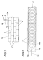
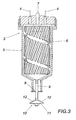
- a distributor head 3 is provided, to which the two components of the two-component adhesive, for example a polyol and an isocyanate compound, are supplied via a respective supply line 4.
- the distributor head 3 has a housing 5 for a mixing rotor 6, which is driven in a known manner by a shaft 7.
- the mixed from the two components in the housing 5 by means of the mixing rotor 6 two-component adhesive is discharged by means of the mixing rotor 6 from the housing 5 through an outlet nozzle 8, which is penetrated by a connected to the mixing rotor 6 guide shaft 9.
- This guide shaft 9 carries at its end projecting from the outlet nozzle 8, a distributor plate 10 which has a guide surface 11 sloping radially outwardly from the guide shaft 9 with substantially radially extending guide webs 12.
- the mixture produced by means of the mixing rotor 6 in the housing 5 from the two components of the two-component adhesive is thus discharged through the outlet nozzle 8 along the guide shaft 9 to flow from the guide shaft 9 along the sloping guide surface 11 of the distributor plate 10 to the outside and centrifugal force centrifuged by the guide ribs 12 in relatively thin jets, as this is indicated in Fig. 1.
- the adhesive beams 13, 14 do not travel along circular paths on the application surface 15 but along interlocking loops, as shown in FIG. It can be seen that the loop course 13a of the one guide web 12 associated adhesive jet 13 is offset from the loop course 14a of the other Leitsteg associated adhesive jet 14, so that a fine distribution of applied in the form of Schlingenverêtn 13a and 14a two-component adhesive on the application surface 15th results.
- the width of the application area depends on otherwise constant parameters only from the distance of the distributor head 3 from the application surface 15 and can therefore be changed over this distance.
Landscapes
- Engineering & Computer Science (AREA)
- Architecture (AREA)
- Chemical & Material Sciences (AREA)
- Chemical Kinetics & Catalysis (AREA)
- Mechanical Engineering (AREA)
- Civil Engineering (AREA)
- Structural Engineering (AREA)
- Coating Apparatus (AREA)
- Application Of Or Painting With Fluid Materials (AREA)
- Conveying And Assembling Of Building Elements In Situ (AREA)
- Finishing Walls (AREA)
- Nozzles (AREA)
Description
- Die Erfindung bezieht sich auf eine Vorrichtung zum Auftragen eines Zweikomponentenklebers auf eine Bausteinschar eines scharenweise aus Bausteinen aufgebauten Bausteinverbundes mit wenigstens einem parallel zur Auftragsfläche relativ zur Bausteinschar bewegbaren Verteilerkopf, der ein an je eine Versorgungsleitung für die Kleberkomponenten angeschlossenes Gehäuse mit einem Mischrotor und einer zum Mischrotor koaxialen Austrittsdüse für den Zweikomponentenkleber umfaßt.
- Zum Herstellen eines Bausteinverbundes aus scharenweise verlegten Bausteinen, beispielsweise für Wände, ist es bekannt (
WO 98/10030 A1 DE 295 16 077 U1 bekannte Vorrichtung zum Mischen und Auftragen eines Zweikomponentenklebers weist ein mit einem Mischrotor versehenes Gehäuse auf, das an die Versorgungsleitungen für die beiden Kleberkomponenten angeschlossen ist und eine koaxial zum Mischrotor angeordnete Austrittsdüse aufweist, durch die der aus den beiden zugeführten Komponenten gemischte Zweikomponentenkleber austritt. Bei einer entsprechenden Relativbewegung eines mit Hilfe einer solchen Vorrichtung gebildeten Verteilerkopfes gegenüber einer Auftragsfläche kann somit der Zweikomponentenkleber in einem Strang aufgetragen werden. Dieser über die Auftragsfläche beispielsweise mäanderförmig verteilte Kleberstrang müßte jedoch zusätzlich über die Auftragsfläche verteilt werden, um einen für einen fugendichten Bausteinverbund erforderlichen dünnschichtigen Kleberauftrag zu erreichen. - Der Erfindung liegt somit die Aufgabe zugrunde, eine Vorrichtung zum Auftragen eines Zweikomponentenklebers auf eine Bausteinschar eines scharenweise aus Bausteinen aufgebauten Bausteinverbundes der eingangs geschilderten Art so auszugestalten, daß ein für ein vorteilhaftes Fügen der Bausteine ausreichend dünnschichtiger Auftrag des Zweikomponentenklebers auf die Auftragsfläche sichergestellt werden kann.
- Die Erfindung löst die gestellte Aufgabe dadurch, daß der Mischrotor eine die Austrittsdüse durchsetzende Führungswelle mit einem endseitigen Verteilerteller trägt, der rotationssymmetrisch angeordnete Leitstege aufweist.
- Zufolge dieser Maßnahme wird der im Gehäuse des Verteilerkopfes gemischte Zweikomponentenkleber entlang der Führungswelle durch die Austrittsdüse bis zum endseitigen Verteilerteller gefördert, von dem er fliehkraftbedingt abgeschleudert wird, und zwar entlang der Leitstege, die zur Vermeidung von Unwuchten rotationssymmetrisch angeordnet sind. Der Zweikomponentenkleber wird daher auf einer zur vertikalen Achse des Verteilerkopfes senkrechten, diesem Verteilerkopf gegenüber stillstehenden Auftragsfläche in Kreisbahnen aufgebracht, deren Anzahl der Anzahl der Leitstege entspricht und deren Durchmesser bei gegebener Fördermenge von der Ausgestaltung des Verteilertellers und dessen Drehzahl einerseits und vom Abstand des Verteilertellers von der Auftragsfläche anderseits abhängt, so daß bei den jeweiligen Konstruktionsvorgaben der Kreisdurchmesser durch eine Verstellung des Verteilerkopfes senkrecht zur Auftragsfläche verändert werden kann. Wird der Verteilerkopf parallel zur Auftragsfläche relativ zu dieser bewegt, so überlagert sich der Umlaufgeschwindigkeit der abgeschleuderten Kleberteilströme die Relativgeschwindigkeit zwischen dem Verteilerkopf und der Auftragsfläche, so daß die Kreisbahnen in Richtung der Relativbewegung verzerrt werden und der Zweikomponentenkleber entlang von ineinandergreifenden Schlingen aufgebracht wird, deren Durchmesser senkrecht zur Relativbewegung den vom Abstand des stand des Verteilerkopfes von der Auftragsfläche abhängigen Kreisbahnen entspricht und deren Durchmesser in Richtung der Relativbewegung in Abhängigkeit von der Relativgeschwindigkeit gegenüber den Kreisbahnen verkürzt sind. Da aufgrund der Relativbewegung zwischen dem Verteilerkopf und der Auftragsfläche die Bahnschlingen, entlang der die Kleberteilströme von den einzelnen Leitstegen aufgebracht werden, gegeneinander in Richtung der Relativbewegung versetzt sind, ergibt sich eine feine Verteilung des Zweikomponentenklebers über die Auftragsfläche, zumal die durch die Austrittsdüse des Verteilerkopfes ausgeförderte Klebermenge aufgrund einer entsprechenden Drehzahl des Fördertellers in Form von vergleichsweise feinen Strahlen auf die Auftragsfläche abgeschleudert werden. Damit ist in einfacher Weise ein maschineller Auftrag eines Zweikomponentenklebers auf eine Bausteinschar eines scharenweise aus Bausteinen aufgebauten Bausteinverbundes möglich, und zwar in einer den jeweiligen Anforderungen anpaßbaren Dünnschichtigkeit. Das Abschleudern des Zweikomponentenklebers in Teilströmen entlang von Leitstegen des Verteilertellers macht außerdem die Bedingungen für die Schleuderweite weitgehend unabhängig von unvermeidbaren Schwankungen hinsichtlich der Viskosität des ausgeförderten Klebergemisches, so daß es keiner aufwendigen Steuereinrichtung bedarf, um eine gleichmäßige, der breite der Bausteine angepaßte Auftragsbreite sicherstellen zu können.
- Besonders einfache Konstruktionsverhältnisse ergeben sich, wenn der Verteilerteller eine nach außen abfallende konische Leitfläche für den Zweikomponentenkleber bildet, der während der Strömungsbewegung radial nach außen von den Leitstegen erfaßt und vom Verteilerteller abgeschleudert wird. Wie bereits ausgeführt wurde, hängt die Auftragsbreite des in Teilströmen abgeschleuderten Zweikomponentenklebers vom Abstand des Verteilerkopfes senkrecht zur Auftragsfläche ab. Zur Anpassung der Auftragsvorrichtung an die jeweilige Bausteinbreite kann daher der Verteilerkopf senkrecht zur Auftragsfläche verstellbar angeordnet werden. Es genügt folglich, daß der in seinem Abstand eingestellte Verteilerkopf in Längsrichtung der Bausteinschar verschiebbar gelagert wird, um vorteilhafte Voraussetzungen für einen dünnschichtigen Auftrag des Zweikomponentenklebers auf die jeweilige Bausteinschar des aufzubauenden Bausteinverbundes sicherzustellen. Da im allgemeinen die Bausteine zur Herstellung eines Bausteinverbundes in einem die gegenseitige Ausrichtung der Bausteine sicherstellenden Gestell verlegt werden, braucht die Führung des Verteilerkopfes lediglich diesem Gestell zugeordnet zu werden.
- In der Zeichnung ist der Erfindungsgegenstand beispielsweise dargestellt. Es zeigen
- Fig. 1
- eine erfindungsgemäße Vorrichtung zum Auftragen eines Zweikomponentenklebers auf eine Bausteinschar eines scharenweise aus Bausteinen aufgebauten Bausteinverbundes in einer schematischen Seitenansicht,
- Fig. 2
- die durch eine Bausteinschar gebildete Auftragsfläche mit dem in Form von ineinandergreifenden Schlingen aufgebrachten Zweikomponentenkleber in einem größeren Maßstab und
- Fig. 3
- den Verteilerkopf einer erfindungsgemäßen Vorrichtung ausschnittsweise in einem vereinfachten Axialschnitt in einem größeren Maßstab.
- Um einen selbsttragenden Bausteinverbund aus scharenweise versetzten Bausteinen herzustellen, werden die einzelnen in üblicher Weise gegeneinander versetzten Bausteinscharen 2 miteinander verklebt, und zwar mit Hilfe eines Zweikomponentenklebers, der dünnschichtig auf die jeweils oberste Bausteinschar 2 aufgebracht wird. Zu diesem Zweck ist ein Verteilerkopf 3 vorgesehen, dem die beiden Komponenten des Zweikomponentenklebers, beispielsweise ein Polyol und eine Isocyanatverbindung, über je eine Versorgungsleitung 4 zugeführt werden. Der Verteilerkopf 3 weist gemäß der Fig. 3 ein Gehäuse 5 für einen Mischrotor 6 auf, der durch eine Welle 7 in bekannter Weise angetrieben wird. Der aus den beiden Komponenten im Gehäuse 5 mit Hilfe des Mischrotors 6 gemischte Zweikomponentenkleber wird mittels des Mischrotors 6 aus dem Gehäuse 5 durch eine Austrittsdüse 8 ausgefördert, die von einer mit dem Mischrotor 6 verbundenen Führungswelle 9 durchsetzt wird. Diese Führungswelle 9 trägt an ihrem aus der Austrittsdüse 8 vorstehenden Ende einen Verteilerteller 10 der eine von der Führungswelle 9 radial nach außen abfallende Leitfläche 11 mit im wesentlichen radial verlaufenden Leitstegen 12 aufweist. Das mit Hilfe des Mischrotors 6 im Gehäuse 5 hergestellte Gemisch aus den beiden Komponenten des Zweikomponentenklebers wird somit durch die Austrittsdüse 8 entlang der Führungswelle 9 ausgefördert, um von der Führungswelle 9 entlang der abfallenden Leitfläche 11 des Verteilertellers 10 nach außen abzufließen und fliehkraftbedingt durch die Leitstege 12 in vergleichsweise dünnen Strahlen abgeschleudert zu werden, wie dies in der Fig. 1 angedeutet ist. Unter der Annahme von zwei Leitstegen 12 ergeben sich zwei Kleberstrahlen 13 und 14, die um die Achse des Mischrotors 6 umlaufen. Da der Verteilerkopf 3 gegenüber dem Bausteinverbund in Längsrichtung der Bausteinscharen 2 parallel zu der durch die jeweils oberste Bausteinschar 2 gegebenen Auftragsfläche 15 verlagert wird, wie dies durch den Pfeil 16 angedeutet ist, werden die Kleberstrahlen 13, 14 nicht entlang von Kreisbahnen auf der Auftragsfläche 15 aufgetragen, sondern entlang von ineinandergreifenden Schlingen, wie dies in der Fig. 2 dargestellt ist. Es zeigt sich, daß der Schlingenverlauf 13a des dem einen Leitsteg 12 zugehörigen Kleberstrahls 13 gegenüber dem Schlingenverlauf 14a des dem andern Leitsteg zugehörigen Kleberstrahls 14 versetzt ist, so daß sich eine feine Verteilung des in Form von Schlingenverläufen 13a und 14a aufgebrachten Zweikomponentenklebers über die Auftragsfläche 15 ergibt. Die Breite des Auftragsbereiches hängt bei sonst gleichbleibendem Parameter ausschließlich vom Abstand des Verteilerkopfes 3 von der Auftragsfläche 15 ab und kann daher auch über diesen Abstand verändert werden. Mit einem senkrecht zur Auftragsfläche 15 verlagerbaren Verteilerkopf 3 läßt sich somit die Vorrichtung zum Auftragen eines Zweikomponentenklebers auf eine Bausteinschar in einfacher Weise auf die jeweilige Bausteinbreite einstellen.
Claims (4)
- Vorrichtung zum Auftragen eines Zweikomponentenklebers auf eine Bausteinschar (2) eines scharenweise aus Bausteinen (1) aufgebauten Bausteinverbundes, mit wenigstens einem parallel zur Auftragsfläche (15) relativ zur Bausteinschar (2) bewegbaren Verteilerkopf (3), der ein an je eine Versorgungsleitung (4) für die Kleberkomponenten angeschlossenes Gehäuse (5) mit einem Mischrotor (6) und einer zum Mischrotor (6) koaxialen Austrittsdüse (8) für den Zweikomponentenkleber umfaßt, dadurch gekennzeichnet, daß der Mischrotor (6) eine die Austrittsdüse (8) durchsetzende Führungswelle (9) mit einem endseitigen Verteilerteller (10) trägt, der rotationssymmetrisch angeordnete Leitstege (12) aufweist.
- Vorrichtung nach Anspruch 1, dadurch gekennzeichnet, daß der Verteilerteller (10) eine nach außen abfallende konische Leitfläche (11) für den Zweikomponentenkleber bildet.
- Vorrichtung nach Anspruch 1 oder 2, dadurch gekennzeichnet, daß der Verteilerkopf (3) senkrecht zur Auftragsfläche (15) verstellbar ist.
- Vorrichtung nach einem der Ansprüche 1 bis 3, dadurch gekennzeichnet, daß der Verteilerkopf (3) in Längsrichtung (16) der Bausteinschar (2) verschiebbar gelagert ist.
Applications Claiming Priority (1)
| Application Number | Priority Date | Filing Date | Title |
|---|---|---|---|
| AT0185804A AT503555B1 (de) | 2004-11-08 | 2004-11-08 | Vorrichtung zum auftragen eines zweikomponentenklebers auf eine bausteinschar eines scharenweise aus bausteinen aufgebauten bausteinverbundes |
Publications (2)
| Publication Number | Publication Date |
|---|---|
| EP1655425A1 EP1655425A1 (de) | 2006-05-10 |
| EP1655425B1 true EP1655425B1 (de) | 2007-09-26 |
Family
ID=35697134
Family Applications (1)
| Application Number | Title | Priority Date | Filing Date |
|---|---|---|---|
| EP05450177A Expired - Lifetime EP1655425B1 (de) | 2004-11-08 | 2005-10-25 | Vorrichtung zum Auftragen eines Zweikomponentenklebers auf eine Bausteinschar eines scharenweise aus Bausteinen aufgebauten Bausteinverbundes |
Country Status (3)
| Country | Link |
|---|---|
| EP (1) | EP1655425B1 (de) |
| AT (2) | AT503555B1 (de) |
| DE (1) | DE502005001563D1 (de) |
Families Citing this family (1)
| Publication number | Priority date | Publication date | Assignee | Title |
|---|---|---|---|---|
| CN106168069B (zh) * | 2014-12-11 | 2018-06-12 | 孙明余 | 建筑砌墙工具 |
Family Cites Families (5)
| Publication number | Priority date | Publication date | Assignee | Title |
|---|---|---|---|---|
| BE757323A (fr) * | 1969-10-22 | 1971-03-16 | C E P R A Ceramique Productivi | Procedes d'assemblage d'elements de construction |
| DE3416280A1 (de) * | 1984-05-03 | 1985-11-07 | Hartmut 2201 Seestermühe Grotjan | Vorrichtung zur erzeugung eines kleberauftrages fuer bausteine oder dergleichen |
| DE29516077U1 (de) * | 1995-10-10 | 1997-02-06 | Maslanka, Harald, 78532 Tuttlingen | Sprühvorrichtung |
| DE29615577U1 (de) | 1996-09-06 | 1998-01-15 | H.B. Fuller Licensing & Financing, Inc., St. Paul, Minn. | Reaktive 2-Komponenten Polyurethan-Klebstoffzusammensetzung, insbesondere geeignet zum Verkleben von Kalksandstein u.dgl. |
| DE29814292U1 (de) * | 1998-08-10 | 1998-11-05 | B & B Maschinenfabrik GmbH, 48496 Hopsten | Auftragsdüse zum maschinellen Auftragen eines Mauerwerkbindemittels |
-
2004
- 2004-11-08 AT AT0185804A patent/AT503555B1/de not_active IP Right Cessation
-
2005
- 2005-10-25 AT AT05450177T patent/ATE374296T1/de active
- 2005-10-25 DE DE502005001563T patent/DE502005001563D1/de not_active Expired - Lifetime
- 2005-10-25 EP EP05450177A patent/EP1655425B1/de not_active Expired - Lifetime
Also Published As
| Publication number | Publication date |
|---|---|
| AT503555B1 (de) | 2007-11-15 |
| ATE374296T1 (de) | 2007-10-15 |
| AT503555A4 (de) | 2007-11-15 |
| EP1655425A1 (de) | 2006-05-10 |
| DE502005001563D1 (de) | 2007-11-08 |
Similar Documents
| Publication | Publication Date | Title |
|---|---|---|
| DE3879920T3 (de) | Spritzdüse für Dosierkopf mit einer Zahnradpumpe. | |
| EP2620223B1 (de) | Düseneinheit und Spender mit einer solchen | |
| DE60117431T2 (de) | Klebstoffdüse mit einem geteilten Auslass | |
| DE2615111A1 (de) | Verstellbarer duschkopf | |
| DE3304129A1 (de) | Verfahren und mischer zum kontinuierlichen beleimen von aus holz-spaenen, -fasern od. dgl. bestehendem mischgut | |
| EP0938931A2 (de) | Spritzvorrichtung zum Zerstäuben von Flüssigkeiten | |
| EP1470864B1 (de) | Zweistoffsprühdüse | |
| DE2140552C3 (de) | Vorrichtung zur Herstellung eines Wirrfaservlieses | |
| EP1655425B1 (de) | Vorrichtung zum Auftragen eines Zweikomponentenklebers auf eine Bausteinschar eines scharenweise aus Bausteinen aufgebauten Bausteinverbundes | |
| DE2359413C3 (de) | Vorrichtung zum Beschichten laufender Werkstoffbahnen aus Papier, Karton, Kunststoff o.dgl. | |
| DE102004018597B3 (de) | Applikationskopf zur Erzeugung einer Flüssigfolie | |
| LV11293B (en) | A glue mixing device | |
| DE60318956T2 (de) | Verfahren und vorrichtung zum auftragen einer beschichtigung auf einen um eine achse rotierenden körper | |
| WO2016138928A1 (de) | Umschaltbare düsenanordnung | |
| CH685713A5 (de) | Vorrichtung zum Herstellen eines Faservlieses. | |
| DE3233744A1 (de) | Verfahren zum mischen von trockengemisch und wasser beim trockenspritzen und mischrohr fuer das trockenspritzverfahren | |
| DE202014101462U1 (de) | Vorrichtung zur Erzeugung von Flüssigkeitsnebel | |
| EP2852705B1 (de) | Kaskadendüse zum auftragen mehrerer schichten | |
| EP0728241A1 (de) | Auftragswerk zum direkten oder indirekten auftragen eines flüssigen oder pastösen mediums auf eine laufende materialbahn | |
| DE3404565C2 (de) | Verteilsystem zur tropfenförmigen Verteilung flüssiger Medien | |
| DE202012104931U1 (de) | Vorrichtung zum Aufbringen eines flüssigen Mediums auf eine Faserbahn | |
| DE4235617C1 (de) | Verfahren und Vorrichtung zur Herstellung gestreifter, mehrfarbiger Seife in verschiedensten Musterungen | |
| DE10016509A1 (de) | Verfahren zur Rohrinnenbeschichtung und Fahrwagen mit Mischkegel | |
| EP0085876B1 (de) | Vorrichtung zum Erzeugen eines chemisch reaktionsfähigen Gemisches | |
| DE3804827C2 (de) |
Legal Events
| Date | Code | Title | Description |
|---|---|---|---|
| PUAI | Public reference made under article 153(3) epc to a published international application that has entered the european phase |
Free format text: ORIGINAL CODE: 0009012 |
|
| AK | Designated contracting states |
Kind code of ref document: A1 Designated state(s): AT BE BG CH CY CZ DE DK EE ES FI FR GB GR HU IE IS IT LI LT LU LV MC NL PL PT RO SE SI SK TR |
|
| AX | Request for extension of the european patent |
Extension state: AL BA HR MK YU |
|
| 17P | Request for examination filed |
Effective date: 20061023 |
|
| 17Q | First examination report despatched |
Effective date: 20061208 |
|
| AKX | Designation fees paid |
Designated state(s): AT BE BG CH CY CZ DE DK EE ES FI FR GB GR HU IE IS IT LI LT LU LV MC NL PL PT RO SE SI SK TR |
|
| GRAP | Despatch of communication of intention to grant a patent |
Free format text: ORIGINAL CODE: EPIDOSNIGR1 |
|
| GRAS | Grant fee paid |
Free format text: ORIGINAL CODE: EPIDOSNIGR3 |
|
| GRAA | (expected) grant |
Free format text: ORIGINAL CODE: 0009210 |
|
| AK | Designated contracting states |
Kind code of ref document: B1 Designated state(s): AT BE BG CH CY CZ DE DK EE ES FI FR GB GR HU IE IS IT LI LT LU LV MC NL PL PT RO SE SI SK TR |
|
| REG | Reference to a national code |
Ref country code: GB Ref legal event code: FG4D Free format text: NOT ENGLISH |
|
| REG | Reference to a national code |
Ref country code: CH Ref legal event code: EP |
|
| REF | Corresponds to: |
Ref document number: 502005001563 Country of ref document: DE Date of ref document: 20071108 Kind code of ref document: P |
|
| REG | Reference to a national code |
Ref country code: IE Ref legal event code: FG4D Free format text: LANGUAGE OF EP DOCUMENT: GERMAN |
|
| GBT | Gb: translation of ep patent filed (gb section 77(6)(a)/1977) |
Effective date: 20080103 |
|
| PG25 | Lapsed in a contracting state [announced via postgrant information from national office to epo] |
Ref country code: FI Free format text: LAPSE BECAUSE OF FAILURE TO SUBMIT A TRANSLATION OF THE DESCRIPTION OR TO PAY THE FEE WITHIN THE PRESCRIBED TIME-LIMIT Effective date: 20070926 Ref country code: LT Free format text: LAPSE BECAUSE OF FAILURE TO SUBMIT A TRANSLATION OF THE DESCRIPTION OR TO PAY THE FEE WITHIN THE PRESCRIBED TIME-LIMIT Effective date: 20070926 |
|
| PG25 | Lapsed in a contracting state [announced via postgrant information from national office to epo] |
Ref country code: PL Free format text: LAPSE BECAUSE OF FAILURE TO SUBMIT A TRANSLATION OF THE DESCRIPTION OR TO PAY THE FEE WITHIN THE PRESCRIBED TIME-LIMIT Effective date: 20070926 |
|
| PG25 | Lapsed in a contracting state [announced via postgrant information from national office to epo] |
Ref country code: LV Free format text: LAPSE BECAUSE OF FAILURE TO SUBMIT A TRANSLATION OF THE DESCRIPTION OR TO PAY THE FEE WITHIN THE PRESCRIBED TIME-LIMIT Effective date: 20070926 |
|
| PG25 | Lapsed in a contracting state [announced via postgrant information from national office to epo] |
Ref country code: ES Free format text: LAPSE BECAUSE OF FAILURE TO SUBMIT A TRANSLATION OF THE DESCRIPTION OR TO PAY THE FEE WITHIN THE PRESCRIBED TIME-LIMIT Effective date: 20080106 Ref country code: GR Free format text: LAPSE BECAUSE OF FAILURE TO SUBMIT A TRANSLATION OF THE DESCRIPTION OR TO PAY THE FEE WITHIN THE PRESCRIBED TIME-LIMIT Effective date: 20071227 |
|
| REG | Reference to a national code |
Ref country code: IE Ref legal event code: FD4D |
|
| ET | Fr: translation filed | ||
| PG25 | Lapsed in a contracting state [announced via postgrant information from national office to epo] |
Ref country code: IS Free format text: LAPSE BECAUSE OF FAILURE TO SUBMIT A TRANSLATION OF THE DESCRIPTION OR TO PAY THE FEE WITHIN THE PRESCRIBED TIME-LIMIT Effective date: 20080126 Ref country code: PT Free format text: LAPSE BECAUSE OF FAILURE TO SUBMIT A TRANSLATION OF THE DESCRIPTION OR TO PAY THE FEE WITHIN THE PRESCRIBED TIME-LIMIT Effective date: 20080226 Ref country code: MC Free format text: LAPSE BECAUSE OF NON-PAYMENT OF DUE FEES Effective date: 20071031 |
|
| PG25 | Lapsed in a contracting state [announced via postgrant information from national office to epo] |
Ref country code: SE Free format text: LAPSE BECAUSE OF FAILURE TO SUBMIT A TRANSLATION OF THE DESCRIPTION OR TO PAY THE FEE WITHIN THE PRESCRIBED TIME-LIMIT Effective date: 20071226 Ref country code: RO Free format text: LAPSE BECAUSE OF FAILURE TO SUBMIT A TRANSLATION OF THE DESCRIPTION OR TO PAY THE FEE WITHIN THE PRESCRIBED TIME-LIMIT Effective date: 20070926 |
|
| REG | Reference to a national code |
Ref country code: HU Ref legal event code: AG4A Ref document number: E002826 Country of ref document: HU |
|
| PG25 | Lapsed in a contracting state [announced via postgrant information from national office to epo] |
Ref country code: DK Free format text: LAPSE BECAUSE OF FAILURE TO SUBMIT A TRANSLATION OF THE DESCRIPTION OR TO PAY THE FEE WITHIN THE PRESCRIBED TIME-LIMIT Effective date: 20070926 |
|
| PLBE | No opposition filed within time limit |
Free format text: ORIGINAL CODE: 0009261 |
|
| STAA | Information on the status of an ep patent application or granted ep patent |
Free format text: STATUS: NO OPPOSITION FILED WITHIN TIME LIMIT |
|
| 26N | No opposition filed |
Effective date: 20080627 |
|
| PG25 | Lapsed in a contracting state [announced via postgrant information from national office to epo] |
Ref country code: IE Free format text: LAPSE BECAUSE OF FAILURE TO SUBMIT A TRANSLATION OF THE DESCRIPTION OR TO PAY THE FEE WITHIN THE PRESCRIBED TIME-LIMIT Effective date: 20070926 |
|
| PG25 | Lapsed in a contracting state [announced via postgrant information from national office to epo] |
Ref country code: EE Free format text: LAPSE BECAUSE OF FAILURE TO SUBMIT A TRANSLATION OF THE DESCRIPTION OR TO PAY THE FEE WITHIN THE PRESCRIBED TIME-LIMIT Effective date: 20070926 |
|
| PG25 | Lapsed in a contracting state [announced via postgrant information from national office to epo] |
Ref country code: SI Free format text: LAPSE BECAUSE OF FAILURE TO SUBMIT A TRANSLATION OF THE DESCRIPTION OR TO PAY THE FEE WITHIN THE PRESCRIBED TIME-LIMIT Effective date: 20070926 |
|
| PG25 | Lapsed in a contracting state [announced via postgrant information from national office to epo] |
Ref country code: CY Free format text: LAPSE BECAUSE OF FAILURE TO SUBMIT A TRANSLATION OF THE DESCRIPTION OR TO PAY THE FEE WITHIN THE PRESCRIBED TIME-LIMIT Effective date: 20070926 |
|
| PG25 | Lapsed in a contracting state [announced via postgrant information from national office to epo] |
Ref country code: LU Free format text: LAPSE BECAUSE OF NON-PAYMENT OF DUE FEES Effective date: 20071025 Ref country code: BG Free format text: LAPSE BECAUSE OF FAILURE TO SUBMIT A TRANSLATION OF THE DESCRIPTION OR TO PAY THE FEE WITHIN THE PRESCRIBED TIME-LIMIT Effective date: 20071226 |
|
| PG25 | Lapsed in a contracting state [announced via postgrant information from national office to epo] |
Ref country code: TR Free format text: LAPSE BECAUSE OF FAILURE TO SUBMIT A TRANSLATION OF THE DESCRIPTION OR TO PAY THE FEE WITHIN THE PRESCRIBED TIME-LIMIT Effective date: 20070926 |
|
| REG | Reference to a national code |
Ref country code: GB Ref legal event code: 732E Free format text: REGISTERED BETWEEN 20100121 AND 20100127 |
|
| NLS | Nl: assignments of ep-patents |
Owner name: REDBLOC BETEILIGUNGS GMBH Effective date: 20100202 |
|
| REG | Reference to a national code |
Ref country code: FR Ref legal event code: TP |
|
| REG | Reference to a national code |
Ref country code: HU Ref legal event code: GB9C Owner name: REDBLOC BETEILIGUNGS GMBH, AT Free format text: FORMER OWNER(S): WALZER, FRIEDRICH, AT Ref country code: HU Ref legal event code: FH1C Free format text: FORMER REPRESENTATIVE(S): MESTER TAMAS, SWORKS NEMZETKOEZI SZABADALMI UEGYVIVOEI IRODA KFT., HU Representative=s name: MESTER TAMAS, SWORKS NEMZETKOEZI SZABADALMI UE, HU |
|
| REG | Reference to a national code |
Ref country code: CH Ref legal event code: PL |
|
| REG | Reference to a national code |
Ref country code: SK Ref legal event code: PC4A Ref document number: E 3347 Country of ref document: SK Owner name: REDBLOC BETEILIGUNGS GMBH, WELS, AT Free format text: FORMER OWNER: WALZER FRIEDRICH, RETZ, AT Effective date: 20091204 |
|
| REG | Reference to a national code |
Ref country code: CH Ref legal event code: AEN Free format text: DAS PATENT IST AUFGRUND DES WEITERBEHANDLUNGSANTRAGS VOM 13.07.2010 REAKTIVIERT WORDEN. |
|
| PG25 | Lapsed in a contracting state [announced via postgrant information from national office to epo] |
Ref country code: LI Free format text: LAPSE BECAUSE OF NON-PAYMENT OF DUE FEES Effective date: 20091031 |
|
| PGRI | Patent reinstated in contracting state [announced from national office to epo] |
Ref country code: CH Effective date: 20100730 |
|
| PG25 | Lapsed in a contracting state [announced via postgrant information from national office to epo] |
Ref country code: IT Free format text: LAPSE BECAUSE OF NON-PAYMENT OF DUE FEES Effective date: 20071031 |
|
| REG | Reference to a national code |
Ref country code: CH Ref legal event code: PL |
|
| REG | Reference to a national code |
Ref country code: CH Ref legal event code: AEN Free format text: DAS PATENT IST AUFGRUND DES WEITERBEHANDLUNGSANTRAGS VOM 11.07.2011 REAKTIVIERT WORDEN. |
|
| PG25 | Lapsed in a contracting state [announced via postgrant information from national office to epo] |
Ref country code: CH Free format text: LAPSE BECAUSE OF NON-PAYMENT OF DUE FEES Effective date: 20101031 Ref country code: LI Free format text: LAPSE BECAUSE OF NON-PAYMENT OF DUE FEES Effective date: 20101031 |
|
| PGFP | Annual fee paid to national office [announced via postgrant information from national office to epo] |
Ref country code: CH Payment date: 20110711 Year of fee payment: 6 |
|
| PGRI | Patent reinstated in contracting state [announced from national office to epo] |
Ref country code: CH Effective date: 20110711 |
|
| REG | Reference to a national code |
Ref country code: CH Ref legal event code: PL |
|
| PG25 | Lapsed in a contracting state [announced via postgrant information from national office to epo] |
Ref country code: CH Free format text: LAPSE BECAUSE OF NON-PAYMENT OF DUE FEES Effective date: 20111031 Ref country code: LI Free format text: LAPSE BECAUSE OF NON-PAYMENT OF DUE FEES Effective date: 20111031 |
|
| PGFP | Annual fee paid to national office [announced via postgrant information from national office to epo] |
Ref country code: GB Payment date: 20131029 Year of fee payment: 9 Ref country code: SK Payment date: 20131018 Year of fee payment: 9 Ref country code: CZ Payment date: 20131018 Year of fee payment: 9 |
|
| PGFP | Annual fee paid to national office [announced via postgrant information from national office to epo] |
Ref country code: NL Payment date: 20131026 Year of fee payment: 9 Ref country code: HU Payment date: 20131223 Year of fee payment: 9 |
|
| REG | Reference to a national code |
Ref country code: NL Ref legal event code: V1 Effective date: 20150501 |
|
| GBPC | Gb: european patent ceased through non-payment of renewal fee |
Effective date: 20141025 |
|
| REG | Reference to a national code |
Ref country code: SK Ref legal event code: MM4A Ref document number: E 3347 Country of ref document: SK Effective date: 20141025 |
|
| PG25 | Lapsed in a contracting state [announced via postgrant information from national office to epo] |
Ref country code: GB Free format text: LAPSE BECAUSE OF NON-PAYMENT OF DUE FEES Effective date: 20141025 Ref country code: CZ Free format text: LAPSE BECAUSE OF NON-PAYMENT OF DUE FEES Effective date: 20141025 Ref country code: SK Free format text: LAPSE BECAUSE OF NON-PAYMENT OF DUE FEES Effective date: 20141025 |
|
| PG25 | Lapsed in a contracting state [announced via postgrant information from national office to epo] |
Ref country code: NL Free format text: LAPSE BECAUSE OF NON-PAYMENT OF DUE FEES Effective date: 20150501 Ref country code: HU Free format text: LAPSE BECAUSE OF NON-PAYMENT OF DUE FEES Effective date: 20141026 |
|
| REG | Reference to a national code |
Ref country code: FR Ref legal event code: PLFP Year of fee payment: 11 |
|
| REG | Reference to a national code |
Ref country code: FR Ref legal event code: PLFP Year of fee payment: 12 |
|
| REG | Reference to a national code |
Ref country code: FR Ref legal event code: PLFP Year of fee payment: 13 |
|
| REG | Reference to a national code |
Ref country code: FR Ref legal event code: PLFP Year of fee payment: 14 |
|
| REG | Reference to a national code |
Ref country code: DE Ref legal event code: R082 Ref document number: 502005001563 Country of ref document: DE Representative=s name: WOLF & WOLF PATENT- UND RECHTSANWALTSGESELLSCH, DE Ref country code: DE Ref legal event code: R081 Ref document number: 502005001563 Country of ref document: DE Owner name: REDBLOCSYSTEMS GMBH, AT Free format text: FORMER OWNER: REDBLOC BETEILIGUNGS GMBH, WELS, AT |
|
| REG | Reference to a national code |
Ref country code: BE Ref legal event code: HC Owner name: REDBLOCSYSTEMS GMBH; AT Free format text: DETAILS ASSIGNMENT: CHANGE OF OWNER(S), CHANGEMENT DE NOM DU PROPRIETAIRE; FORMER OWNER NAME: REDBLOC BETEILIGUNGS GMBH Effective date: 20190130 |
|
| REG | Reference to a national code |
Ref country code: AT Ref legal event code: HC Ref document number: 374296 Country of ref document: AT Kind code of ref document: T Owner name: REDBLOCSYSTEMS GMBH, AT Effective date: 20190506 |
|
| PGFP | Annual fee paid to national office [announced via postgrant information from national office to epo] |
Ref country code: AT Payment date: 20211027 Year of fee payment: 17 |
|
| PGFP | Annual fee paid to national office [announced via postgrant information from national office to epo] |
Ref country code: FR Payment date: 20211027 Year of fee payment: 17 |
|
| PGFP | Annual fee paid to national office [announced via postgrant information from national office to epo] |
Ref country code: DE Payment date: 20221028 Year of fee payment: 18 |
|
| REG | Reference to a national code |
Ref country code: AT Ref legal event code: MM01 Ref document number: 374296 Country of ref document: AT Kind code of ref document: T Effective date: 20221025 |
|
| P01 | Opt-out of the competence of the unified patent court (upc) registered |
Effective date: 20230524 |
|
| PG25 | Lapsed in a contracting state [announced via postgrant information from national office to epo] |
Ref country code: FR Free format text: LAPSE BECAUSE OF NON-PAYMENT OF DUE FEES Effective date: 20221031 Ref country code: AT Free format text: LAPSE BECAUSE OF NON-PAYMENT OF DUE FEES Effective date: 20221025 |
|
| REG | Reference to a national code |
Ref country code: DE Ref legal event code: R119 Ref document number: 502005001563 Country of ref document: DE |
|
| PG25 | Lapsed in a contracting state [announced via postgrant information from national office to epo] |
Ref country code: DE Free format text: LAPSE BECAUSE OF NON-PAYMENT OF DUE FEES Effective date: 20240501 |
|
| PGFP | Annual fee paid to national office [announced via postgrant information from national office to epo] |
Ref country code: BE Payment date: 20241023 Year of fee payment: 20 |
|
| REG | Reference to a national code |
Ref country code: BE Ref legal event code: MK Effective date: 20251025 |