EP1655117A1 - Contre-cylindre pour un dispositif rotatif de coupe ainsi qu'unité de coupe rotative ayant un tel cylindre - Google Patents
Contre-cylindre pour un dispositif rotatif de coupe ainsi qu'unité de coupe rotative ayant un tel cylindre Download PDFInfo
- Publication number
- EP1655117A1 EP1655117A1 EP20050022844 EP05022844A EP1655117A1 EP 1655117 A1 EP1655117 A1 EP 1655117A1 EP 20050022844 EP20050022844 EP 20050022844 EP 05022844 A EP05022844 A EP 05022844A EP 1655117 A1 EP1655117 A1 EP 1655117A1
- Authority
- EP
- European Patent Office
- Prior art keywords
- anvil
- rotary cutting
- cutting unit
- pair
- core
- Prior art date
- Legal status (The legal status is an assumption and is not a legal conclusion. Google has not performed a legal analysis and makes no representation as to the accuracy of the status listed.)
- Granted
Links
- 230000002093 peripheral effect Effects 0.000 description 5
- 238000005452 bending Methods 0.000 description 3
- 229910000831 Steel Inorganic materials 0.000 description 2
- 230000005484 gravity Effects 0.000 description 2
- 239000010959 steel Substances 0.000 description 2
- 230000000694 effects Effects 0.000 description 1
- 238000003754 machining Methods 0.000 description 1
- 239000000463 material Substances 0.000 description 1
- 239000002184 metal Substances 0.000 description 1
- 239000007787 solid Substances 0.000 description 1
Images


Classifications
-
- B—PERFORMING OPERATIONS; TRANSPORTING
- B26—HAND CUTTING TOOLS; CUTTING; SEVERING
- B26D—CUTTING; DETAILS COMMON TO MACHINES FOR PERFORATING, PUNCHING, CUTTING-OUT, STAMPING-OUT OR SEVERING
- B26D7/00—Details of apparatus for cutting, cutting-out, stamping-out, punching, perforating, or severing by means other than cutting
- B26D7/20—Cutting beds
-
- B—PERFORMING OPERATIONS; TRANSPORTING
- B26—HAND CUTTING TOOLS; CUTTING; SEVERING
- B26D—CUTTING; DETAILS COMMON TO MACHINES FOR PERFORATING, PUNCHING, CUTTING-OUT, STAMPING-OUT OR SEVERING
- B26D1/00—Cutting through work characterised by the nature or movement of the cutting member or particular materials not otherwise provided for; Apparatus or machines therefor; Cutting members therefor
- B26D1/01—Cutting through work characterised by the nature or movement of the cutting member or particular materials not otherwise provided for; Apparatus or machines therefor; Cutting members therefor involving a cutting member which does not travel with the work
- B26D1/12—Cutting through work characterised by the nature or movement of the cutting member or particular materials not otherwise provided for; Apparatus or machines therefor; Cutting members therefor involving a cutting member which does not travel with the work having a cutting member moving about an axis
- B26D1/25—Cutting through work characterised by the nature or movement of the cutting member or particular materials not otherwise provided for; Apparatus or machines therefor; Cutting members therefor involving a cutting member which does not travel with the work having a cutting member moving about an axis with a non-circular cutting member
- B26D1/34—Cutting through work characterised by the nature or movement of the cutting member or particular materials not otherwise provided for; Apparatus or machines therefor; Cutting members therefor involving a cutting member which does not travel with the work having a cutting member moving about an axis with a non-circular cutting member moving about an axis parallel to the line of cut
- B26D1/40—Cutting through work characterised by the nature or movement of the cutting member or particular materials not otherwise provided for; Apparatus or machines therefor; Cutting members therefor involving a cutting member which does not travel with the work having a cutting member moving about an axis with a non-circular cutting member moving about an axis parallel to the line of cut and coacting with a rotary member
-
- B—PERFORMING OPERATIONS; TRANSPORTING
- B26—HAND CUTTING TOOLS; CUTTING; SEVERING
- B26F—PERFORATING; PUNCHING; CUTTING-OUT; STAMPING-OUT; SEVERING BY MEANS OTHER THAN CUTTING
- B26F1/00—Perforating; Punching; Cutting-out; Stamping-out; Apparatus therefor
- B26F1/38—Cutting-out; Stamping-out
-
- B—PERFORMING OPERATIONS; TRANSPORTING
- B26—HAND CUTTING TOOLS; CUTTING; SEVERING
- B26F—PERFORATING; PUNCHING; CUTTING-OUT; STAMPING-OUT; SEVERING BY MEANS OTHER THAN CUTTING
- B26F1/00—Perforating; Punching; Cutting-out; Stamping-out; Apparatus therefor
- B26F1/38—Cutting-out; Stamping-out
- B26F1/384—Cutting-out; Stamping-out using rotating drums
-
- B—PERFORMING OPERATIONS; TRANSPORTING
- B26—HAND CUTTING TOOLS; CUTTING; SEVERING
- B26D—CUTTING; DETAILS COMMON TO MACHINES FOR PERFORATING, PUNCHING, CUTTING-OUT, STAMPING-OUT OR SEVERING
- B26D7/00—Details of apparatus for cutting, cutting-out, stamping-out, punching, perforating, or severing by means other than cutting
- B26D7/20—Cutting beds
- B26D2007/202—Rollers or cylinders being pivoted during operation
-
- Y—GENERAL TAGGING OF NEW TECHNOLOGICAL DEVELOPMENTS; GENERAL TAGGING OF CROSS-SECTIONAL TECHNOLOGIES SPANNING OVER SEVERAL SECTIONS OF THE IPC; TECHNICAL SUBJECTS COVERED BY FORMER USPC CROSS-REFERENCE ART COLLECTIONS [XRACs] AND DIGESTS
- Y10—TECHNICAL SUBJECTS COVERED BY FORMER USPC
- Y10T—TECHNICAL SUBJECTS COVERED BY FORMER US CLASSIFICATION
- Y10T83/00—Cutting
- Y10T83/465—Cutting motion of tool has component in direction of moving work
- Y10T83/4766—Orbital motion of cutting blade
- Y10T83/4795—Rotary tool
- Y10T83/483—With cooperating rotary cutter or backup
- Y10T83/4838—With anvil backup
-
- Y—GENERAL TAGGING OF NEW TECHNOLOGICAL DEVELOPMENTS; GENERAL TAGGING OF CROSS-SECTIONAL TECHNOLOGIES SPANNING OVER SEVERAL SECTIONS OF THE IPC; TECHNICAL SUBJECTS COVERED BY FORMER USPC CROSS-REFERENCE ART COLLECTIONS [XRACs] AND DIGESTS
- Y10—TECHNICAL SUBJECTS COVERED BY FORMER USPC
- Y10T—TECHNICAL SUBJECTS COVERED BY FORMER US CLASSIFICATION
- Y10T83/00—Cutting
- Y10T83/768—Rotatable disc tool pair or tool and carrier
- Y10T83/7809—Tool pair comprises rotatable tools
- Y10T83/7851—Tool pair comprises disc and cylindrical anvil
- Y10T83/7855—With adjustable means to urge tool elements together
-
- Y—GENERAL TAGGING OF NEW TECHNOLOGICAL DEVELOPMENTS; GENERAL TAGGING OF CROSS-SECTIONAL TECHNOLOGIES SPANNING OVER SEVERAL SECTIONS OF THE IPC; TECHNICAL SUBJECTS COVERED BY FORMER USPC CROSS-REFERENCE ART COLLECTIONS [XRACs] AND DIGESTS
- Y10—TECHNICAL SUBJECTS COVERED BY FORMER USPC
- Y10T—TECHNICAL SUBJECTS COVERED BY FORMER US CLASSIFICATION
- Y10T83/00—Cutting
- Y10T83/929—Tool or tool with support
- Y10T83/9309—Anvil
- Y10T83/9312—Rotatable type
Definitions
- the present invention relates generally to a rotatable anvil for a rotary cutting unit, and more particularly to a rotatable anvil for a rotary cutting unit including an axle, at least one anvil portion adapted to co-operate with a knife member of a rotary cutter, and a pair of load transmitting portions adapted to abut a pair of abutment members of the rotary cutter, the pair of load transmitting portions being arranged on each side of the anvil portion.
- the present invention also relates to a rotary cutting unit including a rotary cutter and the rotatable anvil.
- a known rotary cutting unit is disclosed in U.S. Patent No. 6,244,148, and includes a rotary cutter in working relationship with a rotary anvil.
- the rotary cutter is provided with a substantially circular-cylindrical body having a surface and at least one knife member protruding from the surface, the radially peripheral part of the knife member having a diameter larger than that of the surface.
- Each side of the rotary cutter is provided with an axle supported in bearings. Between the axles and the surface, i.e. on each side of the surface, a pair of annular abutment members are provided.
- the abutment members have a diameter larger than that of the surface, in order to allow abutment against a pair of load receiving portions of the anvil.
- the anvil is provided with an anvil portion and the pair of load receiving portions.
- the anvil portion is adapted to co-operate with the knife member of the rotary cutter, whereas the load receiving portions are adapted to abut the abutment members of the rotary cutter.
- the anvil is supported in bearings outside the anvil portion and outside the load bearing portions, seen in the axial extension of the anvil.
- the abutment members have a diameter which is substantially the same as the radially peripheral part of the knife member.
- the abutment members are adapted to lie against and transmit loads such that a predetermined pressure is exerted on the load receiving portions of the anvil to achieve a desired cutting property.
- the abutment may also transmit rotation of the rotary cutter drum to the anvil surface, such that it turns in a direction opposite to that of the rotary cutter. A product is cut from a web introduced between the drums by the centrally arranged knife member.
- the described rotary cutter however suffers from the drawback that the portions of the knife members in the axial center of the rotary cutting drum do not cut as precisely as the portions of the knife members closer to the axial periphery thereof. This is due to the fact that the rotary cutting drum exerts a pressure onto the anvil surface via the abutment members, thereby causing the anvil to be bent.
- FIG. 5 illustrating the principle of a prior art anvil A corresponding to the anvil disclosed in U.S. Patent No. 6, 244,148.
- a pair of load receiving portions B are arranged on either sides of the axial extension of an anvil portion C, whereas a pair of annular support surfaces D for cooperating with bearings are arranged on either sides of the pair of load receiving portions B.
- the central portion of the anvil A When load E is applied to the load receiving portions, the central portion of the anvil A will be bent slightly downwards as shown (exaggerated) by the broken line F due to the counter directed force G on the surface D, i. e. at the bearings. Such bending may be denoted negative bending.
- Another prior art rotary cutting unit has an anvil for cooperation with a rotary cutting drum having two or more knife members arranged side by side.
- Such a rotary cutter not only suffers from the drawback described above, but also in that it has a long axial extension, causing the anvil drum and the rotary cutting drum to also be bent by gravity, i.e. the longer and heavier the anvil, the more it will be bent negatively by gravity that will add to the described effect.
- An object of the invention is to is to increase the reliability and the life time of an anvil.
- the invention provides a rotatable anvil for a rotary cutting unit, including an axle, at least one anvil portion adapted to co-operate with a knife member of a rotary cutter, a pair of load transmitting portions adapted to abut a pair of abutment members of the rotary cutter, the pair of load transmitting portions being arranged on each side of the anvil portion, and deflection means provided underneath at least one of the anvil portion and the load transmitting portions.
- the invention provides a rotary cutting unit, including a rotary cutting drum and a rotatable anvil.
- the rotatable anvil includes an axle, at least one anvil portion adapted to co-operate with a knife member of the rotary cutting drum, and a pair of load transmitting portions adapted to abut a pair of abutment members of the rotary cutting drum, the pair of load transmitting portions being arranged on each side of the anvil portion, and deflection means provided underneath at least one of the anvil portion and the load transmitting portions.
- the anvil may include a core and a mantle.
- the deflection means may include at least one annular groove in an interior surface of the mantle.
- the deflection means may include at least one annular groove in an exterior surface of the core.
- the anvil may include a core having axial end surfaces, and the deflection means may include at least one axial groove in the end surfaces.
- the anvil portion may include a single anvil portion.
- the anvil portion may include a plurality of anvil portions.
- the rotary cutter may include at least one centrally disposed knife member, and a single anvil portion.
- the rotary cutter may include a plurality of axially disposed knife members and a plurality of anvil portions adapted to co-operate with at least one of the axially disposed knife members.
- the rotary cutter may include a plurality of axially disposed knife members and a single anvil portion.
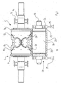
- FIG. 1 shows a first embodiment of a rotary cutting unit 2 according to an embodiment of the invention.
- a rotary cutter 4 is provided with a substantially circular-cylindrical hollow or solid body 6 having a surface 8 and at least one knife member 10 protruding from the surface 8.
- the radially peripheral part 12 of the knife member 10 has a diameter larger than that of the surface 8.
- the rotary cutter 4 is arranged on or is an integral part of an arbour 14 extending axially from each side of the rotary cutter 4 and being supported in bearings 15. Axially on each side of the surface 8, a pair of annular abutment members 16 are provided.
- the abutment members 16 have a diameter larger than that of the surface 8, in order to allow abutment against an anvil drum 18.
- the anvil drum 18 is provided with an axle 19, an anvil portion 20 and a pair of load transmitting portions 22.
- the anvil portion 20 is adapted to co-operate with the knife member 10 of the rotary cutter 4, whereas the load transmitting portions 22 are adapted to abut the abutment surfaces 16 of the rotary cutter 4.
- the abutment members 16 have a diameter which is substantially the same as the radially peripheral part 12 of the knife member 10. In some cases, the diameter of the part 12 may however be larger or smaller than that of the abutment members 16.
- the axle 19 is rotatably arranged at bearings 23, each covered by a load receiving member 24.
- Each load receiving member 24 is arranged axially outside each load transmitting portion 22.
- a load is applied by a pair of pneumatic cylinders 25 to the load receiving members 24.
- the load is transmitted further via the load transmitting portions 22 to the abutment members 16, and optionally also via the knife members 10 to the anvil portion 20.
- the anvil drum 18 includes a substantially circular-cylindrical core 26 and a substantially circular-cylindrical mantle 28 arranged e.g. by press-fit on the core.
- the core 26 is preferably made of steel, whereas the mantle 28 may be made of any suitable material, such as steel or hard metal.
- annular recess 50 is provided in the inner periphery of the mantle 28.
- the annular recess 50 extends such that it is at least partly subjected to the pressure by the knife member 10.
- FIG. 2A two separated knife members 10 adapted to co-operate with two axially separated anvil portions 20 are shown.
- the annular recess 50 extends underneath the load transmitting portions 22 and partially underneath the anvil portions 20.
- FIG. 2B according to a third embodiment, the recess does not extend underneath the load transmitting portions 22, only partially underneath the anvil portions 20.
- FIG. 2C the annular recess 50 extends underneath the load transmitting portions 22 and underneath the anvil portions 20 that are not directly pressed by the knife member 10.
- FIG. 2D a fifth embodiment is shown, according to which the axial annular recess 50 is provided underneath central portions of the knife member 10.
- the extension of the axial annular recess may extend axially further, e.g. a larger part or the whole of the width of the knife member 10. Furthermore, more than one such recesses may be provided. It is contemplated that in such a case, it may be advantageous to provide a plurality of axially separated recesses.
- FIG. 3 a sixth embodiment is shown, according to which the annular groove 50 is made in the core 26 instead of in the mantle 28.
- a seventh embodiment is shown in FIG. 4.
- the anvil drum 18 is constituted solely by said core 26 having axial end surfaces 32.
- the recess 50 shown in FIGS. 1, 2 and 4 is performed by machining an axial groove in the axial surfaces 32 of the core 26. It should be noted that the embodiments of the anvil shown in FIG. 1 - 4 can all be combined in any suitable manner, depending on the desired degree of deflection.
Landscapes
- Life Sciences & Earth Sciences (AREA)
- Forests & Forestry (AREA)
- Engineering & Computer Science (AREA)
- Mechanical Engineering (AREA)
- Perforating, Stamping-Out Or Severing By Means Other Than Cutting (AREA)
- Crushing And Pulverization Processes (AREA)
- Treatment Of Fiber Materials (AREA)
Applications Claiming Priority (1)
| Application Number | Priority Date | Filing Date | Title |
|---|---|---|---|
| SE0402665A SE527845C2 (sv) | 2004-11-03 | 2004-11-03 | En stödvals för en rotationsknivenhet och en rotationsknivenhet med en dylik stödvals |
Publications (2)
| Publication Number | Publication Date |
|---|---|
| EP1655117A1 true EP1655117A1 (fr) | 2006-05-10 |
| EP1655117B1 EP1655117B1 (fr) | 2008-12-24 |
Family
ID=33488144
Family Applications (1)
| Application Number | Title | Priority Date | Filing Date |
|---|---|---|---|
| EP20050022844 Active EP1655117B1 (fr) | 2004-11-03 | 2005-10-20 | Contre-cylindre pour un dispositif rotatif de coupe ainsi qu'unité de coupe rotative ayant un tel cylindre |
Country Status (9)
| Country | Link |
|---|---|
| US (1) | US8336435B2 (fr) |
| EP (1) | EP1655117B1 (fr) |
| JP (1) | JP4927382B2 (fr) |
| KR (1) | KR101164469B1 (fr) |
| CN (1) | CN1972787B (fr) |
| AT (1) | ATE418428T1 (fr) |
| DE (1) | DE602005011917D1 (fr) |
| SE (1) | SE527845C2 (fr) |
| WO (1) | WO2006049549A1 (fr) |
Cited By (2)
| Publication number | Priority date | Publication date | Assignee | Title |
|---|---|---|---|---|
| EP1974878A1 (fr) | 2007-03-30 | 2008-10-01 | Wilhelm Aichele | Dispositif de coupe rotatif |
| EP2531330A1 (fr) * | 2010-02-01 | 2012-12-12 | Unicharm Corporation | Appareil de travail rotatif |
Families Citing this family (7)
| Publication number | Priority date | Publication date | Assignee | Title |
|---|---|---|---|---|
| ES2232258B1 (es) * | 2002-11-28 | 2006-07-16 | Cimco, S.L. | Troqueladora rotativa. |
| JP5336490B2 (ja) * | 2008-07-31 | 2013-11-06 | 日本タングステン株式会社 | 薄板の剪断方法 |
| ITTO20110444A1 (it) * | 2011-05-19 | 2012-11-20 | Tecnau Srl | "equipaggiamento per perforazioni trasversali di lunghezze variabili su moduli continui in movimento" |
| JP6282426B2 (ja) * | 2013-09-05 | 2018-02-21 | 株式会社瑞光 | カッタロール |
| JP5868459B2 (ja) * | 2014-06-30 | 2016-02-24 | ユニ・チャーム株式会社 | 切断装置 |
| JP6148418B1 (ja) | 2016-02-24 | 2017-06-14 | 日本タングステン株式会社 | ロータリーカッター用ロールおよびロータリーカッター |
| KR101674442B1 (ko) * | 2016-04-11 | 2016-11-09 | 김영구 | 스티커 절취장치의 완충 지지용 실린더 |
Citations (3)
| Publication number | Priority date | Publication date | Assignee | Title |
|---|---|---|---|---|
| US5047607A (en) * | 1987-01-30 | 1991-09-10 | Charmilles Technologies S.A. | Wire-cutting electric discharge machine with wire sectioning device for wire disposal |
| DE4215947A1 (de) * | 1991-05-17 | 1992-11-19 | Focke & Co | Vorrichtung zum abtrennen von (kragen-)zuschnitten von einer materialbahn |
| US6244148B1 (en) | 1998-07-29 | 2001-06-12 | Aichele Werkzeuge Gmbh | Cutting device |
Family Cites Families (25)
| Publication number | Priority date | Publication date | Assignee | Title |
|---|---|---|---|---|
| US242058A (en) * | 1881-05-24 | sohtjrmann | ||
| JPS471412Y1 (fr) * | 1967-11-22 | 1972-01-19 | ||
| US3677122A (en) * | 1971-03-23 | 1972-07-18 | Lord Corp | Slitting apparatus having independent resiliently supported anvil means |
| DE2239550A1 (de) * | 1972-08-11 | 1974-02-28 | Berstorff Gmbh Masch Hermann | Walze mit durchbiegungsausgleich |
| DE2251763C3 (de) | 1972-10-21 | 1975-06-05 | Hermann Berstorff Maschinenbau Gmbh, 3000 Hannover | Walze mit Durchbiegungsausgleich zum Auswalzen von plastischen Werkstoffen zu Folienbahnen auf einem Kalander oder Walzwerk |
| US4158128A (en) * | 1977-06-20 | 1979-06-12 | Ivanovsky Nauchno-Issledo-Valetelsky Experimentalnokonstruktorsky Mashinostroitelny Institut | Roller for applying uniform load across the width of processed sheet material |
| US4289055A (en) * | 1980-01-07 | 1981-09-15 | Von Schriltz Don F | Rotary die anvil |
| FR2494166A1 (fr) * | 1980-11-19 | 1982-05-21 | Ruby Ets | Machine pour couper en continu une bande pour former des troncons a bords arrondis ayant des convexites opposees |
| US4553461A (en) * | 1982-10-12 | 1985-11-19 | Magna-Graphics Corporation | Rotary web processing apparatus |
| US4455903A (en) * | 1982-11-15 | 1984-06-26 | Preston Engravers, Inc. | Adjustable anvil roll |
| DE3634198A1 (de) * | 1986-10-08 | 1988-04-21 | Peters W Maschf | Querschneider |
| DE3702869A1 (de) * | 1987-01-31 | 1988-08-11 | Heinz Ditzel | Schneidvorrichtung |
| US4759247A (en) * | 1987-10-22 | 1988-07-26 | Bernal Rotary Systems, Inc. | Rotary dies with adjustable cutter force |
| US5170547A (en) * | 1988-06-28 | 1992-12-15 | Valmet Paper Machinery Inc. | Method and device for balancing a roll |
| DE3915508A1 (de) * | 1989-05-12 | 1990-11-15 | Feldmuehle Ag | Walze zur druckbehandlung von warenbahnen |
| DE3924053A1 (de) * | 1989-07-21 | 1991-01-24 | Wilhelm Aichele | Vorrichtung zum rotationsschneiden von werkstoffbahnen |
| US4989487A (en) * | 1989-07-24 | 1991-02-05 | Staley John P | Anvil assembly for a slitting machine |
| US5083488A (en) * | 1991-04-12 | 1992-01-28 | Melvin Stanley | Radially adjustable anvil roll assembly for a rotary die cutting press |
| US5156076A (en) * | 1991-05-21 | 1992-10-20 | Rosemann Richard R | Radially adjustable anvil roll assembly for a rotary die cutting press |
| EP0671248A3 (fr) * | 1994-03-08 | 1996-03-20 | New Castle Ind Inc | Rouleau pour le traitement de produits flats uniformes. |
| US5433308A (en) * | 1994-06-28 | 1995-07-18 | J.P.G. Composite Plus Inc. | Roller assembly and method for manufacturing the same |
| JP3316359B2 (ja) * | 1995-11-27 | 2002-08-19 | 三菱重工業株式会社 | 印刷胴 |
| US6554754B2 (en) * | 2000-06-28 | 2003-04-29 | Appleton International, Inc. | “Smart” bowed roll |
| DE10040024C1 (de) * | 2000-08-16 | 2002-07-25 | Aichele Werkzeuge Gmbh | Schneidvorrichtung |
| DE10109933C1 (de) * | 2001-02-21 | 2002-08-22 | Aichele Werkzeuge Gmbh | Schneidvorrichtung und Schneidwerkzeug |
-
2004
- 2004-11-03 SE SE0402665A patent/SE527845C2/sv not_active IP Right Cessation
-
2005
- 2005-10-20 KR KR1020067026325A patent/KR101164469B1/ko active IP Right Grant
- 2005-10-20 EP EP20050022844 patent/EP1655117B1/fr active Active
- 2005-10-20 CN CN2005800204173A patent/CN1972787B/zh active Active
- 2005-10-20 WO PCT/SE2005/001568 patent/WO2006049549A1/fr active Application Filing
- 2005-10-20 AT AT05022844T patent/ATE418428T1/de not_active IP Right Cessation
- 2005-10-20 DE DE200560011917 patent/DE602005011917D1/de active Active
- 2005-11-02 US US11/264,381 patent/US8336435B2/en active Active
- 2005-11-04 JP JP2005320948A patent/JP4927382B2/ja active Active
Patent Citations (4)
| Publication number | Priority date | Publication date | Assignee | Title |
|---|---|---|---|---|
| US5047607A (en) * | 1987-01-30 | 1991-09-10 | Charmilles Technologies S.A. | Wire-cutting electric discharge machine with wire sectioning device for wire disposal |
| DE4215947A1 (de) * | 1991-05-17 | 1992-11-19 | Focke & Co | Vorrichtung zum abtrennen von (kragen-)zuschnitten von einer materialbahn |
| US6244148B1 (en) | 1998-07-29 | 2001-06-12 | Aichele Werkzeuge Gmbh | Cutting device |
| EP1520668A2 (fr) * | 1998-07-29 | 2005-04-06 | Aichele Werkzeuge GmbH | Dispositif de coupe ayant une bague de support déformable élastiquement |
Cited By (3)
| Publication number | Priority date | Publication date | Assignee | Title |
|---|---|---|---|---|
| EP1974878A1 (fr) | 2007-03-30 | 2008-10-01 | Wilhelm Aichele | Dispositif de coupe rotatif |
| EP2531330A1 (fr) * | 2010-02-01 | 2012-12-12 | Unicharm Corporation | Appareil de travail rotatif |
| EP2531330A4 (fr) * | 2010-02-01 | 2014-11-26 | Unicharm Corp | Appareil de travail rotatif |
Also Published As
| Publication number | Publication date |
|---|---|
| SE527845C2 (sv) | 2006-06-20 |
| CN1972787B (zh) | 2010-05-05 |
| US20060101974A1 (en) | 2006-05-18 |
| KR20070063475A (ko) | 2007-06-19 |
| KR101164469B1 (ko) | 2012-07-18 |
| US8336435B2 (en) | 2012-12-25 |
| ATE418428T1 (de) | 2009-01-15 |
| WO2006049549A1 (fr) | 2006-05-11 |
| JP4927382B2 (ja) | 2012-05-09 |
| EP1655117B1 (fr) | 2008-12-24 |
| CN1972787A (zh) | 2007-05-30 |
| SE0402665D0 (sv) | 2004-11-03 |
| SE0402665L (sv) | 2006-05-04 |
| DE602005011917D1 (de) | 2009-02-05 |
| JP2006130650A (ja) | 2006-05-25 |
Similar Documents
| Publication | Publication Date | Title |
|---|---|---|
| EP1655117B1 (fr) | Contre-cylindre pour un dispositif rotatif de coupe ainsi qu'unité de coupe rotative ayant un tel cylindre | |
| EP1612011B1 (fr) | Contre-cylindre pour un dispositif rotatif de coupe ainsi qu'unité de coupe rotative ayant un tel cylindre. | |
| CN103052460B (zh) | 具有单独的定中心部分和扭矩传递部分的t型槽铣刀 | |
| CN103154563B (zh) | 减振机构 | |
| WO2011033955A1 (fr) | Dispositif de coupe | |
| CN101270797B (zh) | 装有圆柱滚子的滚子链 | |
| US10391663B2 (en) | Roll for rotary cutter and rotary cutter | |
| EP1964634A3 (fr) | Unité d'outil pour machine à découper ou à scier | |
| KR20090092830A (ko) | 롤 베어링용 저널 실 | |
| EP1733814B1 (fr) | Rouleau | |
| US8100040B2 (en) | Rotary cutting device | |
| JPH05200695A (ja) | ウェブ輪転印刷機のための折り機における横裁断装置 | |
| CN103348299B (zh) | 踏板臂的轴承部件及踏板臂 | |
| US20170175840A1 (en) | Cylinder, In Particular For A Tuned Mass Damper, Having A Sleeve-Shaped Add-On Piece | |
| EP1203644A3 (fr) | Outil de découpage à double dureté | |
| CN107000073B (zh) | 钻孔工具 | |
| EP1388680A3 (fr) | Plateau de pression pour embrayage à friction | |
| CN210343990U (zh) | 螺帽结构 | |
| JP2019155524A (ja) | アンビルロールおよびロータリーダイカッター | |
| JP4677757B2 (ja) | ディスクブレーキ用パッド | |
| FI80841B (fi) | Roterande skaerverktyg. | |
| JP2008115956A (ja) | 揺動軸受用外輪、揺動軸受およびエアーディスクブレーキ装置 | |
| JP2016172290A (ja) | ロータリーダイのダイロール及びこれを備えたロータリーダイ |
Legal Events
| Date | Code | Title | Description |
|---|---|---|---|
| PUAI | Public reference made under article 153(3) epc to a published international application that has entered the european phase |
Free format text: ORIGINAL CODE: 0009012 |
|
| 17P | Request for examination filed |
Effective date: 20051024 |
|
| AK | Designated contracting states |
Kind code of ref document: A1 Designated state(s): AT BE BG CH CY CZ DE DK EE ES FI FR GB GR HU IE IS IT LI LT LU LV MC NL PL PT RO SE SI SK TR |
|
| AX | Request for extension of the european patent |
Extension state: AL BA HR MK YU |
|
| AKX | Designation fees paid |
Designated state(s): AT BE BG CH CY CZ DE DK EE ES FI FR GB GR HU IE IS IT LI LT LU LV MC NL PL PT RO SE SI SK TR |
|
| 17Q | First examination report despatched |
Effective date: 20070110 |
|
| GRAP | Despatch of communication of intention to grant a patent |
Free format text: ORIGINAL CODE: EPIDOSNIGR1 |
|
| GRAS | Grant fee paid |
Free format text: ORIGINAL CODE: EPIDOSNIGR3 |
|
| GRAA | (expected) grant |
Free format text: ORIGINAL CODE: 0009210 |
|
| AK | Designated contracting states |
Kind code of ref document: B1 Designated state(s): AT BE BG CH CY CZ DE DK EE ES FI FR GB GR HU IE IS IT LI LT LU LV MC NL PL PT RO SE SI SK TR |
|
| REG | Reference to a national code |
Ref country code: GB Ref legal event code: FG4D |
|
| REG | Reference to a national code |
Ref country code: CH Ref legal event code: EP |
|
| REG | Reference to a national code |
Ref country code: IE Ref legal event code: FG4D |
|
| REF | Corresponds to: |
Ref document number: 602005011917 Country of ref document: DE Date of ref document: 20090205 Kind code of ref document: P |
|
| PG25 | Lapsed in a contracting state [announced via postgrant information from national office to epo] |
Ref country code: LT Free format text: LAPSE BECAUSE OF FAILURE TO SUBMIT A TRANSLATION OF THE DESCRIPTION OR TO PAY THE FEE WITHIN THE PRESCRIBED TIME-LIMIT Effective date: 20081224 |
|
| PG25 | Lapsed in a contracting state [announced via postgrant information from national office to epo] |
Ref country code: LV Free format text: LAPSE BECAUSE OF FAILURE TO SUBMIT A TRANSLATION OF THE DESCRIPTION OR TO PAY THE FEE WITHIN THE PRESCRIBED TIME-LIMIT Effective date: 20081224 Ref country code: PL Free format text: LAPSE BECAUSE OF FAILURE TO SUBMIT A TRANSLATION OF THE DESCRIPTION OR TO PAY THE FEE WITHIN THE PRESCRIBED TIME-LIMIT Effective date: 20081224 Ref country code: SI Free format text: LAPSE BECAUSE OF FAILURE TO SUBMIT A TRANSLATION OF THE DESCRIPTION OR TO PAY THE FEE WITHIN THE PRESCRIBED TIME-LIMIT Effective date: 20081224 Ref country code: FI Free format text: LAPSE BECAUSE OF FAILURE TO SUBMIT A TRANSLATION OF THE DESCRIPTION OR TO PAY THE FEE WITHIN THE PRESCRIBED TIME-LIMIT Effective date: 20081224 Ref country code: NL Free format text: LAPSE BECAUSE OF FAILURE TO SUBMIT A TRANSLATION OF THE DESCRIPTION OR TO PAY THE FEE WITHIN THE PRESCRIBED TIME-LIMIT Effective date: 20081224 |
|
| NLV1 | Nl: lapsed or annulled due to failure to fulfill the requirements of art. 29p and 29m of the patents act | ||
| PG25 | Lapsed in a contracting state [announced via postgrant information from national office to epo] |
Ref country code: RO Free format text: LAPSE BECAUSE OF FAILURE TO SUBMIT A TRANSLATION OF THE DESCRIPTION OR TO PAY THE FEE WITHIN THE PRESCRIBED TIME-LIMIT Effective date: 20081224 Ref country code: ES Free format text: LAPSE BECAUSE OF FAILURE TO SUBMIT A TRANSLATION OF THE DESCRIPTION OR TO PAY THE FEE WITHIN THE PRESCRIBED TIME-LIMIT Effective date: 20090404 Ref country code: BG Free format text: LAPSE BECAUSE OF FAILURE TO SUBMIT A TRANSLATION OF THE DESCRIPTION OR TO PAY THE FEE WITHIN THE PRESCRIBED TIME-LIMIT Effective date: 20090324 Ref country code: BE Free format text: LAPSE BECAUSE OF FAILURE TO SUBMIT A TRANSLATION OF THE DESCRIPTION OR TO PAY THE FEE WITHIN THE PRESCRIBED TIME-LIMIT Effective date: 20081224 Ref country code: EE Free format text: LAPSE BECAUSE OF FAILURE TO SUBMIT A TRANSLATION OF THE DESCRIPTION OR TO PAY THE FEE WITHIN THE PRESCRIBED TIME-LIMIT Effective date: 20081224 |
|
| PG25 | Lapsed in a contracting state [announced via postgrant information from national office to epo] |
Ref country code: IS Free format text: LAPSE BECAUSE OF FAILURE TO SUBMIT A TRANSLATION OF THE DESCRIPTION OR TO PAY THE FEE WITHIN THE PRESCRIBED TIME-LIMIT Effective date: 20090424 Ref country code: PT Free format text: LAPSE BECAUSE OF FAILURE TO SUBMIT A TRANSLATION OF THE DESCRIPTION OR TO PAY THE FEE WITHIN THE PRESCRIBED TIME-LIMIT Effective date: 20090525 Ref country code: AT Free format text: LAPSE BECAUSE OF FAILURE TO SUBMIT A TRANSLATION OF THE DESCRIPTION OR TO PAY THE FEE WITHIN THE PRESCRIBED TIME-LIMIT Effective date: 20081224 Ref country code: CZ Free format text: LAPSE BECAUSE OF FAILURE TO SUBMIT A TRANSLATION OF THE DESCRIPTION OR TO PAY THE FEE WITHIN THE PRESCRIBED TIME-LIMIT Effective date: 20081224 Ref country code: SE Free format text: LAPSE BECAUSE OF FAILURE TO SUBMIT A TRANSLATION OF THE DESCRIPTION OR TO PAY THE FEE WITHIN THE PRESCRIBED TIME-LIMIT Effective date: 20090324 |
|
| PG25 | Lapsed in a contracting state [announced via postgrant information from national office to epo] |
Ref country code: SK Free format text: LAPSE BECAUSE OF FAILURE TO SUBMIT A TRANSLATION OF THE DESCRIPTION OR TO PAY THE FEE WITHIN THE PRESCRIBED TIME-LIMIT Effective date: 20081224 |
|
| PG25 | Lapsed in a contracting state [announced via postgrant information from national office to epo] |
Ref country code: DK Free format text: LAPSE BECAUSE OF FAILURE TO SUBMIT A TRANSLATION OF THE DESCRIPTION OR TO PAY THE FEE WITHIN THE PRESCRIBED TIME-LIMIT Effective date: 20081224 |
|
| PLBE | No opposition filed within time limit |
Free format text: ORIGINAL CODE: 0009261 |
|
| STAA | Information on the status of an ep patent application or granted ep patent |
Free format text: STATUS: NO OPPOSITION FILED WITHIN TIME LIMIT |
|
| 26N | No opposition filed |
Effective date: 20090925 |
|
| PG25 | Lapsed in a contracting state [announced via postgrant information from national office to epo] |
Ref country code: MC Free format text: LAPSE BECAUSE OF NON-PAYMENT OF DUE FEES Effective date: 20091031 |
|
| REG | Reference to a national code |
Ref country code: CH Ref legal event code: PL |
|
| REG | Reference to a national code |
Ref country code: IE Ref legal event code: MM4A |
|
| PG25 | Lapsed in a contracting state [announced via postgrant information from national office to epo] |
Ref country code: IE Free format text: LAPSE BECAUSE OF NON-PAYMENT OF DUE FEES Effective date: 20091020 Ref country code: LI Free format text: LAPSE BECAUSE OF NON-PAYMENT OF DUE FEES Effective date: 20091031 Ref country code: CH Free format text: LAPSE BECAUSE OF NON-PAYMENT OF DUE FEES Effective date: 20091031 Ref country code: GR Free format text: LAPSE BECAUSE OF FAILURE TO SUBMIT A TRANSLATION OF THE DESCRIPTION OR TO PAY THE FEE WITHIN THE PRESCRIBED TIME-LIMIT Effective date: 20090325 |
|
| PG25 | Lapsed in a contracting state [announced via postgrant information from national office to epo] |
Ref country code: LU Free format text: LAPSE BECAUSE OF NON-PAYMENT OF DUE FEES Effective date: 20091020 |
|
| PG25 | Lapsed in a contracting state [announced via postgrant information from national office to epo] |
Ref country code: HU Free format text: LAPSE BECAUSE OF FAILURE TO SUBMIT A TRANSLATION OF THE DESCRIPTION OR TO PAY THE FEE WITHIN THE PRESCRIBED TIME-LIMIT Effective date: 20090625 |
|
| PG25 | Lapsed in a contracting state [announced via postgrant information from national office to epo] |
Ref country code: TR Free format text: LAPSE BECAUSE OF FAILURE TO SUBMIT A TRANSLATION OF THE DESCRIPTION OR TO PAY THE FEE WITHIN THE PRESCRIBED TIME-LIMIT Effective date: 20081224 |
|
| PG25 | Lapsed in a contracting state [announced via postgrant information from national office to epo] |
Ref country code: CY Free format text: LAPSE BECAUSE OF FAILURE TO SUBMIT A TRANSLATION OF THE DESCRIPTION OR TO PAY THE FEE WITHIN THE PRESCRIBED TIME-LIMIT Effective date: 20081224 |
|
| REG | Reference to a national code |
Ref country code: FR Ref legal event code: PLFP Year of fee payment: 12 |
|
| REG | Reference to a national code |
Ref country code: FR Ref legal event code: PLFP Year of fee payment: 13 |
|
| REG | Reference to a national code |
Ref country code: GB Ref legal event code: 732E Free format text: REGISTERED BETWEEN 20180913 AND 20180919 |
|
| REG | Reference to a national code |
Ref country code: FR Ref legal event code: PLFP Year of fee payment: 14 |
|
| REG | Reference to a national code |
Ref country code: DE Ref legal event code: R082 Ref document number: 602005011917 Country of ref document: DE Representative=s name: KRAUS & WEISERT PATENTANWAELTE PARTGMBB, DE Ref country code: DE Ref legal event code: R081 Ref document number: 602005011917 Country of ref document: DE Owner name: SANDVIK HYPERION AB, SE Free format text: FORMER OWNER: SANDVIK INTELLECTUAL PROPERTY AB, SANDVIKEN, SE Ref country code: DE Ref legal event code: R081 Ref document number: 602005011917 Country of ref document: DE Owner name: HYPERION MATERIALS & TECHNOLOGIES (SWEDEN) AB, SE Free format text: FORMER OWNER: SANDVIK INTELLECTUAL PROPERTY AB, SANDVIKEN, SE |
|
| REG | Reference to a national code |
Ref country code: DE Ref legal event code: R081 Ref document number: 602005011917 Country of ref document: DE Owner name: HYPERION MATERIALS & TECHNOLOGIES (SWEDEN) AB, SE Free format text: FORMER OWNER: SANDVIK HYPERION AB, STOCKHOLM, SE Ref country code: DE Ref legal event code: R082 Ref document number: 602005011917 Country of ref document: DE Representative=s name: KRAUS & WEISERT PATENTANWAELTE PARTGMBB, DE |
|
| PGFP | Annual fee paid to national office [announced via postgrant information from national office to epo] |
Ref country code: GB Payment date: 20231027 Year of fee payment: 19 |
|
| PGFP | Annual fee paid to national office [announced via postgrant information from national office to epo] |
Ref country code: IT Payment date: 20231023 Year of fee payment: 19 Ref country code: FR Payment date: 20231025 Year of fee payment: 19 Ref country code: DE Payment date: 20231027 Year of fee payment: 19 |