EP1655096B1 - Lichtbogenschweissanlage mit mehreren Brennern mit nichtabschmelzender Elektrode und Zweifach-Fluxschutz für Rohrschweissen, jeder brenner mit der in dem Plan der inneren Düse liegenden Elektrodespitze - Google Patents
Lichtbogenschweissanlage mit mehreren Brennern mit nichtabschmelzender Elektrode und Zweifach-Fluxschutz für Rohrschweissen, jeder brenner mit der in dem Plan der inneren Düse liegenden Elektrodespitze Download PDFInfo
- Publication number
- EP1655096B1 EP1655096B1 EP05300842A EP05300842A EP1655096B1 EP 1655096 B1 EP1655096 B1 EP 1655096B1 EP 05300842 A EP05300842 A EP 05300842A EP 05300842 A EP05300842 A EP 05300842A EP 1655096 B1 EP1655096 B1 EP 1655096B1
- Authority
- EP
- European Patent Office
- Prior art keywords
- welding
- electrode
- plane
- torch
- inner nozzle
- Prior art date
- Legal status (The legal status is an assumption and is not a legal conclusion. Google has not performed a legal analysis and makes no representation as to the accuracy of the status listed.)
- Not-in-force
Links
Images


Classifications
-
- B—PERFORMING OPERATIONS; TRANSPORTING
- B23—MACHINE TOOLS; METAL-WORKING NOT OTHERWISE PROVIDED FOR
- B23K—SOLDERING OR UNSOLDERING; WELDING; CLADDING OR PLATING BY SOLDERING OR WELDING; CUTTING BY APPLYING HEAT LOCALLY, e.g. FLAME CUTTING; WORKING BY LASER BEAM
- B23K9/00—Arc welding or cutting
- B23K9/16—Arc welding or cutting making use of shielding gas
- B23K9/167—Arc welding or cutting making use of shielding gas and of a non-consumable electrode
- B23K9/1675—Arc welding or cutting making use of shielding gas and of a non-consumable electrode making use of several electrodes
-
- H—ELECTRICITY
- H05—ELECTRIC TECHNIQUES NOT OTHERWISE PROVIDED FOR
- H05H—PLASMA TECHNIQUE; PRODUCTION OF ACCELERATED ELECTRICALLY-CHARGED PARTICLES OR OF NEUTRONS; PRODUCTION OR ACCELERATION OF NEUTRAL MOLECULAR OR ATOMIC BEAMS
- H05H1/00—Generating plasma; Handling plasma
- H05H1/24—Generating plasma
- H05H1/26—Plasma torches
- H05H1/32—Plasma torches using an arc
- H05H1/34—Details, e.g. electrodes, nozzles
-
- B—PERFORMING OPERATIONS; TRANSPORTING
- B23—MACHINE TOOLS; METAL-WORKING NOT OTHERWISE PROVIDED FOR
- B23K—SOLDERING OR UNSOLDERING; WELDING; CLADDING OR PLATING BY SOLDERING OR WELDING; CUTTING BY APPLYING HEAT LOCALLY, e.g. FLAME CUTTING; WORKING BY LASER BEAM
- B23K10/00—Welding or cutting by means of a plasma
- B23K10/02—Plasma welding
-
- B—PERFORMING OPERATIONS; TRANSPORTING
- B23—MACHINE TOOLS; METAL-WORKING NOT OTHERWISE PROVIDED FOR
- B23K—SOLDERING OR UNSOLDERING; WELDING; CLADDING OR PLATING BY SOLDERING OR WELDING; CUTTING BY APPLYING HEAT LOCALLY, e.g. FLAME CUTTING; WORKING BY LASER BEAM
- B23K9/00—Arc welding or cutting
- B23K9/02—Seam welding; Backing means; Inserts
- B23K9/025—Seam welding; Backing means; Inserts for rectilinear seams
- B23K9/0253—Seam welding; Backing means; Inserts for rectilinear seams for the longitudinal seam of tubes
Definitions
- An arc welding apparatus comprising a plurality of dual flux arc welding torches comprising a tungsten electrode having a pointed end located in or approximately in the same plane as that formed by the peripheral rim end of the inner nozzle, and its use for longitudinal welding tubes or the like.
- the thicknesses to be welded are generally order of 2.5 to 4 mm, at the joint plane, that is to say where the two edges to be welded meet and must be assembled by welding.
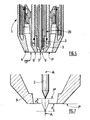
- FIGS. 1a and 1b schematize preparations of parts to be welded to form such tubes, namely a cylindrical or cylindroconic piece in edge-to-edge position on the Figure 1a , and a polygonal piece, for example octagonal, in welding position forming a 'V' on the figure 1b .
- the desired penetration (PE) must generally be at least 2.4 mm in order to obtain sufficient mechanical strength of the tube thus obtained, in particular when it is intended to be used as a support pole.
- Such welding is usually achieved by welding, namely high frequency welding or submerged arc welding (SA).
- SA submerged arc welding
- the welded tubes are most of the time subsequently coated by hot zinc galvanizing.
- the aesthetics of the coating is altered by the externally visible bead resulting from a welding AS and moreover by a difference in appearance of the zinc coating on the weld, due to the different metallurgical nature of the filler wire.
- JP-A-07.256463 teaches a plasma arc welding or TIG welding torch comprising an electrode located within the inner nozzle but capable of protruding beyond the peripheral rim of the inner nozzle so that the distance between the electrode and the workpiece is between 1 and 6 mm.
- the weld no longer has a bead or a difference in the composition of the molten metal, since no filler metal is necessary with these types of processes, which improves the aesthetics of the welding of the welded tube and subsequently galvanized thus obtained.
- the figure 2 shows a conventional configuration of the active part of one of the TIG torches used to perform such a multi-cathode welding under double gas flow.
- a TIG arc welding torch 1 comprising a tungsten electrode 2 with pointed active end, where the electric arc is formed.
- the electrode 2 is surrounded by an internal nozzle 3 and an external nozzle 4.
- the pointed active end 5 of the electrode always protrudes beyond the peripheral rim 6 of the internal nozzle 3, that is to say that the end 5 of the electrode 2 emerges from the nozzle internal 3 of a length D typically of the order of about 4 mm, as is disclosed in the document EP-A-1459830
- the first advantage of a plasma arc is that it is 'hotter' than a TIG arc and therefore achieves higher melting performance and therefore greater thickness.
- a pilot arc can be applied between the tungsten electrode and the nozzle.
- This arc is initially ignited by high voltage / high frequency spark, in the presence of the central gas which is typically argon, and this pilot arc is kept in operation before the priming of the main welding arc.
- the initiation of the main welding arc on the workpiece is done instantly, without the need for a high voltage / high frequency spark, at each welding start, which avoids the electromagnetic disturbances on the driving members of the welding machine. the machine.
- the central gas can be usefully replaced by another gas better adapted to the melting of carbon steel, such as the gas mixture argon / hydrogen type marketed by Air Liquide under the name NOXAL 4 TM.
- the end 7 of the electrode 2 is located inside the internal nozzle 3, which implies that the electric arc generated, during the welding, between the electrode and the or the parts to be welded is relatively long, that is to say typically more than 5 or 6 mm.
- the electromagnetic disturbances and thus the untimely deviations of arcs are all the more important that the intensity is high, so that as soon as the intensity of the main continuous welding current exceeds 320 amps, the arcs are not stable enough for industrial application, particularly for welding carbon steel tubes having a thickness of about 3 and 4 mm.
- the problem is to improve existing multi-electrode installations and arc welding processes so as to avoid or minimize cord blow-out phenomena and to substantially increase the welding speed, that is to say ie to propose an improved welding installation using torches having the advantages of plasma torches but not their disadvantages, which installation could allow the welding of the tubes intended to be used as poles or support poles.
- the solution of the invention is an arc welding apparatus comprising a plurality of arc welding torches as defined in claim 1.
- This installation comprises a plurality of torches, each comprising a tungsten electrode with a pointed end, an internal nozzle surrounding the electrode and an external nozzle surrounding said inner nozzle, the annular end edge of the inner nozzle and the tip of the electrode being substantially located in the same plane.
- the distance d between a first plane P perpendicular to the longitudinal axis of the electrode and passing at the level of the annular flange surface at the end of the internal nozzle, a second plane P ' passing through the pointed end of the electrode and which is parallel to the first plane P is such that: 0 ⁇ d ⁇ 1 mm, and the inner nozzle has an outlet orifice with a diameter of between 5.3 and 7 mm.
- the invention also relates to a method of electric arc welding of one or more metal parts, in particular the two longitudinal edges of a tube, in which an installation according to the invention is used.
- the solution of the invention is therefore based on a compromise between the two configurations of known torch ends, namely the “dual flux TIG” configuration, on the one hand, and the “plasma” configuration, on the other hand.
- the active end or tip 7 of the electrode 2 is not protruding as in a dual flux TIG torch ( Fig. 2 ), nor internal as in a plasma torch ( Fig. 3 ), but flush with the end of the centering gun serving as a nozzle or internal nozzle 3 of the torch.
- the end of the tip 7 of the electrode 2 is substantially located in the same plane P as the annular flange 6 located at the end of the internal nozzle 3, that is to say the annular flange 6 surrounding the outlet orifice 9 of the gas dispensed by the internal nozzle 3.
- an internal nozzle 3 is used, the outlet orifice 9 of which has a diameter of approximately 6 mm.
- the electrode 2 can, for its part, have a diameter of 4 mm.
- the inner nozzle 3 has an outlet diameter of between 5.3 and 7 mm.
- a first flow of non-oxidizing gas is distributed by the central nozzle 3, which flow comes into contact with the tungsten electrode, and a second gas stream, oxidizing, non-oxidizing, inert or reducing, is distributed by the outer nozzle peripherally or annularly at the first gas flow.
- the choice of gases is in a conventional manner, in particular depending on the nature of the material to be welded.
- the arcs are more stable than with a conventional plasma torch for which the orifice 9 generally has a diameter of 3 to 5 mm; the blisters disappear; higher intensities of about 10% on torches can be applied, that is, from 350 to 370 A, and lower arc voltages of about 10%, i.e. V; and the shape of the penetration of the melted zone makes it possible to decrease the sensitivity to its collapse, as schematized on the Figures 6a and 6b , for the same edge-to-edge preparation when welding a cylindrical tube.
- the welding tube has a thickness of 4 mm, is made of carbon steel of the same composition, is placed in edge-to-edge position (pre-tube of cylindrical shape).
- the distances between the torches that is to say between the arcs, must be the lowest possible, that is to say of the order of 60 mm.
- a fourth torch can be usefully used to re-merge the solder surface to improve the appearance.
- An intensity of 150 to 220 A at 25 to 30 V is sufficient.
- This fourth torch known as smoothing the weld, is placed at a distance greater than the others, that is to say about 120 to 200 mm behind the third torch, so as to allow sufficient cooling of the welded metal, before making undergo soldering a surface reflow by this fourth arc.
- a low contribution of metal of the same chemical composition as the base metal, in the form of melted filler wire under the welding electric arc, can also be useful, in order to fill a slight deficit of material according to the quality of the preparation edges of the workpiece.
- the torches used in the installation have a configuration "double flow", that is to say with central nozzle and peripheral nozzle, because one of the nozzles is used to create a pilot priming arc between the tungsten electrode and said nozzle, and thus obtain an immediate priming of the main welding arc.
Claims (11)
- Lichtbogenschweißanlage mit mehreren Lichtbogenschweißbrennern (1), die jeweils eine Elektrode (2) aus Wolfram mit einem spitz zulaufenden (7) Ende (5) aufweisen, dadurch gekennzeichnet, dass jeder Brenner eine innere Düse (3), welche die Elektrode (2) umgibt, und eine äußere Düse (4), welche die innere Düse (3) umgibt, aufweist, wobei der ringförmige Rand (6) des Endes der inneren Düse (3) und die Spitze (7) der Elektrode (5) sich im Wesentlichen in ein und derselben Ebene befinden, wobei der Abstand (d), der eine erste Ebene (P), die zur Längsachse der Elektrode (2) senkrecht ist und auf der Höhe der Oberseite des am Ende der inneren Düse (3) befindlichen ringförmigen Randes (6) verläuft, von einer zweiten Ebene (P') trennt, die durch das spitz zulaufende Ende (7) der Elektrode (2) verläuft und die parallel zu der ersten Ebene (P) und über oder unter dieser befindlich ist, derart ist, dass gilt: 0 ≤ d < 1 mm, und die innere Düse (3) eine Austrittsöffnung mit einem Durchmesser aufweist, der zwischen 5,3 und 7 mm liegt.
- Anlage nach Anspruch 1, dadurch gekennzeichnet, dass der Abstand (d) zwischen der ersten und der zweiten Ebene (P, P') derart ist, dass gilt: d < 0,5 mm.
- Anlage nach Anspruch 1 oder 2, dadurch gekennzeichnet, dass die innere Düse (3) eine Austrittsöffnung mit einem Durchmesser aufweist, der zwischen 5,7 und 6,5 mm liegt, vorzugsweise ungefähr bei 6 mm.
- Anlage nach einem der Ansprüche 1 bis 3, dadurch gekennzeichnet, dass sie 2 bis 5 aneinander gereihte Brenner (1) aufweist.
- Verfahren zum elektrischen Lichtbogenschweißen eines oder mehrerer Metallteile, insbesondere von zwei Längsrändern eines Rohres, bei welchem eine Anlage nach einem der Ansprüche 1 bis 4 eingesetzt wird.
- Verfahren nach Anspruch 5, dadurch gekennzeichnet, dass ein Schweißstrom mit einer Stromstärke, die zwischen 120 und 250 Ampere beträgt, an den letzten Schweißbrenner angelegt wird.
- Verfahren nach den Ansprüchen 5 oder 6, dadurch gekennzeichnet, dass die zwei Längsränder eines Rohres zusammengeschweißt werden, insbesondere eines zylindrischen oder polygonalen Rohres.
- Verfahren nach den Ansprüchen 5 bis 7, dadurch gekennzeichnet, dass eine Schweißung durchgeführt wird, bei welcher der Einbrand (PE) der Schweißnaht größer oder gleich 60% der Dicke (EP) des Teils oder der Teile ist, die zusammenzuschweißen sind.
- Verfahren nach den Ansprüchen 5 bis 8, dadurch gekennzeichnet, dass die Dicke des Teils oder der Teile, die zusammenzuschweißen sind, zwischen 2 und 6 mm beträgt, vorzugsweise zwischen 2,5 und 4 mm.
- Verfahren nach den Ansprüchen 5 bis 9, dadurch gekennzeichnet, dass das Teil oder die Teile, die zusammenzuschweißen sind, aus Kohlenstoffstahl bestehen.
- Verfahren nach den Ansprüchen 5 bis 10, dadurch gekennzeichnet, dass die Schweißgeschwindigkeit mindestens 2 m/min beträgt.
Applications Claiming Priority (1)
| Application Number | Priority Date | Filing Date | Title |
|---|---|---|---|
| FR0452567A FR2877597B1 (fr) | 2004-11-09 | 2004-11-09 | Torche de soudage a l'arc de type double flux adaptee au soudage de tubes |
Publications (2)
| Publication Number | Publication Date |
|---|---|
| EP1655096A1 EP1655096A1 (de) | 2006-05-10 |
| EP1655096B1 true EP1655096B1 (de) | 2008-04-23 |
Family
ID=34950274
Family Applications (1)
| Application Number | Title | Priority Date | Filing Date |
|---|---|---|---|
| EP05300842A Not-in-force EP1655096B1 (de) | 2004-11-09 | 2005-10-21 | Lichtbogenschweissanlage mit mehreren Brennern mit nichtabschmelzender Elektrode und Zweifach-Fluxschutz für Rohrschweissen, jeder brenner mit der in dem Plan der inneren Düse liegenden Elektrodespitze |
Country Status (5)
| Country | Link |
|---|---|
| EP (1) | EP1655096B1 (de) |
| AT (1) | ATE392977T1 (de) |
| DE (1) | DE602005006215T2 (de) |
| ES (1) | ES2306056T3 (de) |
| FR (1) | FR2877597B1 (de) |
Families Citing this family (3)
| Publication number | Priority date | Publication date | Assignee | Title |
|---|---|---|---|---|
| CN104289801A (zh) * | 2013-07-15 | 2015-01-21 | 昆山华焊科技有限公司 | 一种钨极可伸缩式焊枪 |
| CN107378209B (zh) * | 2017-08-22 | 2019-05-24 | 天津大学 | 一种压缩-自由复合大功率电弧喷嘴 |
| DE102017216440A1 (de) * | 2017-09-15 | 2019-03-21 | Kjellberg Stiftung | WIG-Brenner zum Schweißen, Löten oder Beschichten |
Family Cites Families (12)
| Publication number | Priority date | Publication date | Assignee | Title |
|---|---|---|---|---|
| US2806124A (en) * | 1955-07-26 | 1957-09-10 | Union Carbide Corp | Arc torch and process |
| GB866575A (en) * | 1958-01-06 | 1961-04-26 | Union Carbide Corp | Gas shielded arc cutting |
| US3575568A (en) * | 1967-06-08 | 1971-04-20 | Rikagaku Kenkyusho | Arc torch |
| SE387561B (sv) * | 1973-10-26 | 1976-09-13 | Fagersta Ab | Sett och anordning for svetsning med flera ljusbagar |
| GB1562014A (en) * | 1977-02-09 | 1980-03-05 | V N I Proektnokonstrukt I Tekh | Arc welding |
| DE3542984A1 (de) * | 1985-12-05 | 1987-06-11 | Stk Ges Fuer Schweisstechnik M | Verfahren und einrichtung zum teil- oder vollmechanisierten schutzgas-verbindungsschweissen |
| FI86038C (fi) * | 1991-02-25 | 1992-07-10 | Rotaweld Oy | Plasmabraennare. |
| JPH06277847A (ja) * | 1993-03-29 | 1994-10-04 | Japan Nuclear Fuel Co Ltd<Jnf> | ステンレス鋼系のtig溶接方法 |
| JPH07227673A (ja) * | 1994-02-17 | 1995-08-29 | Nippon Steel Corp | 高能率tig溶接法 |
| JP3437630B2 (ja) * | 1994-03-22 | 2003-08-18 | 日立ビアメカニクス株式会社 | 亜鉛めっき鋼板の溶接方法 |
| FR2766399B1 (fr) * | 1997-07-25 | 1999-09-03 | Soudure Autogene Francaise | Procede de fabrication de tubes metalliques |
| TW200510105A (en) * | 2003-03-19 | 2005-03-16 | Nippon Oxygen Co Ltd | TIG welding apparatus and TIG welding method |
-
2004
- 2004-11-09 FR FR0452567A patent/FR2877597B1/fr not_active Expired - Fee Related
-
2005
- 2005-10-21 EP EP05300842A patent/EP1655096B1/de not_active Not-in-force
- 2005-10-21 DE DE602005006215T patent/DE602005006215T2/de active Active
- 2005-10-21 ES ES05300842T patent/ES2306056T3/es active Active
- 2005-10-21 AT AT05300842T patent/ATE392977T1/de not_active IP Right Cessation
Also Published As
| Publication number | Publication date |
|---|---|
| EP1655096A1 (de) | 2006-05-10 |
| ES2306056T3 (es) | 2008-11-01 |
| ATE392977T1 (de) | 2008-05-15 |
| FR2877597B1 (fr) | 2008-04-25 |
| DE602005006215T2 (de) | 2009-06-18 |
| FR2877597A1 (fr) | 2006-05-12 |
| DE602005006215D1 (de) | 2008-06-05 |
Similar Documents
| Publication | Publication Date | Title |
|---|---|---|
| EP1736270B2 (de) | WIG-Schweiss- bzw, Lötverfahren mit Metallübertragung durch eine flüssigmetallbrücke | |
| EP2605880B1 (de) | Bogenschweissvorrichtung und -verfahren unter verwendung eines mig/mag-brenners in kombination mit einem wig-brenner | |
| EP2802435B1 (de) | Mig/wig oder mag/wig hybrid-schweissvorrichtung | |
| EP2051831A1 (de) | Wig-löt-schweissung mit metallübertragung in tropfenform mit gesteuerter frequenz | |
| FR2829414A1 (fr) | Procede de soudage hybride laser-arc avec ajustage des debits de gaz | |
| FR2876306A1 (fr) | Fil-electrode de soudage | |
| EP1655096B1 (de) | Lichtbogenschweissanlage mit mehreren Brennern mit nichtabschmelzender Elektrode und Zweifach-Fluxschutz für Rohrschweissen, jeder brenner mit der in dem Plan der inneren Düse liegenden Elektrodespitze | |
| FR2766399A1 (fr) | Procede de fabrication de tubes metalliques | |
| WO1999053734A1 (fr) | Torche et procede de coupage ou soudage a l'arc electrique | |
| EP2694243B1 (de) | Fülldraht zum schweissung von stahl mit hohem nickelgehalt | |
| EP1147692B1 (de) | Aus kupfer-legierung hergestelltes verschleissteil für lichtbogenbrenner | |
| FR3012759A3 (fr) | Systeme pour et procede de soudage et/ou de rechargement avec fil additionnel | |
| EP0924017B1 (de) | Vorrichtung und Verfahren zum Plasmalichtbogenschweissen mit variabeler Polarität | |
| EP1181126B1 (de) | Verfahren und anlage zum automatischen mehr-plasmaschweissen | |
| FR2941880A1 (fr) | Procede de soudage a l'arc sous double flux gazeux | |
| JP5086881B2 (ja) | 薄鋼板の高速ガスシールドアーク溶接方法 | |
| FR2807682A1 (fr) | Preparation et soudage mig ou mag de pieces tubulaires | |
| FR2829955A1 (fr) | Procede de soudage tig avec apport de fil et protection gazeuse adaptee | |
| JP6210093B2 (ja) | レーザ肉盛方法 | |
| EP2590772B1 (de) | Mig/mag-schweissen mit einem drehenden lichtbogen für c-stahl und ar/he/o2 gasmischung | |
| FR2975029A1 (fr) | Soudage mig/mag des aciers inoxydables avec arc rotatif et melange gazeux ar/he/co2 | |
| FR2781171A1 (fr) | Buse de soudage a l'arc electrique de diametre et d'epaisseur controles | |
| EP2248621B2 (de) | Verfahren zum Anfangen eines Lichtbogenschweissens mit Verspätung des Eintrittes in der gepulsten Phase | |
| EP1201345B1 (de) | Schweiss-Löt-TIG-Verfahren für verzinkte Stahlbleche | |
| FR2746046A1 (fr) | Procede de soudage tig avec fil fourre et fil fourre correspondant |
Legal Events
| Date | Code | Title | Description |
|---|---|---|---|
| PUAI | Public reference made under article 153(3) epc to a published international application that has entered the european phase |
Free format text: ORIGINAL CODE: 0009012 |
|
| AK | Designated contracting states |
Kind code of ref document: A1 Designated state(s): AT BE BG CH CY CZ DE DK EE ES FI FR GB GR HU IE IS IT LI LT LU LV MC NL PL PT RO SE SI SK TR |
|
| AX | Request for extension of the european patent |
Extension state: AL BA HR MK YU |
|
| 17P | Request for examination filed |
Effective date: 20061110 |
|
| 17Q | First examination report despatched |
Effective date: 20061208 |
|
| AKX | Designation fees paid |
Designated state(s): AT BE BG CH CY CZ DE DK EE ES FI FR GB GR HU IE IS IT LI LT LU LV MC NL PL PT RO SE SI SK TR |
|
| GRAP | Despatch of communication of intention to grant a patent |
Free format text: ORIGINAL CODE: EPIDOSNIGR1 |
|
| RTI1 | Title (correction) |
Free format text: INSTALLATION FOR ARC WELDING WITH SEVERAL TORCHES USING A NON-CONSUMABLE ELECTRODE AND DOUBLE PROTECTIVE FLUX FOR WELDING TUBES, EACH TORCH HAVING THE ELECTRODE TIP LOCATED IN TH |
|
| RAP1 | Party data changed (applicant data changed or rights of an application transferred) |
Owner name: AIR LIQUIDE WELDING FRANCE |
|
| GRAS | Grant fee paid |
Free format text: ORIGINAL CODE: EPIDOSNIGR3 |
|
| GRAA | (expected) grant |
Free format text: ORIGINAL CODE: 0009210 |
|
| AK | Designated contracting states |
Kind code of ref document: B1 Designated state(s): AT BE BG CH CY CZ DE DK EE ES FI FR GB GR HU IE IS IT LI LT LU LV MC NL PL PT RO SE SI SK TR |
|
| REG | Reference to a national code |
Ref country code: GB Ref legal event code: FG4D Free format text: NOT ENGLISH |
|
| REG | Reference to a national code |
Ref country code: CH Ref legal event code: EP |
|
| REF | Corresponds to: |
Ref document number: 602005006215 Country of ref document: DE Date of ref document: 20080605 Kind code of ref document: P |
|
| REG | Reference to a national code |
Ref country code: IE Ref legal event code: FG4D |
|
| PG25 | Lapsed in a contracting state [announced via postgrant information from national office to epo] |
Ref country code: SI Free format text: LAPSE BECAUSE OF FAILURE TO SUBMIT A TRANSLATION OF THE DESCRIPTION OR TO PAY THE FEE WITHIN THE PRESCRIBED TIME-LIMIT Effective date: 20080423 |
|
| NLV1 | Nl: lapsed or annulled due to failure to fulfill the requirements of art. 29p and 29m of the patents act | ||
| PG25 | Lapsed in a contracting state [announced via postgrant information from national office to epo] |
Ref country code: NL Free format text: LAPSE BECAUSE OF FAILURE TO SUBMIT A TRANSLATION OF THE DESCRIPTION OR TO PAY THE FEE WITHIN THE PRESCRIBED TIME-LIMIT Effective date: 20080423 Ref country code: FI Free format text: LAPSE BECAUSE OF FAILURE TO SUBMIT A TRANSLATION OF THE DESCRIPTION OR TO PAY THE FEE WITHIN THE PRESCRIBED TIME-LIMIT Effective date: 20080423 Ref country code: PT Free format text: LAPSE BECAUSE OF FAILURE TO SUBMIT A TRANSLATION OF THE DESCRIPTION OR TO PAY THE FEE WITHIN THE PRESCRIBED TIME-LIMIT Effective date: 20080923 Ref country code: BG Free format text: LAPSE BECAUSE OF FAILURE TO SUBMIT A TRANSLATION OF THE DESCRIPTION OR TO PAY THE FEE WITHIN THE PRESCRIBED TIME-LIMIT Effective date: 20080723 |
|
| REG | Reference to a national code |
Ref country code: ES Ref legal event code: FG2A Ref document number: 2306056 Country of ref document: ES Kind code of ref document: T3 |
|
| PG25 | Lapsed in a contracting state [announced via postgrant information from national office to epo] |
Ref country code: AT Free format text: LAPSE BECAUSE OF FAILURE TO SUBMIT A TRANSLATION OF THE DESCRIPTION OR TO PAY THE FEE WITHIN THE PRESCRIBED TIME-LIMIT Effective date: 20080423 Ref country code: PL Free format text: LAPSE BECAUSE OF FAILURE TO SUBMIT A TRANSLATION OF THE DESCRIPTION OR TO PAY THE FEE WITHIN THE PRESCRIBED TIME-LIMIT Effective date: 20080423 Ref country code: LV Free format text: LAPSE BECAUSE OF FAILURE TO SUBMIT A TRANSLATION OF THE DESCRIPTION OR TO PAY THE FEE WITHIN THE PRESCRIBED TIME-LIMIT Effective date: 20080423 |
|
| PG25 | Lapsed in a contracting state [announced via postgrant information from national office to epo] |
Ref country code: IS Free format text: LAPSE BECAUSE OF FAILURE TO SUBMIT A TRANSLATION OF THE DESCRIPTION OR TO PAY THE FEE WITHIN THE PRESCRIBED TIME-LIMIT Effective date: 20080823 |
|
| PG25 | Lapsed in a contracting state [announced via postgrant information from national office to epo] |
Ref country code: DK Free format text: LAPSE BECAUSE OF FAILURE TO SUBMIT A TRANSLATION OF THE DESCRIPTION OR TO PAY THE FEE WITHIN THE PRESCRIBED TIME-LIMIT Effective date: 20080423 Ref country code: SE Free format text: LAPSE BECAUSE OF FAILURE TO SUBMIT A TRANSLATION OF THE DESCRIPTION OR TO PAY THE FEE WITHIN THE PRESCRIBED TIME-LIMIT Effective date: 20080723 Ref country code: LT Free format text: LAPSE BECAUSE OF FAILURE TO SUBMIT A TRANSLATION OF THE DESCRIPTION OR TO PAY THE FEE WITHIN THE PRESCRIBED TIME-LIMIT Effective date: 20080423 Ref country code: CZ Free format text: LAPSE BECAUSE OF FAILURE TO SUBMIT A TRANSLATION OF THE DESCRIPTION OR TO PAY THE FEE WITHIN THE PRESCRIBED TIME-LIMIT Effective date: 20080423 |
|
| PG25 | Lapsed in a contracting state [announced via postgrant information from national office to epo] |
Ref country code: RO Free format text: LAPSE BECAUSE OF FAILURE TO SUBMIT A TRANSLATION OF THE DESCRIPTION OR TO PAY THE FEE WITHIN THE PRESCRIBED TIME-LIMIT Effective date: 20080423 Ref country code: SK Free format text: LAPSE BECAUSE OF FAILURE TO SUBMIT A TRANSLATION OF THE DESCRIPTION OR TO PAY THE FEE WITHIN THE PRESCRIBED TIME-LIMIT Effective date: 20080423 |
|
| PLBE | No opposition filed within time limit |
Free format text: ORIGINAL CODE: 0009261 |
|
| STAA | Information on the status of an ep patent application or granted ep patent |
Free format text: STATUS: NO OPPOSITION FILED WITHIN TIME LIMIT |
|
| 26N | No opposition filed |
Effective date: 20090126 |
|
| BERE | Be: lapsed |
Owner name: AIR LIQUIDE WELDING FRANCE Effective date: 20081031 |
|
| PG25 | Lapsed in a contracting state [announced via postgrant information from national office to epo] |
Ref country code: EE Free format text: LAPSE BECAUSE OF FAILURE TO SUBMIT A TRANSLATION OF THE DESCRIPTION OR TO PAY THE FEE WITHIN THE PRESCRIBED TIME-LIMIT Effective date: 20080423 |
|
| PG25 | Lapsed in a contracting state [announced via postgrant information from national office to epo] |
Ref country code: MC Free format text: LAPSE BECAUSE OF NON-PAYMENT OF DUE FEES Effective date: 20081031 |
|
| PG25 | Lapsed in a contracting state [announced via postgrant information from national office to epo] |
Ref country code: BE Free format text: LAPSE BECAUSE OF NON-PAYMENT OF DUE FEES Effective date: 20081031 |
|
| PGFP | Annual fee paid to national office [announced via postgrant information from national office to epo] |
Ref country code: IE Payment date: 20091028 Year of fee payment: 5 |
|
| PGFP | Annual fee paid to national office [announced via postgrant information from national office to epo] |
Ref country code: GB Payment date: 20091022 Year of fee payment: 5 |
|
| REG | Reference to a national code |
Ref country code: CH Ref legal event code: PL |
|
| PG25 | Lapsed in a contracting state [announced via postgrant information from national office to epo] |
Ref country code: LU Free format text: LAPSE BECAUSE OF NON-PAYMENT OF DUE FEES Effective date: 20081021 Ref country code: HU Free format text: LAPSE BECAUSE OF FAILURE TO SUBMIT A TRANSLATION OF THE DESCRIPTION OR TO PAY THE FEE WITHIN THE PRESCRIBED TIME-LIMIT Effective date: 20081024 Ref country code: CY Free format text: LAPSE BECAUSE OF FAILURE TO SUBMIT A TRANSLATION OF THE DESCRIPTION OR TO PAY THE FEE WITHIN THE PRESCRIBED TIME-LIMIT Effective date: 20080423 |
|
| PG25 | Lapsed in a contracting state [announced via postgrant information from national office to epo] |
Ref country code: TR Free format text: LAPSE BECAUSE OF FAILURE TO SUBMIT A TRANSLATION OF THE DESCRIPTION OR TO PAY THE FEE WITHIN THE PRESCRIBED TIME-LIMIT Effective date: 20080423 |
|
| PG25 | Lapsed in a contracting state [announced via postgrant information from national office to epo] |
Ref country code: GR Free format text: LAPSE BECAUSE OF FAILURE TO SUBMIT A TRANSLATION OF THE DESCRIPTION OR TO PAY THE FEE WITHIN THE PRESCRIBED TIME-LIMIT Effective date: 20080724 Ref country code: CH Free format text: LAPSE BECAUSE OF NON-PAYMENT OF DUE FEES Effective date: 20091031 Ref country code: LI Free format text: LAPSE BECAUSE OF NON-PAYMENT OF DUE FEES Effective date: 20091031 |
|
| PGFP | Annual fee paid to national office [announced via postgrant information from national office to epo] |
Ref country code: DE Payment date: 20101022 Year of fee payment: 6 |
|
| PGFP | Annual fee paid to national office [announced via postgrant information from national office to epo] |
Ref country code: IT Payment date: 20101027 Year of fee payment: 6 |
|
| GBPC | Gb: european patent ceased through non-payment of renewal fee |
Effective date: 20101021 |
|
| REG | Reference to a national code |
Ref country code: IE Ref legal event code: MM4A |
|
| PG25 | Lapsed in a contracting state [announced via postgrant information from national office to epo] |
Ref country code: GB Free format text: LAPSE BECAUSE OF NON-PAYMENT OF DUE FEES Effective date: 20101021 |
|
| PG25 | Lapsed in a contracting state [announced via postgrant information from national office to epo] |
Ref country code: IE Free format text: LAPSE BECAUSE OF NON-PAYMENT OF DUE FEES Effective date: 20101021 |
|
| PGFP | Annual fee paid to national office [announced via postgrant information from national office to epo] |
Ref country code: FR Payment date: 20111103 Year of fee payment: 7 Ref country code: ES Payment date: 20111021 Year of fee payment: 7 |
|
| REG | Reference to a national code |
Ref country code: FR Ref legal event code: ST Effective date: 20130628 |
|
| PG25 | Lapsed in a contracting state [announced via postgrant information from national office to epo] |
Ref country code: DE Free format text: LAPSE BECAUSE OF NON-PAYMENT OF DUE FEES Effective date: 20130501 |
|
| REG | Reference to a national code |
Ref country code: DE Ref legal event code: R119 Ref document number: 602005006215 Country of ref document: DE Effective date: 20130501 |
|
| PG25 | Lapsed in a contracting state [announced via postgrant information from national office to epo] |
Ref country code: IT Free format text: LAPSE BECAUSE OF NON-PAYMENT OF DUE FEES Effective date: 20121021 Ref country code: FR Free format text: LAPSE BECAUSE OF NON-PAYMENT OF DUE FEES Effective date: 20121031 |
|
| REG | Reference to a national code |
Ref country code: ES Ref legal event code: FD2A Effective date: 20140116 |
|
| PG25 | Lapsed in a contracting state [announced via postgrant information from national office to epo] |
Ref country code: ES Free format text: LAPSE BECAUSE OF NON-PAYMENT OF DUE FEES Effective date: 20121022 |