EP1655096B1 - Installation for arc welding with several torches using a non-consumable electrode and double protective flux for welding tubes, each torch having the electrode tip located in the plane of the inner nozzle - Google Patents
Installation for arc welding with several torches using a non-consumable electrode and double protective flux for welding tubes, each torch having the electrode tip located in the plane of the inner nozzle Download PDFInfo
- Publication number
- EP1655096B1 EP1655096B1 EP05300842A EP05300842A EP1655096B1 EP 1655096 B1 EP1655096 B1 EP 1655096B1 EP 05300842 A EP05300842 A EP 05300842A EP 05300842 A EP05300842 A EP 05300842A EP 1655096 B1 EP1655096 B1 EP 1655096B1
- Authority
- EP
- European Patent Office
- Prior art keywords
- welding
- electrode
- plane
- torch
- inner nozzle
- Prior art date
- Legal status (The legal status is an assumption and is not a legal conclusion. Google has not performed a legal analysis and makes no representation as to the accuracy of the status listed.)
- Not-in-force
Links
Images


Classifications
-
- B—PERFORMING OPERATIONS; TRANSPORTING
- B23—MACHINE TOOLS; METAL-WORKING NOT OTHERWISE PROVIDED FOR
- B23K—SOLDERING OR UNSOLDERING; WELDING; CLADDING OR PLATING BY SOLDERING OR WELDING; CUTTING BY APPLYING HEAT LOCALLY, e.g. FLAME CUTTING; WORKING BY LASER BEAM
- B23K9/00—Arc welding or cutting
- B23K9/16—Arc welding or cutting making use of shielding gas
- B23K9/167—Arc welding or cutting making use of shielding gas and of a non-consumable electrode
- B23K9/1675—Arc welding or cutting making use of shielding gas and of a non-consumable electrode making use of several electrodes
-
- H—ELECTRICITY
- H05—ELECTRIC TECHNIQUES NOT OTHERWISE PROVIDED FOR
- H05H—PLASMA TECHNIQUE; PRODUCTION OF ACCELERATED ELECTRICALLY-CHARGED PARTICLES OR OF NEUTRONS; PRODUCTION OR ACCELERATION OF NEUTRAL MOLECULAR OR ATOMIC BEAMS
- H05H1/00—Generating plasma; Handling plasma
- H05H1/24—Generating plasma
- H05H1/26—Plasma torches
- H05H1/32—Plasma torches using an arc
- H05H1/34—Details, e.g. electrodes, nozzles
-
- B—PERFORMING OPERATIONS; TRANSPORTING
- B23—MACHINE TOOLS; METAL-WORKING NOT OTHERWISE PROVIDED FOR
- B23K—SOLDERING OR UNSOLDERING; WELDING; CLADDING OR PLATING BY SOLDERING OR WELDING; CUTTING BY APPLYING HEAT LOCALLY, e.g. FLAME CUTTING; WORKING BY LASER BEAM
- B23K10/00—Welding or cutting by means of a plasma
- B23K10/02—Plasma welding
-
- B—PERFORMING OPERATIONS; TRANSPORTING
- B23—MACHINE TOOLS; METAL-WORKING NOT OTHERWISE PROVIDED FOR
- B23K—SOLDERING OR UNSOLDERING; WELDING; CLADDING OR PLATING BY SOLDERING OR WELDING; CUTTING BY APPLYING HEAT LOCALLY, e.g. FLAME CUTTING; WORKING BY LASER BEAM
- B23K9/00—Arc welding or cutting
- B23K9/02—Seam welding; Backing means; Inserts
- B23K9/025—Seam welding; Backing means; Inserts for rectilinear seams
- B23K9/0253—Seam welding; Backing means; Inserts for rectilinear seams for the longitudinal seam of tubes
Definitions
- An arc welding apparatus comprising a plurality of dual flux arc welding torches comprising a tungsten electrode having a pointed end located in or approximately in the same plane as that formed by the peripheral rim end of the inner nozzle, and its use for longitudinal welding tubes or the like.
- the thicknesses to be welded are generally order of 2.5 to 4 mm, at the joint plane, that is to say where the two edges to be welded meet and must be assembled by welding.
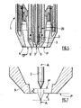
- FIGS. 1a and 1b schematize preparations of parts to be welded to form such tubes, namely a cylindrical or cylindroconic piece in edge-to-edge position on the Figure 1a , and a polygonal piece, for example octagonal, in welding position forming a 'V' on the figure 1b .
- the desired penetration (PE) must generally be at least 2.4 mm in order to obtain sufficient mechanical strength of the tube thus obtained, in particular when it is intended to be used as a support pole.
- Such welding is usually achieved by welding, namely high frequency welding or submerged arc welding (SA).
- SA submerged arc welding
- the welded tubes are most of the time subsequently coated by hot zinc galvanizing.
- the aesthetics of the coating is altered by the externally visible bead resulting from a welding AS and moreover by a difference in appearance of the zinc coating on the weld, due to the different metallurgical nature of the filler wire.
- JP-A-07.256463 teaches a plasma arc welding or TIG welding torch comprising an electrode located within the inner nozzle but capable of protruding beyond the peripheral rim of the inner nozzle so that the distance between the electrode and the workpiece is between 1 and 6 mm.
- the weld no longer has a bead or a difference in the composition of the molten metal, since no filler metal is necessary with these types of processes, which improves the aesthetics of the welding of the welded tube and subsequently galvanized thus obtained.
- the figure 2 shows a conventional configuration of the active part of one of the TIG torches used to perform such a multi-cathode welding under double gas flow.
- a TIG arc welding torch 1 comprising a tungsten electrode 2 with pointed active end, where the electric arc is formed.
- the electrode 2 is surrounded by an internal nozzle 3 and an external nozzle 4.
- the pointed active end 5 of the electrode always protrudes beyond the peripheral rim 6 of the internal nozzle 3, that is to say that the end 5 of the electrode 2 emerges from the nozzle internal 3 of a length D typically of the order of about 4 mm, as is disclosed in the document EP-A-1459830
- the first advantage of a plasma arc is that it is 'hotter' than a TIG arc and therefore achieves higher melting performance and therefore greater thickness.
- a pilot arc can be applied between the tungsten electrode and the nozzle.
- This arc is initially ignited by high voltage / high frequency spark, in the presence of the central gas which is typically argon, and this pilot arc is kept in operation before the priming of the main welding arc.
- the initiation of the main welding arc on the workpiece is done instantly, without the need for a high voltage / high frequency spark, at each welding start, which avoids the electromagnetic disturbances on the driving members of the welding machine. the machine.
- the central gas can be usefully replaced by another gas better adapted to the melting of carbon steel, such as the gas mixture argon / hydrogen type marketed by Air Liquide under the name NOXAL 4 TM.
- the end 7 of the electrode 2 is located inside the internal nozzle 3, which implies that the electric arc generated, during the welding, between the electrode and the or the parts to be welded is relatively long, that is to say typically more than 5 or 6 mm.
- the electromagnetic disturbances and thus the untimely deviations of arcs are all the more important that the intensity is high, so that as soon as the intensity of the main continuous welding current exceeds 320 amps, the arcs are not stable enough for industrial application, particularly for welding carbon steel tubes having a thickness of about 3 and 4 mm.
- the problem is to improve existing multi-electrode installations and arc welding processes so as to avoid or minimize cord blow-out phenomena and to substantially increase the welding speed, that is to say ie to propose an improved welding installation using torches having the advantages of plasma torches but not their disadvantages, which installation could allow the welding of the tubes intended to be used as poles or support poles.
- the solution of the invention is an arc welding apparatus comprising a plurality of arc welding torches as defined in claim 1.
- This installation comprises a plurality of torches, each comprising a tungsten electrode with a pointed end, an internal nozzle surrounding the electrode and an external nozzle surrounding said inner nozzle, the annular end edge of the inner nozzle and the tip of the electrode being substantially located in the same plane.
- the distance d between a first plane P perpendicular to the longitudinal axis of the electrode and passing at the level of the annular flange surface at the end of the internal nozzle, a second plane P ' passing through the pointed end of the electrode and which is parallel to the first plane P is such that: 0 ⁇ d ⁇ 1 mm, and the inner nozzle has an outlet orifice with a diameter of between 5.3 and 7 mm.
- the invention also relates to a method of electric arc welding of one or more metal parts, in particular the two longitudinal edges of a tube, in which an installation according to the invention is used.
- the solution of the invention is therefore based on a compromise between the two configurations of known torch ends, namely the “dual flux TIG” configuration, on the one hand, and the “plasma” configuration, on the other hand.
- the active end or tip 7 of the electrode 2 is not protruding as in a dual flux TIG torch ( Fig. 2 ), nor internal as in a plasma torch ( Fig. 3 ), but flush with the end of the centering gun serving as a nozzle or internal nozzle 3 of the torch.
- the end of the tip 7 of the electrode 2 is substantially located in the same plane P as the annular flange 6 located at the end of the internal nozzle 3, that is to say the annular flange 6 surrounding the outlet orifice 9 of the gas dispensed by the internal nozzle 3.
- an internal nozzle 3 is used, the outlet orifice 9 of which has a diameter of approximately 6 mm.
- the electrode 2 can, for its part, have a diameter of 4 mm.
- the inner nozzle 3 has an outlet diameter of between 5.3 and 7 mm.
- a first flow of non-oxidizing gas is distributed by the central nozzle 3, which flow comes into contact with the tungsten electrode, and a second gas stream, oxidizing, non-oxidizing, inert or reducing, is distributed by the outer nozzle peripherally or annularly at the first gas flow.
- the choice of gases is in a conventional manner, in particular depending on the nature of the material to be welded.
- the arcs are more stable than with a conventional plasma torch for which the orifice 9 generally has a diameter of 3 to 5 mm; the blisters disappear; higher intensities of about 10% on torches can be applied, that is, from 350 to 370 A, and lower arc voltages of about 10%, i.e. V; and the shape of the penetration of the melted zone makes it possible to decrease the sensitivity to its collapse, as schematized on the Figures 6a and 6b , for the same edge-to-edge preparation when welding a cylindrical tube.
- the welding tube has a thickness of 4 mm, is made of carbon steel of the same composition, is placed in edge-to-edge position (pre-tube of cylindrical shape).
- the distances between the torches that is to say between the arcs, must be the lowest possible, that is to say of the order of 60 mm.
- a fourth torch can be usefully used to re-merge the solder surface to improve the appearance.
- An intensity of 150 to 220 A at 25 to 30 V is sufficient.
- This fourth torch known as smoothing the weld, is placed at a distance greater than the others, that is to say about 120 to 200 mm behind the third torch, so as to allow sufficient cooling of the welded metal, before making undergo soldering a surface reflow by this fourth arc.
- a low contribution of metal of the same chemical composition as the base metal, in the form of melted filler wire under the welding electric arc, can also be useful, in order to fill a slight deficit of material according to the quality of the preparation edges of the workpiece.
- the torches used in the installation have a configuration "double flow", that is to say with central nozzle and peripheral nozzle, because one of the nozzles is used to create a pilot priming arc between the tungsten electrode and said nozzle, and thus obtain an immediate priming of the main welding arc.
Abstract
Description
L'invention concerne une installation de soudage à l'arc comprenant plusieurs torches de soudage à l'arc à double flux comprenant une électrode en tungstène dont l'extrémité pointue se situe dans ou approximativement dans le même plan que celui formé par le rebord périphérique d'extrémité de la buse interne, et son utilisation pour le soudage longitudinal de tubes ou similaires.An arc welding apparatus comprising a plurality of dual flux arc welding torches comprising a tungsten electrode having a pointed end located in or approximately in the same plane as that formed by the peripheral rim end of the inner nozzle, and its use for longitudinal welding tubes or the like.
Lors de la réalisation de soudures longitudinales de tubes en acier au carbone ou en acier inoxydable, en particulier de tubes destinés à être utilisés comme mâts ou poteaux notamment pour l'éclairage qui sont appelés « candélabres », les épaisseurs à souder sont généralement de l'ordre de 2.5 à 4 mm, au niveau du plan de joint, c'est-à-dire là où les deux bords à souder se rejoignent et doivent être assemblés par soudage.When producing longitudinal welds of carbon steel or stainless steel tubes, in particular tubes intended to be used as masts or columns, especially for lighting, which are called "candelabra", the thicknesses to be welded are generally order of 2.5 to 4 mm, at the joint plane, that is to say where the two edges to be welded meet and must be assembled by welding.
Les
Comme illustré sur ces
En effet, le rapport PE/EP de la pénétration PE à l'épaisseur EP qui est couramment demandé pour répondre aux contraintes d'utilisation doit être égal ou supérieur à 60% (soit 2.4 mm/4 mm =60 %).In fact, the PE / EP ratio of the PE penetration to the EP thickness which is currently required to meet the operating constraints must be equal to or greater than 60% (ie 2.4 mm / 4 mm = 60%).
Un tel soudage est habituellement obtenu par soudage, à savoir le soudage à haute fréquence ou par soudage à l'arc submergé (AS). Or, ces procédés présentent des inconvénients.Such welding is usually achieved by welding, namely high frequency welding or submerged arc welding (SA). However, these methods have disadvantages.
Ainsi, le procédé de soudage AS rend obligatoire l'utilisation d'un métal d'apport et de flux de soudage, ce qui n'est pas pratique au plan industriel.Thus, the AS welding process requires the use of a filler metal and welding flux, which is not practical industrially.
Les vitesses atteintes industriellement avec un procédé AS sont de l'ordre de 2 m/mm pour des épaisseurs de tube de 4 mm en bord à bord, ce qui est compatible avec des cadences de production élevées, alors que celles pouvant être atteintes en soudage haute fréquence soient très supérieures aux précédentes mais la mise en oeuvre de ce procédé est très onéreuse, donc peu répandue dans l'industrie.The speeds achieved industrially with a process AS are of the order of 2 m / mm for tube thicknesses of 4 mm edge to edge, which is compatible with high production rates, while those that can be achieved in high frequency welding are much higher than the previous but the implementation of this process is very expensive, so not widespread in the industry.
Par ailleurs, les tubes soudés sont la plupart du temps subséquemment revêtus par galvanisation au zinc à chaud.Furthermore, the welded tubes are most of the time subsequently coated by hot zinc galvanizing.
Or, l'esthétique du revêtement est altérée par le bourrelet visible extérieurement résultant d'un soudage AS et de surcroît par une différence d'aspect du revêtement de zinc sur la soudure, du fait de la nature métallurgique différente du fil d'apport.However, the aesthetics of the coating is altered by the externally visible bead resulting from a welding AS and moreover by a difference in appearance of the zinc coating on the weld, due to the different metallurgical nature of the filler wire.
Pour pallier ces inconvénients, il a été déjà proposé de souder de tels assemblages en mettant en oeuvre des procédés de soudage à l'arc plasma ou de soudage TIG (pour Tungsten Inert Gas).To overcome these drawbacks, it has already been proposed to weld such assemblies using plasma arc welding or TIG (Tungsten Inert Gas) welding processes.
Le document
Par ailleurs, le document
Dans ce cas, la soudure ne présente plus de bourrelet, ni de différence de composition du métal fondu puisque aucun métal d'apport n'est nécessaire avec ces types de procédés, ce qui améliore l'esthétique de la soudure du tube soudé et subséquemment galvanisé ainsi obtenu.In this case, the weld no longer has a bead or a difference in the composition of the molten metal, since no filler metal is necessary with these types of processes, which improves the aesthetics of the welding of the welded tube and subsequently galvanized thus obtained.
Cependant, le soudage à l'arc, qu 'il soit plasma ou TIG, est un procédé lent lorsqu'il est utilisé avec une seule torche de soudage puisque des vitesses maximales de l'ordre de seulement 10 à 30 cm/min peuvent être atteintes, ce qui est souvent nettement insuffisant au plan Industriel.However, arc welding, whether plasma or TIG, is a slow process when used with a single welding torch since maximum speeds of the order of only 10 to 30 cm / min can be affected, which is often clearly insufficient on the industrial level.
Une amélioration notable a été proposée, laquelle est basée sur un soudage TIG multi-cathodes, c'est-à-dire mettant en oeuvre plusieurs arcs électriques alignés selon le plan de à réaliser de sorte que chaque zone de la soudure soit soumise successivement aux différents arcs électriques. Ce type de soudage est enseigné dans le document
Ainsi, un procédé TIG multi-cathodes avec double flux de gaz de protection a déjà été appliqué pour opérer un soudage à grande vitesse de tube en acier inoxydable ayant des épaisseurs compris entre environ 1 et 2 mm.Thus, a multi-cathode TIG process with double shielding gas flow has already been applied to perform high speed welding of stainless steel tube having thicknesses of between about 1 and 2 mm.
La
Afin d'améliorer ce procédé multi-électrodes, Il a été proposé de remplacer les arcs TIG par des arcs plasma. En effet, le soudage à l'arc plasma présente plusieurs avantages par rapport à un soudage à l'arc TIG.In order to improve this multi-electrode process, it has been proposed to replace TIG arches by plasma arcs. Indeed, plasma arc welding has several advantages over TIG arc welding.
Le premier avantage d'un arc plasma est qu'il est plus 'chaud' qu'un arc TIG et qu'il permet donc d'atteindre des performances de fusion supérieures et donc d'épaisseurs plus importantes.The first advantage of a plasma arc is that it is 'hotter' than a TIG arc and therefore achieves higher melting performance and therefore greater thickness.
Un autre avantage important, comme représenté en
Un autre avantage encore d'une torche plasma est que l'on peut appliquer un arc pilote entre l'électrode en tungstène et la tuyère. Cet arc est amorcé au départ par étincelle haute tension/haute fréquence, en présence du gaz central qui est typiquement de l'argon, et cet arc pilote est maintenu en fonctionnement avant l'amorçage de l'arc principal de soudage. Ainsi, l'amorçage de l'arc principal de soudage sur la pièce à souder se fait instantanément, sans nécessiter d'étincelle haute tension/haute fréquence, à chaque début de soudure, ce qui évite les perturbations électromagnétiques sur les organes de pilotage de la machine. Ensuite, juste après amorçage de l'arc principal, et pendant le soudage, le gaz central peut être utilement remplacé par un autre gaz mieux adapté à la fusion de l'acier au carbone, comme par exemple le mélange gazeux de type argon/hydrogène commercialisé par L'Air Liquide sous la dénomination NOXAL 4™.Yet another advantage of a plasma torch is that a pilot arc can be applied between the tungsten electrode and the nozzle. This arc is initially ignited by high voltage / high frequency spark, in the presence of the central gas which is typically argon, and this pilot arc is kept in operation before the priming of the main welding arc. Thus, the initiation of the main welding arc on the workpiece is done instantly, without the need for a high voltage / high frequency spark, at each welding start, which avoids the electromagnetic disturbances on the driving members of the welding machine. the machine. Then, just after initiation of the main arc, and during welding, the central gas can be usefully replaced by another gas better adapted to the melting of carbon steel, such as the gas mixture argon / hydrogen type marketed by Air Liquide under the name NOXAL 4 ™.
De façon générale, la mise en oeuvre simultanée de plusieurs arcs électriques, avec des torches TIG ou plasma, permet d'améliorer les performances de soudage, notamment la vitesse de soudage et la qualité esthétique du cordon, étant donné que :
- une torche permet de préchauffer le métal et de lui faire subir une fusion partielle en surface.
- une autre torche permet de terminer la fusion et d'assurer la pénétration de soudage recherchée.
- une torche supplémentaire, dite torche de lissage, peut éventuellement être ajoutée à la suite des deux autres pour re-fusionner, mais en surface seulement, la surface visible du cordon pour améliorer l'aspect de la zone fondue.
- a torch makes it possible to preheat the metal and to subject it to partial surface melting.
- another torch makes it possible to complete the fusion and to ensure the desired welding penetration.
- an additional torch, called a smoothing torch, may optionally be added after the other two to re-fuse, but only on the surface, the visible surface of the bead to improve the appearance of the melted zone.
Toutefois, en pratique, il est apparu des difficultés dues aux déviations d'arcs causées par des interactions entre eux des arcs électriques mis en oeuvre lors du soudage avec une telle installation multi-électrodes.However, in practice, difficulties have arisen due to the deviations of arcs caused by the interactions between them of the electric arcs used during welding with such a multi-electrode installation.
Pour les résoudre, il a été proposé de faire circuler, d'une manière particulière, le courant électrique de retour de chaque arc dans le métal du tube, c'est-à-dire en disposant des frotteurs ou prises de masses derrière chaque torche de soudage, comme illustré sur la
Comme on le voit sur la
Or, on comprend aisément que plus l'arc est long, plus les phénomènes de déviation d'arcs susmentionnés perturbent la stabilité des arcs.Now, it is easy to understand that the longer the arc, the more the deflection phenomena of the aforementioned arcs disturb the stability of the arcs.
Les perturbations électromagnétiques et donc les déviations intempestives d'arcs sont d'autant plus importantes que l'intensité est élevée, de sorte que, dès que l'intensité du courant continu principal de soudage dépasse 320 ampères, les arcs ne sont plus suffisamment stables pour une application industrielle, en particulier pour le soudage des tubes en acier au carbone ayant une épaisseur de l'ordre 3 et 4 mm.The electromagnetic disturbances and thus the untimely deviations of arcs are all the more important that the intensity is high, so that as soon as the intensity of the main continuous welding current exceeds 320 amps, the arcs are not stable enough for industrial application, particularly for welding carbon steel tubes having a thickness of about 3 and 4 mm.
Parce que l'on ne peut pas dépasser facilement l'intensité de soudage de 320 ampères, les vitesses de soudage sont donc limitées par le procédé lui même autour de 1.5 à 1.7 m/mm pour des tubes d'épaisseur 4 mm, lorsqu'on souhaite une pénétration de soudure d'environ 2.4 à 2.5 mm.Because we can not easily exceed the welding current of 320 amps, the welding speeds are limited by the process itself. even around 1.5 to 1.7 m / mm for tubes with a thickness of 4 mm, when a welding penetration of about 2.4 to 2.5 mm is desired.
On constate par ailleurs l'apparition de soufflures en surface de cordon qui sont très préjudiciables à l'esthétique de la soudure et à la tenue mécanique de l'assemblage. Ces défauts sont probablement imputables à une insuffisante protection gazeuse du bain de fusion qui est très allongé, de l'ordre de plusieurs cm derrière la dernière torche, associée à un « affouillement » du bain de métal fondu, sous la pression combinée de l'arc électrique et du gaz plasmagène, lesquels font remonter et surgir les impuretés du métal, et les oxydes métalliques à haute température.There is also the appearance of blows on the surface of the cord which are very detrimental to the aesthetics of the weld and the mechanical strength of the assembly. These defects are probably attributable to an insufficient gas protection of the melt which is very elongated, of the order of several cm behind the last torch, associated with a "scour" of the bath of molten metal, under the combined pressure of the electric arc and plasma gas, which bring up and arise the impurities of the metal, and the metal oxides at high temperature.
Le problème qui se pose est d'améliorer les installations multi-électrodes et procédés de soudage à l'arc existants de manière à éviter ou minimiser les phénomènes de soufflures du cordon et d'augmenter sensiblement la vitesse de soudage, c'est-à-dire de proposer une installation de soudage améliorée mettant en oeuvre des torches présentant les avantages des torches à plasma mais pas leurs inconvénients, laquelle installation puisse permettre le soudage des tubes destinés à être utilisés en tant que poteaux ou mâts-supports.The problem is to improve existing multi-electrode installations and arc welding processes so as to avoid or minimize cord blow-out phenomena and to substantially increase the welding speed, that is to say ie to propose an improved welding installation using torches having the advantages of plasma torches but not their disadvantages, which installation could allow the welding of the tubes intended to be used as poles or support poles.
La solution de l'invention est une installation de soudage à l'arc comprenant plusieurs torches de soudage à l'arc telles que définie dans la revendication 1. Cette installation comprend plusieurs torches, chacune comprenant chacune une électrode en tungstène avec une extrémité pointue, une tuyère interne entourant l'électrode et une tuyère externe entourant ladite tuyère interne, le rebord annulaire d'extrémité de la tuyère interne et la pointe de l'électrode étant sensiblement situés dans un même plan.The solution of the invention is an arc welding apparatus comprising a plurality of arc welding torches as defined in claim 1. This installation comprises a plurality of torches, each comprising a tungsten electrode with a pointed end, an internal nozzle surrounding the electrode and an external nozzle surrounding said inner nozzle, the annular end edge of the inner nozzle and the tip of the electrode being substantially located in the same plane.
Selon l'invention, la distance d séparant un premier plan P perpendiculaire à l'axe longitudinal de l'électrode et passant au niveau de la surface du rebord annulaire situé à l'extrémité de la tuyère interne, d'un second plan P' passant par l'extrémité pointue de l'électrode et qui est parallèle au premier plan P est telle que : 0 ≤ d < 1 mm, et la tuyère interne a un orifice de sortie de diamètre compris entre 5.3 et 7 mm.According to the invention, the distance d between a first plane P perpendicular to the longitudinal axis of the electrode and passing at the level of the annular flange surface at the end of the internal nozzle, a second plane P ' passing through the pointed end of the electrode and which is parallel to the first plane P is such that: 0 ≤ d <1 mm, and the inner nozzle has an outlet orifice with a diameter of between 5.3 and 7 mm.
Selon le cas, l'installation de l'invention peut comprendre l'une ou plusieurs des caractéristiques suivantes :
- la distance d séparant un premier plan P perpendiculaire à l'axe longitudinal de l'électrode et passant au niveau de la surface du rebord annulaire situé à l'extrémité de la tuyère interne, d'un second plan P' passant par l'extrémité pointue de l'électrode qui est parallèle au premier plan P est telle que : d < 0.5 mm, de préférence est égale à 0 mm.
- la tuyère interne a un orifice de sortie de diamètre compris entre 5.7 et 6,5 mm.
- la tuyère interne a un orifice de sortie de diamètre de l'ordre de 6 mm. De préférence, l'installation comprend de 2 à 5 torches alignées.
- the distance d between a first plane P perpendicular to the longitudinal axis of the electrode and passing at the surface of the annular flange at the end of the internal nozzle, a second plane P 'passing through the end point of the electrode which is parallel to the first plane P is such that: d <0.5 mm, preferably is equal to 0 mm.
- the internal nozzle has an outlet orifice of diameter between 5.7 and 6.5 mm.
- the internal nozzle has an outlet orifice of diameter of the order of 6 mm. Preferably, the installation comprises from 2 to 5 aligned torches.
L'invention porte en outre sur un procédé de soudage à l'arc électrique d'une ou plusieurs pièces métalliques, en particulier des deux bords longitudinaux d'un tube, dans lequel on met en oeuvre une installation selon l'invention.The invention also relates to a method of electric arc welding of one or more metal parts, in particular the two longitudinal edges of a tube, in which an installation according to the invention is used.
Selon le cas, le procédé de l'invention peut comprendre l'une ou plusieurs des caractéristiques suivantes :
- on applique un courant de soudage ayant une intensité comprise entre 120 et 250 ampères, sur la dernière torche de soudage.
- on soude ensemble les deux bords longitudinaux d'un tube, notamment d'un tube cylindrique ou polygonal.
- on opère un soudage dont la pénétration (PE) de la soudure est supérieure ou égale à 60% de l'épaisseur (EP) de la ou des pièces à souder ensemble.
- l'épaisseur de la ou des pièces souder ensemble est comprise
entre 2 et 6 mm, de préférence entre 2.5 à 4 mm. - la ou les pièces à souder ensemble sont en acier au carbone.
- la vitesse de soudage est d'au moins 2 m/min.
- a welding current of between 120 and 250 amperes is applied to the last welding torch.
- the two longitudinal edges of a tube, in particular a cylindrical or polygonal tube, are welded together.
- a welding is performed whose penetration (PE) of the weld is greater than or equal to 60% of the thickness (EP) of the part or pieces to be welded together.
- the thickness of the part or pieces solder together is between 2 and 6 mm, preferably between 2.5 and 4 mm.
- the part or pieces to be welded together are made of carbon steel.
- the welding speed is at least 2 m / min.
En d'autres termes, la solution de l'invention, illustrée sur la
Plus précisément, selon l'invention, l'extrémité ou pointe 7 active de l'électrode 2 est non pas dépassante comme dans une torche TIG à double flux (
Autrement dit, l'extrémité de la pointe 7 de l'électrode 2 est sensiblement située dans le même plan P que le rebord 6 annulaire situé à l'extrémité de la buse interne 3, c'est à dire le rebord annulaire 6 entourant l'orifice de sortie 9 du gaz distribué par la buse interne 3.In other words, the end of the
Dans le cadre de la présente invention, par "sensiblement située dans un même plan", on entend que la distance d séparant le plan P perpendiculaire à l'axe longitudinal de l'électrode 2 et passant au niveau de la surface du rebord 6 annulaire situé à l'extrémité de la tuyère interne 3, du plan P' passant par l'extrémité pointue 7 de l'électrode 2 et qui est parallèle au plan P est telle que 0 ≤ d < +/- 1 mm, de préférence d < +/- 0.5 mm, ou dit autrement la pointe de l'électrode peut se trouver à une distance d inférieure ou égale à 1 mm de part ou d'autre dudit plan P, de préférence à une distance d inférieure ou égale à 0.5 mm de part ou d'autre dudit plan (au dessus ou au dessous du plan P), et préférentiellement encore aussi près que possible du plan P (i.e. d=0), comme schématisé en
De préférence, on utilise une buse interne 3 dont l'orifice de sortie 9 a un diamètre de 6 mm environ. L'électrode 2 peut, quant à elle, avoir un diamètre de 4 mm.Preferably, an
En effet, pour permettre de réaliser un soudage efficace et de qualité, il est indispensable que la tuyère interne 3 ait un orifice de sortie de diamètre compris entre 5.3 et 7 mm.Indeed, to enable efficient welding and quality, it is essential that the
Un premier flux de gaz non-oxydant est distribué par la buse centrale 3, lequel flux entre en contact avec l'électrode en tungstène, et un deuxième flux de gaz, oxydant, non oxydant, inerte ou réducteur, est distribué par la buse externe périphériquement ou annulairement au premier flux de gaz. Le choix des gaz se fait de manière classique, notamment en fonction de la nature du matériau à souder.A first flow of non-oxidizing gas is distributed by the
La solution de l'invention présente les avantages suivants :
l'électrode 2 est bien protégée de l'oxydation et des oxydes métalliques, d'où il résulte une meilleure durée de vie entre deux affûtages.- on peut générer un arc pilote entre l'électrode 2 et le canon de centrage
ou tuyère interne 3, afin d'ioniser le gaz central et créer ainsi facilement un arc pilote. On oblige alors l'arc pilote à « s'accrocher » à l'extrémité 7 de l'électrode 2 en tungstène grâce à la présence d'uncanon isolant 20, en alumine par exemple, de manière à faciliter l'allumage de l'arc principal instantanément au début de chaque soudure. - la protection gazeuse des bains de soudures successifs est améliorée grâce au dimensionnement de l'alésage de sortie de la tuyère 3 interne, lequel est de préférence de l'ordre de 6 mm, et plus généralement compris entre 5.3 et 7 mm.
- the
electrode 2 is well protected from oxidation and metal oxides, resulting in a better life between two sharpening. - it is possible to generate a pilot arc between the
electrode 2 and the centering gun orinternal nozzle 3, in order to ionize the central gas and thus easily create a pilot arc. The pilot arc is then forced to "catch" at theend 7 of thetungsten electrode 2 by virtue of the presence of an insulatingbushing 20, made of alumina for example, so as to facilitate the ignition of the main arc instantly at the beginning of each weld. - the gaseous protection of successive solder baths is improved by sizing the outlet bore of the
internal nozzle 3, which is preferably of the order of 6 mm, and more generally between 5.3 and 7 mm.
En effet, avec de tels dimensionnements, les arcs sont plus stables qu'avec une torche à plasma classique pour laquelle l'orifice 9 a généralement un diamètre de 3 à 5 mm ; les soufflures disparaissent ; on peut appliquer des intensités plus élevées de 10 % environ sur les torches, c'est-à-dire de 350 à 370 A, et des tensions d'arcs plus faibles de 10 % environ, c'est-à-dire environ 27 V ; et la forme de la pénétration de la zone fondue permettent de diminuer la sensibilité à son effondrement, comme schématisé sur les
Des essais comparatifs de soudage d'un tube ont été effectués avec une torche selon l'invention analogue à celle de la
Le tube à souder a une épaisseur de 4 mm, est en acier au carbone de même composition, est mis en position en bord à bord (pré-tube de forme cylindrique).The welding tube has a thickness of 4 mm, is made of carbon steel of the same composition, is placed in edge-to-edge position (pre-tube of cylindrical shape).
La pénétration de soudage voulue dans les deux cas est de 2.4 mm, soit un rapport PE/EP=60 %.The desired welding penetration in both cases is 2.4 mm, ie a PE / EP ratio = 60%.
Les résultats obtenus montrent que la vitesse de soudage est augmentée de 30 à 40 % avec la torche selon l'invention puisqu'on a obtenu une vitesse de soudage de 2 à 2.4 m/min avec la torche de l'invention contre seulement 1.5 à 1.7 m/mn avec la torche à plasma classique, toutes les autres conditions de soudage étant égales par ailleurs : nature des gaz utilisés, voltage, intensité...The results obtained show that the welding speed is increased by 30 to 40% with the torch according to the invention since a welding speed of 2 to 2.4 m / min was obtained with the torch of the invention compared with only 1.5 to 1.7 m / min with the conventional plasma torch, all other welding conditions being equal: nature of the gases used, voltage, intensity ...
Dans le cas particulier du soudage d'un tube en acier au carbone, lequel est destiné à être utilisé en tant que poteau ou mât de portage, pour obtenir une soudure de bel aspect esthétique, il a été constaté qu'il est recommandé d'utiliser une installation portant trois torches selon l'invention alignées selon le plan de joint à souder et auxquelles sont appliquées des intensités croissantes, par exemple 300 A pour la première torche, 320 A pour la deuxième torche et 350 A pour la troisième torche.In the particular case of welding a carbon steel tube, which is intended to be used as a pole or a carrying pole, to obtain a weld of good aesthetic appearance, it has been found that it is recommended that use an installation carrying three torches according to the invention aligned according to the welded joint plane and to which are applied increasing intensities, for example 300 A for the first torch, 320 A for the second torch and 350 A for the third torch.
En outre, les distances entre les torches, c'est-à-dire entre les arcs, doivent être les plus faibles possibles, c'est-à-dire de l'ordre de 60 mm environ.In addition, the distances between the torches, that is to say between the arcs, must be the lowest possible, that is to say of the order of 60 mm.
Une quatrième torche peut être utilement utilisée pour re-fusionner en surface la soudure afin d'améliorer l'aspect. Une intensité de 150 à 220 A sous 25 à 30 V est suffisante. Cette quatrième torche, dite de lissage de la soudure, est placée à une distance supérieure aux autres, c'est-à-dire environ 120 à 200 mm derrière la troisième torche, de façon à laisser refroidir suffisamment le métal soudé, avant de faire subir à la soudure une refusion de surface par ce quatrième arc.A fourth torch can be usefully used to re-merge the solder surface to improve the appearance. An intensity of 150 to 220 A at 25 to 30 V is sufficient. This fourth torch, known as smoothing the weld, is placed at a distance greater than the others, that is to say about 120 to 200 mm behind the third torch, so as to allow sufficient cooling of the welded metal, before making undergo soldering a surface reflow by this fourth arc.
Un faible apport de métal de même composition chimique que le métal de base, sous forme de fil d'apport fondu sous l'arc électrique de soudage, peut être utile également, afin de combler un léger déficit de matière selon la qualité de la préparation des bords de la pièce à souder.A low contribution of metal of the same chemical composition as the base metal, in the form of melted filler wire under the welding electric arc, can also be useful, in order to fill a slight deficit of material according to the quality of the preparation edges of the workpiece.
Dans le cadre de l'invention, il est aussi primordial que les torches mises en oeuvre dans l'installation aient une configuration « double flux », c'est-à-dire avec buse centrale et buse périphérique, car l'une des tuyères est utilisée pour créer un arc pilote d'amorçage entre l'électrode en tungstène et ladite tuyère, et ainsi obtenir un amorçage immédiat de l'arc principal de soudage.In the context of the invention, it is also essential that the torches used in the installation have a configuration "double flow", that is to say with central nozzle and peripheral nozzle, because one of the nozzles is used to create a pilot priming arc between the tungsten electrode and said nozzle, and thus obtain an immediate priming of the main welding arc.
Ceci est primordial car, lorsqu'on met en oeuvre plusieurs torches de soudage, pour souder un tube par exemple, et lorsque le premier arc principal est amorcé, la pièce à souder est généralement déjà mise en mouvement relatif par rapport aux torches, et Il faut alors pouvoir amorcer à coup sûr les arcs suivants pour assurer un soudage efficace du tube.This is essential because, when several welding torches are used, for welding a tube, for example, and when the first main arc is initiated, the workpiece is generally already set in relative motion with respect to the torches, and It is then necessary to be able to start with certainty the following arcs to ensure an effective welding of the tube.
Or, un tel avantage n'existerait avec une torche TIG mono flux classique ou une torche TIG double flux standard, dans lesquelles on amorce l'arc principal par un système haute fréquence, ce qui ne garantit pas des amorçages réussis à 100%.However, such a benefit would exist with a conventional single-flow TIG torch or a standard dual-flow TIG torch, in which the main arc is initiated by a high-frequency system, which does not guarantee 100% successful boots.
Claims (11)
- Arc welding installation comprising several arc welding torches (1) each comprising a tungsten electrode (2) with an end (5) having a tip (7), characterized in that each torch (1) comprises an inner nozzle (3) surrounding the electrode (2) and an outer nozzle (4) surrounding said inner nozzle (3), the annular end rim (6) of the inner nozzle (3) and the tip (7) of the electrode (5) all lie substantially in the same plane, in which the distance (d) separating a first plane (P) perpendicular to the longitudinal axis of the electrode (2) and passing through the surface of the annular rim (6) located at the end of the inner nozzle (3) from a second plane (P') passing through the tip (7) of the electrode (2), which second plane is parallel to and lies above or below said first plane (P), is such that: 0 ≤ d < 1 mm, and the inner nozzle (3) has an outlet orifice with a diameter between 5.3 and 7 mm.
- Installation according to Claim 1, characterized in that the distance (d) between the first and second planes (P, P') is such that: d < 0.5 mm.
- Installation according to Claim 1 or 2, characterized in that the inner nozzle (3) has an outlet orifice with a diameter between 5.7 and 6.5 mm, preferably around 6 mm.
- Installation according to one of Claims 1 to 3, characterized in that it comprises 2 to 5 aligned torches (1).
- Electric arc welding process for welding one or more metal workpieces, in particular two longitudinal edges of a tube, in which an installation according to one of Claims 1 to 4 is employed.
- Process according to Claim 5, characterized in that a welding current having an intensity of between 120 and 250 amps is applied on the last welding torch.
- Process according to either of Claims 5 and 6, characterized in that the two longitudinal edges of a tube, especially a cylindrical or polygonal tube, are welded together.
- Process according to Claims 5 to 7, characterized in that a welding operation is carried out in which the penetration depth (PE) of the weld is equal to or greater than 60% of the thickness (EP) of the workpiece or workpieces to be welded together.
- Process according to Claims 5 to 8, characterized in that the thickness of the workpiece or workpieces to be welded together is between 2 and 6 mm, preferably between 2.5 and 4 mm.
- Process according to Claims 5 to 9, characterized in that the workpiece or workpieces to be welded together are made of carbon steel.
- Process according to Claims 5 to 10, characterized in that the welding rate is at least 2 m/min.
Applications Claiming Priority (1)
| Application Number | Priority Date | Filing Date | Title |
|---|---|---|---|
| FR0452567A FR2877597B1 (en) | 2004-11-09 | 2004-11-09 | DOUBLE FLOW TYPE ARC WELDING TORCH SUITABLE FOR TUBE WELDING |
Publications (2)
| Publication Number | Publication Date |
|---|---|
| EP1655096A1 EP1655096A1 (en) | 2006-05-10 |
| EP1655096B1 true EP1655096B1 (en) | 2008-04-23 |
Family
ID=34950274
Family Applications (1)
| Application Number | Title | Priority Date | Filing Date |
|---|---|---|---|
| EP05300842A Not-in-force EP1655096B1 (en) | 2004-11-09 | 2005-10-21 | Installation for arc welding with several torches using a non-consumable electrode and double protective flux for welding tubes, each torch having the electrode tip located in the plane of the inner nozzle |
Country Status (5)
| Country | Link |
|---|---|
| EP (1) | EP1655096B1 (en) |
| AT (1) | ATE392977T1 (en) |
| DE (1) | DE602005006215T2 (en) |
| ES (1) | ES2306056T3 (en) |
| FR (1) | FR2877597B1 (en) |
Families Citing this family (3)
| Publication number | Priority date | Publication date | Assignee | Title |
|---|---|---|---|---|
| CN104289801A (en) * | 2013-07-15 | 2015-01-21 | 昆山华焊科技有限公司 | Tungsten electrode telescopic welding gun |
| CN107378209B (en) * | 2017-08-22 | 2019-05-24 | 天津大学 | A kind of compound large power electric arc nozzle of compression-freedom |
| DE102017216440A1 (en) * | 2017-09-15 | 2019-03-21 | Kjellberg Stiftung | TIG torch for welding, soldering or coating |
Family Cites Families (12)
| Publication number | Priority date | Publication date | Assignee | Title |
|---|---|---|---|---|
| US2806124A (en) * | 1955-07-26 | 1957-09-10 | Union Carbide Corp | Arc torch and process |
| GB866575A (en) * | 1958-01-06 | 1961-04-26 | Union Carbide Corp | Gas shielded arc cutting |
| US3575568A (en) * | 1967-06-08 | 1971-04-20 | Rikagaku Kenkyusho | Arc torch |
| SE387561B (en) * | 1973-10-26 | 1976-09-13 | Fagersta Ab | SET AND DEVICE FOR WELDING WITH SEVERAL LIGHT BAGS |
| GB1562014A (en) * | 1977-02-09 | 1980-03-05 | V N I Proektnokonstrukt I Tekh | Arc welding |
| DE3542984A1 (en) * | 1985-12-05 | 1987-06-11 | Stk Ges Fuer Schweisstechnik M | Process and apparatus for partially or fully mechanised inert gas (protective gas) joint welding |
| FI86038C (en) * | 1991-02-25 | 1992-07-10 | Rotaweld Oy | plasma torch |
| JPH06277847A (en) * | 1993-03-29 | 1994-10-04 | Japan Nuclear Fuel Co Ltd<Jnf> | Tig welding method for stainless steel system |
| JPH07227673A (en) * | 1994-02-17 | 1995-08-29 | Nippon Steel Corp | High-efficiency tig welding method |
| JP3437630B2 (en) * | 1994-03-22 | 2003-08-18 | 日立ビアメカニクス株式会社 | Welding method for galvanized steel sheet |
| FR2766399B1 (en) * | 1997-07-25 | 1999-09-03 | Soudure Autogene Francaise | METHOD FOR MANUFACTURING METAL TUBES |
| TW200510105A (en) * | 2003-03-19 | 2005-03-16 | Nippon Oxygen Co Ltd | TIG welding apparatus and TIG welding method |
-
2004
- 2004-11-09 FR FR0452567A patent/FR2877597B1/en not_active Expired - Fee Related
-
2005
- 2005-10-21 ES ES05300842T patent/ES2306056T3/en active Active
- 2005-10-21 DE DE602005006215T patent/DE602005006215T2/en active Active
- 2005-10-21 AT AT05300842T patent/ATE392977T1/en not_active IP Right Cessation
- 2005-10-21 EP EP05300842A patent/EP1655096B1/en not_active Not-in-force
Also Published As
| Publication number | Publication date |
|---|---|
| EP1655096A1 (en) | 2006-05-10 |
| DE602005006215T2 (en) | 2009-06-18 |
| ATE392977T1 (en) | 2008-05-15 |
| ES2306056T3 (en) | 2008-11-01 |
| DE602005006215D1 (en) | 2008-06-05 |
| FR2877597B1 (en) | 2008-04-25 |
| FR2877597A1 (en) | 2006-05-12 |
Similar Documents
| Publication | Publication Date | Title |
|---|---|---|
| EP1736270B1 (en) | TIG welding/brazing method with liquid bridge metal transfer | |
| EP2605880B1 (en) | Arc welding device and process using an mig/mag torch combined with a tig torch | |
| EP2802435B1 (en) | Mig/tig or mag/tig hybrid welding device | |
| EP2051831A1 (en) | Tig braze-welding with metal transfer in drops at a controlled frequency | |
| FR2829414A1 (en) | Method, for hybrid laser-arc welding of metal components, involves combining laser beam and electric arc welding with adjustment of the gas flow rates | |
| FR2876306A1 (en) | WELDING ELECTRODE | |
| EP1655096B1 (en) | Installation for arc welding with several torches using a non-consumable electrode and double protective flux for welding tubes, each torch having the electrode tip located in the plane of the inner nozzle | |
| FR2766399A1 (en) | METHOD FOR MANUFACTURING METAL TUBES | |
| EP2694243B1 (en) | Flux-cored wire for welding steel having a high nickel content | |
| EP1147692B1 (en) | Wear part for arc welding torch produced in alloyed copper | |
| FR3012759A3 (en) | SYSTEM AND METHOD FOR WELDING AND / OR RECHARGING WITH ADDITIONAL WIRE | |
| EP0924017A1 (en) | Process and apparatus for variable polarity plasma arc welding | |
| EP1181126B1 (en) | Automatic method and installation of multiple plasma jet welding | |
| FR2941880A1 (en) | METHOD FOR ARC WELDING WITH DOUBLE GASEOUS FLOW | |
| JP5086881B2 (en) | High-speed gas shield arc welding method for thin steel sheet | |
| FR2807682A1 (en) | Metal-inert-gas and metal-active-gas welding of tubular components involves positioning a flange jutting out from lateral surface of the edge of one component into recess in lateral surface of edge of other component | |
| FR2829955A1 (en) | TIG WELDING PROCESS WITH WIRE SUPPLY AND SUITABLE GAS PROTECTION | |
| JP6210093B2 (en) | Laser overlaying method | |
| EP2590772B1 (en) | Mig/mag welding with rotative arc for carbon steel and ar/he/o2 gas mixture | |
| FR2975029A1 (en) | MIG / MAG WELDING OF STAINLESS STEEL WITH ROTATING ARC AND AR / HE / CO2 GAS MIXTURE | |
| FR2781171A1 (en) | ELECTRIC ARC WELDING NOSE OF CONTROLLED DIAMETER AND THICKNESS | |
| EP2248621B2 (en) | Process of starting an arc welding operation with delay step for entering in the pulse modus | |
| EP1201345B1 (en) | Welding-brazing TIG method for galvanized sheets | |
| FR2746046A1 (en) | TIG welding | |
| FR2974526A1 (en) | Device, useful for welding an electric arc, comprises a contact tube that is passed through a welding wire and is adapted for supplying the wire with electric current, and a guiding piece, where the welding wire has a protruding portion |
Legal Events
| Date | Code | Title | Description |
|---|---|---|---|
| PUAI | Public reference made under article 153(3) epc to a published international application that has entered the european phase |
Free format text: ORIGINAL CODE: 0009012 |
|
| AK | Designated contracting states |
Kind code of ref document: A1 Designated state(s): AT BE BG CH CY CZ DE DK EE ES FI FR GB GR HU IE IS IT LI LT LU LV MC NL PL PT RO SE SI SK TR |
|
| AX | Request for extension of the european patent |
Extension state: AL BA HR MK YU |
|
| 17P | Request for examination filed |
Effective date: 20061110 |
|
| 17Q | First examination report despatched |
Effective date: 20061208 |
|
| AKX | Designation fees paid |
Designated state(s): AT BE BG CH CY CZ DE DK EE ES FI FR GB GR HU IE IS IT LI LT LU LV MC NL PL PT RO SE SI SK TR |
|
| GRAP | Despatch of communication of intention to grant a patent |
Free format text: ORIGINAL CODE: EPIDOSNIGR1 |
|
| RTI1 | Title (correction) |
Free format text: INSTALLATION FOR ARC WELDING WITH SEVERAL TORCHES USING A NON-CONSUMABLE ELECTRODE AND DOUBLE PROTECTIVE FLUX FOR WELDING TUBES, EACH TORCH HAVING THE ELECTRODE TIP LOCATED IN TH |
|
| RAP1 | Party data changed (applicant data changed or rights of an application transferred) |
Owner name: AIR LIQUIDE WELDING FRANCE |
|
| GRAS | Grant fee paid |
Free format text: ORIGINAL CODE: EPIDOSNIGR3 |
|
| GRAA | (expected) grant |
Free format text: ORIGINAL CODE: 0009210 |
|
| AK | Designated contracting states |
Kind code of ref document: B1 Designated state(s): AT BE BG CH CY CZ DE DK EE ES FI FR GB GR HU IE IS IT LI LT LU LV MC NL PL PT RO SE SI SK TR |
|
| REG | Reference to a national code |
Ref country code: GB Ref legal event code: FG4D Free format text: NOT ENGLISH |
|
| REG | Reference to a national code |
Ref country code: CH Ref legal event code: EP |
|
| REF | Corresponds to: |
Ref document number: 602005006215 Country of ref document: DE Date of ref document: 20080605 Kind code of ref document: P |
|
| REG | Reference to a national code |
Ref country code: IE Ref legal event code: FG4D |
|
| PG25 | Lapsed in a contracting state [announced via postgrant information from national office to epo] |
Ref country code: SI Free format text: LAPSE BECAUSE OF FAILURE TO SUBMIT A TRANSLATION OF THE DESCRIPTION OR TO PAY THE FEE WITHIN THE PRESCRIBED TIME-LIMIT Effective date: 20080423 |
|
| NLV1 | Nl: lapsed or annulled due to failure to fulfill the requirements of art. 29p and 29m of the patents act | ||
| PG25 | Lapsed in a contracting state [announced via postgrant information from national office to epo] |
Ref country code: NL Free format text: LAPSE BECAUSE OF FAILURE TO SUBMIT A TRANSLATION OF THE DESCRIPTION OR TO PAY THE FEE WITHIN THE PRESCRIBED TIME-LIMIT Effective date: 20080423 Ref country code: FI Free format text: LAPSE BECAUSE OF FAILURE TO SUBMIT A TRANSLATION OF THE DESCRIPTION OR TO PAY THE FEE WITHIN THE PRESCRIBED TIME-LIMIT Effective date: 20080423 Ref country code: PT Free format text: LAPSE BECAUSE OF FAILURE TO SUBMIT A TRANSLATION OF THE DESCRIPTION OR TO PAY THE FEE WITHIN THE PRESCRIBED TIME-LIMIT Effective date: 20080923 Ref country code: BG Free format text: LAPSE BECAUSE OF FAILURE TO SUBMIT A TRANSLATION OF THE DESCRIPTION OR TO PAY THE FEE WITHIN THE PRESCRIBED TIME-LIMIT Effective date: 20080723 |
|
| REG | Reference to a national code |
Ref country code: ES Ref legal event code: FG2A Ref document number: 2306056 Country of ref document: ES Kind code of ref document: T3 |
|
| PG25 | Lapsed in a contracting state [announced via postgrant information from national office to epo] |
Ref country code: AT Free format text: LAPSE BECAUSE OF FAILURE TO SUBMIT A TRANSLATION OF THE DESCRIPTION OR TO PAY THE FEE WITHIN THE PRESCRIBED TIME-LIMIT Effective date: 20080423 Ref country code: PL Free format text: LAPSE BECAUSE OF FAILURE TO SUBMIT A TRANSLATION OF THE DESCRIPTION OR TO PAY THE FEE WITHIN THE PRESCRIBED TIME-LIMIT Effective date: 20080423 Ref country code: LV Free format text: LAPSE BECAUSE OF FAILURE TO SUBMIT A TRANSLATION OF THE DESCRIPTION OR TO PAY THE FEE WITHIN THE PRESCRIBED TIME-LIMIT Effective date: 20080423 |
|
| PG25 | Lapsed in a contracting state [announced via postgrant information from national office to epo] |
Ref country code: IS Free format text: LAPSE BECAUSE OF FAILURE TO SUBMIT A TRANSLATION OF THE DESCRIPTION OR TO PAY THE FEE WITHIN THE PRESCRIBED TIME-LIMIT Effective date: 20080823 |
|
| PG25 | Lapsed in a contracting state [announced via postgrant information from national office to epo] |
Ref country code: DK Free format text: LAPSE BECAUSE OF FAILURE TO SUBMIT A TRANSLATION OF THE DESCRIPTION OR TO PAY THE FEE WITHIN THE PRESCRIBED TIME-LIMIT Effective date: 20080423 Ref country code: SE Free format text: LAPSE BECAUSE OF FAILURE TO SUBMIT A TRANSLATION OF THE DESCRIPTION OR TO PAY THE FEE WITHIN THE PRESCRIBED TIME-LIMIT Effective date: 20080723 Ref country code: LT Free format text: LAPSE BECAUSE OF FAILURE TO SUBMIT A TRANSLATION OF THE DESCRIPTION OR TO PAY THE FEE WITHIN THE PRESCRIBED TIME-LIMIT Effective date: 20080423 Ref country code: CZ Free format text: LAPSE BECAUSE OF FAILURE TO SUBMIT A TRANSLATION OF THE DESCRIPTION OR TO PAY THE FEE WITHIN THE PRESCRIBED TIME-LIMIT Effective date: 20080423 |
|
| PG25 | Lapsed in a contracting state [announced via postgrant information from national office to epo] |
Ref country code: RO Free format text: LAPSE BECAUSE OF FAILURE TO SUBMIT A TRANSLATION OF THE DESCRIPTION OR TO PAY THE FEE WITHIN THE PRESCRIBED TIME-LIMIT Effective date: 20080423 Ref country code: SK Free format text: LAPSE BECAUSE OF FAILURE TO SUBMIT A TRANSLATION OF THE DESCRIPTION OR TO PAY THE FEE WITHIN THE PRESCRIBED TIME-LIMIT Effective date: 20080423 |
|
| PLBE | No opposition filed within time limit |
Free format text: ORIGINAL CODE: 0009261 |
|
| STAA | Information on the status of an ep patent application or granted ep patent |
Free format text: STATUS: NO OPPOSITION FILED WITHIN TIME LIMIT |
|
| 26N | No opposition filed |
Effective date: 20090126 |
|
| BERE | Be: lapsed |
Owner name: AIR LIQUIDE WELDING FRANCE Effective date: 20081031 |
|
| PG25 | Lapsed in a contracting state [announced via postgrant information from national office to epo] |
Ref country code: EE Free format text: LAPSE BECAUSE OF FAILURE TO SUBMIT A TRANSLATION OF THE DESCRIPTION OR TO PAY THE FEE WITHIN THE PRESCRIBED TIME-LIMIT Effective date: 20080423 |
|
| PG25 | Lapsed in a contracting state [announced via postgrant information from national office to epo] |
Ref country code: MC Free format text: LAPSE BECAUSE OF NON-PAYMENT OF DUE FEES Effective date: 20081031 |
|
| PG25 | Lapsed in a contracting state [announced via postgrant information from national office to epo] |
Ref country code: BE Free format text: LAPSE BECAUSE OF NON-PAYMENT OF DUE FEES Effective date: 20081031 |
|
| PGFP | Annual fee paid to national office [announced via postgrant information from national office to epo] |
Ref country code: IE Payment date: 20091028 Year of fee payment: 5 |
|
| PGFP | Annual fee paid to national office [announced via postgrant information from national office to epo] |
Ref country code: GB Payment date: 20091022 Year of fee payment: 5 |
|
| REG | Reference to a national code |
Ref country code: CH Ref legal event code: PL |
|
| PG25 | Lapsed in a contracting state [announced via postgrant information from national office to epo] |
Ref country code: LU Free format text: LAPSE BECAUSE OF NON-PAYMENT OF DUE FEES Effective date: 20081021 Ref country code: HU Free format text: LAPSE BECAUSE OF FAILURE TO SUBMIT A TRANSLATION OF THE DESCRIPTION OR TO PAY THE FEE WITHIN THE PRESCRIBED TIME-LIMIT Effective date: 20081024 Ref country code: CY Free format text: LAPSE BECAUSE OF FAILURE TO SUBMIT A TRANSLATION OF THE DESCRIPTION OR TO PAY THE FEE WITHIN THE PRESCRIBED TIME-LIMIT Effective date: 20080423 |
|
| PG25 | Lapsed in a contracting state [announced via postgrant information from national office to epo] |
Ref country code: TR Free format text: LAPSE BECAUSE OF FAILURE TO SUBMIT A TRANSLATION OF THE DESCRIPTION OR TO PAY THE FEE WITHIN THE PRESCRIBED TIME-LIMIT Effective date: 20080423 |
|
| PG25 | Lapsed in a contracting state [announced via postgrant information from national office to epo] |
Ref country code: GR Free format text: LAPSE BECAUSE OF FAILURE TO SUBMIT A TRANSLATION OF THE DESCRIPTION OR TO PAY THE FEE WITHIN THE PRESCRIBED TIME-LIMIT Effective date: 20080724 Ref country code: CH Free format text: LAPSE BECAUSE OF NON-PAYMENT OF DUE FEES Effective date: 20091031 Ref country code: LI Free format text: LAPSE BECAUSE OF NON-PAYMENT OF DUE FEES Effective date: 20091031 |
|
| PGFP | Annual fee paid to national office [announced via postgrant information from national office to epo] |
Ref country code: DE Payment date: 20101022 Year of fee payment: 6 |
|
| PGFP | Annual fee paid to national office [announced via postgrant information from national office to epo] |
Ref country code: IT Payment date: 20101027 Year of fee payment: 6 |
|
| GBPC | Gb: european patent ceased through non-payment of renewal fee |
Effective date: 20101021 |
|
| REG | Reference to a national code |
Ref country code: IE Ref legal event code: MM4A |
|
| PG25 | Lapsed in a contracting state [announced via postgrant information from national office to epo] |
Ref country code: GB Free format text: LAPSE BECAUSE OF NON-PAYMENT OF DUE FEES Effective date: 20101021 |
|
| PG25 | Lapsed in a contracting state [announced via postgrant information from national office to epo] |
Ref country code: IE Free format text: LAPSE BECAUSE OF NON-PAYMENT OF DUE FEES Effective date: 20101021 |
|
| PGFP | Annual fee paid to national office [announced via postgrant information from national office to epo] |
Ref country code: FR Payment date: 20111103 Year of fee payment: 7 Ref country code: ES Payment date: 20111021 Year of fee payment: 7 |
|
| REG | Reference to a national code |
Ref country code: FR Ref legal event code: ST Effective date: 20130628 |
|
| PG25 | Lapsed in a contracting state [announced via postgrant information from national office to epo] |
Ref country code: DE Free format text: LAPSE BECAUSE OF NON-PAYMENT OF DUE FEES Effective date: 20130501 |
|
| REG | Reference to a national code |
Ref country code: DE Ref legal event code: R119 Ref document number: 602005006215 Country of ref document: DE Effective date: 20130501 |
|
| PG25 | Lapsed in a contracting state [announced via postgrant information from national office to epo] |
Ref country code: IT Free format text: LAPSE BECAUSE OF NON-PAYMENT OF DUE FEES Effective date: 20121021 Ref country code: FR Free format text: LAPSE BECAUSE OF NON-PAYMENT OF DUE FEES Effective date: 20121031 |
|
| REG | Reference to a national code |
Ref country code: ES Ref legal event code: FD2A Effective date: 20140116 |
|
| PG25 | Lapsed in a contracting state [announced via postgrant information from national office to epo] |
Ref country code: ES Free format text: LAPSE BECAUSE OF NON-PAYMENT OF DUE FEES Effective date: 20121022 |