EP2802435B1 - Mig/tig or mag/tig hybrid welding device - Google Patents
Mig/tig or mag/tig hybrid welding device Download PDFInfo
- Publication number
- EP2802435B1 EP2802435B1 EP12810347.0A EP12810347A EP2802435B1 EP 2802435 B1 EP2802435 B1 EP 2802435B1 EP 12810347 A EP12810347 A EP 12810347A EP 2802435 B1 EP2802435 B1 EP 2802435B1
- Authority
- EP
- European Patent Office
- Prior art keywords
- tig
- mig
- mag
- welding
- argon
- Prior art date
- Legal status (The legal status is an assumption and is not a legal conclusion. Google has not performed a legal analysis and makes no representation as to the accuracy of the status listed.)
- Not-in-force
Links
Images
Classifications
-
- B—PERFORMING OPERATIONS; TRANSPORTING
- B23—MACHINE TOOLS; METAL-WORKING NOT OTHERWISE PROVIDED FOR
- B23K—SOLDERING OR UNSOLDERING; WELDING; CLADDING OR PLATING BY SOLDERING OR WELDING; CUTTING BY APPLYING HEAT LOCALLY, e.g. FLAME CUTTING; WORKING BY LASER BEAM
- B23K9/00—Arc welding or cutting
- B23K9/16—Arc welding or cutting making use of shielding gas
- B23K9/167—Arc welding or cutting making use of shielding gas and of a non-consumable electrode
- B23K9/1675—Arc welding or cutting making use of shielding gas and of a non-consumable electrode making use of several electrodes
-
- B—PERFORMING OPERATIONS; TRANSPORTING
- B23—MACHINE TOOLS; METAL-WORKING NOT OTHERWISE PROVIDED FOR
- B23K—SOLDERING OR UNSOLDERING; WELDING; CLADDING OR PLATING BY SOLDERING OR WELDING; CUTTING BY APPLYING HEAT LOCALLY, e.g. FLAME CUTTING; WORKING BY LASER BEAM
- B23K35/00—Rods, electrodes, materials, or media, for use in soldering, welding, or cutting
- B23K35/22—Rods, electrodes, materials, or media, for use in soldering, welding, or cutting characterised by the composition or nature of the material
- B23K35/38—Selection of media, e.g. special atmospheres for surrounding the working area
-
- B—PERFORMING OPERATIONS; TRANSPORTING
- B23—MACHINE TOOLS; METAL-WORKING NOT OTHERWISE PROVIDED FOR
- B23K—SOLDERING OR UNSOLDERING; WELDING; CLADDING OR PLATING BY SOLDERING OR WELDING; CUTTING BY APPLYING HEAT LOCALLY, e.g. FLAME CUTTING; WORKING BY LASER BEAM
- B23K9/00—Arc welding or cutting
- B23K9/16—Arc welding or cutting making use of shielding gas
- B23K9/173—Arc welding or cutting making use of shielding gas and of a consumable electrode
- B23K9/1735—Arc welding or cutting making use of shielding gas and of a consumable electrode making use of several electrodes
-
- B—PERFORMING OPERATIONS; TRANSPORTING
- B23—MACHINE TOOLS; METAL-WORKING NOT OTHERWISE PROVIDED FOR
- B23K—SOLDERING OR UNSOLDERING; WELDING; CLADDING OR PLATING BY SOLDERING OR WELDING; CUTTING BY APPLYING HEAT LOCALLY, e.g. FLAME CUTTING; WORKING BY LASER BEAM
- B23K9/00—Arc welding or cutting
- B23K9/23—Arc welding or cutting taking account of the properties of the materials to be welded
-
- B—PERFORMING OPERATIONS; TRANSPORTING
- B23—MACHINE TOOLS; METAL-WORKING NOT OTHERWISE PROVIDED FOR
- B23K—SOLDERING OR UNSOLDERING; WELDING; CLADDING OR PLATING BY SOLDERING OR WELDING; CUTTING BY APPLYING HEAT LOCALLY, e.g. FLAME CUTTING; WORKING BY LASER BEAM
- B23K9/00—Arc welding or cutting
- B23K9/24—Features related to electrodes
- B23K9/28—Supporting devices for electrodes
- B23K9/287—Supporting devices for electrode holders
Definitions
- the invention relates to a welding device combining a MIG or MAG torch and a TIG torch and allowing a simpler and faster implementation of a hybrid MIG-TIG or MAG-TIG welding process.
- the invention also relates to a hybrid MIG-TIG or MAG-TIG welding process for metal parts using the welding device of the invention, in particular a method of high-speed welding of metal parts of small thicknesses.
- MIG welding processes for "Metal Inert Gas”, or MAG, for "Metal Active Gas” rely on the use of an electric arc established between the end of a fuse wire and the metal parts to be welded.
- the heat of the electric arc melts the constituent metal of the parts to be welded and the constituent metal of the fuse wire, i. and the filler metal, which generates a solder bath, ie a bath of liquid metal, formed of the metal of the parts to be welded and the metal of the melted fusible wire and transferred into the electric arc.
- a weld bead is obtained by gradual re-solidification of the solder bath and relative movement of the fuse wire and metal parts.
- an inert gas flow is distributed over the weld pool by a nozzle positioned above the parts to be welded so as to protect the molten metal from the ambient air.
- a protective gas flow is distributed over the solder bath by a nozzle positioned above the parts to be welded, so as to protect the molten metal from the ambient air.
- the difference between the MIG or MAG welding processes lies in the nature of the protective gas used, namely inert in the case of the MIG process and active, more precisely oxidizing, in the case of the MAG process.
- the MIG or MAG welding process is generally performed with a MIG or MAG welding torch supporting the metal wire serving as a fuse electrode and the nozzle capable of distributing the shielding gas of the solder bath.
- the MIG or MAG torch is electrically connected to at least one current generator delivering a smooth or pulsed current, of an intensity of the order of 100 to 500 A, which torch is also fluidly connected to at least one source of inert gas.
- All of these elements, namely welding torch, generator of current, source of gas, as well as the cables of power supplies, the gas supply circuits and the mechanical elements such as support frames and / or mobile beam on which the torch is arranged are included in a set called MIG or MAG welding system.
- the MIG or MAG welding process is used to weld metal parts formed of different metallic materials, including ferrous alloy parts, aluminum or aluminum alloy, preferably stainless steel or carbon steel.
- metal parts means at least two separate metal parts or a single piece to be welded with itself, for example the two longitudinal edges of a metal sheet so as to form a welded tube.
- the productivity of a MIG or MAG welding process is governed largely by the welding speed of the metal parts.
- the MIG or MAG welding speeds can not be increased beyond a limit value, at which defects begin to appear on the weld beads.
- the occurrence of these defects is observed when welding metal parts of small thicknesses, typically less than 2 mm, or otherwise known as thin sheets, for which the welding speeds are relatively high, generally between 1.5 and 2 m / min.
- a commonly observed defect results in a change in the morphology of the weld bead obtained by MIG or MAG welding and is called “ humping ". It results in the appearance of periodic oscillations, or otherwise known as bumps, at the surface of the weld bead and leads to two types of cord morphology: the gouging region morphology (GRM) and the so-called “pearled cylinder morphology “ (BCM).
- GEM gouging region morphology
- BCM pearled cylinder morphology
- humping The mechanisms leading to the appearance of " humping " are complex and involve the fluid mechanics, the thermal and the physics of the electric arc used in MIG or MAG welding.
- the appearance of the BCM defect is linked to a bad wetting which generates a pinch instability similar to that presented in the Rayleigh theory.
- the GRM defect appears because the solder bath is driven towards the rear of the welding arc in a very important way because of the constraints that are exerted. These constraints result from the amount of movement of the metal drops of the fusible wire transferred in the electric arc and the magnetic pressure exerted by the electric arc.
- the " humping " defect appears at the high welding speeds because of the elongation of the weld pool, the thin film of liquid metal located under the electric arc and at the rear of the latter becoming vulnerable at an anticipated solidification in the form of a thickness of bumps metal. This phenomenon repeated periodically will give rise to a succession of hollows and bumps on the surface of the weld bead.
- TIG welding torch for "Tungsten Inert Gas"
- MIG or MAG welding torch that is to say a hybrid MIG-TIG welding device or MAG-TIG.
- a TIG arc is established between a non-fusible tungsten electrode disposed in the TIG welding torch and the metal parts to be welded.
- the TIG torch is also provided with a nozzle delivering a flow of inert gas to protect the melt.
- the electric arc TIG is positioned in continuation of the electric arc MIG or MAG, that is to say that it is positioned at the rear of the electric arc MIG or MAG in the direction of welding and that it moves simultaneously to this one.
- the effect produced by the TIG arc during the welding process is illustrated on the Figure 1 annexed. It schematizes the welding of metal parts consisting of a base metal 20.
- the melt generated by the heat input of the MIG or MAG electric arc established between the fuse wire and the metal parts to be welded is partially solidifies (at 21) remaining covered with a thin film of liquid metal 22.
- An electric arc TIG, established between the non-fuse electrode 2a and the parts to be welded is positioned in continuation of the arc MIG or MAG, according to the direction of welding 25.
- this TIG arc provides a localized heat flux (at 24) for delaying the anticipated solidification of the thin film of liquid metal that appears in continuation of the MIG or MAG electric arc.
- the TIG arc exerts pressure on the molten metal bump (at 23) which appears at the rear end of the weld pool and leads to the appearance of the " humping" defect .
- the fuse wire la of the MIG or MAG torch is oriented in a first given direction and the non-fuse electrode 2a of the TIG welding torch is oriented in a second given direction.
- Said first and second directions are substantially coplanar and form an angle typically greater than 5 ° and less than 40 °.
- the end of the electrode of the TIG welding torch is located at a distance from said first direction of between 20 and 44 mm.
- This hybrid welding device MIG-TIG or MAG-TIG has the advantage of not requiring to heat a large part of the parts to be welded. A zone of the weld bead is treated punctually shortly after its formation with a TIG arc, so the additional energy expenditure related to the use of the TIG torch remains moderate.
- US Patent 6693252 discloses the combination of a TIG welding torch and a MIG welding torch, said torches being assembled by a device which keeps them at a fixed distance from each other, and therefore the preamble of the claim 1.
- US-2007/0007264 discloses a device for pivotal movement of a single welding torch about a fixed axis.
- US Patent 3549857 and DE-A-1941393 respectively describe two torches secured to one another and two torches free in translation relative to each other in the welding direction or in the direction of the axis of the torches.
- DE-A-2426017 discloses a device for continuously changing the distance between two torches with a start position and an end position of a slide.
- the TIG torch must be mechanically linked to the MIG torch so that it can follow in its movements and operate simultaneously with it.
- the hybrid welding device MIG-TIG or MAG-TIG must comprise adjustment means, such as one or more jacks, gears ..., allowing precise adjustment of the relative position of said welding torches relative to one another. to the other, that is to say the distance between said torches or between them and the parts to be welded, or the different angles of inclination of the torches.
- the end of the non-fuse electrode must be at a given distance D from said first orientation direction of the fuse wire.
- the metal parts to be welded are carbon steel, the end of the non-fuse electrode must be at a given distance D 'of said first orientation direction of the fuse wire, the distance D' being greater than the distance D.
- MIG-TIG or MAG-TIG welding devices in other words MIG or MAG torch assembly configurations and TIG torches, as types of metal material to be welded.
- the problem to be solved is therefore to propose an improved MIG welding device, that is to say, to increase the welding speed without the weld seams obtained having a defect of the type " humping ", which does not overly complexify the welding installation, does not require an additional supply of too much energy, and which is also easy and quick to implement.
- the problem to be solved is to propose an improved MIG or MAG welding device that does not require, or at least a greatly limited number, mechanical adjustments before its implementation, and that is suitable and designed to operate the welding of metal parts regardless of the nature of the constituent material of said parts.
- the invention also relates to a hybrid MIG-TIG or MAG-TIG welding installation comprising a MIG or MAG welding torch and a TIG welding torch electrically connected to at least one current generator and fluidly connected to less a gas source, characterized in that it further comprises a movable beam on which is arranged a hybrid MIG-TIG welding device according to the invention, said hybrid welding device MIG-TIG or MAG-TIG being mobile or no, and a numerical control adapted to and designed to control the displacement of the mobile beam and / or the hybrid MIG-TIG or MAG-TIG welding device.
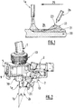
- the Figure 2 schematizes a hybrid MIG-TIG or MAG-TIG welding device, hereinafter referred to as a hybrid welding device, according to one embodiment of the invention.
- the hybrid welding device MIG-TIG or MAG-TIG comprises a welding torch 1 MIG or MAG comprising, at its end facing the parts to be welded, a metal fuse wire la.
- the fuse wire is oriented in a first direction 1b.
- the first direction 1b is perpendicular to the upper surface of said parts.
- the first direction 1b therefore forms an angle of the order of 0 ° with the vertical.
- the hybrid welding device also comprises a TIG welding torch 2 comprising, at its end facing the parts to be welded, a non-fuse electrode 2a.
- the end 2c of the electrode 2a is formed of a tip having a conical sharpening. More specifically, this sharpening generally takes the form of a cone of revolution whose opening angle is between 20 and 40 °, preferably of the order of 30 °.
- the electrode 2a is oriented in a second direction 2b, said first and second directions 1b and 2b being substantially coplanar and forming between them an angle ⁇ of between 5 and 40 °.
- the angle ⁇ is between 10 ° and 30 °, more preferably between 15 ° and 25 °, advantageously between 18 and 23 °, and ideally of the order of 20 °.
- the plane containing the first and second direction 1b and 2b is perpendicular to the surface of the parts to be welded.
- the hybrid welding device further comprises a shoe 5 for assembling the torches 1 and 2 in which they are arranged.
- the welding torch 1 MIG or MAG is arranged in the shoe 5, which shoe 5 is adapted to and designed to allow positioning of the TIG welding torch 2 in at least two predefined positions relative to the torch 1 MIG welding or MAG.
- These at least two predefined positions comprise a first position in which the end 2c of the non-fuse electrode 2a is at a first distance D of the first direction 1b, and a second position in which the end 2c of the electrode non-fuse 2a is located at a second distance D 'of the first direction 1b, the second distance D' being greater than the first distance D.
- Figure 2 illustrates an embodiment in which the TIG welding torch 2 can be arranged in two positions with respect to the MIG or MAG welding torch.
- the distances D and D ' are defined as the distances separating a first point corresponding to the position of the end 2c of the non-fuse electrode 2a and a second point resulting from the orthogonal projection of the first point on the axis defined by the direction 1b.
- the distance D is typically between 20 and 26 mm. These values are particularly advantageous when it is desired to weld stainless steel metal parts. Ideally, for the welding of stainless steel parts, the distance D is of the order of 24 mm.
- the distance D ' is typically between 36 and 44 mm. These values are particularly advantageous when it is desired to weld metal parts of mild steel, i. e. carbon steel. Ideally, for the welding of mild steel parts, the distance D 'is of the order of 40 mm.
- the device of the invention may comprise a shoe 5 allowing additional positions of the torch 2 TIG relative to the torch 1 MIG or MAG.
- the end 2c of the non-fuse electrode 2a can then be positioned at as many additional distances D ", D '" ... as additional positions permitted by the shoe 5.
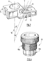
- FIG. Figure 3 The assembly shoe of the hybrid welding device of the invention is illustrated in FIG. Figure 3 without a MIG or MAG welding torch 1 and a TIG welding torch 2 being arranged therein.
- the assembly shoe 5 comprises an axial housing 6 passing through the shoe 5 over its entire thickness in the first direction 1b and opening opposite the metal parts to be welded.
- This axial housing 6 accommodates the welding torch 1 MIG or MAG.
- the axial housing 6 is a passage having a section of cylindrical shape formed in the thickness of the shoe 5.
- the axial housing 6 may include variations in the dimensions of its inside diameter along the first direction 1b, it is that is to say enlargements or narrowing of this diameter, or be of constant inner diameter along the first direction 1b.
- the axial housing 6 may comprise, along all or part of its inner wall, a portion comprising a first thread.
- the end of the torch 1 MIG or MAG provided with the fuse wire la and a nozzle 30 for dispensing the shielding gas protrudes below the shoe 5, that is to say that it is positioned between the shoe 5 and the surface of the metal parts to be welded next to the welding device.
- the assembled shoe 5 comprises means 9 for adjusting in translation the position of the MIG or MAG welding torch 1 along the first direction 1b.
- these translational adjustment means 9 comprise at least one screw that can move in translation in an oblong hole made in a shim placed on the side of the shoe 5. Said shim can slide parallel to the first direction 1b. In this way, the length of the shim protruding below the shoe 5 is adjusted.
- the means 9 allow a precise adjustment of the portion of the end of the torch 1 MIG or MAG protruding from the shoe 5. It is thus possible to adjust the distance between the nozzle 30 equipping the end of the torch 1 MIG or MAG and the metal parts to be welded, this distance constituting one of the parameters of the welding process operated by the device of the invention.
- the hybrid welding device of the invention further comprises a clamp 10 in which is arranged the welding torch 1 MIG or MAG.
- This clamp 10 is itself arranged in the axial housing 6 and serves as an adapter piece for arranging any type of MIG or MAG welding torch 1 in the axial housing 6 of the assembly shoe 5.
- the clamp 10 is schematized on the Figure 4 .
- the clamp 10 is a part of revolution comprising a portion 10a of cylindrical shape whose outer diameter corresponds to the inner diameter of the axial housing 6.
- a second thread is formed on the outer surface of the portion 10a of the clamp 10, the pitch of this second thread being adapted to the pitch of the first thread formed on all or part of the inner wall of the axial housing 6 so that the clamp 10 can be screwed into the axial housing 6.
- the clamp 10 also comprises a portion 10b adapted for and designed to grip and hold the MIG or MAG torch 1.
- the assembled shoe 5 comprises a first lateral housing 7 passing through said shoe 5 in which is arranged the TIG welding torch 2 when it is positioned in the first position.
- the assembly shoe 5 also comprises a second lateral housing 8 passing through the shoe 5 in which the TIG welding torch 2 is arranged when it is positioned in the second position.
- the lateral housings 7 and 8 are passages through the shoe 5 over its entire thickness and opening opposite metal parts to be welded.
- the lateral housings 7 and 8 are passages whose section is of cylindrical shape made in the thickness of the shoe 5.
- the central axes of these passages represented by the discontinuous lines (---) on the Figure, 3 form according to the invention an angle ⁇ with the axis of the axial housing 6 coinciding with the first direction 1b, represented by the continuous line (_).
- the lateral housings 7 and 8 may comprise variations in the dimensions of their inner diameters along their central axes, that is to say enlargements or narrowing of these diameters, or have constant inside diameters along their central axes.
- the lateral housing 7 or the lateral housing 8 may comprise a narrowing of its inner diameter forming a shoulder on which bears at least a portion of the TIG welding torch 2.
- the end of the torch 2 TIG provided with the non-fuse electrode 2a and a nozzle 40 for distribution of the shielding gas also protrudes below the shoe 5, that is to say that it is positioned between the shoe 5 and the surface of the metal parts to be welded next to the welding device.
- the shoe 5 comprises fastening means 11, 13 or 12, 13 of the TIG welding torch 2 in the first or second lateral housings 7, 8.
- the fixing means comprise lateral orifices 11 or 12 in which a screw or a threaded pin 13 can be arranged.
- the pin or the screw 13 is placed in the orifice 11 of the shoe 5 when the torch 2 TIG is positioned in the first position and in the hole 12 of the shoe 5 when the torch 2 TIG is positioned in the second position.
- the pin or the screw 13 passes through the thickness of the shoe 5 in which the orifices 11 and 12 are made and comes to hold the torch 2 TIG.
- the device of the invention comprises a set of spacers allowing the user to adapt any type of TIG torches or MIG or MAG torches in the housing 6, 7 or 8 of the shoe 5.
- the shoe 5 is advantageously formed of a block, in other words the shoe 5 is formed of a single block and not an assembly of parts.
- the housings 6, 7 and 8 are made by machining or drilling in this block.
- the shoe 5 is made of aluminum.
- the invention also relates to a hybrid MIG-TIG or MAG-TIG welding installation comprising a MIG or MAG welding torch 1 and a TIG welding torch 2 electrically connected to at least one current generator.
- the torches 1 and 2 are also fluidly connected to at least one source of gas for supplying the nozzles 30 and 40 with shielding gas.
- the hybrid welding installation MIG-TIG or MAG-TIG comprises a movable beam on which is arranged the hybrid welding device according to the invention.
- Said hybrid welding device may itself be movable or not on the beam.
- the installation also includes a numerical control adapted and adapted to control the displacement of the movable beam and / or the hybrid welding device on said beam.
- the end 2c of the non-fuse electrode 2a is positioned at the rear of the first direction 1b of the fuse wire 1a according to the welding direction and at a distance D or D 'from said first direction 1b chosen according to the nature of the constituent metal of the metal parts to be welded.
- the choice of the distance separating the end 2c of the non-fuse electrode 2a from the first direction 1b is a function of the physical characteristics of the solder bath generated, in particular viscosity and thermal conductivity, which vary according to the nature of the welded material.
- the main application of the present invention is a method of welding metal parts of ferrous alloys, aluminum or aluminum alloy, preferably stainless steel or carbon steel.
- the end 2c of the non-fuse electrode 2a is preferably at the distance D of the first direction 1b.
- the end 2c of the non-fuse electrode (2a) is preferably at a distance D 'from the first direction 1b.
- the electric arc MIG or MAG-TIG and the electric arc TIG are protected by protective gas flows respectively delivered by the nozzles 30 and 40.
- the electric arc MIG or MAG is protected by a gas stream containing mainly at least one inert compound selected from helium and argon, preferably at least 80% (% by volume), and optionally a minor compound having an oxidizing chemical character selected from CO 2 and O 2 .
- the MIG or MAG electric arc is preferably protected by a gas flow containing approximately 98% argon and 2% CO 2 (% by volume).
- a gas stream containing a larger proportion of oxidizing compound for example a gas stream containing about 92% argon and 8% CO 2 or containing 82% of gas, is preferably used. argon and 18% CO 2 (% by volume).
- the electric arc TIG is protected by a flow of gas containing essentially argon, preferably at least 99.9% (% by volume) or a mixture of helium and argon, for example a gas stream containing 80% argon and 20% helium or containing 30% argon and 70% helium, or a mixture containing at least 95% argon and hydrogen (% by volume).
- gas containing essentially argon preferably at least 99.9% (% by volume) or a mixture of helium and argon, for example a gas stream containing 80% argon and 20% helium or containing 30% argon and 70% helium, or a mixture containing at least 95% argon and hydrogen (% by volume).
- the combination of a TIG arc with a MIG or MAG arc is advantageously used to combat the phenomenon of " humping " occurring at high welding speeds.
- the proximity between the two arcs and their rapid succession on one and the same area of the joint make the same joint zone successively hit first by the MIG or MAG arc, then by the TIG arc while the metal of this zone of joint is still liquid, that is to say in fusion after passage of the arc MIG or MAG.
- the TIG arc exerts its action on the welding bath formed by the arc MIG or MAG while it is still liquid.
- the welding bath will then take advantage of the heat flow generated by the TIG arc to not solidify but also the pressure exerted by this arc on the molten metal bump formed at the rear end of this bath, which allows to obtain a weld bead without or almost without bump type defects.
- MIG-TIG hybrid welding tests were carried out on sheets with a thickness of 1.5 mm.
- the invention is particularly advantageous for improving the productivity of a method of welding metal parts having a thickness of less than 3 mm, preferably less than 2 mm, since these thicknesses lead to high welding speeds for which the defect of humping "is most likely to happen.
Description
L'invention porte sur un dispositif de soudage associant une torche MIG ou MAG et une torche TIG et permettant une mise en oeuvre plus simple et plus rapide d'un procédé de soudage hybride MIG-TIG ou MAG-TIG. L'invention concerne également un procédé de soudage hybride MIG-TIG ou MAG-TIG de pièces métalliques utilisant le dispositif de soudage de l'invention, en particulier un procédé de soudage à grande vitesse de pièces métalliques de faibles épaisseurs.The invention relates to a welding device combining a MIG or MAG torch and a TIG torch and allowing a simpler and faster implementation of a hybrid MIG-TIG or MAG-TIG welding process. The invention also relates to a hybrid MIG-TIG or MAG-TIG welding process for metal parts using the welding device of the invention, in particular a method of high-speed welding of metal parts of small thicknesses.
Les procédés de soudage MIG, pour « Métal Inert Gas », ou MAG, pour « Métal Active Gas » reposent sur l'utilisation d'un arc électrique établi entre l'extrémité d'un fil métallique fusible et les pièces métalliques à souder. La chaleur de l'arc électrique permet de fondre le métal constitutif des pièces à souder ainsi que le métal constitutif du fil fusible, i. e le métal d'apport, ce qui génère un bain de soudure, c'est-à-dire un bain de métal liquide, formé du métal des pièces à souder et du métal du fil fusible fondu et transféré dans l'arc électrique.MIG welding processes, for "Metal Inert Gas ", or MAG, for "Metal Active Gas " rely on the use of an electric arc established between the end of a fuse wire and the metal parts to be welded. The heat of the electric arc melts the constituent metal of the parts to be welded and the constituent metal of the fuse wire, i. and the filler metal, which generates a solder bath, ie a bath of liquid metal, formed of the metal of the parts to be welded and the metal of the melted fusible wire and transferred into the electric arc.
On obtient un cordon de soudure par re-solidification progressive du bain de soudure et déplacement relatif du fil fusible et des pièces métalliques. En outre, un flux de gaz inerte est distribué sur le bain de soudure par une buse positionnée au-dessus des pièces à souder de manière à protéger le métal fondu de l'air ambiant.A weld bead is obtained by gradual re-solidification of the solder bath and relative movement of the fuse wire and metal parts. In addition, an inert gas flow is distributed over the weld pool by a nozzle positioned above the parts to be welded so as to protect the molten metal from the ambient air.
Au cours de l'opération de soudage MIG ou MAG, un flux de gaz de protection est distribué sur le bain de soudure par une buse positionnée au-dessus des pièces à souder, de manière à protéger le métal fondu de l'air ambiant.During the MIG or MAG welding operation, a protective gas flow is distributed over the solder bath by a nozzle positioned above the parts to be welded, so as to protect the molten metal from the ambient air.
La différence entre les procédés de soudage MIG ou MAG réside dans la nature du gaz de protection utilisé, à savoir inerte dans le cas du procédé MIG et active, plus précisément oxydante, dans le cas du procédé MAG.The difference between the MIG or MAG welding processes lies in the nature of the protective gas used, namely inert in the case of the MIG process and active, more precisely oxidizing, in the case of the MAG process.
Le procédé de soudage MIG ou MAG est généralement opéré avec une torche de soudage MIG ou MAG supportant le fil métallique servant d'électrode fusible et la buse apte à distribuer le gaz de protection du bain de soudure. La torche MIG ou MAG est reliée électriquement à au moins un générateur de courant délivrant un courant lisse ou pulsé, d'une intensité de l'ordre de 100 à 500 A, laquelle torche est également reliée fluidiquement à au moins une source de gaz inerte. L'ensemble de ces éléments, à savoir torche de soudage, générateur de courant, source de gaz, ainsi que les cables d'alimentations électriques, les circuits d'alimentation en gaz et les éléments mécaniques tels que bâti-supports et/ou poutre mobile sur lesquels est agencée la torche sont compris dans un ensemble appelé installation de soudage MIG ou MAG.The MIG or MAG welding process is generally performed with a MIG or MAG welding torch supporting the metal wire serving as a fuse electrode and the nozzle capable of distributing the shielding gas of the solder bath. The MIG or MAG torch is electrically connected to at least one current generator delivering a smooth or pulsed current, of an intensity of the order of 100 to 500 A, which torch is also fluidly connected to at least one source of inert gas. . All of these elements, namely welding torch, generator of current, source of gas, as well as the cables of power supplies, the gas supply circuits and the mechanical elements such as support frames and / or mobile beam on which the torch is arranged are included in a set called MIG or MAG welding system.
Habituellement, le procédé de soudage MIG ou MAG est utilisé pour souder des pièces métalliques formées de différents matériaux métalliques, notamment des pièces en alliages ferreux, en aluminium ou an alliage d'aluminium, de préférence en acier inoxydable ou en acier au carbone.Usually, the MIG or MAG welding process is used to weld metal parts formed of different metallic materials, including ferrous alloy parts, aluminum or aluminum alloy, preferably stainless steel or carbon steel.
A noter que par pièces métalliques, on entend au moins deux pièces métalliques distinctes ou alors une seule pièce à souder avec elle-même, par exemple les deux bords longitudinaux d'une feuille métallique de manière à former un tube soudé.Note that metal parts means at least two separate metal parts or a single piece to be welded with itself, for example the two longitudinal edges of a metal sheet so as to form a welded tube.
Outre le temps de préparation des pièces avant soudage et le taux de cordons de soudure mis au rebut, la productivité d'un procédé de soudage MIG ou MAG est gouvernée en grande partie par la vitesse de soudage des pièces métalliques.In addition to the preparation time of the parts before welding and the rate of discarded weld seams, the productivity of a MIG or MAG welding process is governed largely by the welding speed of the metal parts.
Afin d'augmenter la productivité du procédé de soudage MIG ou MAG, une solution évidente est donc d'augmenter la vitesse de soudage, c'est-à-dire la vitesse de déplacement relatif du fil fusible et des pièces métalliques à souder.In order to increase the productivity of the MIG or MAG welding process, an obvious solution is therefore to increase the welding speed, that is to say the relative speed of movement of the fuse wire and the metal parts to be welded.
Toutefois, il s'avère dans certains cas que les vitesses de soudage MIG ou MAG ne peuvent pas être augmentées au-delà d'une valeur limite, à laquelle des défauts commencent à apparaître sur les cordons de soudure. En particulier, on observe l'apparition de ces défauts lors du soudage de pièces métalliques de faibles épaisseurs, typiquement moins de 2 mm, ou dit autrement de tôles minces, pour lesquelles les vitesses de soudage sont relativement élevées, généralement entre 1.5 et 2 m/min.However, it turns out in some cases that the MIG or MAG welding speeds can not be increased beyond a limit value, at which defects begin to appear on the weld beads. In particular, the occurrence of these defects is observed when welding metal parts of small thicknesses, typically less than 2 mm, or otherwise known as thin sheets, for which the welding speeds are relatively high, generally between 1.5 and 2 m / min.
Un défaut couramment observé se traduit par un changement de la morphologie du cordon de soudure obtenu par soudage MIG ou MAG et porte le nom de « humping ». Il se traduit par l'apparition d'oscillations périodiques, ou dit autrement de bosses, à la surface du cordon de soudure et conduit à deux types de morphologie de cordon : la morphologie à région creusée ou « gouging région morphology » (GRM) et la morphologie dite de cylindre perlé ou « beaded cylinder morphology » (BCM).A commonly observed defect results in a change in the morphology of the weld bead obtained by MIG or MAG welding and is called " humping ". It results in the appearance of periodic oscillations, or otherwise known as bumps, at the surface of the weld bead and leads to two types of cord morphology: the gouging region morphology (GRM) and the so-called "pearled cylinder morphology " (BCM).
Les mécanismes conduisant à l'apparition du « humping » sont complexes et font intervenir la mécanique des fluides, la thermique et la physique de l'arc électrique utilisé en soudage MIG ou MAG. Par exemple, l'apparition du défaut BCM est liée à un mauvais mouillage qui génère une instabilité de pincement analogue à celle présentée dans la théorie de Rayleigh. En fait, le défaut GRM apparaît parce que le bain de soudure est chassé vers l'arrière de l'arc de soudage de façon très importante en raison des contraintes qui s'exercent. Ces contraintes résultent de la quantité de mouvement des gouttes de métal du fil fusible transférées dans l'arc électrique et de la pression magnétique exercée par l'arc électrique.The mechanisms leading to the appearance of " humping " are complex and involve the fluid mechanics, the thermal and the physics of the electric arc used in MIG or MAG welding. For example, the appearance of the BCM defect is linked to a bad wetting which generates a pinch instability similar to that presented in the Rayleigh theory. In fact, the GRM defect appears because the solder bath is driven towards the rear of the welding arc in a very important way because of the constraints that are exerted. These constraints result from the amount of movement of the metal drops of the fusible wire transferred in the electric arc and the magnetic pressure exerted by the electric arc.
De manière générale, le défaut de « humping » apparaît aux grandes vitesses de soudage du fait de l'élongation du bain de soudure, le fin film de métal liquide situé sous l'arc électrique et à l'arrière de celui-ci devenant vulnérable à une solidification anticipée sous la forme d'une surépaisseur de métal de bosses. Ce phénomène répété périodiquement va donner naissance à une succession de creux et de bosses à la surface du cordon de soudure.In general, the " humping " defect appears at the high welding speeds because of the elongation of the weld pool, the thin film of liquid metal located under the electric arc and at the rear of the latter becoming vulnerable at an anticipated solidification in the form of a thickness of bumps metal. This phenomenon repeated periodically will give rise to a succession of hollows and bumps on the surface of the weld bead.
Le défaut de « humping » est bien connu et notamment décrit dans les documents suivants :
-
T.C. Nguyen et al, The humping phenomenon during high speed gas metal arc welding, Science and technology of welding and joining, 2005, vol. 10, n° 4, pp. 447-459 -
M.H. Cho and D.F. Farson, Understanding bead hump formation in gas metal arc welding using a numerical simulation, Metallurgical and materials transactions B, vol. 38B, pp. 305-319 -
T.C. Nguyen, D.C. Weckman and D.A. Johnson, The discontinuous weld bead defect in high-speed gas metal arc welds, Welding Journal, 2007, vol. 86, n° 11, pp. 360-372 -
H.W. Choi, D.F. Farson and M.H. Cho, Using a hybrid laser plus GMAW processfor controlling the bead humping defect, Welding Journal, 2006, vol. 85, n° 8, pp. 174-179
-
TC Nguyen et al, The Humping Phenomenon During High Speed Gas Metal Arc Welding, Science and Technology of Welding and Joining, 2005, vol. 10, No. 4, pp. 447-459 -
MH Cho and DF Farson, Understanding bead hump training in gas metal arc welding using a numerical simulation, Metallurgical and materials transactions B, vol. 38B, pp. 305-319 -
TC Nguyen, DC Weckman and DA Johnson, The Discontinuous Weld Bead Defects in Gas High-speed Arc Welds, Welding Journal, 2007, vol. 86, No. 11, pp. 360-372 -
HW Choi, DF Farson and MH Cho, Using a hybrid laser plus GMAW process for controlling the huming defect, Welding Journal, 2006, vol. 85, No. 8, pp. 174-179
Or, le défaut de « humping » n'est pas acceptable d'un point de vue industriel, non seulement du fait de l'aspect des cordons de soudure obtenus, mais également du fait de la dégradation des propriétés mécaniques des cordons que cela entraîne.However, the lack of " humping " is not acceptable from an industrial point of view, not only because of the appearance of the weld seams obtained, but also because of the degradation of the mechanical properties of the cords that entails .
Il est alors nécessaire de diminuer la vitesse de soudage pour obtenir des cordons de soudure, ce qui nuit à la productivité du procédé de soudage MIG ou MAG et pose donc un problème majeur.It is then necessary to reduce the welding speed to obtain weld seams, which affects the productivity of the MIG or MAG welding process and therefore poses a major problem.
Il existe plusieurs solutions pour résoudre ce problème et augmenter les vitesses de soudage MIG ou MAG, sans que les cordons de soudure ne présente un aspect bosselé, comme par exemple préchauffer les pièces métalliques avant soudage MIG ou MAG ou utiliser deux torches MIG ou MAG synchronisées.There are several solutions to solve this problem and increase the MIG or MAG welding speeds, without the weld seams having a bumpy appearance, such as preheating the metal parts before MIG or MAG welding or use two synchronized MIG or MAG torches .
Cependant, toutes ces solutions sont compliquées à mettre en oeuvre, complexifient excessivement l'installation de soudage MIG ou MAG ou conduisent à une augmentation conséquente de l'énergie électrique mise en oeuvre au cours de l'opération de soudage, ce qui nuit également à l'efficacité et à la productivité de l'installation de soudage MIG ou MAG.However, all these solutions are complicated to implement, excessively complexify the MIG or MAG welding system or lead to a consequent increase in the electrical energy used during the welding operation, which also adversely affects the efficiency and productivity of the MIG or MAG welding system.
Une solution alternative pour augmenter les vitesses de soudage MIG ou MAG, sans que les cordons de soudure ne présente un aspect bosselé, a été proposée précédemment par les inventeurs de la présente invention.An alternative solution for increasing the MIG or MAG welding speeds, without the weld beads having a bumpy appearance, has been proposed previously by the inventors of the present invention.
Elle consiste à utiliser un dispositif de soudage formé d'une torche de soudage TIG, pour « Tungsten Inert Gas », associée à la torche de soudage MIG ou MAG, c'est-à-dire un dispositif de soudage hybride MIG-TIG ou MAG-TIG. Un arc électrique TIG est établi entre une électrode non fusible en tungstène disposée dans la torche de soudage TIG et les pièces métalliques à souder. La torche TIG est également munie d'une buse délivrant un flux de gaz inerte pour protéger le bain de fusion. L'arc électrique TIG est positionné en poursuite de l'arc électrique MIG ou MAG, c'est-à-dire qu'il est positionné à l'arrière de l'arc électrique MIG ou MAG en suivant la direction de soudage et qu'il se déplace simultanément à celui-ci.It consists in using a welding device formed of a TIG welding torch, for "Tungsten Inert Gas ", associated with the MIG or MAG welding torch, that is to say a hybrid MIG-TIG welding device or MAG-TIG. A TIG arc is established between a non-fusible tungsten electrode disposed in the TIG welding torch and the metal parts to be welded. The TIG torch is also provided with a nozzle delivering a flow of inert gas to protect the melt. The electric arc TIG is positioned in continuation of the electric arc MIG or MAG, that is to say that it is positioned at the rear of the electric arc MIG or MAG in the direction of welding and that it moves simultaneously to this one.
L'effet produit par l'arc TIG au cours du procédé de soudage est illustré sur la
D'une part, cet arc TIG vient fournir un flux de chaleur localisé (en 24) permettant de retarder la solidification anticipée du fin film de métal liquide qui apparaît en poursuite de l'arc électrique MIG ou MAG. D'autre part, l'arc TIG exerce une pression sur la bosse de métal fondu (en 23) qui apparaît à l'extrémité arrière du bain de soudure et conduit à l'apparition du défaut de « humping ». On the one hand, this TIG arc provides a localized heat flux (at 24) for delaying the anticipated solidification of the thin film of liquid metal that appears in continuation of the MIG or MAG electric arc. On the other hand, the TIG arc exerts pressure on the molten metal bump (at 23) which appears at the rear end of the weld pool and leads to the appearance of the "humping" defect .
Plus précisément, le fil fusible la de la torche MIG ou MAG est orienté selon une première direction donnée et l'électrode non fusible 2a de la torche de soudage TIG est orientée selon une deuxième direction donnée. Lesdites première et seconde directions sont sensiblement coplanaires et forment un angle typiquement supérieur à 5° et inférieur à 40°. L'extrémité de l'électrode de la torche de soudage TIG est située à une distance de ladite première direction comprise entre 20 et 44 mm.More specifically, the fuse wire la of the MIG or MAG torch is oriented in a first given direction and the
Ce dispositif de soudage hybride MIG-TIG ou MAG-TIG présente l'avantage de ne pas nécessiter de chauffer une grande partie des pièces à souder. On traite ponctuellement une zone du cordon de soudure peu après sa formation avec un arc TIG, donc la dépense d'énergie supplémentaire liée à l'utilisation de la torche TIG reste modérée.This hybrid welding device MIG-TIG or MAG-TIG has the advantage of not requiring to heat a large part of the parts to be welded. A zone of the weld bead is treated punctually shortly after its formation with a TIG arc, so the additional energy expenditure related to the use of the TIG torch remains moderate.
En effet, la torche TIG doit être liée mécaniquement à la torche MIG de manière à pouvoir la suivre dans ses mouvements et à fonctionner simultanément avec elle. En outre, le dispositif de soudage hybride MIG-TIG ou MAG-TIG doit comporter des moyens de réglage, tel un ou des vérins, engrenages..., permettant d'ajuster précisément la position relative desdites torches de soudage l'une par rapport à l'autre, c'est-à-dire la distance entre lesdites torches ou entre celles-ci et les pièces à souder, ou encore les différents angles d'inclinaison des torches.Indeed, the TIG torch must be mechanically linked to the MIG torch so that it can follow in its movements and operate simultaneously with it. In addition, the hybrid welding device MIG-TIG or MAG-TIG must comprise adjustment means, such as one or more jacks, gears ..., allowing precise adjustment of the relative position of said welding torches relative to one another. to the other, that is to say the distance between said torches or between them and the parts to be welded, or the different angles of inclination of the torches.
En particulier, selon la nature du matériau des pièces métalliques à souder, il est nécessaire d'adapter la distance séparant l'extrémité de l'électrode de la torche de soudage TIG et la première direction d'orientation du fil fusible de la torche MIG ou MAG.In particular, depending on the nature of the material of the metal parts to be welded, it is necessary to adapt the distance separating the end of the electrode from the TIG welding torch and the first orientation direction of the fuse wire of the MIG torch. or MAG.
Par exemple, lorsque les pièces métalliques à souder sont en acier inoxydable, l'extrémité de l'électrode non fusible doit se situer à une distance D donnée de ladite première direction d'orientation du fil fusible. Lorsque les pièces métalliques à souder sont en acier au carbone, l'extrémité de l'électrode non fusible doit se situer à une distance D' donnée de ladite première direction d'orientation du fil fusible, la distance D' étant supérieure à la distance D.For example, when the metal parts to be welded are made of stainless steel, the end of the non-fuse electrode must be at a given distance D from said first orientation direction of the fuse wire. When the metal parts to be welded are carbon steel, the end of the non-fuse electrode must be at a given distance D 'of said first orientation direction of the fuse wire, the distance D' being greater than the distance D.
Mais cela impose de réajuster la position relative des torches de soudage TIG et MIG ou MAG l'une par rapport à l'autre à chaque fois que l'on change de matériau pour les pièces métalliques à souder. Il s'ensuit un allongement du temps de préparation du dispositif avant l'opération de soudage et donc une perte de productivité de l'installation de soudage.But this requires readjusting the relative position of the TIG and MIG or MAG welding torches relative to each other every time we change material for the metal parts to be welded. This results in an increase in the preparation time of the device before the welding operation and therefore a loss of productivity of the welding installation.
Pour remédier à ce problème, une solution est de disposer d'autant de dispositifs de soudage hybride MIG-TIG ou MAG-TIG, en d'autres termes de configurations d'assemblage de torche MIG ou MAG et de torche TIG, que de types de matériau métallique à souder.To remedy this problem, one solution is to have as many hybrid MIG-TIG or MAG-TIG welding devices, in other words MIG or MAG torch assembly configurations and TIG torches, as types of metal material to be welded.
Toutefois, cette solution n'est pas idéale car elle augmente le coût global de l'installation de soudage et ne résout pas non plus le problème d'allongement du temps de préparation du dispositif avant l'opération de soudage. En effet, il est alors nécessaire de monter et de démonter le dispositif de soudage hybride MIG-TIG ou MAG-TIG du bâti-support ou de la poutre mobile sur lesquels il est généralement agencé.However, this solution is not ideal because it increases the overall cost of the welding installation and does not solve the problem of lengthening the preparation time of the device before the welding operation. Indeed, it is then necessary to mount and dismantle the hybrid welding device MIG-TIG or MAG-TIG of the support frame or the mobile beam on which it is generally arranged.
Au vu de cela, le problème à résoudre est dès lors de proposer un dispositif de soudage MIG amélioré, c'est-à-dire permettant d'accroitre la vitesse de soudage sans que les cordons de soudure obtenus ne présentent de défaut du type « humping », qui ne complexifie pas de manière excessive l'installation de soudage, ne nécessite pas un apport supplémentaire d'énergie trop important, et qui soit en outre de mise en oeuvre aisée et rapide.In view of this, the problem to be solved is therefore to propose an improved MIG welding device, that is to say, to increase the welding speed without the weld seams obtained having a defect of the type " humping ", which does not overly complexify the welding installation, does not require an additional supply of too much energy, and which is also easy and quick to implement.
Dit autrement, le problème à résoudre est de proposer un dispositif de soudage MIG ou MAG amélioré ne nécessitant pas, ou du moins un nombre grandement limité, de réglages mécaniques avant sa mise en oeuvre, et qui soit apte et conçu pour opérer le soudage de pièces métalliques quelque soit la nature du matériau constitutif desdites pièces.In other words, the problem to be solved is to propose an improved MIG or MAG welding device that does not require, or at least a greatly limited number, mechanical adjustments before its implementation, and that is suitable and designed to operate the welding of metal parts regardless of the nature of the constituent material of said parts.
La solution de l'invention est alors un dispositif de soudage hybride MIG-TIG ou MAG-TIG comprenant une torche de soudage MIG ou MAG comprenant un fil fusible orienté selon une première direction, associée à une torche de soudage TIG comprenant une électrode non fusible orientée selon une deuxième direction, lesdites première et deuxième directions étant sensiblement coplanaires et formant entre elles un angle compris entre 5 et 40°,
caractérisé en ce qu'il comprend en outre un sabot d'assemblage des torches apte à et conçu pour permettre un positionnement de la torche de soudage TIG selon au moins deux positions prédéfinies par rapport à la torche de soudage MIG ou MAG comprenant :
- une première position dans laquelle l'extrémité de l'électrode non fusible se situe à une première distance de la première direction, et
- au moins une deuxième position dans laquelle l'extrémité de l'électrode non fusible se situe à une deuxième distance de la première direction, la deuxième distance étant supérieure à la première distance.
- un logement axial traversant le sabot selon la première direction, dans lequel est agencée la torche de soudage MIG ou MAG, un premier logement latéral traversant le sabot dans lequel est agencée la torche de soudage TIG lorsqu'elle est positionnée dans la première position, et au moins un deuxième logement latéral traversant le sabot dans lequel est agencée la torche de soudage TIG lorsqu'elle est positionnée dans la deuxième position.
characterized in that it further comprises a torch assembly shoe adapted to and adapted to allow positioning of the TIG welding torch in at least two predefined positions with respect to the MIG or MAG welding torch comprising:
- a first position in which the end of the non-fuse electrode is at a first distance from the first direction, and
- at least a second position in which the end of the non-fuse electrode is at a second distance from the first direction, the second distance being greater than the first distance.
- an axial housing passing through the shoe in the first direction, in which the welding torch MIG or MAG is arranged, a first lateral housing passing through the shoe in which the TIG welding torch is arranged when it is positioned in the first position, and at least one second lateral housing passing through the shoe in which the TIG welding torch is arranged when it is positioned in the second position.
Par ailleurs, selon le mode de réalisation considéré, l'invention peut comprendre l'une ou plusieurs des caractéristiques suivantes:
- la première distance est comprise
entre 20 et 26 mm. - la deuxième distance est comprise entre 36 et 44 mm.
- lesdites première et seconde directions forment entre elles un angle compris entre 10° et 30°.
- lesdites première et seconde directions forment un angle compris entre 15° et 25°, de préférence entre 18 et 23°, avantageusement de l'ordre de 20°.
- le sabot comprend en outre des moyens de fixation pour maintenir la torche de soudage TIG dans les premier ou deuxième logements latéraux.
- le sabot comprend en outre des moyens d'ajustement en translation de la position de la torche de soudage MIG ou MAG le long de la première direction.
- le dispositif de soudage hybride comprend en outre une pince agencée dans le logement axial et dans laquelle est insérée la torche de soudage MIG ou MAG.
- le sabot est formé d'un bloc.
- le sabot est en aluminium.
- the first distance is between 20 and 26 mm.
- the second distance is between 36 and 44 mm.
- said first and second directions form between them an angle of between 10 ° and 30 °.
- said first and second directions form an angle of between 15 ° and 25 °, preferably between 18 and 23 °, advantageously of the order of 20 °.
- the shoe further comprises fastening means for holding the TIG welding torch in the first or second lateral housing.
- the shoe further comprises means for adjusting in translation the position of the MIG or MAG welding torch along the first direction.
- the hybrid welding device further comprises a clamp arranged in the axial housing and in which is inserted the welding torch MIG or MAG.
- the hoof is formed of a block.
- the hoof is made of aluminum.
Selon un autre aspect, l'invention concerne également une installation de soudage hybride MIG-TIG ou MAG-TIG comprenant une torche de soudage MIG ou MAG et une torche de soudage TIG reliées électriquement à au moins un générateur de courant et reliées fluidiquement à au moins une source de gaz, caractérisée en ce qu'elle comprend en outre une poutre mobile sur laquelle est agencé un dispositif de soudage hybride MIG-TIG selon l'invention, ledit dispositif de soudage hybride MIG-TIG ou MAG-TIG étant mobile ou non, et une commande numérique apte à et conçue pour contrôler le déplacement de la poutre mobile et/ou du dispositif de soudage hybride MIG-TIG ou MAG-TIG.According to another aspect, the invention also relates to a hybrid MIG-TIG or MAG-TIG welding installation comprising a MIG or MAG welding torch and a TIG welding torch electrically connected to at least one current generator and fluidly connected to less a gas source, characterized in that it further comprises a movable beam on which is arranged a hybrid MIG-TIG welding device according to the invention, said hybrid welding device MIG-TIG or MAG-TIG being mobile or no, and a numerical control adapted to and designed to control the displacement of the mobile beam and / or the hybrid MIG-TIG or MAG-TIG welding device.
En outre, l'invention porte aussi sur un procédé de soudage hybride MIG-TIG ou MAG-TIG de pièces métalliques (30) mettant en oeuvre un dispositif de soudage hybride MIG-TIG ou MAG-TIG selon l'invention et dans lequel, pendant le soudage :
- on établit un arc électrique MIG ou MAG entre le fil fusible (1a) de la torche (1) de soudage MIG ou MAG et les pièces métalliques à souder de manière à générer un bain de soudure, ledit arc électrique MIG ou MAG étant protégé par un flux de gaz contenant majoritairement au moins un composé inerte choisi parmi l'hélium et l'argon, et
- on établit un arc électrique TIG entre l'électrode non fusible (2a) de la torche (2) de soudage TIG et les pièces métalliques à souder sur au moins une partie dudit bain de soudure, ledit arc électrique TIG étant protégé par un flux de gaz contenant essentiellement de l'argon ou un mélange d'hélium et d'argon.
- an MIG or MAG electric arc is established between the fuse wire (1a) of the MIG or MAG welding torch (1) and the metal parts to be welded so as to generate a solder bath, said MIG or MAG electric arc being protected by a gas stream containing predominantly at least one inert compound selected from helium and argon, and
- an electric arc TIG is established between the non-fuse electrode (2a) of the TIG welding torch (2) and the metal parts to be welded on at least a part of said solder bath, said TIG electric arc being protected by a flux of gas containing essentially argon or a mixture of helium and argon.
De préférence, le procédé selon l'invention comprend l'une ou plusieurs des caractéristiques suivantes :
- l'arc électrique MIG ou MAG est protégé par un flux de gaz contenant au moins 80% d'au moins un composé inerte choisi parmi l'hélium et l'argon (% en volume).
- le flux de gaz protégeant l'arc électrique MIG ou MAG contient en outre un composé minoritaire à caractère chimique oxydant choisi parmi CO2 et O2.
- lorsque les pièces soudées sont en acier inoxydable, le flux de gaz protégeant l'arc électrique MIG ou MAG contient environ 98% d'argon et 2% de CO2 (% en volume).
- lorsque les pièces soudées sont formées d'acier au carbone, le flux de gaz protégeant l'arc électrique MIG ou MAG contient environ 92% d'argon et 8% de CO2 ou 82% d'argon et 18% de CO2 (% en volume).
- le flux de gaz protégeant l'arc électrique TIG contient essentiellement de l'argon, de préférence au moins 99.9% d'argon (% en volume).
- le flux de gaz protégeant l'arc électrique TIG contient au moins 95% d'argon et de l'hydrogène (% en volume).
- le flux de gaz protégeant l'arc électrique TIG contient un mélange d'hélium et d'argon.
- le flux de gaz protégeant l'arc électrique TIG contient un mélange de 80% d'argon et 20% d'hélium (% en volume).
- le flux de gaz protégeant l'arc électrique TIG contient un mélange de 30% d'argon et 70% d'hélium (% en volume).
- the MIG or MAG electric arc is protected by a flow of gas containing at least 80% of at least one inert compound selected from helium and argon (% by volume).
- the flow of gas protecting the electric arc MIG or MAG further contains a minority compound with an oxidizing chemical character selected from CO 2 and O 2 .
- when the welded parts are made of stainless steel, the flow of gas protecting the MIG or MAG electric arc contains about 98% argon and 2% CO 2 (% by volume).
- when the welded parts are made of carbon steel, the flow of gas protecting the MIG or MAG electric arc contains about 92% argon and 8% CO 2 or 82% argon and 18% CO 2 ( % in volume).
- the flow of gas protecting the electric arc TIG essentially contains argon, preferably at least 99.9% argon (% by volume).
- the gas flow protecting the TIG arc contains at least 95% argon and hydrogen (% by volume).
- the gas flow protecting the TIG electric arc contains a mixture of helium and argon.
- the gas flow protecting the electric arc TIG contains a mixture of 80% argon and 20% helium (% by volume).
- the gas flow protecting the TIG arc contains a mixture of 30% argon and 70% helium (% by volume).
L'invention va maintenant être mieux comprise grâce à la description détaillée suivante faite en références aux Figures annexées parmi lesquelles :
- la
Figure 2 schématise un dispositif de soudage hybride MIG-TIG ou MAG-TIG selon un mode de réalisation de l'invention, - la
Figure 3 schématise un sabot d'assemblage des torches MIG ou MAG et TIG selon un mode de réalisation de l'invention, et - la
Figure 4 illustre une pince pour torche MIG utilisée dans un mode de réalisation de l'invention.
- the
Figure 2 schematizes a hybrid MIG-TIG or MAG-TIG welding device according to one embodiment of the invention, - the
Figure 3 schematizes an assembly shoe MIG torches or MAG and TIG according to one embodiment of the invention, and - the
Figure 4 illustrates a MIG torch clamp used in one embodiment of the invention.
La
Comme on le voit sur la
De préférence, lorsque des pièces métalliques à souder sont positionnées en regard de la torche 1 de soudage MIG ou MAG, la première direction 1b est perpendiculaire à la surface supérieure desdites pièces. Dans le cas de soudage de pièces maintenues à plat, i. e. horizontalement, la première direction 1b forme donc un angle de l'ordre de 0° avec la verticale.Preferably, when metal parts to be welded are positioned opposite the welding torch 1 MIG or MAG, the
Le dispositif de soudage hybride comprend également une torche 2 de soudage TIG comprenant, en son extrémité située en regard des pièces à souder, une électrode non fusible 2a. L'extrémité 2c de l'électrode 2a est formée d'une pointe présentant un affûtage conique. Plus précisément, cet affûtage prend en général la forme d'un cône de révolution dont l'angle d'ouverture est compris entre 20 et 40°, de préférence de l'ordre de 30°.The hybrid welding device also comprises a
L'électrode 2a est orientée selon une deuxième direction 2b, lesdites première et deuxième directions 1b et 2b étant sensiblement coplanaires et formant entre elles un angle α compris entre 5 et 40°. De préférence l'angle α est compris entre 10° et 30°, de préférence encore compris entre 15° et 25°, avantageusement entre 18 et 23°, et idéalement de l'ordre de 20°.The
Préférentiellement, le plan contenant les première et deuxième direction 1b et 2b est perpendiculaire à la surface des pièces à souder.Preferably, the plane containing the first and
Selon l'invention, le dispositif de soudage hybride comprend en outre un sabot 5 d'assemblage des torches 1 et 2 dans lequel celles-ci sont agencées. La torche 1 de soudage MIG ou MAG est agencée dans le sabot 5, lequel sabot 5 est apte à et conçu pour permettre un positionnement de la torche 2 de soudage TIG selon au moins deux positions prédéfinies par rapport à la torche 1 de soudage MIG ou MAG.According to the invention, the hybrid welding device further comprises a
Ces au moins deux positions prédéfinies comprennent une première position dans laquelle l'extrémité 2c de l'électrode non fusible 2a se situe à une première distance D de la première direction 1b, et une deuxième position dans laquelle l'extrémité 2c de l'électrode non fusible 2a se situe à une deuxième distance D' de la première direction 1b, la deuxième distance D' étant supérieure à la première distance D. La
Comme illustré sur la
Dans le cadre de l'invention, la distance D est typiquement comprise entre 20 et 26 mm. Ces valeurs sont particulièrement avantageuses lorsque l'on souhaite souder des pièces métalliques en acier inoxydable. Idéalement, pour le soudage de pièces en acier inoxydable, la distance D est de l'ordre de 24 mm.In the context of the invention, the distance D is typically between 20 and 26 mm. These values are particularly advantageous when it is desired to weld stainless steel metal parts. Ideally, for the welding of stainless steel parts, the distance D is of the order of 24 mm.
La distance D' est typiquement comprise entre 36 et 44 mm. Ces valeurs sont particulièrement avantageuses lorsque l'on souhaite souder des pièces métalliques en acier doux, i. e. en acier au carbone. Idéalement, pour le soudage de pièces en acier doux, la distance D' est de l'ordre de 40 mm.The distance D 'is typically between 36 and 44 mm. These values are particularly advantageous when it is desired to weld metal parts of mild steel, i. e. carbon steel. Ideally, for the welding of mild steel parts, the distance D 'is of the order of 40 mm.
Optionnellement, le dispositif de l'invention peut comprendre un sabot 5 autorisant des positions supplémentaires de la torche 2 TIG par rapport à la torche 1 MIG ou MAG. L'extrémité 2c de l'électrode non fusible 2a peut alors être positionnée à autant de distances supplémentaires D", D'"... que de positions supplémentaires permises par le sabot 5.Optionally, the device of the invention may comprise a
Le sabot 5 d'assemblage du dispositif de soudage hybride de l'invention est illustré sur la
Conformément à l'invention, le sabot 5 d'assemblage comprend un logement axial 6 traversant le sabot 5 sur toute son épaisseur selon la première direction 1b et débouchant en regard des pièces métalliques à souder. Ce logement axial 6 accueille la torche 1 de soudage MIG ou MAG. De préférence, le logement axial 6 est un passage ayant une section de forme cylindrique pratiqué dans l'épaisseur du sabot 5. Le logement axial 6 peut comprendre des variations des dimensions de son diamètre intérieur le long de la première direction 1b, c'est-à-dire des élargissements ou des rétrécissements de ce diamètre, ou bien être de diamètre intérieur constant le long de la première direction 1b. De manière optionnelle, le logement axial 6 peut comprendre, le long de tout ou partie de sa paroi intérieure, une portion comprenant un premier filetage. L'extrémité de la torche 1 MIG ou MAG munie du fil fusible la et d'une buse 30 de distribution du gaz de protection vient dépasser sous le sabot 5, c'est-à-dire qu'elle est positionnée entre le sabot 5 et la surface des pièces métalliques à souder située en regard du dispositif de soudage.According to the invention, the
En outre, comme montré sur la
Les moyens 9 permettent un ajustement précis de la partie de l'extrémité de la torche 1 MIG ou MAG qui dépasse du sabot 5. Il est ainsi possible de régler la distance entre la buse 30 équipant l'extrémité de la torche 1 MIG ou MAG et les pièces métalliques à souder, cette distance constituant un des paramètres du procédé de soudage opéré par le dispositif de l'invention.The means 9 allow a precise adjustment of the portion of the end of the torch 1 MIG or MAG protruding from the
Selon un mode particulier de réalisation de l'invention, comme illustré en
Un mode de réalisation de la pince 10 est schématisé sur la
En outre, comme représenté sur la
Le sabot s'assemblage 5 comprend également un deuxième logement latéral 8 traversant le sabot 5 dans lequel est agencée la torche 2 de soudage TIG lorsqu'elle est positionnée dans la deuxième position.The
Plus précisément, les logement latéraux 7 et 8 sont des passages traversant le sabot 5 sur toute son épaisseur et débouchant en regard des pièces métalliques à souder. De préférence, les logements latéraux 7 et 8 sont des passages dont la section est de forme cylindrique pratiqués dans l'épaisseur du sabot 5. Les axes centraux de ces passages, représentés par les lignes discontinues (---) sur la
Les logements latéraux 7 et 8 peuvent comprendre des variations des dimensions de leurs diamètres intérieurs le long de leurs axes centraux, c'est-à-dire des élargissements ou des rétrécissements de ces diamètres, ou bien avoir des diamètres intérieurs constants le long de leurs axes centraux. De manière optionnelle, le logement latéral 7 ou le logement latéral 8 peut comprendre un rétrécissement de son diamètre intérieur formant un épaulement sur lequel vient s'appuyer au moins une partie de la torche 2 de soudage TIG.The
L'extrémité de la torche 2 TIG munie de l'électrode non fusible 2a et d'une buse 40 de distribution du gaz de protection vient elle aussi dépasser sous le sabot 5, c'est-à-dire qu'elle est positionnée entre le sabot 5 et la surface des pièces métalliques à souder située en regard du dispositif de soudage.The end of the
Le sabot 5 comprend des moyens de fixation 11, 13 ou 12, 13 de la torche 2 de soudage TIG dans les premier ou deuxième logements latéraux 7, 8. Selon un mode de réalisation, illustré sur les
De manière optionnelle, le dispositif de l'invention comprend un jeu d'entretoises permettant à l'utilisateur d'adapter tout type de torches TIG ou de torches MIG ou MAG dans les logements 6, 7 ou 8 du sabot 5.Optionally, the device of the invention comprises a set of spacers allowing the user to adapt any type of TIG torches or MIG or MAG torches in the
Pour une meilleure robustesse mécanique du dispositif de l'invention, le sabot 5 est avantageusement formé d'un bloc, en d'autres termes le sabot 5 est formé d'un seul bloc et non d'un assemblage de pièces. Les logements 6, 7 et 8 sont pratiqué par usinage ou perçage dans ce bloc. De préférence, le sabot 5 est en aluminium.For better mechanical strength of the device of the invention, the
Selon un autre aspect, l'invention concerne également une installation de soudage hybride MIG-TIG ou MAG-TIG comprenant une torche 1 de soudage MIG ou MAG et une torche 2 de soudage TIG reliées électriquement à au moins un générateur de courant. Les torches 1 et 2 sont également reliées fluidiquement à au moins une source de gaz servant à alimenter les buses 30 et 40 en gaz de protection.According to another aspect, the invention also relates to a hybrid MIG-TIG or MAG-TIG welding installation comprising a MIG or MAG welding torch 1 and a
En outre, l'installation de soudage hybride MIG-TIG ou MAG-TIG comprend une poutre mobile sur laquelle est agencé le dispositif de soudage hybride selon l'invention. Ledit dispositif de soudage hybride peut être lui-même mobile ou non sur la poutre. L'installation comporte également une commande numérique apte à et conçue pour contrôler le déplacement de la poutre mobile et/ou du dispositif de soudage hybride sur ladite poutre.In addition, the hybrid welding installation MIG-TIG or MAG-TIG comprises a movable beam on which is arranged the hybrid welding device according to the invention. Said hybrid welding device may itself be movable or not on the beam. The installation also includes a numerical control adapted and adapted to control the displacement of the movable beam and / or the hybrid welding device on said beam.
Par ailleurs, l'invention concerne également un procédé de soudage hybride MIG-TIG ou MAG-TIG de pièces métalliques mettant en oeuvre le dispositif et l'installation de l'invention. Le soudage de pièces métallique est opéré par déplacement relatif d'un dispositif de soudage hybride MIG-TIG ou MAG-TIG selon l'invention par rapport aux pièces métalliques à souder selon une direction dite de soudage et comprend les étapes de :
- a) générer un bain de soudure par fusion du métal constitutif des pièces métalliques à souder au moyen d'un arc électrique MIG ou MAG établi entre le fil fusible la de la torche 1 de soudage MIG ou MAG-TIG et les pièces métalliques à souder,
- b) amener un arc électrique TIG établi entre l'électrode non fusible 2a de la torche 2 de soudage TIG et les pièces métalliques à souder sur au moins une partie du bain de soudure généré à l'étape a), et
- c) obtenir des pièces métalliques soudées par re-solidification du métal constitutif de celles-ci.
- a) generating a welding bath by melting the constituent metal of the metal parts to be welded by means of a MIG or MAG electric arc established between the
fuse wire 1a of the MIG or MAG-TIG welding torch 1 and the metal parts to be welded , - b) bringing an electric arc TIG established between the
non-fuse electrode 2a of theTIG welding torch 2 and the metal parts to be welded on at least a part of the solder bath generated in step a), and - c) obtain metal parts welded by re-solidification of the constituent metal thereof.
Conformément à l'invention, l'extrémité 2c de l'électrode non fusible 2a est positionnée à l'arrière de la première direction 1b du fil fusible la selon la direction de soudage et à une distance D ou D' de ladite première direction 1b choisie selon la nature du métal constitutif des pièces métalliques à souder. Le choix de la distance séparant l'extrémité 2c de l'électrode non fusible 2a de la première direction 1b est fonction des caractéristiques physiques du bain de soudure généré, notamment viscosité et conductivité thermique, qui varient selon la nature du matériau soudé.According to the invention, the end 2c of the
L'application principale de la présente invention est un procédé de soudage de pièces métalliques en alliages ferreux, en aluminium ou an alliage d'aluminium, de préférence en acier inoxydable ou en acier au carbone.The main application of the present invention is a method of welding metal parts of ferrous alloys, aluminum or aluminum alloy, preferably stainless steel or carbon steel.
Lorsque les pièces métalliques à souder sont en acier inoxydable, l'extrémité 2c de l'électrode non fusible 2a se situe de préférence à la distance D de la première direction 1b. Lorsque les pièces métalliques à souder sont en acier au carbone, l'extrémité 2c de l'électrode non fusible (2a) se situe de préférence à une distance D' de la première direction 1b.When the metal parts to be welded are made of stainless steel, the end 2c of the
Au cours de l'opération de soudage, l'arc électrique MIG ou MAG-TIG et l'arc électrique TIG sont protégés par des flux de gaz de protection délivrés respectivement par les buses 30 et 40.During the welding operation, the electric arc MIG or MAG-TIG and the electric arc TIG are protected by protective gas flows respectively delivered by the
Avantageusement, l'arc électrique MIG ou MAG est protégé par un flux de gaz contenant majoritairement au moins un composé inerte choisi parmi l'hélium et l'argon, de préférence au moins 80% (% en volume), et optionnellement un composé minoritaire à caractère chimique oxydant choisi parmi CO2 et O2.Advantageously, the electric arc MIG or MAG is protected by a gas stream containing mainly at least one inert compound selected from helium and argon, preferably at least 80% (% by volume), and optionally a minor compound having an oxidizing chemical character selected from CO 2 and O 2 .
Par exemple, pour le soudage des aciers inoxydables, on protège de préférence l'arc électrique MIG ou MAG par un flux de gaz contenant environ 98% d'argon et 2% de CO2 (% en volume). Pour le soudage des aciers au carbone, on utilise de préférence un flux de gaz contenant un proportion plus importante de composé oxydant, par exemple un flux de gaz contenant environ 92% d'argon et 8% de CO2 ou contenant 82% d'argon et 18% de CO2 (% en volume).For example, for welding stainless steels, the MIG or MAG electric arc is preferably protected by a gas flow containing approximately 98% argon and 2% CO 2 (% by volume). For the welding of carbon steels, a gas stream containing a larger proportion of oxidizing compound, for example a gas stream containing about 92% argon and 8% CO 2 or containing 82% of gas, is preferably used. argon and 18% CO 2 (% by volume).
L'arc électrique TIG est protégé par un flux de gaz contenant essentiellement de l'argon, de préférence au moins 99.9% (% en volume) ou un mélange d'hélium et d'argon, par exemple un flux de gaz contenant 80% d'argon et 20% d'hélium ou contenant 30% d'argon et 70% d'hélium, ou encore un mélange contenant au moins 95 % d'argon et de l'hydrogène (% en volume).The electric arc TIG is protected by a flow of gas containing essentially argon, preferably at least 99.9% (% by volume) or a mixture of helium and argon, for example a gas stream containing 80% argon and 20% helium or containing 30% argon and 70% helium, or a mixture containing at least 95% argon and hydrogen (% by volume).
Comme mentionné précédemment, on utilise avantageusement la combinaison d'un arc TIG avec un arc MIG ou MAG pour lutter contre le phénomène de « humping » apparaissant aux grandes vitesses de soudage. En fait, la proximité entre les deux arcs et leur succession rapide sur une même zone du joint font que cette même zone de joint est frappée successivement par d'abord l'arc MIG ou MAG, puis ensuite par l'arc TIG alors que le métal de cette zone de joint est encore liquide, c'est-à-dire en fusion après passage de l'arc MIG ou MAG.As mentioned above, the combination of a TIG arc with a MIG or MAG arc is advantageously used to combat the phenomenon of " humping " occurring at high welding speeds. In fact, the proximity between the two arcs and their rapid succession on one and the same area of the joint make the same joint zone successively hit first by the MIG or MAG arc, then by the TIG arc while the metal of this zone of joint is still liquid, that is to say in fusion after passage of the arc MIG or MAG.
Il s'ensuit que l'arc TIG vient exercer son action sur le bain de soudage formé par l'arc MIGou MAG alors qu'il est encore liquide. Le bain de soudage va alors profiter du flux de chaleur généré par l'arc TIG pour ne pas se solidifier mais aussi de la pression exercée par cet arc sur la bosse de métal fondu formée à l'extrémité arrière de ce bain, ce qui permet d'obtenir un cordon de soudure sans ou quasi sans défauts de type bosselage.It follows that the TIG arc exerts its action on the welding bath formed by the arc MIG or MAG while it is still liquid. The welding bath will then take advantage of the heat flow generated by the TIG arc to not solidify but also the pressure exerted by this arc on the molten metal bump formed at the rear end of this bath, which allows to obtain a weld bead without or almost without bump type defects.
Afin de démontrer l'efficacité du dispositif de soudage hybride MIG-TIG ou MAG-TIG de l'invention pour souder sans défaut et à grande vitesse des pièces métalliques, en particulier des pièces de faible épaisseur, des essais de soudage hybride MIG-TIG ont été menés sur des tôles d'une épaisseur de 1.5 mm.In order to demonstrate the effectiveness of the hybrid MIG-TIG or MAG-TIG welding device of the invention for defectless and high-speed welding of metal parts, in particular thin-gauge parts, MIG-TIG hybrid welding tests. were carried out on sheets with a thickness of 1.5 mm.
Un premier essai de soudage a été réalisé sur des pièces en acier inoxydable à plat. Les paramètres de soudage étaient les suivants :
- le gaz de protection MIG contenaient 98% d'argon et 2% de CO2 (% en volume), correspondant au mélange ARCAL 12 commercialisé par AIR LIQUIDE,
- le gaz de protection TIG contenait de l'argon, correspondant au mélange ARCAL 1 (degré de pureté de l'argon de l'ordre de 99.998% en volume) commercialisé par AIR LIQUIDE,
- la distance D séparant l'extrémité 2c de l'électrode 2a TIG de la première
direction 1b était de 24 mm, - l'angle α formé entre la première
direction 1b du fil fusible la de la torche MIG et la deuxièmedirection 2b de l'électrode non fusible 2a de la torche TIG était de 20°, - la
première direction 1b était perpendiculaire à la surface des pièces à souder, i. e. formait un angle de 0° avec la verticale, - l'angle d'affûtage de l'électrode TIG était de 30°,
- la torche TIG était alimentée par un courant lisse d'une intensité de 250A,
- la distance entre l'extrémité de l'électrode 2c et les pièces à souder était de 3mm,
- la torche MIG était alimentée par un courant lisse d'une intensité 272 A, la tension d'arc étant de 27 V et la distance entre la buse de la torche MIG et la pièce étant de 13 mm,
- la vitesse de dévidage du fil fusible de la torche MIG était de 13.2 m/min.
- the MIG shielding gas contained 98% of argon and 2% of CO 2 (% by volume), corresponding to the
ARCAL 12 mixture sold by AIR LIQUIDE, - the TIG shielding gas contained argon, corresponding to the ARCAL 1 mixture (degree of purity of argon of the order of 99.998% by volume) marketed by AIR LIQUID,
- the distance D between the end 2c of the
electrode 2a TIG of thefirst direction 1b was 24 mm, - the angle α formed between the
first direction 1b of thefuse wire 1a of the MIG torch and thesecond direction 2b of thenon-fuse electrode 2a of the TIG torch was 20 °, - the
first direction 1b was perpendicular to the surface of the parts to be welded, ie formed an angle of 0 ° with the vertical, - the sharpening angle of the TIG electrode was 30 °,
- the TIG torch was powered by a smooth current of 250A,
- the distance between the end of the electrode 2c and the parts to be welded was 3 mm,
- the MIG torch was fed with a smooth current of an intensity 272 A, the arc voltage being 27 V and the distance between the nozzle of the MIG torch and the workpiece being 13 mm,
- the winding speed of the fuse wire of the MIG torch was 13.2 m / min.
Lors de ces essais, une vitesse de soudage élevée, de l'ordre de 3.2 m/min, a pu être utilisée, sans que les cordons obtenus ne présentent de défaut de « humping ». Les cordons obtenus possédaient de bonnes caractéristiques métallurgiques.During these tests, a high welding speed, of the order of 3.2 m / min, could be used, without the cords obtained having a "humping" defect . The cords obtained had good metallurgical characteristics.
Un deuxième essai de soudage a été réalisé sur des pièces sur acier carbone à plat d'une épaisseur de 1.5 mm. Les paramètres de soudage étaient les suivants :
- le gaz de protection MIG contenaient 92% d'argon et 8% de CO2 (% en volume), correspondant au mélange ARCAL 21 commercialisé par AIR LIQUIDE,
- le gaz de protection TIG contenait de l'argon, correspondant au mélange ARCAL 1 (degré de pureté de l'argon de l'ordre de 99.998% en volume) commercialisé par AIR LIQUIDE,
- la distance D séparant l'extrémité 2c de l'électrode 2a TIG de la première
direction 1b était de 40 mm, - l'angle α formé entre la première
direction 1b du fil fusible la de la torche MIG et la deuxièmedirection 2b de l'électrode non fusible 2a de la torche TIG était de 20°, - la
première direction 1b était perpendiculaire à la surface des pièces à souder, i. e. formait un angle de 0° avec la verticale, - l'angle d'affûtage de l'électrode TIG était de 30°,
- la torche TIG était alimentée par un courant lisse d'une intensité de 350A,
- la distance entre l'extrémité de l'électrode 2c et les pièces à souder était de 3mm,
- la torche MIG était alimentée par un courant pulsé d'une intensité 314 A, la tension d'arc étant de 32.4 V et la distance entre la buse de la torche MIG et la pièce étant de 13 mm,
- la vitesse de dévidage du fil fusible de la torche MIG était de 18.5 m/min.
- the MIG shielding gas contained 92% of argon and 8% of CO 2 (% by volume), corresponding to the
ARCAL 21 mixture sold by AIR LIQUIDE, - the TIG shielding gas contained argon, corresponding to the ARCAL 1 mixture (degree of purity of argon of the order of 99.998% by volume) marketed by AIR LIQUID,
- the distance D between the end 2c of the
electrode 2a TIG of thefirst direction 1b was 40 mm, - the angle α formed between the
first direction 1b of thefuse wire 1a of the MIG torch and thesecond direction 2b of thenon-fuse electrode 2a of the TIG torch was 20 °, - the
first direction 1b was perpendicular to the surface of the parts to be welded, ie formed an angle of 0 ° with the vertical, - the sharpening angle of the TIG electrode was 30 °,
- the TIG torch was powered by a smooth current of an intensity of 350A,
- the distance between the end of the electrode 2c and the parts to be welded was 3 mm,
- the MIG torch was powered by a pulsed current of an intensity 314 A, the arc voltage being 32.4 V and the distance between the nozzle of the MIG torch and the workpiece being 13 mm,
- the feed speed of the fuse wire of the MIG torch was 18.5 m / min.
Lors de ces essais, une vitesse de soudage élevée, de l'ordre de 2.8 m/min, a pu être utilisée. Les cordons obtenus ne présentaient pas de défaut de « humping » et possédaient de bonnes caractéristiques métallurgiques.During these tests, a high welding speed, of the order of 2.8 m / min, could be used. The cords obtained showed no "humping" defect and had good metallurgical characteristics.
Les résultats de ces essais confirment l'intérêt du dispositif de soudage hybride MIG-TIG de l'invention qui permet d'améliorer les performances de soudage MIG et de souder des pièces métallique à grande vitesse sans que les cordons ne présente de défaut du type bosselage. En outre, il est possible, avec un seul dispositif de souder différents types de matériaux pour lesquels les distances entre l'extrémité de l'électrode TIG et la direction du fil MIG doivent être différentes. Le dispositif réduit le nombre d'ajustements nécessaires avant d'opérer le soudage des pièces avec les dispositifs de soudage hybride de l'art antérieur puisque les torches sont assemblées mécaniquement par un sabot autorisant des positions relatives prédéterminées des deux torches TIG et MIG ou MAG. Il est ainsi possible, avec un même dispositif, de souder différents types de matériaux. En outre, le dispositif ne complexifie pas de manière excessive l'installation de soudage, ne nécessite pas un apport supplémentaire d'énergie trop important.The results of these tests confirm the interest of the hybrid MIG-TIG welding device of the invention which makes it possible to improve the MIG welding performance and to weld metal parts at high speed without the cords having any type of defect. bumpiness. In addition, it is possible, with a single device to weld different types of materials for which the distances between the end of the TIG electrode and the direction of the MIG wire must be different. The device reduces the number of necessary adjustments before welding the parts with the hybrid welding devices of the prior art since the torches are mechanically assembled by a shoe allowing predetermined relative positions of the two torches TIG and MIG or MAG . It is thus possible, with the same device, to weld different types of materials. In addition, the device does not overcomplicate the welding installation, does not require an additional supply of too much energy.
L'invention est particulièrement avantageuse pour améliorer la productivité d'un procédé de soudage de pièces métalliques ayant une épaisseur inférieure à 3 mm, de préférence inférieure à 2 mm, puisque ces épaisseurs conduisent à des vitesses de soudage importantes pour lesquelles le défaut de « humping » est le plus susceptible de se produire.The invention is particularly advantageous for improving the productivity of a method of welding metal parts having a thickness of less than 3 mm, preferably less than 2 mm, since these thicknesses lead to high welding speeds for which the defect of humping "is most likely to happen.
Claims (18)
- A hybrid MIG-TIG or MAG-TIG welding device comprising a MIG or MAG welding torch (1) comprising a consumable wire (1a) oriented in a first direction (1b), associated with a TIG welding torch (2) that comprises a non-consumable electrode (2a) oriented in a second direction (2b), said first and second directions (1b, 2b) being substantially coplanar and forming between them an angle (α) of between 5 and 40 °,
characterized in that it further comprises a torch (1,2) assembly shoe (5) adapted to and designed to allow positioning of the TIG welding torch (2) in at least two predefined positions with respect to the MIG or MAG welding torch (1) comprising:- a first position in which the end (2c) of the non-consumable electrode (2a) is at a first distance (D) from the first direction (1b),- at least a second position in which the end (2c) of the non-consumable electrode (2a) is at a second distance (D') from the first direction (1b), the second distance (D') being greater than the first distance (D),- an axial housing (6) passing through the shoe (5) in the first direction (1b), in which the MIG or MAG welding torch (1) is arranged,- a first lateral housing (7) passing through the shoe (5) in which the TIG welding torch (2) is arranged when it is positioned in the first position, and- at least a second lateral housing (8) passing through the shoe (5) in which the TIG welding torch (2) is arranged when it is positioned in the second position. - Device according to one of the preceding claims, characterized in that the first distance (D) is between 20 and 26 mm.
- Device according to one of the preceding claims, characterized in that the second distance (D') is between 36 and 44 mm.
- Device according to one of the preceding claims, characterized in that said first and second directions (1b, 2b) form between them an angle (α) between 10° and 30°.
- Device according to one of the preceding claims, characterized in that the shoe (5) further comprises fixing means (11, 13) or (12, 13) for holding the TIG welding torch (2) in the first or second lateral housing (7, 8).
- Device according to one of the preceding claims, characterized in that the shoe (5) further comprises means (9) for adjusting in translation the position of the MIG or MAG welding torch (1) along the first direction (1b).
- Device according to one of the preceding claims, characterized in that it further comprises a clamp (10) arranged in the axial housing (6) and wherein is inserted in the MIG or MAG welding torch (1).
- Device according to one of the preceding claims, characterized in that the shoe (5) is formed of a block.
- A hybrid MIG-TIG or MAG-TIG welding system comprising a MIG or MAG welding torch (1) and a TIG welding torch (2) electrically connected to at least one current generator and fluidly connected to at least one source of gas, characterized in that it further comprises a movable beam on which is arranged a hybrid MIG-TIG welding device according to one of the preceding claims, said hybrid welding device MIG-TIG or MAG-TIG being movable or not, and a numerical control adapted to and designed to control the displacement of the mobile beam and/or the hybrid MIG-TIG or MAG-TIG welding device.
- A method of hybrid MIG-TIG or MAG-TIG welding of metal parts (30) characterized in that it implements a hybrid MIG-TIG or MAG-TIG welding device according to one of claims 1 to 8 and in which, during the welding:- a MIG or MAG electric arc is established between the consumable wire (1a) of the MIG or MAG welding torch (1) and the metal parts to be welded so as to generate a solder bath, said MIG or MAG electric arc being protected by a stream of gas containing mainly at least one inert compound selected from helium and argon, and- a TIG electric arc is established between the non-consumable electrode (2a) of the TIG welding torch (2) and the metal parts to be welded on at least a part of said solder bath, said TIG electric arc being protected by a stream of gas containing mainly argon or a mixture of helium and argon.
- The method of claim 10, characterized in that the MIG or MAG electric arc is protected by a gas stream containing at least 80% of at least one inert compound selected from helium and argon (% by volume).
- Method according to one of claims 10 or 11, characterized in that the gas stream protecting the electric arc MIG or MAG further contains a minority compound with an oxidizing chemical chosen from CO2 and O2.
- Method according to one of claims 10 to 12, characterized in that when the welded parts are stainless steel, the gas stream protecting the MIG or MAG electric arc contains about 98% argon and 2% CO2 (% by volume).
- Method according to one of claims 10 to 12, characterized in that when the welded parts are formed of carbon steel, the stream of gas protecting the electric arc MIG or MAG contains about 92% argon and 8% CO2 or 82% argon and 18% CO2 (% by volume).
- The method of claim 10, characterized in that the gas stream protecting the electric arc TIG essentially contains argon, preferably at least 99.9% argon (% by volume).
- Method according to one of claims 10 or 15, characterized in that the gas stream protecting the TIG electric arc contains at least 95% argon and hydrogen (% by volume).
- Method according to one of claims 10 or 15, characterized in that the gas stream protecting the TIG electric arc contains a mixture of helium and argon.
- Method according to one of claims 10, 15 or 17, characterized in that the gas stream protecting the TIG electric arc contains:- a mixture of 80% argon and 20% helium (% by volume),- or a mixture of 30% argon and 70% helium (% by volume).
Applications Claiming Priority (2)
| Application Number | Priority Date | Filing Date | Title |
|---|---|---|---|
| FR1250270A FR2985446B1 (en) | 2012-01-11 | 2012-01-11 | MIG-TIG OR MAG-TIG HYBRID WELDING DEVICE |
| PCT/FR2012/052808 WO2013104839A1 (en) | 2012-01-11 | 2012-12-05 | Hybrid mig-tig or mag-tig welding device |
Publications (2)
| Publication Number | Publication Date |
|---|---|
| EP2802435A1 EP2802435A1 (en) | 2014-11-19 |
| EP2802435B1 true EP2802435B1 (en) | 2019-09-04 |
Family
ID=47505212
Family Applications (1)
| Application Number | Title | Priority Date | Filing Date |
|---|---|---|---|
| EP12810347.0A Not-in-force EP2802435B1 (en) | 2012-01-11 | 2012-12-05 | Mig/tig or mag/tig hybrid welding device |
Country Status (4)
| Country | Link |
|---|---|
| US (1) | US20150014284A1 (en) |
| EP (1) | EP2802435B1 (en) |
| FR (1) | FR2985446B1 (en) |
| WO (1) | WO2013104839A1 (en) |
Families Citing this family (7)
| Publication number | Priority date | Publication date | Assignee | Title |
|---|---|---|---|---|
| DE102014002213B4 (en) * | 2014-02-21 | 2016-01-14 | MHIW b.v. | Method and burner head for metal inert gas welding |
| US20160339533A1 (en) * | 2015-05-18 | 2016-11-24 | Abb Technology Ag | Robotically controlled gas tungsten arc welder and method for operating the same |
| US10807179B2 (en) | 2017-02-17 | 2020-10-20 | General Electric Company | Method of build-up welding |
| CN107790886B (en) * | 2017-09-15 | 2019-09-17 | 哈尔滨工业大学(威海) | Pulsed negative pressure formula laser enhancing KTIG and MIG composite welding apparatus and method |
| CN108788395A (en) * | 2018-06-22 | 2018-11-13 | 山东大学 | A kind of integral type TIG by the double wire feeds of sidewall symmetry welds nozzle and welding gun |
| CN110434498A (en) * | 2019-07-24 | 2019-11-12 | 昆山华恒焊接股份有限公司 | Paraxonic formula hybrid welding torch |
| US11738403B2 (en) | 2020-01-27 | 2023-08-29 | The Esab Group Inc. | Push pull torch |
Citations (1)
| Publication number | Priority date | Publication date | Assignee | Title |
|---|---|---|---|---|
| DE2426017A1 (en) * | 1974-05-30 | 1976-03-25 | Materialdata Ab | Adjustable burner arrgmt - for cutting and preparing the edge of plates for welding |
Family Cites Families (13)
| Publication number | Priority date | Publication date | Assignee | Title |
|---|---|---|---|---|
| US2623576A (en) * | 1948-01-28 | 1952-12-30 | Shell Dev | Cutting torch with inclined and offset cutting oxygen discharge passage |
| US2591926A (en) * | 1948-07-03 | 1952-04-08 | Air Reduction | Inert gas shielded arc welding method |
| DE1941393U (en) * | 1964-02-18 | 1966-06-30 | Linde Ag | ARC WELDING DEVICE. |
| GB1188024A (en) * | 1967-04-05 | 1970-04-15 | Welding Inst | Improvements in or relating to Arc Welding Processes and Apparatus. |
| DE4106900A1 (en) * | 1991-03-05 | 1992-09-10 | Messer Griesheim Gmbh | PROTECTIVE GAS FOR TIG, MIG, MAG AND PLASMA WELDING |
| FR2769863B1 (en) * | 1997-10-16 | 1999-12-17 | Soudure Autogene Francaise | MIG WELDING METHOD AND DEVICE WITH CURRENT MODULATION |
| FR2809647B1 (en) * | 2000-05-31 | 2002-08-30 | Air Liquide | HYBRID LASER-ARC WELDING PROCESS WITH APPROPRIATE GAS MIXTURE |
| FR2813544B1 (en) * | 2000-09-06 | 2002-10-18 | Air Liquide | PROCESS FOR MIG WELDING OF NICKEL AND NICKEL ALLOYS WITH ARGON AND CO2-BASED PROTECTION GAS |
| US6693252B2 (en) * | 2002-04-01 | 2004-02-17 | Illinois Tool Works Inc. | Plasma MIG welding with plasma torch and MIG torch |
| US20070007264A1 (en) * | 2005-07-11 | 2007-01-11 | Lincoln Global, Inc. | Hex mount for welding torch |
| EP1920872A4 (en) * | 2005-08-31 | 2009-06-10 | Taiyo Nippon Sanso Corp | Shielding gas for hybrid welding and welding method using such gas |
| DE102007033291A1 (en) * | 2007-07-17 | 2009-01-22 | Linde Ag | Method of arc joining |
| JP5466484B2 (en) * | 2009-11-06 | 2014-04-09 | 株式会社神戸製鋼所 | Arc welding system, single arc welding system and tandem arc welding system |
-
2012
- 2012-01-11 FR FR1250270A patent/FR2985446B1/en not_active Expired - Fee Related
- 2012-12-05 EP EP12810347.0A patent/EP2802435B1/en not_active Not-in-force
- 2012-12-05 WO PCT/FR2012/052808 patent/WO2013104839A1/en active Application Filing
- 2012-12-05 US US14/327,122 patent/US20150014284A1/en not_active Abandoned
Patent Citations (1)
| Publication number | Priority date | Publication date | Assignee | Title |
|---|---|---|---|---|
| DE2426017A1 (en) * | 1974-05-30 | 1976-03-25 | Materialdata Ab | Adjustable burner arrgmt - for cutting and preparing the edge of plates for welding |
Also Published As
| Publication number | Publication date |
|---|---|
| WO2013104839A1 (en) | 2013-07-18 |
| FR2985446B1 (en) | 2014-02-14 |
| FR2985446A1 (en) | 2013-07-12 |
| US20150014284A1 (en) | 2015-01-15 |
| EP2802435A1 (en) | 2014-11-19 |
Similar Documents
| Publication | Publication Date | Title |
|---|---|---|
| EP2802435B1 (en) | Mig/tig or mag/tig hybrid welding device | |
| EP2605880B1 (en) | Arc welding device and process using an mig/mag torch combined with a tig torch | |
| EP1736270B2 (en) | TIG welding/brazing method with liquid bridge metal transfer | |
| EP1923165A1 (en) | Laser welding process improving penetration | |
| EP1632306A1 (en) | High wire speed laser-MIG hybrid welding process | |
| EP1427564A1 (en) | Hybrid laser-arc welding method with gas flow rate adjustment | |
| FR2904576A1 (en) | SOUDO-TIG SOLDER WITH METAL TRANSFER BY DROPS AND WITH CONTROLLED FREQUENCY | |
| EP1459831A2 (en) | Nozzle/ wire guide assembly for a robotic TIG welding torch | |
| FR2829415A1 (en) | Method, for hybrid arc-laser welding of metal components, involves combining the use of a laser beam and an electric arc in the presence of a controlled protective gas atmosphere | |
| EP2313228B1 (en) | Slag-free mig/mag flux-cored wire containing lithium with co2-based gas, and method for mig/mag electric-arc welding using such flux-cored wire | |
| FR3012759A3 (en) | SYSTEM AND METHOD FOR WELDING AND / OR RECHARGING WITH ADDITIONAL WIRE | |
| FR2818569A1 (en) | METHOD AND DEVICE FOR ARC WELDING PULSE | |
| FR3010339A1 (en) | LASER BEAM WELDING METHOD ON SANDWICH WITH CONTROL OF CAPILLARY OPENING | |
| EP1655096B1 (en) | Installation for arc welding with several torches using a non-consumable electrode and double protective flux for welding tubes, each torch having the electrode tip located in the plane of the inner nozzle | |
| CA2644189C (en) | Nozzle/wire guide assembly for robotic tig welding torch | |
| EP3065908B1 (en) | Method of electric arc surfacing with gas protection consisting of an argon/helium gas mixture | |
| FR2986451A1 (en) | Metal inert gas or metal active gas welding of two metal parts, comprises gradually melting metal constitutive of metal parts to weld along line of assembly by electric arc established between end of fusible wire and metal parts | |
| BE1018063A6 (en) | WELDING AUTOMATE AND WELDING METHOD | |
| EP2590772B1 (en) | Mig/mag welding with rotative arc for carbon steel and ar/he/o2 gas mixture | |
| FR2974526A1 (en) | Device, useful for welding an electric arc, comprises a contact tube that is passed through a welding wire and is adapted for supplying the wire with electric current, and a guiding piece, where the welding wire has a protruding portion | |
| FR2781171A1 (en) | ELECTRIC ARC WELDING NOSE OF CONTROLLED DIAMETER AND THICKNESS | |
| FR2941160A1 (en) | Torch for arc welding of a first edge of a metal piece with a second edge of the metal piece, comprises a body with an elongated tungsten electrode having a free end, a device for supply of fused welding wire, and guiding devices |
Legal Events
| Date | Code | Title | Description |
|---|---|---|---|
| PUAI | Public reference made under article 153(3) epc to a published international application that has entered the european phase |
Free format text: ORIGINAL CODE: 0009012 |
|
| 17P | Request for examination filed |
Effective date: 20140811 |
|
| AK | Designated contracting states |
Kind code of ref document: A1 Designated state(s): AL AT BE BG CH CY CZ DE DK EE ES FI FR GB GR HR HU IE IS IT LI LT LU LV MC MK MT NL NO PL PT RO RS SE SI SK SM TR |
|
| DAX | Request for extension of the european patent (deleted) | ||
| RIN1 | Information on inventor provided before grant (corrected) |
Inventor name: PLANCKAERT, JEAN-PIERRE Inventor name: BURVELLE, NICOLAS |
|
| STAA | Information on the status of an ep patent application or granted ep patent |
Free format text: STATUS: EXAMINATION IS IN PROGRESS |
|
| 17Q | First examination report despatched |
Effective date: 20180511 |
|
| REG | Reference to a national code |
Ref country code: DE Ref legal event code: R079 Ref document number: 602012063699 Country of ref document: DE Free format text: PREVIOUS MAIN CLASS: B23K0009280000 Ipc: B23K0009230000 |
|
| GRAP | Despatch of communication of intention to grant a patent |
Free format text: ORIGINAL CODE: EPIDOSNIGR1 |
|
| STAA | Information on the status of an ep patent application or granted ep patent |
Free format text: STATUS: GRANT OF PATENT IS INTENDED |
|
| RIC1 | Information provided on ipc code assigned before grant |
Ipc: B23K 35/38 20060101ALI20190304BHEP Ipc: B23K 9/28 20060101ALI20190304BHEP Ipc: B23K 9/173 20060101ALI20190304BHEP Ipc: B23K 9/167 20060101ALI20190304BHEP Ipc: B23K 9/23 20060101AFI20190304BHEP |
|
| INTG | Intention to grant announced |
Effective date: 20190321 |
|
| GRAS | Grant fee paid |
Free format text: ORIGINAL CODE: EPIDOSNIGR3 |
|
| RAP1 | Party data changed (applicant data changed or rights of an application transferred) |
Owner name: LINCOLN ELECTRIC FRANCE SAS |
|
| GRAA | (expected) grant |
Free format text: ORIGINAL CODE: 0009210 |
|
| STAA | Information on the status of an ep patent application or granted ep patent |
Free format text: STATUS: THE PATENT HAS BEEN GRANTED |
|
| AK | Designated contracting states |
Kind code of ref document: B1 Designated state(s): AL AT BE BG CH CY CZ DE DK EE ES FI FR GB GR HR HU IE IS IT LI LT LU LV MC MK MT NL NO PL PT RO RS SE SI SK SM TR |
|
| REG | Reference to a national code |
Ref country code: GB Ref legal event code: FG4D Free format text: NOT ENGLISH |
|
| REG | Reference to a national code |
Ref country code: CH Ref legal event code: EP |
|
| REG | Reference to a national code |
Ref country code: AT Ref legal event code: REF Ref document number: 1174675 Country of ref document: AT Kind code of ref document: T Effective date: 20190915 |
|
| REG | Reference to a national code |
Ref country code: DE Ref legal event code: R096 Ref document number: 602012063699 Country of ref document: DE Ref country code: IE Ref legal event code: FG4D Free format text: LANGUAGE OF EP DOCUMENT: FRENCH |
|
| REG | Reference to a national code |
Ref country code: NL Ref legal event code: MP Effective date: 20190904 |
|
| REG | Reference to a national code |
Ref country code: LT Ref legal event code: MG4D |
|
| PG25 | Lapsed in a contracting state [announced via postgrant information from national office to epo] |
Ref country code: HR Free format text: LAPSE BECAUSE OF FAILURE TO SUBMIT A TRANSLATION OF THE DESCRIPTION OR TO PAY THE FEE WITHIN THE PRESCRIBED TIME-LIMIT Effective date: 20190904 Ref country code: LT Free format text: LAPSE BECAUSE OF FAILURE TO SUBMIT A TRANSLATION OF THE DESCRIPTION OR TO PAY THE FEE WITHIN THE PRESCRIBED TIME-LIMIT Effective date: 20190904 Ref country code: BG Free format text: LAPSE BECAUSE OF FAILURE TO SUBMIT A TRANSLATION OF THE DESCRIPTION OR TO PAY THE FEE WITHIN THE PRESCRIBED TIME-LIMIT Effective date: 20191204 Ref country code: SE Free format text: LAPSE BECAUSE OF FAILURE TO SUBMIT A TRANSLATION OF THE DESCRIPTION OR TO PAY THE FEE WITHIN THE PRESCRIBED TIME-LIMIT Effective date: 20190904 Ref country code: FI Free format text: LAPSE BECAUSE OF FAILURE TO SUBMIT A TRANSLATION OF THE DESCRIPTION OR TO PAY THE FEE WITHIN THE PRESCRIBED TIME-LIMIT Effective date: 20190904 Ref country code: NO Free format text: LAPSE BECAUSE OF FAILURE TO SUBMIT A TRANSLATION OF THE DESCRIPTION OR TO PAY THE FEE WITHIN THE PRESCRIBED TIME-LIMIT Effective date: 20191204 |
|
| PG25 | Lapsed in a contracting state [announced via postgrant information from national office to epo] |
Ref country code: RS Free format text: LAPSE BECAUSE OF FAILURE TO SUBMIT A TRANSLATION OF THE DESCRIPTION OR TO PAY THE FEE WITHIN THE PRESCRIBED TIME-LIMIT Effective date: 20190904 Ref country code: LV Free format text: LAPSE BECAUSE OF FAILURE TO SUBMIT A TRANSLATION OF THE DESCRIPTION OR TO PAY THE FEE WITHIN THE PRESCRIBED TIME-LIMIT Effective date: 20190904 Ref country code: GR Free format text: LAPSE BECAUSE OF FAILURE TO SUBMIT A TRANSLATION OF THE DESCRIPTION OR TO PAY THE FEE WITHIN THE PRESCRIBED TIME-LIMIT Effective date: 20191205 Ref country code: AL Free format text: LAPSE BECAUSE OF FAILURE TO SUBMIT A TRANSLATION OF THE DESCRIPTION OR TO PAY THE FEE WITHIN THE PRESCRIBED TIME-LIMIT Effective date: 20190904 |
|
| REG | Reference to a national code |
Ref country code: AT Ref legal event code: MK05 Ref document number: 1174675 Country of ref document: AT Kind code of ref document: T Effective date: 20190904 |
|
| PG25 | Lapsed in a contracting state [announced via postgrant information from national office to epo] |
Ref country code: RO Free format text: LAPSE BECAUSE OF FAILURE TO SUBMIT A TRANSLATION OF THE DESCRIPTION OR TO PAY THE FEE WITHIN THE PRESCRIBED TIME-LIMIT Effective date: 20190904 Ref country code: IT Free format text: LAPSE BECAUSE OF FAILURE TO SUBMIT A TRANSLATION OF THE DESCRIPTION OR TO PAY THE FEE WITHIN THE PRESCRIBED TIME-LIMIT Effective date: 20190904 Ref country code: PT Free format text: LAPSE BECAUSE OF FAILURE TO SUBMIT A TRANSLATION OF THE DESCRIPTION OR TO PAY THE FEE WITHIN THE PRESCRIBED TIME-LIMIT Effective date: 20200106 Ref country code: EE Free format text: LAPSE BECAUSE OF FAILURE TO SUBMIT A TRANSLATION OF THE DESCRIPTION OR TO PAY THE FEE WITHIN THE PRESCRIBED TIME-LIMIT Effective date: 20190904 Ref country code: AT Free format text: LAPSE BECAUSE OF FAILURE TO SUBMIT A TRANSLATION OF THE DESCRIPTION OR TO PAY THE FEE WITHIN THE PRESCRIBED TIME-LIMIT Effective date: 20190904 Ref country code: NL Free format text: LAPSE BECAUSE OF FAILURE TO SUBMIT A TRANSLATION OF THE DESCRIPTION OR TO PAY THE FEE WITHIN THE PRESCRIBED TIME-LIMIT Effective date: 20190904 Ref country code: PL Free format text: LAPSE BECAUSE OF FAILURE TO SUBMIT A TRANSLATION OF THE DESCRIPTION OR TO PAY THE FEE WITHIN THE PRESCRIBED TIME-LIMIT Effective date: 20190904 |
|
| PG25 | Lapsed in a contracting state [announced via postgrant information from national office to epo] |
Ref country code: SK Free format text: LAPSE BECAUSE OF FAILURE TO SUBMIT A TRANSLATION OF THE DESCRIPTION OR TO PAY THE FEE WITHIN THE PRESCRIBED TIME-LIMIT Effective date: 20190904 Ref country code: IS Free format text: LAPSE BECAUSE OF FAILURE TO SUBMIT A TRANSLATION OF THE DESCRIPTION OR TO PAY THE FEE WITHIN THE PRESCRIBED TIME-LIMIT Effective date: 20200224 Ref country code: SM Free format text: LAPSE BECAUSE OF FAILURE TO SUBMIT A TRANSLATION OF THE DESCRIPTION OR TO PAY THE FEE WITHIN THE PRESCRIBED TIME-LIMIT Effective date: 20190904 Ref country code: CZ Free format text: LAPSE BECAUSE OF FAILURE TO SUBMIT A TRANSLATION OF THE DESCRIPTION OR TO PAY THE FEE WITHIN THE PRESCRIBED TIME-LIMIT Effective date: 20190904 |
|
| REG | Reference to a national code |
Ref country code: DE Ref legal event code: R097 Ref document number: 602012063699 Country of ref document: DE |
|
| REG | Reference to a national code |
Ref country code: DE Ref legal event code: R119 Ref document number: 602012063699 Country of ref document: DE |
|
| PLBE | No opposition filed within time limit |
Free format text: ORIGINAL CODE: 0009261 |
|
| STAA | Information on the status of an ep patent application or granted ep patent |
Free format text: STATUS: NO OPPOSITION FILED WITHIN TIME LIMIT |
|
| PG2D | Information on lapse in contracting state deleted |
Ref country code: IS |
|
| PG25 | Lapsed in a contracting state [announced via postgrant information from national office to epo] |
Ref country code: DK Free format text: LAPSE BECAUSE OF FAILURE TO SUBMIT A TRANSLATION OF THE DESCRIPTION OR TO PAY THE FEE WITHIN THE PRESCRIBED TIME-LIMIT Effective date: 20190904 Ref country code: IS Free format text: LAPSE BECAUSE OF FAILURE TO SUBMIT A TRANSLATION OF THE DESCRIPTION OR TO PAY THE FEE WITHIN THE PRESCRIBED TIME-LIMIT Effective date: 20200105 |
|
| REG | Reference to a national code |
Ref country code: CH Ref legal event code: PL |
|
| 26N | No opposition filed |
Effective date: 20200605 |
|
| REG | Reference to a national code |
Ref country code: BE Ref legal event code: MM Effective date: 20191231 |
|
| PG25 | Lapsed in a contracting state [announced via postgrant information from national office to epo] |
Ref country code: MC Free format text: LAPSE BECAUSE OF FAILURE TO SUBMIT A TRANSLATION OF THE DESCRIPTION OR TO PAY THE FEE WITHIN THE PRESCRIBED TIME-LIMIT Effective date: 20190904 Ref country code: SI Free format text: LAPSE BECAUSE OF FAILURE TO SUBMIT A TRANSLATION OF THE DESCRIPTION OR TO PAY THE FEE WITHIN THE PRESCRIBED TIME-LIMIT Effective date: 20190904 |
|
| GBPC | Gb: european patent ceased through non-payment of renewal fee |
Effective date: 20191205 |
|
| PG25 | Lapsed in a contracting state [announced via postgrant information from national office to epo] |
Ref country code: LU Free format text: LAPSE BECAUSE OF NON-PAYMENT OF DUE FEES Effective date: 20191205 Ref country code: IE Free format text: LAPSE BECAUSE OF NON-PAYMENT OF DUE FEES Effective date: 20191205 Ref country code: FR Free format text: LAPSE BECAUSE OF NON-PAYMENT OF DUE FEES Effective date: 20191231 Ref country code: GB Free format text: LAPSE BECAUSE OF NON-PAYMENT OF DUE FEES Effective date: 20191205 Ref country code: DE Free format text: LAPSE BECAUSE OF NON-PAYMENT OF DUE FEES Effective date: 20200701 Ref country code: ES Free format text: LAPSE BECAUSE OF FAILURE TO SUBMIT A TRANSLATION OF THE DESCRIPTION OR TO PAY THE FEE WITHIN THE PRESCRIBED TIME-LIMIT Effective date: 20190904 |
|
| PG25 | Lapsed in a contracting state [announced via postgrant information from national office to epo] |
Ref country code: CH Free format text: LAPSE BECAUSE OF NON-PAYMENT OF DUE FEES Effective date: 20191231 Ref country code: LI Free format text: LAPSE BECAUSE OF NON-PAYMENT OF DUE FEES Effective date: 20191231 Ref country code: BE Free format text: LAPSE BECAUSE OF NON-PAYMENT OF DUE FEES Effective date: 20191231 |
|
| PG25 | Lapsed in a contracting state [announced via postgrant information from national office to epo] |
Ref country code: CY Free format text: LAPSE BECAUSE OF FAILURE TO SUBMIT A TRANSLATION OF THE DESCRIPTION OR TO PAY THE FEE WITHIN THE PRESCRIBED TIME-LIMIT Effective date: 20190904 |
|
| PG25 | Lapsed in a contracting state [announced via postgrant information from national office to epo] |
Ref country code: HU Free format text: LAPSE BECAUSE OF FAILURE TO SUBMIT A TRANSLATION OF THE DESCRIPTION OR TO PAY THE FEE WITHIN THE PRESCRIBED TIME-LIMIT; INVALID AB INITIO Effective date: 20121205 Ref country code: MT Free format text: LAPSE BECAUSE OF FAILURE TO SUBMIT A TRANSLATION OF THE DESCRIPTION OR TO PAY THE FEE WITHIN THE PRESCRIBED TIME-LIMIT Effective date: 20190904 |
|
| PG25 | Lapsed in a contracting state [announced via postgrant information from national office to epo] |
Ref country code: TR Free format text: LAPSE BECAUSE OF FAILURE TO SUBMIT A TRANSLATION OF THE DESCRIPTION OR TO PAY THE FEE WITHIN THE PRESCRIBED TIME-LIMIT Effective date: 20190904 |
|
| PG25 | Lapsed in a contracting state [announced via postgrant information from national office to epo] |
Ref country code: MK Free format text: LAPSE BECAUSE OF FAILURE TO SUBMIT A TRANSLATION OF THE DESCRIPTION OR TO PAY THE FEE WITHIN THE PRESCRIBED TIME-LIMIT Effective date: 20190904 |