EP2802435B1 - Mig/wig oder mag/wig hybrid-schweissvorrichtung - Google Patents
Mig/wig oder mag/wig hybrid-schweissvorrichtung Download PDFInfo
- Publication number
- EP2802435B1 EP2802435B1 EP12810347.0A EP12810347A EP2802435B1 EP 2802435 B1 EP2802435 B1 EP 2802435B1 EP 12810347 A EP12810347 A EP 12810347A EP 2802435 B1 EP2802435 B1 EP 2802435B1
- Authority
- EP
- European Patent Office
- Prior art keywords
- tig
- mig
- mag
- welding
- argon
- Prior art date
- Legal status (The legal status is an assumption and is not a legal conclusion. Google has not performed a legal analysis and makes no representation as to the accuracy of the status listed.)
- Not-in-force
Links
Images
Classifications
-
- B—PERFORMING OPERATIONS; TRANSPORTING
- B23—MACHINE TOOLS; METAL-WORKING NOT OTHERWISE PROVIDED FOR
- B23K—SOLDERING OR UNSOLDERING; WELDING; CLADDING OR PLATING BY SOLDERING OR WELDING; CUTTING BY APPLYING HEAT LOCALLY, e.g. FLAME CUTTING; WORKING BY LASER BEAM
- B23K9/00—Arc welding or cutting
- B23K9/16—Arc welding or cutting making use of shielding gas
- B23K9/167—Arc welding or cutting making use of shielding gas and of a non-consumable electrode
- B23K9/1675—Arc welding or cutting making use of shielding gas and of a non-consumable electrode making use of several electrodes
-
- B—PERFORMING OPERATIONS; TRANSPORTING
- B23—MACHINE TOOLS; METAL-WORKING NOT OTHERWISE PROVIDED FOR
- B23K—SOLDERING OR UNSOLDERING; WELDING; CLADDING OR PLATING BY SOLDERING OR WELDING; CUTTING BY APPLYING HEAT LOCALLY, e.g. FLAME CUTTING; WORKING BY LASER BEAM
- B23K35/00—Rods, electrodes, materials, or media, for use in soldering, welding, or cutting
- B23K35/22—Rods, electrodes, materials, or media, for use in soldering, welding, or cutting characterised by the composition or nature of the material
- B23K35/38—Selection of media, e.g. special atmospheres for surrounding the working area
-
- B—PERFORMING OPERATIONS; TRANSPORTING
- B23—MACHINE TOOLS; METAL-WORKING NOT OTHERWISE PROVIDED FOR
- B23K—SOLDERING OR UNSOLDERING; WELDING; CLADDING OR PLATING BY SOLDERING OR WELDING; CUTTING BY APPLYING HEAT LOCALLY, e.g. FLAME CUTTING; WORKING BY LASER BEAM
- B23K9/00—Arc welding or cutting
- B23K9/16—Arc welding or cutting making use of shielding gas
- B23K9/173—Arc welding or cutting making use of shielding gas and of a consumable electrode
- B23K9/1735—Arc welding or cutting making use of shielding gas and of a consumable electrode making use of several electrodes
-
- B—PERFORMING OPERATIONS; TRANSPORTING
- B23—MACHINE TOOLS; METAL-WORKING NOT OTHERWISE PROVIDED FOR
- B23K—SOLDERING OR UNSOLDERING; WELDING; CLADDING OR PLATING BY SOLDERING OR WELDING; CUTTING BY APPLYING HEAT LOCALLY, e.g. FLAME CUTTING; WORKING BY LASER BEAM
- B23K9/00—Arc welding or cutting
- B23K9/23—Arc welding or cutting taking account of the properties of the materials to be welded
-
- B—PERFORMING OPERATIONS; TRANSPORTING
- B23—MACHINE TOOLS; METAL-WORKING NOT OTHERWISE PROVIDED FOR
- B23K—SOLDERING OR UNSOLDERING; WELDING; CLADDING OR PLATING BY SOLDERING OR WELDING; CUTTING BY APPLYING HEAT LOCALLY, e.g. FLAME CUTTING; WORKING BY LASER BEAM
- B23K9/00—Arc welding or cutting
- B23K9/24—Features related to electrodes
- B23K9/28—Supporting devices for electrodes
- B23K9/287—Supporting devices for electrode holders
Definitions
- the invention relates to a welding device combining a MIG or MAG torch and a TIG torch and allowing a simpler and faster implementation of a hybrid MIG-TIG or MAG-TIG welding process.
- the invention also relates to a hybrid MIG-TIG or MAG-TIG welding process for metal parts using the welding device of the invention, in particular a method of high-speed welding of metal parts of small thicknesses.
- MIG welding processes for "Metal Inert Gas”, or MAG, for "Metal Active Gas” rely on the use of an electric arc established between the end of a fuse wire and the metal parts to be welded.
- the heat of the electric arc melts the constituent metal of the parts to be welded and the constituent metal of the fuse wire, i. and the filler metal, which generates a solder bath, ie a bath of liquid metal, formed of the metal of the parts to be welded and the metal of the melted fusible wire and transferred into the electric arc.
- a weld bead is obtained by gradual re-solidification of the solder bath and relative movement of the fuse wire and metal parts.
- an inert gas flow is distributed over the weld pool by a nozzle positioned above the parts to be welded so as to protect the molten metal from the ambient air.
- a protective gas flow is distributed over the solder bath by a nozzle positioned above the parts to be welded, so as to protect the molten metal from the ambient air.
- the difference between the MIG or MAG welding processes lies in the nature of the protective gas used, namely inert in the case of the MIG process and active, more precisely oxidizing, in the case of the MAG process.
- the MIG or MAG welding process is generally performed with a MIG or MAG welding torch supporting the metal wire serving as a fuse electrode and the nozzle capable of distributing the shielding gas of the solder bath.
- the MIG or MAG torch is electrically connected to at least one current generator delivering a smooth or pulsed current, of an intensity of the order of 100 to 500 A, which torch is also fluidly connected to at least one source of inert gas.
- All of these elements, namely welding torch, generator of current, source of gas, as well as the cables of power supplies, the gas supply circuits and the mechanical elements such as support frames and / or mobile beam on which the torch is arranged are included in a set called MIG or MAG welding system.
- the MIG or MAG welding process is used to weld metal parts formed of different metallic materials, including ferrous alloy parts, aluminum or aluminum alloy, preferably stainless steel or carbon steel.
- metal parts means at least two separate metal parts or a single piece to be welded with itself, for example the two longitudinal edges of a metal sheet so as to form a welded tube.
- the productivity of a MIG or MAG welding process is governed largely by the welding speed of the metal parts.
- the MIG or MAG welding speeds can not be increased beyond a limit value, at which defects begin to appear on the weld beads.
- the occurrence of these defects is observed when welding metal parts of small thicknesses, typically less than 2 mm, or otherwise known as thin sheets, for which the welding speeds are relatively high, generally between 1.5 and 2 m / min.
- a commonly observed defect results in a change in the morphology of the weld bead obtained by MIG or MAG welding and is called “ humping ". It results in the appearance of periodic oscillations, or otherwise known as bumps, at the surface of the weld bead and leads to two types of cord morphology: the gouging region morphology (GRM) and the so-called “pearled cylinder morphology “ (BCM).
- GEM gouging region morphology
- BCM pearled cylinder morphology
- humping The mechanisms leading to the appearance of " humping " are complex and involve the fluid mechanics, the thermal and the physics of the electric arc used in MIG or MAG welding.
- the appearance of the BCM defect is linked to a bad wetting which generates a pinch instability similar to that presented in the Rayleigh theory.
- the GRM defect appears because the solder bath is driven towards the rear of the welding arc in a very important way because of the constraints that are exerted. These constraints result from the amount of movement of the metal drops of the fusible wire transferred in the electric arc and the magnetic pressure exerted by the electric arc.
- the " humping " defect appears at the high welding speeds because of the elongation of the weld pool, the thin film of liquid metal located under the electric arc and at the rear of the latter becoming vulnerable at an anticipated solidification in the form of a thickness of bumps metal. This phenomenon repeated periodically will give rise to a succession of hollows and bumps on the surface of the weld bead.
- TIG welding torch for "Tungsten Inert Gas"
- MIG or MAG welding torch that is to say a hybrid MIG-TIG welding device or MAG-TIG.
- a TIG arc is established between a non-fusible tungsten electrode disposed in the TIG welding torch and the metal parts to be welded.
- the TIG torch is also provided with a nozzle delivering a flow of inert gas to protect the melt.
- the electric arc TIG is positioned in continuation of the electric arc MIG or MAG, that is to say that it is positioned at the rear of the electric arc MIG or MAG in the direction of welding and that it moves simultaneously to this one.
- the effect produced by the TIG arc during the welding process is illustrated on the Figure 1 annexed. It schematizes the welding of metal parts consisting of a base metal 20.
- the melt generated by the heat input of the MIG or MAG electric arc established between the fuse wire and the metal parts to be welded is partially solidifies (at 21) remaining covered with a thin film of liquid metal 22.
- An electric arc TIG, established between the non-fuse electrode 2a and the parts to be welded is positioned in continuation of the arc MIG or MAG, according to the direction of welding 25.
- this TIG arc provides a localized heat flux (at 24) for delaying the anticipated solidification of the thin film of liquid metal that appears in continuation of the MIG or MAG electric arc.
- the TIG arc exerts pressure on the molten metal bump (at 23) which appears at the rear end of the weld pool and leads to the appearance of the " humping" defect .
- the fuse wire la of the MIG or MAG torch is oriented in a first given direction and the non-fuse electrode 2a of the TIG welding torch is oriented in a second given direction.
- Said first and second directions are substantially coplanar and form an angle typically greater than 5 ° and less than 40 °.
- the end of the electrode of the TIG welding torch is located at a distance from said first direction of between 20 and 44 mm.
- This hybrid welding device MIG-TIG or MAG-TIG has the advantage of not requiring to heat a large part of the parts to be welded. A zone of the weld bead is treated punctually shortly after its formation with a TIG arc, so the additional energy expenditure related to the use of the TIG torch remains moderate.
- US Patent 6693252 discloses the combination of a TIG welding torch and a MIG welding torch, said torches being assembled by a device which keeps them at a fixed distance from each other, and therefore the preamble of the claim 1.
- US-2007/0007264 discloses a device for pivotal movement of a single welding torch about a fixed axis.
- US Patent 3549857 and DE-A-1941393 respectively describe two torches secured to one another and two torches free in translation relative to each other in the welding direction or in the direction of the axis of the torches.
- DE-A-2426017 discloses a device for continuously changing the distance between two torches with a start position and an end position of a slide.
- the TIG torch must be mechanically linked to the MIG torch so that it can follow in its movements and operate simultaneously with it.
- the hybrid welding device MIG-TIG or MAG-TIG must comprise adjustment means, such as one or more jacks, gears ..., allowing precise adjustment of the relative position of said welding torches relative to one another. to the other, that is to say the distance between said torches or between them and the parts to be welded, or the different angles of inclination of the torches.
- the end of the non-fuse electrode must be at a given distance D from said first orientation direction of the fuse wire.
- the metal parts to be welded are carbon steel, the end of the non-fuse electrode must be at a given distance D 'of said first orientation direction of the fuse wire, the distance D' being greater than the distance D.
- MIG-TIG or MAG-TIG welding devices in other words MIG or MAG torch assembly configurations and TIG torches, as types of metal material to be welded.
- the problem to be solved is therefore to propose an improved MIG welding device, that is to say, to increase the welding speed without the weld seams obtained having a defect of the type " humping ", which does not overly complexify the welding installation, does not require an additional supply of too much energy, and which is also easy and quick to implement.
- the problem to be solved is to propose an improved MIG or MAG welding device that does not require, or at least a greatly limited number, mechanical adjustments before its implementation, and that is suitable and designed to operate the welding of metal parts regardless of the nature of the constituent material of said parts.
- the invention also relates to a hybrid MIG-TIG or MAG-TIG welding installation comprising a MIG or MAG welding torch and a TIG welding torch electrically connected to at least one current generator and fluidly connected to less a gas source, characterized in that it further comprises a movable beam on which is arranged a hybrid MIG-TIG welding device according to the invention, said hybrid welding device MIG-TIG or MAG-TIG being mobile or no, and a numerical control adapted to and designed to control the displacement of the mobile beam and / or the hybrid MIG-TIG or MAG-TIG welding device.
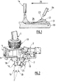
- the Figure 2 schematizes a hybrid MIG-TIG or MAG-TIG welding device, hereinafter referred to as a hybrid welding device, according to one embodiment of the invention.
- the hybrid welding device MIG-TIG or MAG-TIG comprises a welding torch 1 MIG or MAG comprising, at its end facing the parts to be welded, a metal fuse wire la.
- the fuse wire is oriented in a first direction 1b.
- the first direction 1b is perpendicular to the upper surface of said parts.
- the first direction 1b therefore forms an angle of the order of 0 ° with the vertical.
- the hybrid welding device also comprises a TIG welding torch 2 comprising, at its end facing the parts to be welded, a non-fuse electrode 2a.
- the end 2c of the electrode 2a is formed of a tip having a conical sharpening. More specifically, this sharpening generally takes the form of a cone of revolution whose opening angle is between 20 and 40 °, preferably of the order of 30 °.
- the electrode 2a is oriented in a second direction 2b, said first and second directions 1b and 2b being substantially coplanar and forming between them an angle ⁇ of between 5 and 40 °.
- the angle ⁇ is between 10 ° and 30 °, more preferably between 15 ° and 25 °, advantageously between 18 and 23 °, and ideally of the order of 20 °.
- the plane containing the first and second direction 1b and 2b is perpendicular to the surface of the parts to be welded.
- the hybrid welding device further comprises a shoe 5 for assembling the torches 1 and 2 in which they are arranged.
- the welding torch 1 MIG or MAG is arranged in the shoe 5, which shoe 5 is adapted to and designed to allow positioning of the TIG welding torch 2 in at least two predefined positions relative to the torch 1 MIG welding or MAG.
- These at least two predefined positions comprise a first position in which the end 2c of the non-fuse electrode 2a is at a first distance D of the first direction 1b, and a second position in which the end 2c of the electrode non-fuse 2a is located at a second distance D 'of the first direction 1b, the second distance D' being greater than the first distance D.
- Figure 2 illustrates an embodiment in which the TIG welding torch 2 can be arranged in two positions with respect to the MIG or MAG welding torch.
- the distances D and D ' are defined as the distances separating a first point corresponding to the position of the end 2c of the non-fuse electrode 2a and a second point resulting from the orthogonal projection of the first point on the axis defined by the direction 1b.
- the distance D is typically between 20 and 26 mm. These values are particularly advantageous when it is desired to weld stainless steel metal parts. Ideally, for the welding of stainless steel parts, the distance D is of the order of 24 mm.
- the distance D ' is typically between 36 and 44 mm. These values are particularly advantageous when it is desired to weld metal parts of mild steel, i. e. carbon steel. Ideally, for the welding of mild steel parts, the distance D 'is of the order of 40 mm.
- the device of the invention may comprise a shoe 5 allowing additional positions of the torch 2 TIG relative to the torch 1 MIG or MAG.
- the end 2c of the non-fuse electrode 2a can then be positioned at as many additional distances D ", D '" ... as additional positions permitted by the shoe 5.
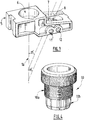
- FIG. Figure 3 The assembly shoe of the hybrid welding device of the invention is illustrated in FIG. Figure 3 without a MIG or MAG welding torch 1 and a TIG welding torch 2 being arranged therein.
- the assembly shoe 5 comprises an axial housing 6 passing through the shoe 5 over its entire thickness in the first direction 1b and opening opposite the metal parts to be welded.
- This axial housing 6 accommodates the welding torch 1 MIG or MAG.
- the axial housing 6 is a passage having a section of cylindrical shape formed in the thickness of the shoe 5.
- the axial housing 6 may include variations in the dimensions of its inside diameter along the first direction 1b, it is that is to say enlargements or narrowing of this diameter, or be of constant inner diameter along the first direction 1b.
- the axial housing 6 may comprise, along all or part of its inner wall, a portion comprising a first thread.
- the end of the torch 1 MIG or MAG provided with the fuse wire la and a nozzle 30 for dispensing the shielding gas protrudes below the shoe 5, that is to say that it is positioned between the shoe 5 and the surface of the metal parts to be welded next to the welding device.
- the assembled shoe 5 comprises means 9 for adjusting in translation the position of the MIG or MAG welding torch 1 along the first direction 1b.
- these translational adjustment means 9 comprise at least one screw that can move in translation in an oblong hole made in a shim placed on the side of the shoe 5. Said shim can slide parallel to the first direction 1b. In this way, the length of the shim protruding below the shoe 5 is adjusted.
- the means 9 allow a precise adjustment of the portion of the end of the torch 1 MIG or MAG protruding from the shoe 5. It is thus possible to adjust the distance between the nozzle 30 equipping the end of the torch 1 MIG or MAG and the metal parts to be welded, this distance constituting one of the parameters of the welding process operated by the device of the invention.
- the hybrid welding device of the invention further comprises a clamp 10 in which is arranged the welding torch 1 MIG or MAG.
- This clamp 10 is itself arranged in the axial housing 6 and serves as an adapter piece for arranging any type of MIG or MAG welding torch 1 in the axial housing 6 of the assembly shoe 5.
- the clamp 10 is schematized on the Figure 4 .
- the clamp 10 is a part of revolution comprising a portion 10a of cylindrical shape whose outer diameter corresponds to the inner diameter of the axial housing 6.
- a second thread is formed on the outer surface of the portion 10a of the clamp 10, the pitch of this second thread being adapted to the pitch of the first thread formed on all or part of the inner wall of the axial housing 6 so that the clamp 10 can be screwed into the axial housing 6.
- the clamp 10 also comprises a portion 10b adapted for and designed to grip and hold the MIG or MAG torch 1.
- the assembled shoe 5 comprises a first lateral housing 7 passing through said shoe 5 in which is arranged the TIG welding torch 2 when it is positioned in the first position.
- the assembly shoe 5 also comprises a second lateral housing 8 passing through the shoe 5 in which the TIG welding torch 2 is arranged when it is positioned in the second position.
- the lateral housings 7 and 8 are passages through the shoe 5 over its entire thickness and opening opposite metal parts to be welded.
- the lateral housings 7 and 8 are passages whose section is of cylindrical shape made in the thickness of the shoe 5.
- the central axes of these passages represented by the discontinuous lines (---) on the Figure, 3 form according to the invention an angle ⁇ with the axis of the axial housing 6 coinciding with the first direction 1b, represented by the continuous line (_).
- the lateral housings 7 and 8 may comprise variations in the dimensions of their inner diameters along their central axes, that is to say enlargements or narrowing of these diameters, or have constant inside diameters along their central axes.
- the lateral housing 7 or the lateral housing 8 may comprise a narrowing of its inner diameter forming a shoulder on which bears at least a portion of the TIG welding torch 2.
- the end of the torch 2 TIG provided with the non-fuse electrode 2a and a nozzle 40 for distribution of the shielding gas also protrudes below the shoe 5, that is to say that it is positioned between the shoe 5 and the surface of the metal parts to be welded next to the welding device.
- the shoe 5 comprises fastening means 11, 13 or 12, 13 of the TIG welding torch 2 in the first or second lateral housings 7, 8.
- the fixing means comprise lateral orifices 11 or 12 in which a screw or a threaded pin 13 can be arranged.
- the pin or the screw 13 is placed in the orifice 11 of the shoe 5 when the torch 2 TIG is positioned in the first position and in the hole 12 of the shoe 5 when the torch 2 TIG is positioned in the second position.
- the pin or the screw 13 passes through the thickness of the shoe 5 in which the orifices 11 and 12 are made and comes to hold the torch 2 TIG.
- the device of the invention comprises a set of spacers allowing the user to adapt any type of TIG torches or MIG or MAG torches in the housing 6, 7 or 8 of the shoe 5.
- the shoe 5 is advantageously formed of a block, in other words the shoe 5 is formed of a single block and not an assembly of parts.
- the housings 6, 7 and 8 are made by machining or drilling in this block.
- the shoe 5 is made of aluminum.
- the invention also relates to a hybrid MIG-TIG or MAG-TIG welding installation comprising a MIG or MAG welding torch 1 and a TIG welding torch 2 electrically connected to at least one current generator.
- the torches 1 and 2 are also fluidly connected to at least one source of gas for supplying the nozzles 30 and 40 with shielding gas.
- the hybrid welding installation MIG-TIG or MAG-TIG comprises a movable beam on which is arranged the hybrid welding device according to the invention.
- Said hybrid welding device may itself be movable or not on the beam.
- the installation also includes a numerical control adapted and adapted to control the displacement of the movable beam and / or the hybrid welding device on said beam.
- the end 2c of the non-fuse electrode 2a is positioned at the rear of the first direction 1b of the fuse wire 1a according to the welding direction and at a distance D or D 'from said first direction 1b chosen according to the nature of the constituent metal of the metal parts to be welded.
- the choice of the distance separating the end 2c of the non-fuse electrode 2a from the first direction 1b is a function of the physical characteristics of the solder bath generated, in particular viscosity and thermal conductivity, which vary according to the nature of the welded material.
- the main application of the present invention is a method of welding metal parts of ferrous alloys, aluminum or aluminum alloy, preferably stainless steel or carbon steel.
- the end 2c of the non-fuse electrode 2a is preferably at the distance D of the first direction 1b.
- the end 2c of the non-fuse electrode (2a) is preferably at a distance D 'from the first direction 1b.
- the electric arc MIG or MAG-TIG and the electric arc TIG are protected by protective gas flows respectively delivered by the nozzles 30 and 40.
- the electric arc MIG or MAG is protected by a gas stream containing mainly at least one inert compound selected from helium and argon, preferably at least 80% (% by volume), and optionally a minor compound having an oxidizing chemical character selected from CO 2 and O 2 .
- the MIG or MAG electric arc is preferably protected by a gas flow containing approximately 98% argon and 2% CO 2 (% by volume).
- a gas stream containing a larger proportion of oxidizing compound for example a gas stream containing about 92% argon and 8% CO 2 or containing 82% of gas, is preferably used. argon and 18% CO 2 (% by volume).
- the electric arc TIG is protected by a flow of gas containing essentially argon, preferably at least 99.9% (% by volume) or a mixture of helium and argon, for example a gas stream containing 80% argon and 20% helium or containing 30% argon and 70% helium, or a mixture containing at least 95% argon and hydrogen (% by volume).
- gas containing essentially argon preferably at least 99.9% (% by volume) or a mixture of helium and argon, for example a gas stream containing 80% argon and 20% helium or containing 30% argon and 70% helium, or a mixture containing at least 95% argon and hydrogen (% by volume).
- the combination of a TIG arc with a MIG or MAG arc is advantageously used to combat the phenomenon of " humping " occurring at high welding speeds.
- the proximity between the two arcs and their rapid succession on one and the same area of the joint make the same joint zone successively hit first by the MIG or MAG arc, then by the TIG arc while the metal of this zone of joint is still liquid, that is to say in fusion after passage of the arc MIG or MAG.
- the TIG arc exerts its action on the welding bath formed by the arc MIG or MAG while it is still liquid.
- the welding bath will then take advantage of the heat flow generated by the TIG arc to not solidify but also the pressure exerted by this arc on the molten metal bump formed at the rear end of this bath, which allows to obtain a weld bead without or almost without bump type defects.
- MIG-TIG hybrid welding tests were carried out on sheets with a thickness of 1.5 mm.
- the invention is particularly advantageous for improving the productivity of a method of welding metal parts having a thickness of less than 3 mm, preferably less than 2 mm, since these thicknesses lead to high welding speeds for which the defect of humping "is most likely to happen.
Landscapes
- Engineering & Computer Science (AREA)
- Mechanical Engineering (AREA)
- Physics & Mathematics (AREA)
- Plasma & Fusion (AREA)
- Chemical & Material Sciences (AREA)
- Materials Engineering (AREA)
- Arc Welding In General (AREA)
Claims (18)
- Hybrid-MIG-TIG- oder MAG-TIG-Schweißvorrichtung, umfassend einen MIG- oder MAG-Schweißbrenner (1), der einen in einer ersten Richtung (1b) ausgerichteten abschmelzenden Schweißdraht (1a) umfasst, der einem WIG-Schweißbrenner (2) zugeordnet ist, der eine nicht schmelzbare Elektrode (2a) umfasst, die in einer zweiten Richtung (2b) ausgerichtet ist, wobei die erste und die zweite Richtung (1b, 2b) im Wesentlichen koplanar sind und zwischen ihnen einen Winkel (α) zwischen 5 und 40 ° bilden,
dadurch gekennzeichnet, dass sie ferner einen Brenner (1, 2) Montageschuh (5) umfasst, der dazu geeignet und ausgelegt ist, den WIG Schweißbrenner (2) in mindestens zwei vordefinierten Positionen in Bezug auf den MIG- oder MAG-Schweißbrenner (1) zu positionieren, und der umfasst:- eine erste Position, in der sich das Ende (2c) der nicht schmelzbaren Elektrode (2a) in einem ersten Abstand (D) von der ersten Richtung (1b) befindet,- mindestens eine zweite Position, in der das Ende (2c) der nicht schmelzbaren Elektrode (2a) sich in einem zweiten Abstand (D') von der ersten Richtung (1b) befindet, wobei der zweite Abstand (D') größer als der erste Abstand (D) ist,- eine axiale Aufnahme (6), die in der ersten Richtung (1b) durch den Schuh (5) verläuft, und in der der MIG- oder MAG-Schweißbrenner (1) angeordnet ist,- eine erste seitliche Aufnahme (7), die durch den Schuh (5) verläuft und in der der WIG-Schweißbrenner (2) angeordnet ist, wenn er in der ersten Position positioniert ist, und- mindestens eine zweite seitliche Aufnahme (8), die durch den Schuh (5) verläuft und in der der WIG-Schweißbrenner (2) angeordnet ist, wenn er in der zweiten Position positioniert ist. - Vorrichtung nach einem der vorhergehenden Ansprüche, dadurch gekennzeichnet, dass der erste Abstand (D) zwischen 20 und 26 mm beträgt.
- Vorrichtung nach einem der vorhergehenden Ansprüche, dadurch gekennzeichnet, dass der zweite Abstand (D') zwischen 36 und 44 mm beträgt.
- Vorrichtung nach einem der vorhergehenden Ansprüche, dadurch gekennzeichnet, dass die erste und die zweite Richtung (1b, 2b) zwischen sich einen Winkel (α) zwischen 10 ° und 30 ° bilden.
- Vorrichtung nach einem der vorhergehenden Ansprüche, dadurch gekennzeichnet, dass der Schuh (5) ferner Befestigungsmittel (11, 13) oder (12, 13) zum Halten des WIG-Schweißbrenners (2) in der ersten oder zweiten seitlichen Aufnahme aufweist (7, 8).
- Vorrichtung nach einem der vorhergehenden Ansprüche, dadurch gekennzeichnet, dass der Schuh (5) ferner eine Einrichtung (9) aufweist, um die Position des MIG- oder MAG-Schweißbrenners (1) entlang der ersten Richtung (1b) translatorisch einzustellen.
- Vorrichtung nach einem der vorhergehenden Ansprüche, dadurch gekennzeichnet, dass sie ferner eine im axialen Gehäuse (6) angeordnete Klammer (10) umfasst, in die der MIG- oder MAG-Schweißbrenner (1) eingesetzt ist.
- Vorrichtung nach einem der vorhergehenden Ansprüche, dadurch gekennzeichnet, dass der Schuh (5) aus einem Block gebildet ist.
- Hybrid-MIG-TIG- oder MAG-TIG-Schweißanordnung, umfassend einen MIG- oder MAG-Schweißbrenner (1) und einen WIG-Schweißbrenner (2), die elektrisch mit mindestens einem Stromgenerator verbunden sind und mit mindestens einer Gasquelle in Fluidverbindung stehen, dadurch gekennzeichnet, dass sie ferner einen beweglichen Träger, auf dem eine Hybrid-MIG-TIG-Schweißvorrichtung nach einem der vorhergehenden Ansprüche angeordnet ist, wobei die MIG-TIG oder MAG-TIG Hybridschweißvorrichtung beweglich ist oder nicht, sowie eine numerische Steuerung umfasst, die geeignet und ausgelegt ist zur Steuerung der Verschiebung des mobilen Trägers und/oder der MIG-TIG- oder MAG-TIG-Hybridschweivorrichtung.
- Verfahren zum Hybrid-MIG-TIG- oder MAG-TIG-Schweißen von Metallteilen (30), dadurch gekennzeichnet, dass eine Hybrid-MIG-TIG- oder MAG-TIG-Schweißvorrichtung nach einem der Ansprüche 1 bis 8 verwendet wird und beim Schweißen:- zwischen dem abschmelzenden Schweißdraht (1a) des MIG- oder MAG-Schweißbrenners (1) und den zu verschweißenden Metallteilen ein MIG- oder MAG-Lichtbogen erzeugt wird, um ein Lötbad zu erzeugen, wobei der MIG- oder MAG-Lichtbogen durch einen Gasstrom geschützt wird, der hauptsächlich mindestens eine inerte Verbindung enthält, ausgewählt aus Helium und Argon, und- ein WIG-Lichtbogen zwischen der nicht-schmelzenden Elektrode (2a) des WIG-Schweißbrenners (2) und den zu verschweißenden Metallteilen an mindestens einem Teil des Lötbads erzeugt wird, wobei der WIG-Lichtbogen durch einen Gasstrom geschützt wird, der hauptsächlich Argon oder eine Mischung aus Helium und Argon enthält.
- Verfahren nach Anspruch 10, dadurch gekennzeichnet, dass der elektrische MIG- oder MAG-Lichtbogen durch einen Gasstrom geschützt wird, der mindestens 80% mindestens einer inerten Verbindung enthält, die aus Helium und Argon (Vol .-%) ausgewählt ist.
- Verfahren nach einem der Ansprüche 10 oder 11, dadurch gekennzeichnet, dass der Gasstrom, der den elektrischen MIG- oder MAG-Lichtbogen schützt, ferner zum geringeren Teil eine chemisch oxidierende Komponente enthält, die aus CO2 und O2 ausgewählt ist.
- Verfahren nach einem der Ansprüche 10 bis 12, dadurch gekennzeichnet, dass, wenn die geschweißten Teile aus Edelstahl bestehen, der den MIG- oder MAG-Lichtbogen schützende Gasstrom etwa 98% Argon und 2% CO2 (Vol .-%) enthält.
- Verfahren nach einem der Ansprüche 10 bis 12, dadurch gekennzeichnet, dass, wenn die geschweißten Teile aus Kohlenstoffstahl gebildet werden, der den MIG- oder MAG-Lichtbogen schützende Gasstrom etwa 92% Argon und 8% CO2 oder 82% Argon und 18% CO2 (Vol.-%) enthält.
- Verfahren nach Anspruch 10, dadurch gekennzeichnet, dass der den TIG-Lichtbogen schützende Gasstrom im Wesentlichen Argon enthält, vorzugsweise mindestens 99,9% Argon (Vol .-%).
- Verfahren nach einem der Ansprüche 10 oder 15, dadurch gekennzeichnet, dass der den WIG-Lichtbogen schützende Gasstrom mindestens 95% Argon und Wasserstoff (Vol .-%) enthält.
- Verfahren nach einem der Ansprüche 10 oder 15, dadurch gekennzeichnet, dass der den WIG-Lichtbogen schützende Gasstrom eine Mischung aus Helium und Argon enthält.
- Verfahren nach einem der Ansprüche 10, 15 oder 17, dadurch gekennzeichnet, dass der den WIG-Lichtbogen schützende Gasstrom enthält:- eine Mischung aus 80% Argon und 20% Helium (Vol .-%),- oder eine Mischung aus 30% Argon und 70% Helium (Vol .-%).
Applications Claiming Priority (2)
| Application Number | Priority Date | Filing Date | Title |
|---|---|---|---|
| FR1250270A FR2985446B1 (fr) | 2012-01-11 | 2012-01-11 | Dispositif de soudage hybride mig-tig ou mag-tig |
| PCT/FR2012/052808 WO2013104839A1 (fr) | 2012-01-11 | 2012-12-05 | Dispositif de soudage hybride mig-tig ou mag-tig |
Publications (2)
| Publication Number | Publication Date |
|---|---|
| EP2802435A1 EP2802435A1 (de) | 2014-11-19 |
| EP2802435B1 true EP2802435B1 (de) | 2019-09-04 |
Family
ID=47505212
Family Applications (1)
| Application Number | Title | Priority Date | Filing Date |
|---|---|---|---|
| EP12810347.0A Not-in-force EP2802435B1 (de) | 2012-01-11 | 2012-12-05 | Mig/wig oder mag/wig hybrid-schweissvorrichtung |
Country Status (4)
| Country | Link |
|---|---|
| US (1) | US20150014284A1 (de) |
| EP (1) | EP2802435B1 (de) |
| FR (1) | FR2985446B1 (de) |
| WO (1) | WO2013104839A1 (de) |
Families Citing this family (8)
| Publication number | Priority date | Publication date | Assignee | Title |
|---|---|---|---|---|
| DE102014002213B4 (de) * | 2014-02-21 | 2016-01-14 | MHIW b.v. | Verfahren und Brennerkopf zum Metall-Schutzgas-Schweißen |
| US20160339533A1 (en) * | 2015-05-18 | 2016-11-24 | Abb Technology Ag | Robotically controlled gas tungsten arc welder and method for operating the same |
| US10307852B2 (en) * | 2016-02-11 | 2019-06-04 | James G. Acquaye | Mobile hardbanding unit |
| US10807179B2 (en) | 2017-02-17 | 2020-10-20 | General Electric Company | Method of build-up welding |
| CN107790886B (zh) * | 2017-09-15 | 2019-09-17 | 哈尔滨工业大学(威海) | 脉动负压式激光增强ktig和mig复合焊接装置及方法 |
| CN108788395A (zh) * | 2018-06-22 | 2018-11-13 | 山东大学 | 一种通过侧壁对称双送丝的一体式tig焊喷嘴及焊枪 |
| CN110434498A (zh) * | 2019-07-24 | 2019-11-12 | 昆山华恒焊接股份有限公司 | 旁轴式复合焊炬 |
| US11738403B2 (en) | 2020-01-27 | 2023-08-29 | The Esab Group Inc. | Push pull torch |
Citations (1)
| Publication number | Priority date | Publication date | Assignee | Title |
|---|---|---|---|---|
| DE2426017A1 (de) * | 1974-05-30 | 1976-03-25 | Materialdata Ab | Brenneranordnung |
Family Cites Families (13)
| Publication number | Priority date | Publication date | Assignee | Title |
|---|---|---|---|---|
| US2623576A (en) * | 1948-01-28 | 1952-12-30 | Shell Dev | Cutting torch with inclined and offset cutting oxygen discharge passage |
| US2591926A (en) * | 1948-07-03 | 1952-04-08 | Air Reduction | Inert gas shielded arc welding method |
| DE1941393U (de) * | 1964-02-18 | 1966-06-30 | Linde Ag | Vorrichtung zum lichtbogenschweissen. |
| GB1188024A (en) * | 1967-04-05 | 1970-04-15 | Welding Inst | Improvements in or relating to Arc Welding Processes and Apparatus. |
| DE4106900A1 (de) * | 1991-03-05 | 1992-09-10 | Messer Griesheim Gmbh | Schutzgas zum wig-, mig-, mag- und plasmaschweissen |
| FR2769863B1 (fr) * | 1997-10-16 | 1999-12-17 | Soudure Autogene Francaise | Procede et dispositif de soudage mig avec modulation du courant |
| FR2809647B1 (fr) * | 2000-05-31 | 2002-08-30 | Air Liquide | Procede de soudage hybride laser-arc avec melange gazeux approprie |
| FR2813544B1 (fr) * | 2000-09-06 | 2002-10-18 | Air Liquide | Procede de soudage mig du nickel et des alliages de nickel avec gaz de protection a base d'argon et de co2 |
| US6693252B2 (en) * | 2002-04-01 | 2004-02-17 | Illinois Tool Works Inc. | Plasma MIG welding with plasma torch and MIG torch |
| US20070007264A1 (en) * | 2005-07-11 | 2007-01-11 | Lincoln Global, Inc. | Hex mount for welding torch |
| WO2007026493A1 (ja) * | 2005-08-31 | 2007-03-08 | Taiyo Nippon Sanso Corporation | ハイブリッド溶接用シールドガスおよび該ガスを用いた溶接方法 |
| DE102007033291A1 (de) * | 2007-07-17 | 2009-01-22 | Linde Ag | Verfahren zum Lichtbogenfügen |
| JP5466484B2 (ja) * | 2009-11-06 | 2014-04-09 | 株式会社神戸製鋼所 | アーク溶接システム、シングルアーク溶接システムおよびタンデムアーク溶接システム |
-
2012
- 2012-01-11 FR FR1250270A patent/FR2985446B1/fr not_active Expired - Fee Related
- 2012-12-05 WO PCT/FR2012/052808 patent/WO2013104839A1/fr not_active Ceased
- 2012-12-05 EP EP12810347.0A patent/EP2802435B1/de not_active Not-in-force
- 2012-12-05 US US14/327,122 patent/US20150014284A1/en not_active Abandoned
Patent Citations (1)
| Publication number | Priority date | Publication date | Assignee | Title |
|---|---|---|---|---|
| DE2426017A1 (de) * | 1974-05-30 | 1976-03-25 | Materialdata Ab | Brenneranordnung |
Also Published As
| Publication number | Publication date |
|---|---|
| FR2985446B1 (fr) | 2014-02-14 |
| WO2013104839A1 (fr) | 2013-07-18 |
| US20150014284A1 (en) | 2015-01-15 |
| EP2802435A1 (de) | 2014-11-19 |
| FR2985446A1 (fr) | 2013-07-12 |
Similar Documents
| Publication | Publication Date | Title |
|---|---|---|
| EP2802435B1 (de) | Mig/wig oder mag/wig hybrid-schweissvorrichtung | |
| EP2605880B1 (de) | Bogenschweissvorrichtung und -verfahren unter verwendung eines mig/mag-brenners in kombination mit einem wig-brenner | |
| EP1736270B2 (de) | WIG-Schweiss- bzw, Lötverfahren mit Metallübertragung durch eine flüssigmetallbrücke | |
| EP1923165A1 (de) | Laserschweißverfahren mit verbesserter Penetration | |
| WO2008015353A1 (fr) | Soudo-brasage tig avec transfert de metal par gouttes a frequence controlee | |
| EP1160046A1 (de) | Anwendung eines hybriden Laser-Lichtbogen-Verfahrens zum Schweissen eines Rohres | |
| EP1427564A1 (de) | Hybridlaser-lichtbogenschweissverfahren mit gassdurchflusseinstellung | |
| CA2517949A1 (fr) | Procede de soudage hybride laser-mig a vitesse de fil elevee | |
| EP1459831A2 (de) | Für einen TIG Roboterschweissbrenner hergestelle Düsen/Drahtführungsanordnung | |
| FR2829415A1 (fr) | Procede d'amorcage de l'arc electrique en soudage hybride laser-arc | |
| EP2313228B1 (de) | Schlackefreier mig/mag-flussmittelkernschweissdraht mit lithium mit einem gas auf co2-basis sowie verfahren zur elektrischen mig/mag-bogenschweissung mit einem solchen schweissdraht | |
| FR2818569A1 (fr) | Procede et dispositif de soudage a l'arc pulse | |
| FR3012759A3 (fr) | Systeme pour et procede de soudage et/ou de rechargement avec fil additionnel | |
| CA2644189C (fr) | Ensemble buse/guide-fil pour torche de soudage tig robotise | |
| FR3010339A1 (fr) | Procede de soudage par faisceau laser sur tole sandwich avec controle de l'ouverture du capillaire | |
| BE1018063A6 (fr) | Automate de soudure et procede de soudure. | |
| FR2986451A1 (fr) | Procede de soudage mig ou mag avec balayage plongeant de la torche | |
| EP1655096B1 (de) | Lichtbogenschweissanlage mit mehreren Brennern mit nichtabschmelzender Elektrode und Zweifach-Fluxschutz für Rohrschweissen, jeder brenner mit der in dem Plan der inneren Düse liegenden Elektrodespitze | |
| EP2590772B1 (de) | Mig/mag-schweissen mit einem drehenden lichtbogen für c-stahl und ar/he/o2 gasmischung | |
| WO2015067882A1 (fr) | Procede de rechargement a l'arc electrique avec protection gazeuse constitue d'un melange gazeux argon/helium | |
| CA2373103A1 (fr) | Procede et installation automatique de soudage multiplasma | |
| FR2974526A1 (fr) | Dispositif et procede de soudage mig/mag | |
| FR2781171A1 (fr) | Buse de soudage a l'arc electrique de diametre et d'epaisseur controles | |
| FR2941160A1 (fr) | Torche de soudage a l'arc des preparations de joints etroits |
Legal Events
| Date | Code | Title | Description |
|---|---|---|---|
| PUAI | Public reference made under article 153(3) epc to a published international application that has entered the european phase |
Free format text: ORIGINAL CODE: 0009012 |
|
| 17P | Request for examination filed |
Effective date: 20140811 |
|
| AK | Designated contracting states |
Kind code of ref document: A1 Designated state(s): AL AT BE BG CH CY CZ DE DK EE ES FI FR GB GR HR HU IE IS IT LI LT LU LV MC MK MT NL NO PL PT RO RS SE SI SK SM TR |
|
| DAX | Request for extension of the european patent (deleted) | ||
| RIN1 | Information on inventor provided before grant (corrected) |
Inventor name: PLANCKAERT, JEAN-PIERRE Inventor name: BURVELLE, NICOLAS |
|
| STAA | Information on the status of an ep patent application or granted ep patent |
Free format text: STATUS: EXAMINATION IS IN PROGRESS |
|
| 17Q | First examination report despatched |
Effective date: 20180511 |
|
| REG | Reference to a national code |
Ref country code: DE Ref legal event code: R079 Ref document number: 602012063699 Country of ref document: DE Free format text: PREVIOUS MAIN CLASS: B23K0009280000 Ipc: B23K0009230000 |
|
| GRAP | Despatch of communication of intention to grant a patent |
Free format text: ORIGINAL CODE: EPIDOSNIGR1 |
|
| STAA | Information on the status of an ep patent application or granted ep patent |
Free format text: STATUS: GRANT OF PATENT IS INTENDED |
|
| RIC1 | Information provided on ipc code assigned before grant |
Ipc: B23K 35/38 20060101ALI20190304BHEP Ipc: B23K 9/28 20060101ALI20190304BHEP Ipc: B23K 9/173 20060101ALI20190304BHEP Ipc: B23K 9/167 20060101ALI20190304BHEP Ipc: B23K 9/23 20060101AFI20190304BHEP |
|
| INTG | Intention to grant announced |
Effective date: 20190321 |
|
| GRAS | Grant fee paid |
Free format text: ORIGINAL CODE: EPIDOSNIGR3 |
|
| RAP1 | Party data changed (applicant data changed or rights of an application transferred) |
Owner name: LINCOLN ELECTRIC FRANCE SAS |
|
| GRAA | (expected) grant |
Free format text: ORIGINAL CODE: 0009210 |
|
| STAA | Information on the status of an ep patent application or granted ep patent |
Free format text: STATUS: THE PATENT HAS BEEN GRANTED |
|
| AK | Designated contracting states |
Kind code of ref document: B1 Designated state(s): AL AT BE BG CH CY CZ DE DK EE ES FI FR GB GR HR HU IE IS IT LI LT LU LV MC MK MT NL NO PL PT RO RS SE SI SK SM TR |
|
| REG | Reference to a national code |
Ref country code: GB Ref legal event code: FG4D Free format text: NOT ENGLISH |
|
| REG | Reference to a national code |
Ref country code: CH Ref legal event code: EP |
|
| REG | Reference to a national code |
Ref country code: AT Ref legal event code: REF Ref document number: 1174675 Country of ref document: AT Kind code of ref document: T Effective date: 20190915 |
|
| REG | Reference to a national code |
Ref country code: DE Ref legal event code: R096 Ref document number: 602012063699 Country of ref document: DE Ref country code: IE Ref legal event code: FG4D Free format text: LANGUAGE OF EP DOCUMENT: FRENCH |
|
| REG | Reference to a national code |
Ref country code: NL Ref legal event code: MP Effective date: 20190904 |
|
| REG | Reference to a national code |
Ref country code: LT Ref legal event code: MG4D |
|
| PG25 | Lapsed in a contracting state [announced via postgrant information from national office to epo] |
Ref country code: HR Free format text: LAPSE BECAUSE OF FAILURE TO SUBMIT A TRANSLATION OF THE DESCRIPTION OR TO PAY THE FEE WITHIN THE PRESCRIBED TIME-LIMIT Effective date: 20190904 Ref country code: LT Free format text: LAPSE BECAUSE OF FAILURE TO SUBMIT A TRANSLATION OF THE DESCRIPTION OR TO PAY THE FEE WITHIN THE PRESCRIBED TIME-LIMIT Effective date: 20190904 Ref country code: BG Free format text: LAPSE BECAUSE OF FAILURE TO SUBMIT A TRANSLATION OF THE DESCRIPTION OR TO PAY THE FEE WITHIN THE PRESCRIBED TIME-LIMIT Effective date: 20191204 Ref country code: SE Free format text: LAPSE BECAUSE OF FAILURE TO SUBMIT A TRANSLATION OF THE DESCRIPTION OR TO PAY THE FEE WITHIN THE PRESCRIBED TIME-LIMIT Effective date: 20190904 Ref country code: FI Free format text: LAPSE BECAUSE OF FAILURE TO SUBMIT A TRANSLATION OF THE DESCRIPTION OR TO PAY THE FEE WITHIN THE PRESCRIBED TIME-LIMIT Effective date: 20190904 Ref country code: NO Free format text: LAPSE BECAUSE OF FAILURE TO SUBMIT A TRANSLATION OF THE DESCRIPTION OR TO PAY THE FEE WITHIN THE PRESCRIBED TIME-LIMIT Effective date: 20191204 |
|
| PG25 | Lapsed in a contracting state [announced via postgrant information from national office to epo] |
Ref country code: RS Free format text: LAPSE BECAUSE OF FAILURE TO SUBMIT A TRANSLATION OF THE DESCRIPTION OR TO PAY THE FEE WITHIN THE PRESCRIBED TIME-LIMIT Effective date: 20190904 Ref country code: LV Free format text: LAPSE BECAUSE OF FAILURE TO SUBMIT A TRANSLATION OF THE DESCRIPTION OR TO PAY THE FEE WITHIN THE PRESCRIBED TIME-LIMIT Effective date: 20190904 Ref country code: GR Free format text: LAPSE BECAUSE OF FAILURE TO SUBMIT A TRANSLATION OF THE DESCRIPTION OR TO PAY THE FEE WITHIN THE PRESCRIBED TIME-LIMIT Effective date: 20191205 Ref country code: AL Free format text: LAPSE BECAUSE OF FAILURE TO SUBMIT A TRANSLATION OF THE DESCRIPTION OR TO PAY THE FEE WITHIN THE PRESCRIBED TIME-LIMIT Effective date: 20190904 |
|
| REG | Reference to a national code |
Ref country code: AT Ref legal event code: MK05 Ref document number: 1174675 Country of ref document: AT Kind code of ref document: T Effective date: 20190904 |
|
| PG25 | Lapsed in a contracting state [announced via postgrant information from national office to epo] |
Ref country code: RO Free format text: LAPSE BECAUSE OF FAILURE TO SUBMIT A TRANSLATION OF THE DESCRIPTION OR TO PAY THE FEE WITHIN THE PRESCRIBED TIME-LIMIT Effective date: 20190904 Ref country code: IT Free format text: LAPSE BECAUSE OF FAILURE TO SUBMIT A TRANSLATION OF THE DESCRIPTION OR TO PAY THE FEE WITHIN THE PRESCRIBED TIME-LIMIT Effective date: 20190904 Ref country code: PT Free format text: LAPSE BECAUSE OF FAILURE TO SUBMIT A TRANSLATION OF THE DESCRIPTION OR TO PAY THE FEE WITHIN THE PRESCRIBED TIME-LIMIT Effective date: 20200106 Ref country code: EE Free format text: LAPSE BECAUSE OF FAILURE TO SUBMIT A TRANSLATION OF THE DESCRIPTION OR TO PAY THE FEE WITHIN THE PRESCRIBED TIME-LIMIT Effective date: 20190904 Ref country code: AT Free format text: LAPSE BECAUSE OF FAILURE TO SUBMIT A TRANSLATION OF THE DESCRIPTION OR TO PAY THE FEE WITHIN THE PRESCRIBED TIME-LIMIT Effective date: 20190904 Ref country code: NL Free format text: LAPSE BECAUSE OF FAILURE TO SUBMIT A TRANSLATION OF THE DESCRIPTION OR TO PAY THE FEE WITHIN THE PRESCRIBED TIME-LIMIT Effective date: 20190904 Ref country code: PL Free format text: LAPSE BECAUSE OF FAILURE TO SUBMIT A TRANSLATION OF THE DESCRIPTION OR TO PAY THE FEE WITHIN THE PRESCRIBED TIME-LIMIT Effective date: 20190904 |
|
| PG25 | Lapsed in a contracting state [announced via postgrant information from national office to epo] |
Ref country code: SK Free format text: LAPSE BECAUSE OF FAILURE TO SUBMIT A TRANSLATION OF THE DESCRIPTION OR TO PAY THE FEE WITHIN THE PRESCRIBED TIME-LIMIT Effective date: 20190904 Ref country code: IS Free format text: LAPSE BECAUSE OF FAILURE TO SUBMIT A TRANSLATION OF THE DESCRIPTION OR TO PAY THE FEE WITHIN THE PRESCRIBED TIME-LIMIT Effective date: 20200224 Ref country code: SM Free format text: LAPSE BECAUSE OF FAILURE TO SUBMIT A TRANSLATION OF THE DESCRIPTION OR TO PAY THE FEE WITHIN THE PRESCRIBED TIME-LIMIT Effective date: 20190904 Ref country code: CZ Free format text: LAPSE BECAUSE OF FAILURE TO SUBMIT A TRANSLATION OF THE DESCRIPTION OR TO PAY THE FEE WITHIN THE PRESCRIBED TIME-LIMIT Effective date: 20190904 |
|
| REG | Reference to a national code |
Ref country code: DE Ref legal event code: R097 Ref document number: 602012063699 Country of ref document: DE |
|
| REG | Reference to a national code |
Ref country code: DE Ref legal event code: R119 Ref document number: 602012063699 Country of ref document: DE |
|
| PLBE | No opposition filed within time limit |
Free format text: ORIGINAL CODE: 0009261 |
|
| STAA | Information on the status of an ep patent application or granted ep patent |
Free format text: STATUS: NO OPPOSITION FILED WITHIN TIME LIMIT |
|
| PG2D | Information on lapse in contracting state deleted |
Ref country code: IS |
|
| PG25 | Lapsed in a contracting state [announced via postgrant information from national office to epo] |
Ref country code: DK Free format text: LAPSE BECAUSE OF FAILURE TO SUBMIT A TRANSLATION OF THE DESCRIPTION OR TO PAY THE FEE WITHIN THE PRESCRIBED TIME-LIMIT Effective date: 20190904 Ref country code: IS Free format text: LAPSE BECAUSE OF FAILURE TO SUBMIT A TRANSLATION OF THE DESCRIPTION OR TO PAY THE FEE WITHIN THE PRESCRIBED TIME-LIMIT Effective date: 20200105 |
|
| REG | Reference to a national code |
Ref country code: CH Ref legal event code: PL |
|
| 26N | No opposition filed |
Effective date: 20200605 |
|
| REG | Reference to a national code |
Ref country code: BE Ref legal event code: MM Effective date: 20191231 |
|
| PG25 | Lapsed in a contracting state [announced via postgrant information from national office to epo] |
Ref country code: MC Free format text: LAPSE BECAUSE OF FAILURE TO SUBMIT A TRANSLATION OF THE DESCRIPTION OR TO PAY THE FEE WITHIN THE PRESCRIBED TIME-LIMIT Effective date: 20190904 Ref country code: SI Free format text: LAPSE BECAUSE OF FAILURE TO SUBMIT A TRANSLATION OF THE DESCRIPTION OR TO PAY THE FEE WITHIN THE PRESCRIBED TIME-LIMIT Effective date: 20190904 |
|
| GBPC | Gb: european patent ceased through non-payment of renewal fee |
Effective date: 20191205 |
|
| PG25 | Lapsed in a contracting state [announced via postgrant information from national office to epo] |
Ref country code: LU Free format text: LAPSE BECAUSE OF NON-PAYMENT OF DUE FEES Effective date: 20191205 Ref country code: IE Free format text: LAPSE BECAUSE OF NON-PAYMENT OF DUE FEES Effective date: 20191205 Ref country code: FR Free format text: LAPSE BECAUSE OF NON-PAYMENT OF DUE FEES Effective date: 20191231 Ref country code: GB Free format text: LAPSE BECAUSE OF NON-PAYMENT OF DUE FEES Effective date: 20191205 Ref country code: DE Free format text: LAPSE BECAUSE OF NON-PAYMENT OF DUE FEES Effective date: 20200701 Ref country code: ES Free format text: LAPSE BECAUSE OF FAILURE TO SUBMIT A TRANSLATION OF THE DESCRIPTION OR TO PAY THE FEE WITHIN THE PRESCRIBED TIME-LIMIT Effective date: 20190904 |
|
| PG25 | Lapsed in a contracting state [announced via postgrant information from national office to epo] |
Ref country code: CH Free format text: LAPSE BECAUSE OF NON-PAYMENT OF DUE FEES Effective date: 20191231 Ref country code: LI Free format text: LAPSE BECAUSE OF NON-PAYMENT OF DUE FEES Effective date: 20191231 Ref country code: BE Free format text: LAPSE BECAUSE OF NON-PAYMENT OF DUE FEES Effective date: 20191231 |
|
| PG25 | Lapsed in a contracting state [announced via postgrant information from national office to epo] |
Ref country code: CY Free format text: LAPSE BECAUSE OF FAILURE TO SUBMIT A TRANSLATION OF THE DESCRIPTION OR TO PAY THE FEE WITHIN THE PRESCRIBED TIME-LIMIT Effective date: 20190904 |
|
| PG25 | Lapsed in a contracting state [announced via postgrant information from national office to epo] |
Ref country code: HU Free format text: LAPSE BECAUSE OF FAILURE TO SUBMIT A TRANSLATION OF THE DESCRIPTION OR TO PAY THE FEE WITHIN THE PRESCRIBED TIME-LIMIT; INVALID AB INITIO Effective date: 20121205 Ref country code: MT Free format text: LAPSE BECAUSE OF FAILURE TO SUBMIT A TRANSLATION OF THE DESCRIPTION OR TO PAY THE FEE WITHIN THE PRESCRIBED TIME-LIMIT Effective date: 20190904 |
|
| PG25 | Lapsed in a contracting state [announced via postgrant information from national office to epo] |
Ref country code: TR Free format text: LAPSE BECAUSE OF FAILURE TO SUBMIT A TRANSLATION OF THE DESCRIPTION OR TO PAY THE FEE WITHIN THE PRESCRIBED TIME-LIMIT Effective date: 20190904 |
|
| PG25 | Lapsed in a contracting state [announced via postgrant information from national office to epo] |
Ref country code: MK Free format text: LAPSE BECAUSE OF FAILURE TO SUBMIT A TRANSLATION OF THE DESCRIPTION OR TO PAY THE FEE WITHIN THE PRESCRIBED TIME-LIMIT Effective date: 20190904 |