EP1654495B1 - Hitzeschildanordnung für eine ein heissgas führende komponente, insbesondere für eine brennkammer einer gasturbine - Google Patents
Hitzeschildanordnung für eine ein heissgas führende komponente, insbesondere für eine brennkammer einer gasturbine Download PDFInfo
- Publication number
- EP1654495B1 EP1654495B1 EP04763361.5A EP04763361A EP1654495B1 EP 1654495 B1 EP1654495 B1 EP 1654495B1 EP 04763361 A EP04763361 A EP 04763361A EP 1654495 B1 EP1654495 B1 EP 1654495B1
- Authority
- EP
- European Patent Office
- Prior art keywords
- heat shield
- coolant
- cooling
- combustion chamber
- hot gas
- Prior art date
- Legal status (The legal status is an assumption and is not a legal conclusion. Google has not performed a legal analysis and makes no representation as to the accuracy of the status listed.)
- Active
Links
- 238000002485 combustion reaction Methods 0.000 title claims description 44
- 238000001816 cooling Methods 0.000 claims description 64
- 239000002826 coolant Substances 0.000 claims description 56
- 238000007789 sealing Methods 0.000 claims description 16
- 229910052751 metal Inorganic materials 0.000 claims description 6
- 239000002184 metal Substances 0.000 claims description 6
- 229910001092 metal group alloy Inorganic materials 0.000 claims description 6
- 238000013017 mechanical damping Methods 0.000 claims description 2
- 238000007599 discharging Methods 0.000 claims 1
- 239000012809 cooling fluid Substances 0.000 description 20
- XEEYBQQBJWHFJM-UHFFFAOYSA-N Iron Chemical compound [Fe] XEEYBQQBJWHFJM-UHFFFAOYSA-N 0.000 description 4
- PXHVJJICTQNCMI-UHFFFAOYSA-N Nickel Chemical compound [Ni] PXHVJJICTQNCMI-UHFFFAOYSA-N 0.000 description 4
- 239000003779 heat-resistant material Substances 0.000 description 4
- 238000007664 blowing Methods 0.000 description 3
- 229910010293 ceramic material Inorganic materials 0.000 description 3
- 239000003344 environmental pollutant Substances 0.000 description 3
- 231100000719 pollutant Toxicity 0.000 description 3
- VYZAMTAEIAYCRO-UHFFFAOYSA-N Chromium Chemical compound [Cr] VYZAMTAEIAYCRO-UHFFFAOYSA-N 0.000 description 2
- 230000000903 blocking effect Effects 0.000 description 2
- 238000005266 casting Methods 0.000 description 2
- 229910052804 chromium Inorganic materials 0.000 description 2
- 239000011651 chromium Substances 0.000 description 2
- 229910017052 cobalt Inorganic materials 0.000 description 2
- 239000010941 cobalt Substances 0.000 description 2
- GUTLYIVDDKVIGB-UHFFFAOYSA-N cobalt atom Chemical compound [Co] GUTLYIVDDKVIGB-UHFFFAOYSA-N 0.000 description 2
- 230000000694 effects Effects 0.000 description 2
- 238000009434 installation Methods 0.000 description 2
- 229910052742 iron Inorganic materials 0.000 description 2
- 239000000463 material Substances 0.000 description 2
- 238000000034 method Methods 0.000 description 2
- 229910052759 nickel Inorganic materials 0.000 description 2
- 235000001674 Agaricus brunnescens Nutrition 0.000 description 1
- 229910000831 Steel Inorganic materials 0.000 description 1
- 230000004888 barrier function Effects 0.000 description 1
- 230000015572 biosynthetic process Effects 0.000 description 1
- 239000000919 ceramic Substances 0.000 description 1
- 238000013016 damping Methods 0.000 description 1
- 230000007423 decrease Effects 0.000 description 1
- 230000001419 dependent effect Effects 0.000 description 1
- 230000001627 detrimental effect Effects 0.000 description 1
- 238000011161 development Methods 0.000 description 1
- 230000018109 developmental process Effects 0.000 description 1
- 238000005315 distribution function Methods 0.000 description 1
- 238000005516 engineering process Methods 0.000 description 1
- 230000002349 favourable effect Effects 0.000 description 1
- 239000012530 fluid Substances 0.000 description 1
- 239000000446 fuel Substances 0.000 description 1
- 239000007788 liquid Substances 0.000 description 1
- 238000004519 manufacturing process Methods 0.000 description 1
- 150000002739 metals Chemical class 0.000 description 1
- 230000035515 penetration Effects 0.000 description 1
- 230000000630 rising effect Effects 0.000 description 1
- 239000010959 steel Substances 0.000 description 1
- 230000000930 thermomechanical effect Effects 0.000 description 1
Images


Classifications
-
- F—MECHANICAL ENGINEERING; LIGHTING; HEATING; WEAPONS; BLASTING
- F23—COMBUSTION APPARATUS; COMBUSTION PROCESSES
- F23R—GENERATING COMBUSTION PRODUCTS OF HIGH PRESSURE OR HIGH VELOCITY, e.g. GAS-TURBINE COMBUSTION CHAMBERS
- F23R3/00—Continuous combustion chambers using liquid or gaseous fuel
- F23R3/002—Wall structures
-
- F—MECHANICAL ENGINEERING; LIGHTING; HEATING; WEAPONS; BLASTING
- F23—COMBUSTION APPARATUS; COMBUSTION PROCESSES
- F23M—CASINGS, LININGS, WALLS OR DOORS SPECIALLY ADAPTED FOR COMBUSTION CHAMBERS, e.g. FIREBRIDGES; DEVICES FOR DEFLECTING AIR, FLAMES OR COMBUSTION PRODUCTS IN COMBUSTION CHAMBERS; SAFETY ARRANGEMENTS SPECIALLY ADAPTED FOR COMBUSTION APPARATUS; DETAILS OF COMBUSTION CHAMBERS, NOT OTHERWISE PROVIDED FOR
- F23M5/00—Casings; Linings; Walls
- F23M5/02—Casings; Linings; Walls characterised by the shape of the bricks or blocks used
-
- F—MECHANICAL ENGINEERING; LIGHTING; HEATING; WEAPONS; BLASTING
- F23—COMBUSTION APPARATUS; COMBUSTION PROCESSES
- F23M—CASINGS, LININGS, WALLS OR DOORS SPECIALLY ADAPTED FOR COMBUSTION CHAMBERS, e.g. FIREBRIDGES; DEVICES FOR DEFLECTING AIR, FLAMES OR COMBUSTION PRODUCTS IN COMBUSTION CHAMBERS; SAFETY ARRANGEMENTS SPECIALLY ADAPTED FOR COMBUSTION APPARATUS; DETAILS OF COMBUSTION CHAMBERS, NOT OTHERWISE PROVIDED FOR
- F23M5/00—Casings; Linings; Walls
- F23M5/08—Cooling thereof; Tube walls
- F23M5/085—Cooling thereof; Tube walls using air or other gas as the cooling medium
-
- F—MECHANICAL ENGINEERING; LIGHTING; HEATING; WEAPONS; BLASTING
- F23—COMBUSTION APPARATUS; COMBUSTION PROCESSES
- F23R—GENERATING COMBUSTION PRODUCTS OF HIGH PRESSURE OR HIGH VELOCITY, e.g. GAS-TURBINE COMBUSTION CHAMBERS
- F23R2900/00—Special features of, or arrangements for continuous combustion chambers; Combustion processes therefor
- F23R2900/00012—Details of sealing devices
Definitions
- the invention relates to a heat shield assembly for a component carrying a hot gas, which comprises a plurality of heat shield elements arranged next to one another on a support structure while leaving a gap, wherein a heat shield element can be attached to the support structure, so that an interior is formed that is partially cooled by one Hot gas wall is limited, with an inlet channel for the flow of a coolant in the interior.
- the invention further relates to a combustion chamber with an inner combustion liner, which has such a heat shield assembly and a gas turbine with such a combustion chamber.
- the heat shield assembly serves to protect a support structure against a hot fluid, in particular for Protection of a hot gas duct wall in gas turbine plants.
- the heat shield assembly has an inner lining made of heat-resistant material, which is composed over the entire area of heat shield elements anchored to the supporting structure. These heat shield elements are arranged side by side, leaving columns for the flow of cooling fluid and heat-mobile.
- Each of these heat shield elements has a hat part and a shaft part in the manner of a mushroom.
- the hat part is a flat or spatial polygonal plate body with straight or curved boundary lines.
- the shank part connects the central region of the plate body with the support structure.
- the hat part preferably has a triangular shape, whereby an inner lining of almost any geometry can be produced by identical hat parts.
- the hat parts and possibly other parts of the heat shield elements are made of a highly heat-resistant material, in particular of a steel.
- the support structure has bores through which a cooling fluid, in particular air, can flow into an intermediate space between the hat part and support structure and from there can flow through the gaps for the flow of the cooling fluid into a space area surrounded by the heat shield elements, for example a combustion chamber of a gas turbine plant. This cooling fluid flow reduces the penetration of hot gas into the gap.
- a metallic lining for a combustion chamber is described.
- This lining consists of a plurality of cube-shaped hollow components (cells) arranged next to one another, which are welded or soldered to a common metal plate.
- the common metal plate has each cube-shaped cell associated with exactly one opening for the inflow of cooling fluid.
- the cube-shaped cells are each arranged side by side leaving a gap. They include on each side wall in the vicinity of the common metal plate, a respective opening for the outflow of cooling fluid.
- the cooling fluid thus passes into the gaps between adjacent cube-shaped cells, flows through this column and forms on a hot gas exposable, parallel to the metallic plate surface of the cells, a cooling film.
- an open cooling system is defined, in which cooling air over a wall structure through the cells in the inside of the combustion chamber into it. The cooling air is therefore lost for further cooling purposes.
- the wall in particular for gas turbine plants, described having cooling fluid channels.
- the wall is preferably arranged in gas turbine installations between a hot room and a cooling fluid space. It is assembled from individual wall elements, wherein each of the wall elements is a made of heat-resistant material plate body. Each plate body has distributed over its base, mutually parallel cooling channels communicating at one end with a cooling fluid space and at the other end with the hot room. The cooling fluid flowing into the hot space and guided through the cooling fluid channels forms a cooling fluid film on the surface of the wall element facing the hot space and / or adjacent wall elements.
- a cooling system for cooling a combustion chamber wall is shown.
- the combustion chamber wall is formed by wall elements.
- Each wall element has a hot gas wall with a hot gas-acted outside and with an inside. Perpendicular to the inside nozzles are arranged. From these nozzles, cooling fluid emerges in the form of a concentrated stream and impinges on the inside. As a result, the hot gas wall is cooled.
- the cooling fluid is collected in a collection chamber and discharged from the collection chamber.
- all these heat shield arrangements are based on the principle that compressor air is used as the cooling medium for the combustion chamber and its lining, and as sealing air.
- the Cooling and sealing air enters the combustion chamber without having participated in the combustion. This cold air mixes with the hot gas. This reduces the temperature at the combustion chamber outlet. Therefore, the performance of the gas turbine and the efficiency of the thermodynamic process decreases.
- the compensation can be partly done by setting a higher flame temperature. However, this results in material problems and higher emission levels must be accepted.
- Another disadvantage of the stated arrangements is that arise by the entry of a significant cooling fluid mass flow into the combustion chamber at the burner air supplied pressure losses.
- the object of the invention is to provide a heat shield arrangement that can be cooled with a coolant, so that when cooling the heat shield arrangement at most a small loss of cooling fluid occurs.
- the heat shield assembly should be usable in a combustion chamber of a gas turbine.
- the invention is based on the consideration that due to the very high flame temperatures in hot gas ducts or other hot gas spaces, for example in combustion chambers of stationary gas turbines, the hot gas leading components must be actively cooled.
- a variety of cooling technologies - also in combination - can be used.
- the most commonly used cooling concepts are convection cooling, convection cooling with turbulence-increasing measures and impingement cooling. Due to the very intensive efforts, in particular, to reduce the pollutant emissions of open-cooled systems, for example of open-cooled combustors of gas turbines, the saving of cooling air is a particularly important factor in achieving these goals - here an increased NO x reduction.
- the goal for open-cooled cooling concepts is therefore to minimize the required cooling air mass flow.
- the cooling air finally escapes through the gap of adjacent heat shield elements after the cooling task has ended, in order subsequently to reach the combustion chamber.
- the outflow of cooling air protects the system from hot gas entering the gap.
- the uncontrolled blowing out of the cooling air however, more cooling air is used to lock the column, as required for the cooling task. This overdose results in excessive cooling air consumption with detrimental consequences for the overall system efficiency and pollutant emissions of the hot gas generating combustion system.
- the heat shield arrangement is special easy to implement and compared to the closed cooling concepts with coolant return constructively associated with significantly lower manufacturing costs. Due to the controlled coolant outlet into the gap can be compared to the conventional concepts coolant, for. As cooling air, can be saved and at the same time a significant reduction in pollutant emissions are effected, in particular the NO x emission. This is achieved in that a coolant outlet channel is provided for the controlled exit of coolant from the interior, which opens from the interior into the gap.
- a particularly high cooling efficiency and blocking effect of the coolant against a hot gas attack in the gap on the support structure is thereby achieved in the gap by the targeted and metered admission of the gap with coolant.
- the controlled exit of coolant from the interior can be made in a simple manner by appropriate dimensioning of the coolant outlet channel, for example with regard to the channel cross-section and the channel length.
- the heat shield element on a side wall which is inclined relative to the hot gas wall in the direction of the support structure.
- the heat shield element is formed in its basic geometry as a single-shell hollow body, which is attachable to the support structure, wherein the interior space is formed.
- the interior is bounded or fixed in exactly one direction by the support structure and in the other spatial directions by the heat shield element itself.
- the coolant outlet passage penetrates the side wall.
- the coolant outlet channel can be designed simply as a bore through the side wall, wherein the interior is connected to the gap formed by the gap.
- coolant may be due the pressure difference between the interior and the gap defined by the gap in a controlled manner from the interior through the coolant outlet channel emerge.
- a sealing element is mounted between the side wall and the support structure. Due to the inclination of the side wall in the direction of the support structure, a gap can be provided for releasable attachment of the heat shield element to the support structure for thermo-mechanical reasons, which can lead to undesirable coolant leaks. Therefore, it is particularly advantageous to seal any gaps, which can lead to an uncontrolled blowing out of coolant from the interior, by suitable sealing measures. As a result, a tight connection between the heat shield element and the support structure is provided.
- the sealing element between the side wall and the support structure is a particularly simple but effective measure to further reduce the coolant consumption.
- the sealing element can additionally assume a damping function, so that the heat shield elements of the heat shield arrangement are mechanically damped on the support structure.
- the interior of a heat shield element is assigned an impact cooling device, so that the hot gas wall can be cooled by means of impingement cooling.
- the impingement cooling is a particularly effective method of cooling the heat shield assembly, the coolant impinges on the hot gas wall in a plurality of discrete coolant jets perpendicular to the hot gas wall and efficiently cools the hot gas wall in accordance with the interior.
- the impact cooling device is formed by a plurality of inlet channels for coolant, which are introduced into the support structure.
- a corresponding multiplicity of inlet ducts which enter into an interior of a Open heat shield element, an impact cooling device is already realized in a simple manner.
- the support structure in addition to the function of supporting the heat shield assembly, has at the same time a coolant distribution function through the plurality of inlet channels for the coolant introduced into the support structure.
- the inlet channels can be designed as holes in the wall of the support structure.
- the heat shield element consists of a metal or a metal alloy.
- high-temperature-resistant metallic alloys based on iron, chromium, nickel or cobalt are suitable for this purpose. Since metals or metal alloys are well suited for a casting process, the heat shield element is advantageously designed as a casting.
- the heat shield assembly is in a particularly preferred embodiment suitable for use in a combustion chamber lining a combustion chamber.
- a combustion chamber provided with a heat shield arrangement is preferably suitable as a combustion chamber of a gas turbine, in particular of a stationary gas turbine.
- the gas turbine 1 has a compressor 2 for the combustion air, a combustion chamber 4 and a turbine 6 for driving a compressor 2 and a generator, not shown, or a working machine.
- the turbine 6 and the compressor 2 are arranged on a common, also called turbine rotor turbine shaft 8, with which the generator or the working machine is connected, and which is rotatably mounted about its central axis 9.
- the running in the manner of an annular combustion chamber 4 is equipped with a number of burners 10 for the combustion of a liquid or gaseous fuel.
- the turbine 6 has a number of rotatable blades 12 connected to the turbine shaft 8.
- the blades 12 are arranged in a ring on the turbine shaft 8 and thus form a number of blade rows.
- the turbine 6 comprises a number of fixed vanes 14, which are also fixed in a ring shape with the formation of rows of vanes on an inner casing 16 of the turbine 6.
- the blades 12 serve to drive the turbine shaft by momentum transfer from the hot medium flowing through the turbine 6, the working medium or the hot gas M.
- the vanes 14 serve to guide the flow of the working medium M between two successive blade rows or blade rows seen in the flow direction of the working medium M.
- a successive pair of a ring of vanes 14 or a vane 3 and a ring of blades 12 or a blade row is also referred to as a turbine stage.
- Each vane 14 has a platform 18, also referred to as a blade root, which is arranged to fix the respective vane 14 on the inner housing 16 of the turbine 6 as a wall element.
- the platform 18 is a thermally comparatively heavily loaded component, which forms the outer boundary of a hot gas channel for the working medium M flowing through the turbine 6.
- Each blade 12 is attached to the turbine shaft 8 in an analogous manner via a platform 20, also referred to as a blade root.
- each guide ring 21 on the inner housing 16 of the turbine 6 is arranged between the spaced-apart platforms 18 of the guide vanes 14 of two adjacent rows of guide vanes.
- the outer surface of each guide ring 21 is also exposed to the hot, the turbine 6 flowing through the working medium M and spaced in the radial direction from the outer end 22 of the blade 12 opposite it through a gap.
- the guide rings 21 arranged between adjacent guide blade rows serve, in particular, as cover elements which protect the inner wall 16 or other housing installation parts from thermal overload by the hot working medium M, the hot gas, flowing through the turbine 6.
- the combustion chamber 4 is delimited by a combustion chamber housing 29, wherein a combustion chamber wall 24 is formed on the combustion chamber side.
- the combustion chamber 4 is designed as a so-called annular combustion chamber, in whose plurality of burners 10 arranged around the turbine shaft 8 in the circumferential direction open into a common combustion chamber space.
- the combustion chamber 4 is configured in its entirety as an annular structure which is positioned around the turbine shaft 8 around.
- the combustion chamber is designed for a comparatively high temperature of the working medium M of about 1200 ° C to 1500 ° C.
- the combustion chamber wall 24 is provided on its side facing the working medium M side with a heat shield assembly 26 which forms a combustion chamber lining. Due to the high temperatures inside the combustion chamber 4, a cooling system is also provided for the heat shield assembly 26.
- the cooling system is based on the principle of impingement cooling, in which the cooling air is blown as coolant K under sufficiently high pressure at a plurality of points to the cooling component perpendicular to its component surface under pressure.
- the cooling system can also be based on the principle of convective cooling or make use of this cooling principle in addition to the impingement cooling.
- the cooling system is designed with a simple structure for a reliable, comprehensive coverage of the heat shield assembly with coolant K and also to a very low coolant consumption.
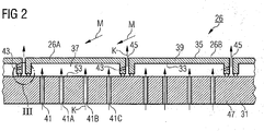
- FIG. 2 a heat shield assembly 26, as it is particularly suitable for use as a heat-resistant lining of a combustion chamber 4 of a gas turbine 1.
- the heat shield arrangement 26 comprises heat shield elements 26A, 26B, which are arranged next to one another on a support structure 31, leaving a gap 45.
- the heat shield elements 26A, 26B have a hot gas wall 39 to be cooled, which has a hot side 35 facing the hot gas M and acted upon by the hot gas M during operation, and a cold side 33 opposite the hot side 35.
- the heat shield elements 26A, 26B are produced from their cold side 33 by a coolant K, for example cooling air, cooled, which is delivered to the interior 37 formed between the heat shield elements 26A, 26B and the support structure 31 by suitable inlet channels 41, 41A, 41B, 41C and in a direction perpendicular to the cold side 33 of a respective heat shield element 26A, 26B is passed.
- a coolant K for example cooling air
- the principle of open cooling is used.
- the at least partially heated air is added to the hot gas M.
- a coolant outlet channel 43 is provided, which opens from the interior 37 into the gap 45.
- the gap 45 is a precisely predetermined mass flow of coolant K deliverable.
- the plurality of inlet channels 41, 41A, 41B, 41C which are each assigned to an interior space 37 of a respective heat shield element 26A, 26B, form an impingement cooling device 53, so that the hot gas wall 39 can be cooled particularly effectively by means of impingement cooling.
- the inlet channels 41, 41A, 41B, 41C for the coolant K are here introduced through corresponding holes in the wall 47 of the support structure.
- the inlet channels 41, 41A, 41B, 41C open into the interior 37 in such a way that a vertical admission of the hot gas wall 39 is achieved.
- the coolant K flows from the interior space 37 in a controlled manner through the correspondingly dimensioned coolant outlet channel 43 into the gap 45, where a barrier effect against the hot gas M is achieved, which protects the critical components, such as the support structure 31 ,
- FIG. 3 shows in an enlarged view the detail III in FIG. 2 shown heat shield assembly.
- the heat shield element 26A has a side wall 49, which is inclined towards the hot gas wall 39 in the direction of the support structure 31.
- the heat shield element 26B arranged adjacent to the heat shield element 26A is configured in the same way with a side wall 49.
- the coolant outlet channel 43 is formed as a bore through the side wall 43 of the heat shield element 26A, which opens the side wall 43 into the gap 45 under an oblique angle rising slightly in the direction of the hot side 35.
- the coolant K leaves the gap 45 as far as possible after forming a blocking effect in the gap 45, forming a cooling film of coolant K along the hot side 35 of the heat shield element 26B adjacent to the heat shield element 26A.
- the side walls 49 are not directly on the support structure 31, but are connected via a respective sealing element 51 with the support structure 31.
- the sealing elements 51 fulfill both a sealing function for the coolant K and a mechanical damping function for the heat shield assembly 26.
- the sealing element 51 prevents coolant K in an uncontrolled manner from the interior 37 into the gap 45 and blown out in the direction of the hot side 35 can be. Rather, the sealing element 51 causes an additional reduction in the need for coolant K for cooling de heat shield assembly 26.
- a particularly favorable coolant balance is achieved.
- a longitudinal underflow along the wall 47 of the support structure 31 facing the interior 37 is achieved by the respective sealing elements 51 assigned to the interior 37.
- the tight connection between the heat shield element 26A, 26B and the support structure 31 via the sealing elements 51 is a particularly simple and effective measure to further reduce the coolant consumption.
- the coolant outlet channel 43 extends through the wall 47 of the support structure 31.
- a targeted delivery of the coolant K in the gap 45 after performing the cooling task to a heat shield element 26A is possible.
- the gap 45 and the gap 45 in the vicinity of the mouth of the coolant outlet channel 43 bounding sealing elements 51 are thereby cooled.
- the gap 45 limiting side walls 49 are additionally cooled convectively.
Landscapes
- Engineering & Computer Science (AREA)
- Chemical & Material Sciences (AREA)
- Combustion & Propulsion (AREA)
- Mechanical Engineering (AREA)
- General Engineering & Computer Science (AREA)
- Turbine Rotor Nozzle Sealing (AREA)
Description
- Die Erfindung betrifft eine Hitzeschildanordnung für eine ein Heißgas führende Komponente, die eine Mehrzahl von unter Belassung eines Spalts nebeneinander an einer Tragstruktur angeordnete Hitzeschildelemente umfasst, wobei ein Hitzeschildelement auf der Tragstruktur anbringbar ist, so dass ein Innenraum gebildet ist, der bereichsweise von einer zu kühlenden Heißgaswand begrenzt ist, mit einem Einlasskanal zur Einströmung eines Kühlmittels in dem Innenraum. Die Erfindung betrifft weiterhin eine Brennkammer mit einer inneren Brennkammerauskleidung, die eine derartige Hitzeschildanordnung aufweist sowie eine Gasturbine mit einer derartigen Brennkammer.
- Aufgrund der in Heißgaskanälen oder anderen Heißgasräumen herrschenden hohen Temperaturen ist es erforderlich, die Innenwandung eines Heißgaskanales bestmöglichst temperaturresistent zu gestalten. Hierzu bieten sich zum einen hochwarmfeste Werkstoffe, wie z. B. Keramiken an. Der Nachteil keramischer Werkstoffe liegt sowohl in ihrer starken Sprödigkeit als auch in ihrem ungünstigen Wärme- und Temperaturleitverhalten. Als Alternative zu keramischen Werkstoffen für Hitzeschilde bieten sich hochwarmfeste metallische Legierungen auf Eisen-, Chrom-, Nickel- oder Kobaltbasis an. Da die Einsatztemperatur von hochwarmfesten Metalllegierungen aber deutlich unter der maximalen Einsatztemperatur von keramischen Werkstoffen liegt, ist es erforderlich, metallische Hitzeschilder in Heißgaskanälen zu kühlen.
- In der
EP 0 224 817 B1 ist eine Hitzeschildanordnung, insbesondere für Strukturteile von Gasturbinenanlagen, beschrieben. Die Hitzeschildanordnung dient dem Schutz einer Tragstruktur gegenüber einem heißen Fluid, insbesondere zum Schutz einer Heißgaskanalwand bei Gasturbinenanlagen. Die Hitzeschildanordnung weist eine Innenauskleidung aus hitzebeständigem Material auf, welche flächendeckend zusammengesetzt ist aus an der Tragstruktur verankerten Hitzeschildelementen. Diese Hitzeschildelemente sind unter Belassung von Spalten zur Durchströmung von Kühlfluid nebeneinander angeordnet und wärmebeweglich. Jedes dieser Hitzeschildelemente weist nach Art eines Pilzes einen Hutteil und einen Schaftteil auf. Der Hutteil ist ein ebener oder räumlicher, polygonaler Plattenkörper mit geraden oder gekrümmten Berandungslinien. Der Schaftteil verbindet den Zentralbereich des Plattenkörpers mit der Tragstruktur. Der Hutteil hat vorzugsweise eine Dreiecksform, wodurch durch identische Hutteile eine Innenauskleidung nahezu beliebiger Geometrie herstellbar ist. Die Hutteile sowie gegebenenfalls sonstige Teile der Hitzeschildelemente bestehen aus einem hochwarmfesten Werkstoff, insbesondere aus einem Stahl. Die Tragstruktur weist Bohrungen auf durch welche ein Kühlfluid, insbesondere Luft, in einen Zwischenraum zwischen Hutteil und Tragstruktur einströmen kann und von dort durch die Spalte zur Durchströmung des Kühlfluids in einen von den Hitzeschildelementen umgebenen Raumbereich, beispielsweise einer Brennkammer einer Gasturbinenanlage, einströmen kann. Diese Kühlfluidströmung vermindert das Eindringen von heißem Gas in den Zwischenraum. - In der
US-5,216,886 ist eine metallische Auskleidung für eine Verbrennungskammer beschrieben. Diese Auskleidung besteht aus einer Vielzahl nebeneinander angeordneter würfelförmiger Hohlbauteile (Zellen), die an einer gemeinsamen Metallplatte angeschweißt oder angelötet sind. Die gemeinsame Metallplatte weist jeweils jeder würfelförmigen Zelle zugeordnet genau eine Öffnung zur Einströmung von Kühlfluid auf. Die würfelförmigen Zellen sind jeweils unter Belassung eines Spaltes nebeneinander angeordnet. Sie enthalten an jeder Seitenwand in der Nähe der gemeinsamen Metallplatte eine jeweilige Öffnung zum Ausströmen von Kühlfluid. Das Kühlfluid gelangt mithin in die Spalte zwischen benachbarte würfelförmige Zellen, strömt durch diese Spalte hindurch und bildet an einer einem Heißgas aussetzbaren, parallel der metallischen Platte gerichteten Oberfläche der Zellen, einen Kühlfilm aus. Bei dem in derUS-5,216,886 beschriebenen Aufbau einer Wandstruktur wird ein offenes Kühlsystem definiert, bei dem Kühlluft über eine Wandstruktur durch die Zellen hindurch in das Innere der Brennkammer hineingelangt. Die Kühlluft ist mithin für weitere Kühlzwecke verloren. - In der
DE 35 42 532 A1 ist eine Wand, insbesondere für Gasturbinenanlagen, beschrieben, die Kühlfluidkanäle aufweist. Die Wand ist vorzugsweise bei Gasturbinenanlagen zwischen einem Heißraum und einem Kühlfluidraum angeordnet. Sie ist aus einzelnen Wandelementen zusammengefügt, wobei jedes der Wandelemente ein aus hochwarmfesten Material gefertigter Plattenkörper ist. Jeder Plattenkörper weist über seine Grundfläche verteilte, zueinander parallele Kühlkanäle auf, die an einem Ende mit einem Kühlfluidraum und an dem anderen Ende mit dem Heißraum kommunizieren. Das in den Heißraum einströmende, durch die Kühlfluidkanäle geführte Kühlfluid bildet auf der dem Heißraum zugewandten Oberfläche des Wandelements und/oder benachbarter Wandelemente einen Kühlfluidfilm. - In der
GB-A-849255 - Zusammenfassend liegt all diesen Hitzeschildanordnungen insbesondere für Gasturbinen-Brennkammern das Prinzip zugrunde, dass Verdichterluft als Kühlmedium für die Brennkammer und deren Auskleidung, sowie als Sperrluft benutzt wird. Die Kühl- und Sperrluft tritt in die Brennkammer ein, ohne an der Verbrennung teilgenommen zu haben. Diese kalte Luft vermischt sich mit dem Heißgas. Dadurch sinkt die Temperatur am Brennkammerausgang. Daher sinkt die Leistung der Gasturbine und der Wirkungsgrad des thermodynamischen Prozesses. Die Kompensation kann teilweise dadurch erfolgen, dass eine höhere Flammentemperatur eingestellt wird. Hierdurch jedoch ergeben sich sodann Werkstoffprobleme und es müssen höhere Emissionswerte in Kauf genommen werden. Ebenfalls nachteilig an den angegebenen Anordnungen ist es, dass sich durch den Eintritt eines nicht unerheblichen Kühlfluidmassenstroms in die Brennkammer bei der dem Brenner zugeführten Luft Druckverluste ergeben.
- Um jegliches Ausblasen von Kühlmittel in die Brennkammer zu verhindern, sind aufwendige Systeme mit Kühlfluidrückführung bekannt, bei denen das Kühlfluid in einem geschlossenen Kreislauf mit einem Zufuhrsystem und einem Rückfuhrsystem geführt wird. Solche geschlossenen Kühlungskonzepte mit Kühlfluidrückführung sind beispielsweise in der
WO 98/13645 A1 EP 0 928 396 B1 sowie derEP 1 005 620 B1 beschrieben.US 6 470 685 B2 offenbart eine Hitzeschildanordnung nach dem Oberbegriff des Anspruchs 1. - Aufgabe der Erfindung ist es, eine Hitzeschildanordnung, die mit einem Kühlmittel kühlbar ist, anzugeben, so dass bei einer Kühlung der Hitzeschildanordnung allenfalls ein geringer Verlust an Kühlfluid auftritt. Die Hitzeschildanordnung soll in einer Brennkammer einer Gasturbine einsetzbar sein.
- Diese Aufgabe wird erfingdungsgemäß durch eine Hitzeschildanordnung für eine ein Heißgas führende Komponente nach Anspruch 1 gelöst. Vorteilhafte Weiterentwicklungen sind in der abhängigen Ansprüchen angegeben.
- Die Erfindung geht von der Überlegung aus, dass aufgrund der sehr hohen Flammentemperaturen in Heißgaskanälen oder anderen Heißgasräumen, beispielsweise in Brennkammern von stationären Gasturbinen, die Heißgas führenden Komponenten aktiv gekühlt werden müssen. Hierzu können verschiedenste Kühlungstechnologien - auch in Kombination - eingesetzt werden. Die am häufigsten angewandten Kühlungskonzepte sind dabei die Konvektionskühlung, die Konvektionskühlung mit Turbulenz erhöhenden Maßnahmen sowie die Prallkühlung. Aufgrund der sehr intensiven Bemühungen insbesondere die Schadstoffemissionen von offen gekühlten Systemen, beispielsweise von offen gekühlten Brennkammern von Gasturbinen, zu reduzieren, ist die Einsparung von Kühlluft ein besonders wichtiger Faktor zur Erreichung dieser Ziele - hier eine verstärkte NOx-Reduktion. Das Ziel für offen gekühlte Kühlungskonzepte ist daher die Minimierung des erforderlichen Kühlluftmassenstroms. Bei den bereits weiter oben diskutierten herkömmlichen, offenen Kühlungskonzepten entweicht die Kühlluft nach der erfolgten Kühlaufgabe letztendlich durch den Spalt benachbarter Hitzeschildelemente, um anschließend in den Brennraum zu gelangen. Die Ausströmung der Kühlluft schützt das System vor Eindringen von Heißgas in die Spalte. Durch das unkontrollierte Ausblasen der Kühlluft wird jedoch mehr Kühlluft zum Sperren der Spalte eingesetzt, als für die Kühlaufgabe erforderlich ist. Diese Überdosierung führt zu einem überhöhten Kühlluftverbrauch mit nachteiligen Folgen für den gesamten Anlagenwirkungsgrad und die Schadstoffemissionen des das Heißgas erzeugende Verbrennungssystems.
- Ausgehend von dieser Erkenntnis wird nunmehr mit der Hitzeschildanordnung der Erfindung erstmals ein kontrollierter und gezielter Austritt des Kühlmittels nach Verrichtung der Kühlaufgabe an der zu kühlenden Heißgaswand für ein offenes Kühlsystem vorgeschlagen. Die Hitzeschildanordnung ist dabei besonders einfach realisierbar und gegenüber den geschlossenen Kühlungskonzepten mit Kühlmittelrückführung konstruktiv mit erheblich geringerem Fertigungsaufwand verbunden. Durch den kontrollierten Kühlmittelaustritt in den Spalt kann gegenüber den herkömmlichen Konzepten Kühlmittel, z. B. Kühlluft, eingespart werden sowie zugleich eine deutliche Reduzierung der Schadstoffemission bewirkt werden, insbesondere der NOx-Emission. Dies wird dadurch erzielt, dass zum kontrollierten Austritt von Kühlmittel aus dem Innenraum ein Kühlmittelauslasskanal vorgesehen ist, der von dem Innenraum in den Spalt einmündet.
- Vorteilhafterweise wird hierdurch in dem Spalt durch die gezielte und dosierte Beaufschlagung des Spalts mit Kühlmittel eine besonders hohe Kühleffizienz und Sperrwirkung des Kühlmittels gegenüber einem Heißgasangriff in den Spalt auf die Tragstruktur erreicht. Der kontrollierte Austritt von Kühlmittel aus dem Innenraum kann dabei in einfacher Weise durch entsprechende Dimensionierung des Kühlmittelauslasskanals, beispielsweise hinsichtlich des Kanalquerschnitts und der Kanallänge, vorgenommen werden.
- Gemäß der Erfindung weist das Hitzeschildelement eine Seitenwand auf, die gegenüber der Heißgaswand in Richtung der Tragstruktur geneigt ist. Hierdurch ist das Hitzeschildelement in seiner Grundgeometrie als ein einschaliger Hohlkörper ausgebildet, der an der Tragstruktur anbringbar ist, wobei der Innenraum gebildet ist. Der Innenraum ist dabei in genau einer Richtung von der Tragstruktur und in den anderen Raumrichtungen durch das Hitzeschildelement selbst begrenzt bzw. festgelegt.
- Gemäß der Erfindung durchdringt der Kühlmittelauslasskanal die Seitenwand. Der Kühlmittelauslasskanal kann dabei einfach als Bohrung durch die Seitenwand ausgeführt sein, wobei der Innenraum mit dem durch den Spalt gebildeten Spaltraum verbunden ist. Somit kann Kühlmittel aufgrund der Druckdifferenz zwischen dem Innenraum und dem durch den Spalt definierten Spaltraum in kontrollierter Weise aus dem Innenraum durch den Kühlmittelauslaufkanal austreten.
- Zur Vermeidung von residualen Kühlmittelleckagen aus dem Innenraum ist ein Dichtelement zwischen der Seitenwand und der Tragstruktur angebracht. Durch die Neigung der Seitenwand in Richtung der Tragstruktur kann bei einer lösbaren Befestigung des Hitzeschildelements an der Tragstruktur aus thermomechanischen Gründen ein Spalt vorgesehen sein, der zu unerwünschten Kühlmittelleckagen führen kann. Daher ist es besonders vorteilhaft, jegliche Spalte, die zu einem unkontrollierten Ausblasen von Kühlmittel aus dem Innenraum führen können, durch geeignete Dichtungsmaßnahmen abzudichten. Hierdurch wird eine dichte Verbindung zwischen dem Hitzeschildelement und der Tragstruktur bereitgestellt ist. Das Dichtelement zwischen der Seitenwand und der Tragstruktur ist dabei eine besonders einfache aber wirksame Maßnahme, um den Kühlmittelverbrauch weiter zu reduzieren. Überdies kann das Dichtelement je nach Ausgestaltung zusätzlich eine Dämpfungsfunktion übernehmen, so dass die Hitzeschildelemente der Hitzeschildanordnung mechanisch gedämpft auf der Tragstruktur angebracht sind.
- Bevorzugt ist dem Innenraum eines Hitzeschildelements eine Prallkühleinrichtung zugeordnet, so dass die Heißgaswand mittels Prallkühlung kühlbar ist. Die Prallkühlung ist dabei eine besonders wirkungsvolle Methode der Kühlung der Hitzeschildanordnung, wobei das Kühlmittel in einer Vielzahl von diskreten Kühlmittelstrahlen senkrecht zur Heißgaswand auf die Heißgaswand aufprallt und die Heißgaswand entsprechend vom Innenraum her effizient kühlt.
- Vorzugsweise ist dabei die Prallkühleinrichtung durch eine Vielzahl von Einlasskanälen für Kühlmittel gebildet, die in die Tragstruktur eingebracht sind. Durch eine entsprechende Vielzahl von Einlasskanälen, die in einen Innenraum eines Hitzeschildelements münden, wird bereits auf einfacher Weise eine Prallkühleinrichtung realisiert. Die Tragstruktur hat neben der Funktion die Hitzeschildanordnung zu tragen zugleich eine Kühlmittelverteilungsfunktion durch die Vielzahl von Einlasskanälen für das Kühlmittel, die in die Tragstruktur eingebracht sind. Die Einlasskanäle können dabei als Bohrungen in der Wand der Tragstruktur ausgeführt sein.
- In bevorzugter Ausgestaltung besteht das Hitzeschildelement aus einem Metall oder aus einer Metalllegierung. Hierzu bieten sich insbesondere hochwarmfeste metallische Legierungen auf Eisen-, Chrom-, Nickel-, oder Kobaltbasis an. Da sich Metalle oder Metalllegierungen gut für einen Gießprozess eignen, ist das Hitzeschildelement vorteilhafterweise als ein Gussteil ausgestaltet.
- Die Hitzeschildanordnung ist in besonders bevorzugter Ausgestaltung geeignet für den Einsatz bei einer Brennkammerauskleidung einer Brennkammer. Eine derartige mit einer Hitzeschildanordnung versehene Brennkammer eignet sich bevorzugt als Brennkammer einer Gasturbine, insbesondere einer stationären Gasturbine.
- Die Vorteile einer solchen Gasturbine und einer solchen Brennkammer ergeben sich entsprechend den obigen Ausführungen zur Hitzeschildanordnung.
- Die Erfindung wird nachfolgend beispielhaft anhand der Zeichnungen näher erläutert.
- Es zeigen hierbei schematisch und teilweise stark vereinfacht:
- Figur 1
- einen Halbschnitt durch eine Gasturbine,
- Figur 2
- eine Schnittansicht einer Hitzeschildanordnung gemäß der Erfindung,
- Figur 3
- in einer Detailansicht die Einzelheit III der in
Figur 2 gezeigten Hitzeschildanordnung, und - Figur 4
- eine alternative Ausgestaltung der in
Figur 3 gezeigten Hitzeschildanordnung. - Gleiche Bezugszeichen haben in den einzelnen Figuren die gleiche Bedeutung.
- Die Gasturbine 1 gemäß
Figur 1 weist einen Verdichter 2 für die Verbrennungsluft, eine Brennkammer 4 sowie eine Turbine 6 zum Antrieb eines Verdichters 2 und eines nicht näher dargestellten Generators oder eine Arbeitsmaschine auf. Dazu sind die Turbine 6 und der Verdichter 2 auf einer gemeinsamen, auch als Turbinenläufer bezeichneten Turbinenwelle 8 angeordnet, mit der auch der Generator bzw. die Arbeitsmaschine verbunden ist, und die um ihre Mittelachse 9 drehbar gelagert ist. Die in der Art einer Ringbrennkammer ausgeführte Brennkammer 4 ist mit einer Anzahl von Brennern 10 zur Verbrennung eines flüssigen oder gasförmigen Brennstoffs bestückt. - Die Turbine 6 weist eine Anzahl von mit der Turbinenwelle 8 verbundenen, rotierbaren Laufschaufeln 12 auf. Die Laufschaufeln 12 sind kranzförmig an der Turbinenwelle 8 angeordnet und bilden somit eine Anzahl von Laufschaufelreihen. Weiterhin umfasst die Turbine 6 eine Anzahl von feststehenden Leitschaufeln 14, die ebenfalls kranzförmig unter der Bildung von Leitschaufelreihen an einem Innengehäuse 16 der Turbine 6 befestigt sind. Die Laufschaufeln 12 dienen dabei zum Antrieb der Turbinenwelle durch Impulsübertrag vom die Turbine 6 durchströmenden heißen Medium, dem Arbeitsmedium oder dem Heißgas M. Die Leitschaufeln 14 dienen hingehen zur Strömungsführung des Arbeitsmediums M zwischen jeweils zwei in Strömungsrichtung des Arbeitsmediums M gesehen aufeinanderfolgenden Laufschaufelreihen oder Laufschaufelkränzen. Ein aufeinander folgendes Paar aus einem Kranz von Leitschaufeln 14 oder einer Leitschaufel 3 und aus einem Kranz von Laufschaufeln 12 oder einer Laufschaufelreihe wird dabei auch als Turbinenstufe bezeichnet.
- Jede Leitschaufel 14 weist eine auch als Schaufelfuß bezeichnete Plattform 18 auf, die zur Fixierung der jeweiligen Leitschaufel 14 am Innengehäuse 16 der Turbine 6 als Wandelement angeordnet ist. Die Plattform 18 ist dabei ein thermisch vergleichsweise stark belastetes Bauteil, das die äußere Begrenzung eines Heißgaskanals für das die Turbine 6 durchströmende Arbeitsmedium M bildet. Jede Laufschaufel 12 ist in analoger Weise über eine auch als Schaufelfuß bezeichnete Plattform 20 an der Turbinenwelle 8 befestigt.
- Zwischen den beabstandet voneinander angeordneten Plattformen 18 der Leitschaufeln 14 zweier benachbarter Leitschaufelreihen ist jeweils ein Führungsring 21 am Innengehäuse 16 der Turbine 6 angeordnet. Die äußere Oberfläche jedes Führungsrings 21 ist dabei ebenfalls dem heißen, die Turbine 6 durchströmenden Arbeitsmedium M ausgesetzt und in radialer Richtung vom äußeren Ende 22 der ihm gegenüberliegenden Laufschaufel 12 durch einen Spalt beabstandet. Die zwischen benachbarten Leitschaufelreihen angeordneten Führungsringe 21 dienen dabei insbesondere als Abdeckelemente, die die Innenwand 16 oder andere Gehäuse-Einbauteile vor einer thermischen Überbeanspruchung durch das die Turbine 6 durchströmende heiße Arbeitsmedium M, dem Heißgas, schützt.
- Die Brennkammer 4 ist von einem Brennkammergehäuse 29 begrenzt, wobei brennkammerseitig eine Brennkammerwand 24 gebildet ist. Im Ausführungsbeispiel ist die Brennkammer 4 als eine so genannte Ringbrennkammer ausgestaltet, bei deren Vielzahl von in Umfangsrichtung um die Turbinenwelle 8 herum angeordneten Brennern 10 in einem gemeinsamen Brennkammerraum münden. Dazu ist die Brennkammer 4 in ihrer Gesamtheit als ringförmige Struktur ausgestaltet, die um die Turbinenwelle 8 herum positioniert ist.
- Zur Erzielung eines vergleichsweise hohen Wirkungsgrades ist die Brennkammer für eine vergleichsweise hohe Temperatur des Arbeitsmediums M von etwa 1200 °C bis 1500 °C ausgelegt. Um auch bei diesen, für die Materialien ungünstigen Betriebsparametern eine vergleichsweise lange Betriebsdauer zu ermöglichen, ist die Brennkammerwand 24 auf ihrer dem Arbeitsmedium M zugewandten Seite mit einer Hitzeschildanordnung 26 versehen, die eine Brennkammerauskleidung bildet. Aufgrund der hohen Temperaturen im Inneren der Brennkammer 4 ist zudem für die Hitzeschildanordnung 26 ein Kühlsystem vorgesehen. Das Kühlsystem basiert dabei auf dem Prinzip der Prallkühlung, bei dem Kühlluft als Kühlmittel K unter ausreichend hohem Druck an einer Vielzahl von Stellen an das kühlende Bauteil senkrecht seiner Bauteiloberfläche unter Druck geblasen wird. Alternativ kann das Kühlsystem auch auf dem Prinzip einer konvektiven Kühlung basieren oder sich dieses Kühlungsprinzip zusätzlich neben der Prallkühlung zunutze machen.
- Das Kühlsystem ist bei einem einfachen Aufbau für eine zuverlässige, flächendeckende Beaufschlagung der Hitzeschildanordnung mit Kühlmittel K und zudem zu einem besonders geringen Kühlmittelverbrauch ausgelegt.
- Zur näheren Illustration und zur Erläuterung des Kühlungskonzepts der Erfindung zeigt
Figur 2 eine Hitzeschildanordnung 26, wie sie für den Einsatz als hitzebeständige Auskleidung einer Brennkammer 4 einer Gasturbine 1 besonders geeignet ist. Die Hitzeschildanordnung 26 umfasst Hitzeschildelemente 26A, 26B, die unter Belassung eines Spalts 45 nebeneinander an einer Tragstruktur 31 angeordnet sind. Die Hitzeschildelemente 26A, 26B weisen eine zu kühlende Heißgaswand 39 auf, die eine dem Heißgas M zugewandte und im Betrieb von dem Heißgas M beaufschlagte Heißseite 35 sowie eine der Heißseite 35 gegenüberliegende Kaltseite 33 aufweist. - Zur Kühlung werden die Hitzeschildelemente 26A, 26B von ihrer Kaltseite 33 her durch ein Kühlmittel K, beispielsweise Kühlluft, gekühlt, die dem zwischen den Hitzeschildelementen 26A, 26B und der Tragstruktur 31 gebildeten Innenraum 37 durch geeignete Einlasskanäle 41, 41A, 41B, 41C zugestellt wird und in eine Richtung senkrecht zur Kaltseite 33 eines jeweiligen Hitzeschildelements 26A, 26B geleitet wird. Hierbei wird das Prinzip der offenen Kühlung verwendet. Nach Abschluss der Kühlaufgabe an den Hitzeschildelementen 26A, 26B wird die zumindest teilweise erwärmte Luft dem Heißgas M zugemischt. Für einen kontrollierten Austritt und eine präzise Dosierung von Kühlmittel K aus dem Innenraum 37 ist ein Kühlmittelauslasskanal 43 vorgesehen, der von dem Innenraum 37 in den Spalt 45 einmündet. Auf diese Weise ist dem Spalt 45 ein genau vorbestimmter Massenstrom an Kühlmittel K zustellbar. Die Vielzahl von Einlasskanälen 41, 41A, 41B, 41C, die jeweils einem Innenraum 37 eines jeweiligen Hitzeschildelements 26A, 26B zugeordnet sind, bilden eine Prallkühleinrichtung 53, so dass die Heißgaswand 39 besonders effektiv mittels Prallkühlung kühlbar ist. Die Einlasskanäle 41, 41A, 41B, 41C für das Kühlmittel K sind hierbei durch entsprechende Bohrungen in die Wand 47 der Tragstruktur eingebracht. Die Einlasskanäle 41, 41A, 41B, 41C münden dabei so in den Innenraum 37, dass eine senkrechte Beaufschlagung der Heißgaswand 39 erreicht ist. Nach der Prallkühlung der Heißgaswand 39 strömt das Kühlmittel K aus dem Innenraum 37 in kontrollierter Weise durch den entsprechend dimensionierten Kühlmittelauslasskanal 43 in den Spalt 45, wo eine Sperrwirkung gegenüber dem Heißgas M erzielt wird, die die kritische Komponenten, wie beispielsweise die Tragstruktur 31, schützt.
-
Figur 3 zeigt in einer vergrößerten Darstellung die Einzelheit III der inFigur 2 dargestellten Hitzeschildanordnung. Das Hitzeschildelement 26A weist eine Seitenwand 49 auf, die gegenüber der Heißgaswand 39 in Richtung der Tragstruktur 31 geneigt ist. Das zum Hitzeschildelement 26A benachbart angeordnete Hitzeschildelement 26B ist in gleicher Weise mit einer Seitenwand 49 ausgestaltet. Der Kühlmittelauslasskanal 43 ist als Bohrung durch die Seitenwand 43 des Hitzeschildelements 26A ausgeführt, die die Seitenwand 43 unter einem schrägen, leicht in Richtung der Heißseite 35 ansteigenden Winkel in den Spalt 45 einmündet. Durch die schräge Einmündung wird erreicht, dass das Kühlmittel K nach Verrichtung einer Sperrwirkung im Spalt 45 den Spalt 45 möglichst unter Ausbildung eines Kühlfilms aus Kühlmittel K entlang der Heißseite 35 des zum Hitzeschildelement 26A benachbarten Hitzeschildelement 26B verlässt. Durch diese zusätzliche Filmkühlwirkung, die mit der gezielten Zufuhr des Kühlmittels K in den Spalt 45 erreicht ist, ist vorteilhafterweise eine Mehrfachnutzung des Kühlmittels K für unterschiedliche Kühlzwecke in der Hitzeschildanordnung 26 gegeben. - Für eine wärmedehnungstolerante Befestigung der Hitzeschildelemente 26A, 26B liegen die Seitenwände 49 nicht direkt auf der Tragstruktur 31 auf, sondern sind über ein jeweiliges Dichtelement 51 mit der Tragstruktur 31 verbunden. Die Dichtelemente 51 erfüllen dabei sowohl eine Dichtfunktion für das Kühlmittel K als auch eine mechanische Dämpfungsfunktion für die Hitzeschildanordnung 26. Durch das Dichtelement 51 wird verhindert, dass Kühlmittel K in unkontrollierter Weise aus dem Innenraum 37 in den Spalt 45 gelangen und ausgeblasen in Richtung der Heißseite 35 werden kann. Vielmehr bewirkt das Dichtelement 51 eine zusätzliche Verringerung des Bedarfs an Kühlmittel K zur Kühlung de Hitzeschildanordnung 26. Durch die Kombination des Dichtelements 51 mit dem Kühlmittelauslasskanal 43 wird eine besonders günstige Kühlmittelbilanz erzielt. Weiterhin wird eine Längsunterströmung entlang der dem Innenraum 37 zugewandten Wand 47 der Tragstruktur 31 durch die jeweils am Innenraum 37 zugeordneten Dichtelemente 51 erreicht. Die dichte Verbindung zwischen dem Hitzeschildelement 26A, 26B und der Tragstruktur 31 über die Dichtelemente 51 ist eine besonders einfache und wirksame Maßnahme, den Kühlmittelverbrauch weiter zu reduzieren.
- Es ist auch möglich, wenn auch fertigungstechnisch aufwendiger, - wie in
Figur 4 dargestellt -, dass sich der Kühlmittelauslasskanal 43 durch die Wand 47 der Tragstruktur 31 erstreckt. Auch mit dieser Ausführungsform ist eine gezielte Zustellung des Kühlmittels K in den Spalt 45 nach Verrichtung der Kühlaufgabe an einen Hitzeschildelement 26A möglich. Der Spalt 45 und die den Spalt 45 in der Nähe der Mündung des Kühlmittelauslasskanals 43 begrenzenden Dichtelemente 51 werden hierdurch gekühlt. Insbesondere werden die den Spalt 45 begrenzenden Seitenwände 49 zusätzlich konvektiv gekühlt.
Claims (6)
- Hitzeschildanordnung (26) für eine ein Heißgas (M) führende Komponente, die eine Mehrzahl von unter Belassung eines Spalts (45) nebeneinander an einer Tragstruktur (31) angeordneten Hitzeschildelemente (26A, 26B) umfasst, wobei ein Hitzeschildelement (26A, 26B) auf der Tragstruktur (31) anbringbar ist, so dass ein Innenraum (37) gebildet ist, der bereichsweise von einer zu kühlenden Heißgaswand (39) begrenzt ist, mit einem Einlaßkanal (41) zur Einströmung eines Kühlmittels (K) in den Innenraum (37), wobei das Hitzeschildelement (26A, 26B) eine Seitenwand (49) aufweist, welche gegenüber der Heißgaswand (39) in Richtung der Tragstruktur (31) geneigt ist und zum kontrollierten Austritt von Kühlmittel (K) aus dem Innenraum (37) ein Kühlmittelauslasskanal (43) vorgesehen ist, der von dem Innenraum (37) in den Spalt (45) einmündet, dadurch gekennzeichnet, dass der Kühlmittelauslasskanal (43) die Seitenwand (49) durchdringt und dass ein Dichtelement (51) mit mechanischer Dämpfungsfunktion zwischen der Seitenwand (49) und der Tragstruktur (31) angebracht ist.
- Hitzeschildanordnung (26) nach Anspruch 1,
dadurch gekennzeichnet, dass dem Innenraum (37) eines Hitzeschildelements (26A, 26B) eine Prallkühleinrichtung (53) zugeordnet ist, so dass die Heißgaswand (39) mittels Prallkühlung kühlbar ist. - Hitzeschildanordnung (26) nach Anspruch 2,
dadurch gekennzeichnet, dass die Prallkühleinrichtung (53) durch eine Vielzahl von Einlasskanälen (41, 41A, 41B, 41C) für Kühlmittel (K) gebildet ist, die in die Tragstruktur (31) eingebracht sind. - Hitzeschildanordnung (26) nach einem der vorhergehenden Ansprüche,
dadurch gekennzeichnet, dass das Hitzeschildelement (26A, 26B) aus einem Metall oder einer Metalllegierung besteht. - Brennkammer (4) mit einer Hitzeschildanordnung (26) nach einem der vorhergehenden Ansprüche.
- Gasturbine (1) mit einer Brennkammer (4) nach Anspruch 5.
Priority Applications (1)
| Application Number | Priority Date | Filing Date | Title |
|---|---|---|---|
| EP04763361.5A EP1654495B1 (de) | 2003-08-13 | 2004-07-20 | Hitzeschildanordnung für eine ein heissgas führende komponente, insbesondere für eine brennkammer einer gasturbine |
Applications Claiming Priority (3)
| Application Number | Priority Date | Filing Date | Title |
|---|---|---|---|
| EP03018415A EP1507116A1 (de) | 2003-08-13 | 2003-08-13 | Hitzeschildanordnung für eine ein Heissgas führende Komponente, insbesondere für eine Brennkammer einer Gasturbine |
| PCT/EP2004/008116 WO2005019730A1 (de) | 2003-08-13 | 2004-07-20 | Hitzeschildanordnung für eine ein heissgas führende komponente, insbesondere für eine brennkammer einer gasturbine |
| EP04763361.5A EP1654495B1 (de) | 2003-08-13 | 2004-07-20 | Hitzeschildanordnung für eine ein heissgas führende komponente, insbesondere für eine brennkammer einer gasturbine |
Publications (2)
| Publication Number | Publication Date |
|---|---|
| EP1654495A1 EP1654495A1 (de) | 2006-05-10 |
| EP1654495B1 true EP1654495B1 (de) | 2017-04-12 |
Family
ID=33560795
Family Applications (2)
| Application Number | Title | Priority Date | Filing Date |
|---|---|---|---|
| EP03018415A Withdrawn EP1507116A1 (de) | 2003-08-13 | 2003-08-13 | Hitzeschildanordnung für eine ein Heissgas führende Komponente, insbesondere für eine Brennkammer einer Gasturbine |
| EP04763361.5A Active EP1654495B1 (de) | 2003-08-13 | 2004-07-20 | Hitzeschildanordnung für eine ein heissgas führende komponente, insbesondere für eine brennkammer einer gasturbine |
Family Applications Before (1)
| Application Number | Title | Priority Date | Filing Date |
|---|---|---|---|
| EP03018415A Withdrawn EP1507116A1 (de) | 2003-08-13 | 2003-08-13 | Hitzeschildanordnung für eine ein Heissgas führende Komponente, insbesondere für eine Brennkammer einer Gasturbine |
Country Status (5)
| Country | Link |
|---|---|
| US (1) | US7849694B2 (de) |
| EP (2) | EP1507116A1 (de) |
| JP (1) | JP4436837B2 (de) |
| CN (1) | CN1829879A (de) |
| WO (1) | WO2005019730A1 (de) |
Families Citing this family (46)
| Publication number | Priority date | Publication date | Assignee | Title |
|---|---|---|---|---|
| EP1650503A1 (de) * | 2004-10-25 | 2006-04-26 | Siemens Aktiengesellschaft | Verfahren zur Kühlung eines Hitzeschildelements und Hitzeschildelement |
| DE102005046731A1 (de) * | 2005-04-19 | 2006-11-02 | Siemens Ag | Hitzeschildanordnung |
| WO2008017550A1 (de) * | 2006-08-07 | 2008-02-14 | Alstom Technology Ltd | Brennkammer einer verbrennungsanlage |
| WO2008017551A2 (de) * | 2006-08-07 | 2008-02-14 | Alstom Technology Ltd | Brennkammer einer verbrennungsanlage |
| US8522557B2 (en) | 2006-12-21 | 2013-09-03 | Siemens Aktiengesellschaft | Cooling channel for cooling a hot gas guiding component |
| DE102008028025B4 (de) * | 2008-06-12 | 2011-05-05 | Siemens Aktiengesellschaft | Hitzeschildanordnung |
| US9587832B2 (en) * | 2008-10-01 | 2017-03-07 | United Technologies Corporation | Structures with adaptive cooling |
| US9534783B2 (en) * | 2011-07-21 | 2017-01-03 | United Technologies Corporation | Insert adjacent to a heat shield element for a gas turbine engine combustor |
| EP2549063A1 (de) | 2011-07-21 | 2013-01-23 | Siemens Aktiengesellschaft | Hitzeschildelement für eine Gasturbine |
| DE102012204103A1 (de) * | 2012-03-15 | 2013-09-19 | Siemens Aktiengesellschaft | Hitzeschildelement für einen Verdichterluftbypass um die Brennkammer |
| EP2728255A1 (de) * | 2012-10-31 | 2014-05-07 | Alstom Technology Ltd | Heißgas-Segmentanordnung |
| US9714611B2 (en) | 2013-02-15 | 2017-07-25 | Siemens Energy, Inc. | Heat shield manifold system for a midframe case of a gas turbine engine |
| EP2984317B1 (de) * | 2013-04-12 | 2019-03-13 | United Technologies Corporation | Kühlung des t-verbindungsstücks einer brennkammerplatte |
| EP3044444B1 (de) * | 2013-09-13 | 2019-11-06 | United Technologies Corporation | Brennkammer für einen gasturbinenmotor mit einer abgedichten wandplatte |
| EP3047128B1 (de) | 2013-09-16 | 2018-10-31 | United Technologies Corporation | Kontrollierte variation des druckabfalls durch effusionskühlung in einer doppelwandigen brennkammer eines gasturbinentriebwerks |
| EP3922829B1 (de) | 2013-09-16 | 2023-11-08 | RTX Corporation | Gasturbinenbrennkammerwandung mit kühlungslöchern durch eine transversale struktur |
| US10684017B2 (en) | 2013-10-24 | 2020-06-16 | Raytheon Technologies Corporation | Passage geometry for gas turbine engine combustor |
| WO2015077600A1 (en) * | 2013-11-21 | 2015-05-28 | United Technologies Corporation | Cooling a multi-walled structure of a turbine engine |
| EP3074618B1 (de) | 2013-11-25 | 2021-12-29 | Raytheon Technologies Corporation | Anordnung für ein turbinentriebwerk |
| WO2015116360A1 (en) * | 2014-01-30 | 2015-08-06 | United Technologies Corporation | Cooling flow for leading panel in a gas turbine engine combustor |
| EP2927592A1 (de) * | 2014-03-31 | 2015-10-07 | Siemens Aktiengesellschaft | Hitzeschildelement, Hitzeschild und Turbinenmaschine |
| US10041675B2 (en) | 2014-06-04 | 2018-08-07 | Pratt & Whitney Canada Corp. | Multiple ventilated rails for sealing of combustor heat shields |
| JP6282184B2 (ja) * | 2014-06-19 | 2018-02-21 | 三菱日立パワーシステムズ株式会社 | 伝熱装置及びそれを備えたガスタービン燃焼器 |
| US10012385B2 (en) * | 2014-08-08 | 2018-07-03 | Pratt & Whitney Canada Corp. | Combustor heat shield sealing |
| US9534785B2 (en) | 2014-08-26 | 2017-01-03 | Pratt & Whitney Canada Corp. | Heat shield labyrinth seal |
| DE102014221225A1 (de) * | 2014-10-20 | 2016-04-21 | Siemens Aktiengesellschaft | Hitzeschildelement und Verfahren zu seiner Herstellung |
| US9896970B2 (en) | 2014-11-14 | 2018-02-20 | General Electric Company | Method and system for sealing an annulus |
| DE102015202570A1 (de) | 2015-02-12 | 2016-08-18 | Rolls-Royce Deutschland Ltd & Co Kg | Abdichtung eines Randspalts zwischen Effusionsschindeln einer Gasturbinenbrennkammer |
| DE102015205975A1 (de) * | 2015-04-02 | 2016-10-06 | Siemens Aktiengesellschaft | Umführungs-Hitzeschildelement |
| GB201603166D0 (en) * | 2016-02-24 | 2016-04-06 | Rolls Royce Plc | A combustion chamber |
| US10619854B2 (en) * | 2016-11-30 | 2020-04-14 | United Technologies Corporation | Systems and methods for combustor panel |
| US10739001B2 (en) | 2017-02-14 | 2020-08-11 | Raytheon Technologies Corporation | Combustor liner panel shell interface for a gas turbine engine combustor |
| US10718521B2 (en) | 2017-02-23 | 2020-07-21 | Raytheon Technologies Corporation | Combustor liner panel end rail cooling interface passage for a gas turbine engine combustor |
| US10830434B2 (en) | 2017-02-23 | 2020-11-10 | Raytheon Technologies Corporation | Combustor liner panel end rail with curved interface passage for a gas turbine engine combustor |
| US10823411B2 (en) | 2017-02-23 | 2020-11-03 | Raytheon Technologies Corporation | Combustor liner panel end rail cooling enhancement features for a gas turbine engine combustor |
| US10677462B2 (en) | 2017-02-23 | 2020-06-09 | Raytheon Technologies Corporation | Combustor liner panel end rail angled cooling interface passage for a gas turbine engine combustor |
| US10941937B2 (en) * | 2017-03-20 | 2021-03-09 | Raytheon Technologies Corporation | Combustor liner with gasket for gas turbine engine |
| KR101872856B1 (ko) * | 2017-04-27 | 2018-07-02 | 연세대학교 산학협력단 | 다층 복합 충돌 및 유출 냉각이 가능한 중공 핀과 충돌 흡입 구조의 가스터빈 연소기 라이너 |
| US10663168B2 (en) | 2017-08-02 | 2020-05-26 | Raytheon Technologies Corporation | End rail mate-face low pressure vortex minimization |
| US10830435B2 (en) | 2018-02-06 | 2020-11-10 | Raytheon Technologies Corporation | Diffusing hole for rail effusion |
| US11248791B2 (en) | 2018-02-06 | 2022-02-15 | Raytheon Technologies Corporation | Pull-plane effusion combustor panel |
| US11009230B2 (en) | 2018-02-06 | 2021-05-18 | Raytheon Technologies Corporation | Undercut combustor panel rail |
| US11022307B2 (en) * | 2018-02-22 | 2021-06-01 | Raytheon Technology Corporation | Gas turbine combustor heat shield panel having multi-direction hole for rail effusion cooling |
| DE102018212394B4 (de) * | 2018-07-25 | 2024-03-28 | Rolls-Royce Deutschland Ltd & Co Kg | Brennkammerbaugruppe mit Strömungsleiteinrichtung aufweisendem Wandelement |
| US11073285B2 (en) * | 2019-06-21 | 2021-07-27 | Raytheon Technologies Corporation | Combustor panel configuration with skewed side walls |
| CN112923398B (zh) * | 2021-03-04 | 2022-07-22 | 西北工业大学 | 一种加力燃烧室防振隔热屏 |
Family Cites Families (20)
| Publication number | Priority date | Publication date | Assignee | Title |
|---|---|---|---|---|
| GB849255A (en) | 1956-11-01 | 1960-09-21 | Josef Cermak | Method of and arrangements for cooling the walls of combustion spaces and other spaces subject to high thermal stresses |
| DE3664374D1 (en) * | 1985-12-02 | 1989-08-17 | Siemens Ag | Heat shield arrangement, especially for the structural components of a gas turbine plant |
| US4838030A (en) * | 1987-08-06 | 1989-06-13 | Avco Corporation | Combustion chamber liner having failure activated cooling and dectection system |
| DE59005482D1 (de) * | 1990-07-17 | 1994-05-26 | Siemens Ag | Rohrstück, insbesondere Flammrohr, mit gekühltem Stützrahmen für eine hitzefeste Auskleidung. |
| US5431020A (en) * | 1990-11-29 | 1995-07-11 | Siemens Aktiengesellschaft | Ceramic heat shield on a load-bearing structure |
| US5435139A (en) * | 1991-03-22 | 1995-07-25 | Rolls-Royce Plc | Removable combustor liner for gas turbine engine combustor |
| US5216886A (en) | 1991-08-14 | 1993-06-08 | The United States Of America As Represented By The Secretary Of The Air Force | Segmented cell wall liner for a combustion chamber |
| US5363654A (en) * | 1993-05-10 | 1994-11-15 | General Electric Company | Recuperative impingement cooling of jet engine components |
| GB2298266A (en) * | 1995-02-23 | 1996-08-28 | Rolls Royce Plc | A cooling arrangement for heat resistant tiles in a gas turbine engine combustor |
| FR2752916B1 (fr) | 1996-09-05 | 1998-10-02 | Snecma | Chemise de protection thermique pour chambre de combustion de turboreacteur |
| WO1998013645A1 (de) | 1996-09-26 | 1998-04-02 | Siemens Aktiengesellschaft | Hitzeschildkomponente mit kühlfluidrückführung und hitzeschildanordnung für eine heissgasführende komponente |
| DE29714742U1 (de) | 1997-08-18 | 1998-12-17 | Siemens Ag | Hitzeschildkomponente mit Kühlfluidrückführung und Hitzeschildanordnung für eine heißgasführende Komponente |
| JP4172913B2 (ja) * | 1998-03-19 | 2008-10-29 | シーメンス アクチエンゲゼルシヤフト | 燃焼器用壁セグメントおよび燃焼器 |
| DE19963371A1 (de) * | 1999-12-28 | 2001-07-12 | Alstom Power Schweiz Ag Baden | Gekühltes Hitzeschild |
| GB2361303B (en) * | 2000-04-14 | 2004-10-20 | Rolls Royce Plc | Wall structure for a gas turbine engine combustor |
| US6606861B2 (en) * | 2001-02-26 | 2003-08-19 | United Technologies Corporation | Low emissions combustor for a gas turbine engine |
| EP1284390A1 (de) * | 2001-06-27 | 2003-02-19 | Siemens Aktiengesellschaft | Hitzeschildanordnung für eine Heissgas führende Komponente, insbesondere für Strukturteile von Gasturbinen |
| DE10214570A1 (de) * | 2002-04-02 | 2004-01-15 | Rolls-Royce Deutschland Ltd & Co Kg | Mischluftloch in Gasturbinenbrennkammer mit Brennkammerschindeln |
| EP1443275B1 (de) * | 2003-01-29 | 2008-08-13 | Siemens Aktiengesellschaft | Brennkammer |
| US7219498B2 (en) * | 2004-09-10 | 2007-05-22 | Honeywell International, Inc. | Waffled impingement effusion method |
-
2003
- 2003-08-13 EP EP03018415A patent/EP1507116A1/de not_active Withdrawn
-
2004
- 2004-07-20 EP EP04763361.5A patent/EP1654495B1/de active Active
- 2004-07-20 CN CNA2004800216354A patent/CN1829879A/zh active Pending
- 2004-07-20 US US10/568,115 patent/US7849694B2/en not_active Expired - Fee Related
- 2004-07-20 WO PCT/EP2004/008116 patent/WO2005019730A1/de active Application Filing
- 2004-07-20 JP JP2006522925A patent/JP4436837B2/ja not_active Expired - Fee Related
Non-Patent Citations (1)
| Title |
|---|
| None * |
Also Published As
| Publication number | Publication date |
|---|---|
| JP2007501927A (ja) | 2007-02-01 |
| JP4436837B2 (ja) | 2010-03-24 |
| WO2005019730A1 (de) | 2005-03-03 |
| US20090077974A1 (en) | 2009-03-26 |
| US7849694B2 (en) | 2010-12-14 |
| EP1654495A1 (de) | 2006-05-10 |
| EP1507116A1 (de) | 2005-02-16 |
| CN1829879A (zh) | 2006-09-06 |
Similar Documents
| Publication | Publication Date | Title |
|---|---|---|
| EP1654495B1 (de) | Hitzeschildanordnung für eine ein heissgas führende komponente, insbesondere für eine brennkammer einer gasturbine | |
| EP1636526B1 (de) | Brennkammer | |
| EP1005620B1 (de) | Hitzeschildkomponente mit kühlfluidrückführung | |
| EP0244693B1 (de) | Heissgasüberhitzungsschutzeinrichtung für Gasturbinentriebwerke | |
| DE60202212T2 (de) | Kühlbares segment für turbomaschinen und turbinen mit brennkammer | |
| EP0928396B1 (de) | Hitzeschildkomponente mit kühlfluidrückführung und hitzeschildanordnung für eine heissgasführende komponente | |
| DE102005025823B4 (de) | Verfahren und Vorrichtung zum Kühlen einer Brennkammerauskleidung und eines Übergangsteils einer Gasturbine | |
| DE60224339T2 (de) | Kühleinsatz mit tangentialer Ausströmung | |
| DE3200972A1 (de) | Brennereinsatz, insbesondere fuer ein gasturbinentriebwerk | |
| DE102008037385A1 (de) | Auskleidungsanordnung mit Turbulatoren am hinteren Ende und Kühlverfahren | |
| EP2084368B1 (de) | Turbinenschaufel | |
| EP1659262A1 (de) | Turbinenschaufel für eine Gasturbine, Verwendung einer Turbinenschaufel sowie Verfahren zum Kühlen einer Turbinenschaufel | |
| WO2006064038A1 (de) | Hitzeschildelement | |
| EP2184445A1 (de) | Axial segmentierter Leitschaufelträger für einen Gasturbine | |
| WO2014177371A1 (de) | Brennerlanze mit hitzeschild für einen brenner einer gasturbine | |
| EP1409926A1 (de) | Prallkühlvorrichtung | |
| EP2347100B1 (de) | Gasturbine mit kühleinsatz | |
| EP1398569A1 (de) | Gasturbine | |
| EP1588102B1 (de) | Hitzeschildelement, brennkammer sowie gasturbine | |
| WO2004109187A1 (de) | Hitzeschildelement | |
| EP2184449A1 (de) | Leitschaufelträger, und Gasturbine und Gas- bzw. Dampfturbinenanlage mit solchem Leitschaufelträger | |
| EP1256695A1 (de) | Formstück zur Bildung eines Führungsrings für eine Gasturbine, sowie Gasturbine mit derartigem Führungsring | |
| EP1460339A1 (de) | Gasturbine | |
| EP1398462A1 (de) | Gasturbine sowie Übergangsbauteil | |
| EP1420208A1 (de) | Brennkammer |
Legal Events
| Date | Code | Title | Description |
|---|---|---|---|
| PUAI | Public reference made under article 153(3) epc to a published international application that has entered the european phase |
Free format text: ORIGINAL CODE: 0009012 |
|
| 17P | Request for examination filed |
Effective date: 20060102 |
|
| AK | Designated contracting states |
Kind code of ref document: A1 Designated state(s): CH DE ES GB IT LI |
|
| DAX | Request for extension of the european patent (deleted) | ||
| RBV | Designated contracting states (corrected) |
Designated state(s): CH DE ES GB IT LI |
|
| RAP1 | Party data changed (applicant data changed or rights of an application transferred) |
Owner name: SIEMENS AKTIENGESELLSCHAFT |
|
| RAP1 | Party data changed (applicant data changed or rights of an application transferred) |
Owner name: SIEMENS AKTIENGESELLSCHAFT |
|
| GRAP | Despatch of communication of intention to grant a patent |
Free format text: ORIGINAL CODE: EPIDOSNIGR1 |
|
| INTG | Intention to grant announced |
Effective date: 20161118 |
|
| GRAS | Grant fee paid |
Free format text: ORIGINAL CODE: EPIDOSNIGR3 |
|
| GRAA | (expected) grant |
Free format text: ORIGINAL CODE: 0009210 |
|
| AK | Designated contracting states |
Kind code of ref document: B1 Designated state(s): CH DE ES GB IT LI |
|
| REG | Reference to a national code |
Ref country code: GB Ref legal event code: FG4D Free format text: NOT ENGLISH |
|
| REG | Reference to a national code |
Ref country code: DE Ref legal event code: R081 Ref document number: 502004015508 Country of ref document: DE Owner name: SIEMENS ENERGY GLOBAL GMBH & CO. KG, DE Free format text: FORMER OWNER: SIEMENS AKTIENGESELLSCHAFT, 80333 MUENCHEN, DE Ref country code: CH Ref legal event code: EP |
|
| REG | Reference to a national code |
Ref country code: DE Ref legal event code: R096 Ref document number: 502004015508 Country of ref document: DE |
|
| REG | Reference to a national code |
Ref country code: CH Ref legal event code: NV Representative=s name: SIEMENS SCHWEIZ AG, CH |
|
| RAP2 | Party data changed (patent owner data changed or rights of a patent transferred) |
Owner name: SIEMENS AKTIENGESELLSCHAFT |
|
| REG | Reference to a national code |
Ref country code: CH Ref legal event code: PCOW Free format text: NEW ADDRESS: WERNER-VON-SIEMENS-STRASSE 1, 80333 MUENCHEN (DE) |
|
| PG25 | Lapsed in a contracting state [announced via postgrant information from national office to epo] |
Ref country code: ES Free format text: LAPSE BECAUSE OF FAILURE TO SUBMIT A TRANSLATION OF THE DESCRIPTION OR TO PAY THE FEE WITHIN THE PRESCRIBED TIME-LIMIT Effective date: 20170412 |
|
| REG | Reference to a national code |
Ref country code: DE Ref legal event code: R097 Ref document number: 502004015508 Country of ref document: DE |
|
| PLBE | No opposition filed within time limit |
Free format text: ORIGINAL CODE: 0009261 |
|
| STAA | Information on the status of an ep patent application or granted ep patent |
Free format text: STATUS: NO OPPOSITION FILED WITHIN TIME LIMIT |
|
| 26N | No opposition filed |
Effective date: 20180115 |
|
| REG | Reference to a national code |
Ref country code: DE Ref legal event code: R081 Ref document number: 502004015508 Country of ref document: DE Owner name: SIEMENS ENERGY GLOBAL GMBH & CO. KG, DE Free format text: FORMER OWNER: SIEMENS AKTIENGESELLSCHAFT, 80333 MUENCHEN, DE |
|
| PGFP | Annual fee paid to national office [announced via postgrant information from national office to epo] |
Ref country code: CH Payment date: 20211022 Year of fee payment: 18 |
|
| REG | Reference to a national code |
Ref country code: GB Ref legal event code: 732E Free format text: REGISTERED BETWEEN 20220811 AND 20220817 |
|
| PGFP | Annual fee paid to national office [announced via postgrant information from national office to epo] |
Ref country code: GB Payment date: 20220822 Year of fee payment: 19 |
|
| REG | Reference to a national code |
Ref country code: CH Ref legal event code: PL |
|
| PG25 | Lapsed in a contracting state [announced via postgrant information from national office to epo] |
Ref country code: LI Free format text: LAPSE BECAUSE OF NON-PAYMENT OF DUE FEES Effective date: 20220731 Ref country code: CH Free format text: LAPSE BECAUSE OF NON-PAYMENT OF DUE FEES Effective date: 20220731 |
|
| PGFP | Annual fee paid to national office [announced via postgrant information from national office to epo] |
Ref country code: IT Payment date: 20230721 Year of fee payment: 20 |
|
| PGFP | Annual fee paid to national office [announced via postgrant information from national office to epo] |
Ref country code: DE Payment date: 20230726 Year of fee payment: 20 |
|
| GBPC | Gb: european patent ceased through non-payment of renewal fee |
Effective date: 20230720 |
|
| PG25 | Lapsed in a contracting state [announced via postgrant information from national office to epo] |
Ref country code: GB Free format text: LAPSE BECAUSE OF NON-PAYMENT OF DUE FEES Effective date: 20230720 |