EP3047128B1 - Kontrollierte variation des druckabfalls durch effusionskühlung in einer doppelwandigen brennkammer eines gasturbinentriebwerks - Google Patents
Kontrollierte variation des druckabfalls durch effusionskühlung in einer doppelwandigen brennkammer eines gasturbinentriebwerks Download PDFInfo
- Publication number
- EP3047128B1 EP3047128B1 EP14844554.7A EP14844554A EP3047128B1 EP 3047128 B1 EP3047128 B1 EP 3047128B1 EP 14844554 A EP14844554 A EP 14844554A EP 3047128 B1 EP3047128 B1 EP 3047128B1
- Authority
- EP
- European Patent Office
- Prior art keywords
- impingement
- flow passages
- support shell
- combustor
- cavity
- Prior art date
- Legal status (The legal status is an assumption and is not a legal conclusion. Google has not performed a legal analysis and makes no representation as to the accuracy of the status listed.)
- Active
Links
- 238000001816 cooling Methods 0.000 title claims description 17
- 238000004891 communication Methods 0.000 claims description 13
- 238000000034 method Methods 0.000 claims description 9
- 239000007789 gas Substances 0.000 description 18
- 238000002485 combustion reaction Methods 0.000 description 12
- 239000000446 fuel Substances 0.000 description 9
- 239000000567 combustion gas Substances 0.000 description 7
- 238000010790 dilution Methods 0.000 description 7
- 239000012895 dilution Substances 0.000 description 7
- 230000000712 assembly Effects 0.000 description 5
- 238000000429 assembly Methods 0.000 description 5
- PXHVJJICTQNCMI-UHFFFAOYSA-N Nickel Chemical compound [Ni] PXHVJJICTQNCMI-UHFFFAOYSA-N 0.000 description 2
- 230000005540 biological transmission Effects 0.000 description 2
- 230000015572 biosynthetic process Effects 0.000 description 2
- 230000000694 effects Effects 0.000 description 2
- 230000003068 static effect Effects 0.000 description 2
- 239000004215 Carbon black (E152) Substances 0.000 description 1
- 230000004888 barrier function Effects 0.000 description 1
- 239000000919 ceramic Substances 0.000 description 1
- 238000006243 chemical reaction Methods 0.000 description 1
- 230000006835 compression Effects 0.000 description 1
- 238000007906 compression Methods 0.000 description 1
- 238000012937 correction Methods 0.000 description 1
- 238000011161 development Methods 0.000 description 1
- 230000009429 distress Effects 0.000 description 1
- 229930195733 hydrocarbon Natural products 0.000 description 1
- 150000002430 hydrocarbons Chemical class 0.000 description 1
- 238000002347 injection Methods 0.000 description 1
- 239000007924 injection Substances 0.000 description 1
- 239000000463 material Substances 0.000 description 1
- 238000005259 measurement Methods 0.000 description 1
- 239000000203 mixture Substances 0.000 description 1
- 239000003607 modifier Substances 0.000 description 1
- 229910052759 nickel Inorganic materials 0.000 description 1
- 230000005855 radiation Effects 0.000 description 1
- 229910000601 superalloy Inorganic materials 0.000 description 1
- 230000003685 thermal hair damage Effects 0.000 description 1
Images


Classifications
-
- F—MECHANICAL ENGINEERING; LIGHTING; HEATING; WEAPONS; BLASTING
- F23—COMBUSTION APPARATUS; COMBUSTION PROCESSES
- F23R—GENERATING COMBUSTION PRODUCTS OF HIGH PRESSURE OR HIGH VELOCITY, e.g. GAS-TURBINE COMBUSTION CHAMBERS
- F23R3/00—Continuous combustion chambers using liquid or gaseous fuel
- F23R3/02—Continuous combustion chambers using liquid or gaseous fuel characterised by the air-flow or gas-flow configuration
- F23R3/04—Air inlet arrangements
- F23R3/06—Arrangement of apertures along the flame tube
-
- F—MECHANICAL ENGINEERING; LIGHTING; HEATING; WEAPONS; BLASTING
- F23—COMBUSTION APPARATUS; COMBUSTION PROCESSES
- F23R—GENERATING COMBUSTION PRODUCTS OF HIGH PRESSURE OR HIGH VELOCITY, e.g. GAS-TURBINE COMBUSTION CHAMBERS
- F23R3/00—Continuous combustion chambers using liquid or gaseous fuel
- F23R3/002—Wall structures
-
- F—MECHANICAL ENGINEERING; LIGHTING; HEATING; WEAPONS; BLASTING
- F23—COMBUSTION APPARATUS; COMBUSTION PROCESSES
- F23R—GENERATING COMBUSTION PRODUCTS OF HIGH PRESSURE OR HIGH VELOCITY, e.g. GAS-TURBINE COMBUSTION CHAMBERS
- F23R3/00—Continuous combustion chambers using liquid or gaseous fuel
- F23R3/02—Continuous combustion chambers using liquid or gaseous fuel characterised by the air-flow or gas-flow configuration
- F23R3/04—Air inlet arrangements
-
- F—MECHANICAL ENGINEERING; LIGHTING; HEATING; WEAPONS; BLASTING
- F23—COMBUSTION APPARATUS; COMBUSTION PROCESSES
- F23R—GENERATING COMBUSTION PRODUCTS OF HIGH PRESSURE OR HIGH VELOCITY, e.g. GAS-TURBINE COMBUSTION CHAMBERS
- F23R3/00—Continuous combustion chambers using liquid or gaseous fuel
- F23R3/42—Continuous combustion chambers using liquid or gaseous fuel characterised by the arrangement or form of the flame tubes or combustion chambers
- F23R3/60—Support structures; Attaching or mounting means
-
- F—MECHANICAL ENGINEERING; LIGHTING; HEATING; WEAPONS; BLASTING
- F23—COMBUSTION APPARATUS; COMBUSTION PROCESSES
- F23R—GENERATING COMBUSTION PRODUCTS OF HIGH PRESSURE OR HIGH VELOCITY, e.g. GAS-TURBINE COMBUSTION CHAMBERS
- F23R2900/00—Special features of, or arrangements for continuous combustion chambers; Combustion processes therefor
- F23R2900/03042—Film cooled combustion chamber walls or domes
-
- F—MECHANICAL ENGINEERING; LIGHTING; HEATING; WEAPONS; BLASTING
- F23—COMBUSTION APPARATUS; COMBUSTION PROCESSES
- F23R—GENERATING COMBUSTION PRODUCTS OF HIGH PRESSURE OR HIGH VELOCITY, e.g. GAS-TURBINE COMBUSTION CHAMBERS
- F23R2900/00—Special features of, or arrangements for continuous combustion chambers; Combustion processes therefor
- F23R2900/03044—Impingement cooled combustion chamber walls or subassemblies
-
- Y—GENERAL TAGGING OF NEW TECHNOLOGICAL DEVELOPMENTS; GENERAL TAGGING OF CROSS-SECTIONAL TECHNOLOGIES SPANNING OVER SEVERAL SECTIONS OF THE IPC; TECHNICAL SUBJECTS COVERED BY FORMER USPC CROSS-REFERENCE ART COLLECTIONS [XRACs] AND DIGESTS
- Y02—TECHNOLOGIES OR APPLICATIONS FOR MITIGATION OR ADAPTATION AGAINST CLIMATE CHANGE
- Y02T—CLIMATE CHANGE MITIGATION TECHNOLOGIES RELATED TO TRANSPORTATION
- Y02T50/00—Aeronautics or air transport
- Y02T50/60—Efficient propulsion technologies, e.g. for aircraft
Definitions
- the present disclosure relates to a combustor of a gas turbine engine.
- Gas turbine engines such as those that power modern commercial and military aircraft, generally include a compressor section to pressurize an airflow, a combustor section to burn a hydrocarbon fuel in the presence of the pressurized air, and a turbine section to extract energy from the resultant combustion gases.
- Advanced engine cycles require the combustor section to operate at relatively high compressor exit temperatures.
- a survey of typical flight envelopes often reveals that high compressor exit temperatures exist with reduced supply pressure at high altitude. These operational conditions may result in relatively high convection and radiation heat loads.
- the combustor section typically includes a double wall assembly with an outer shell that is lined with heat shields, which are often referred to as floatwall liner panels, attached to the outer shell with studs and nuts.
- dilution holes through the double wall combustor direct cooling air for dilution of the combustion gases.
- the outer shell typically includes numerous relatively smaller air impingement holes to direct cooling air between the floatwall panels and the outer shell of the double wall combustor to impingement cool the liner panels. This cooling air then exits effusion holes through the liner panels to form a cooling air film on a hot side of the liner panels that serves as a barrier to facilitate reduction of thermal damage.
- the combustor liner panels may be subject to distress that varies both axially and circumferentially due to the complex turbulent currents of combustion products and dilution air.
- Prior art includes US 2011/185739 A1 , WO 2012/133630 A1 , EP 2180256 A2 , US 2004/211188 A1 , US 2010/095679 A1 , WO 2013/069637 A1 , WO 2013/192540 A1 which falls under Article 54(3) EPC, and WO 2014/052966 A1 which falls under Article 54(3) EPC.
- Document WO 2013/192540 discloses a combustor of a gas turbine engine, comprising:a support shell defining a multiple of impingement flow passages; anda multiple of liner panels mounted to the support shell, at least one of the multiple of liner panels defines a first impingement cavity with the support shell and a second impingement cavity with the support shell;a first multiple of effusion flow passages through the at least one of the multiple of liner panels and in communication with the first impingement cavity; and a second multiple of effusion flow passages through the at least one of the multiple of liner panels and in communication with the second impingement cavity;wherein the support shell defines a first multiple of impingement flow passages defined in the support shell and in communication with the first impingement cavity, and a second multiple of impingement flow passages defined in the support shell and in communication with the second impingement cavity.
- a combustor of a gas turbine engine is claimed in claim 1.
- one of the support shell and the multiple of liner panels includes a rail configured to segregate the first impingement cavity and the second impingement cavity.
- a reduced height rail is included adjacent to the support shell.
- the reduced height rail defines a trailing edge of the at least one of the multiple of liner panels.
- At least one of the first multiple of impingement flow passages defines a diameter different than at least one of the second multiple of impingement flow passages.
- each of the first multiple of impingement flow passages defines a diameter different than each of the second multiple of impingement flow passages.
- the first multiple of impingement flow passages are more numerous than the second multiple of impingement flow passages.
- annular grommet is included between the support shell and the at least one of the multiple of liner panels.
- the annular grommet and the support shell define an annular impingement cavity.
- At least one effusion flow passage through the annular grommet and the at least one of the multiple of liner panels at least one effusion flow passage through the annular grommet and the at least one of the multiple of liner panels.
- a method of cooling a wall assembly within a combustor of a gas turbine engine is claimed in claim 10.
- impingement cavity such that the first impingement cavity operates at a first pressure and the second impingement cavity operates at a second pressure different than the pressure.
- the method includes directing air from the second impingement cavity through a trailing edge of a liner panel mounted to the support shell.
- the method includes directing air from an annular impingement cavity at least partially defined by an annular grommet between the support shell and the liner panel.
- the method includes forming a first impingement pressure drop across the support shell in the first impingement cavity and a second impingement pressure drop across the support shell in the second impingement cavity, the first impingement pressure drop different than the second impingement pressure drop.
- the method includes forming a first effusion pressure drop across the liner panel with respect to the first impingement cavity and a second effusion pressure drop across the liner panel with respect to the second impingement cavity, the first effusion pressure drop different than the second effusion pressure drop.
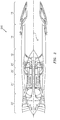
- FIG. 1 schematically illustrates a gas turbine engine 20.
- the gas turbine engine 20 is disclosed herein as a two-spool turbo fan that generally incorporates a fan section 22, a compressor section 24, a combustor section 26 and a turbine section 28.
- another alternative engine architecture 200 might include an augmentor section 12, an exhaust duct section 14 and a nozzle section 16 in addition to the fan section 22', compressor section 24', combustor section 26' and turbine section 28'.
- the fan section 22 drives air along a bypass flowpath and into the compressor section 24.
- the compressor section 24 drives air along a core flowpath for compression and communication into the combustor section 26, which then expands and directs the air through the turbine section 28.
- the engine 20 generally includes a low spool 30 and a high spool 32 mounted for rotation about an engine central longitudinal axis A relative to an engine static structure 36 via several bearing structures 38.
- the low spool 30 generally includes an inner shaft 40 that interconnects a fan 42, a low pressure compressor (“LPC”) 44 and a low pressure turbine (“LPT”) 46.
- the inner shaft 40 drives the fan 42 directly or through a geared architecture 48 to drive the fan 42 at a lower speed than the low spool 30.
- An exemplary reduction transmission is an epicyclic transmission, namely a planetary or star gear system.
- the high spool 32 includes an outer shaft 50 that interconnects a high pressure compressor (“HPC”) 52 and a high pressure turbine (“HPT”) 54.
- a combustor 56 is arranged between the HPC 52 and the HPT 54.
- the inner shaft 40 and the outer shaft 50 are concentric and rotate about the engine central longitudinal axis A which is collinear with their longitudinal axes.
- Core airflow is compressed by the LPC 44 then the HPC 52, mixed with the fuel and burned in the combustor 56, then expanded over the HPT 54 and the LPT 46.
- the LPT 46 and HPT 54 rotationally drive the respective low spool 30 and high spool 32 in response to the expansion.
- the gas turbine engine 20 is a high-bypass geared aircraft engine with a bypass ratio greater than about six (6:1).
- the geared architecture 48 can include an epicyclic gear train, such as a planetary gear system or other gear system.
- the example epicyclic gear train has a gear reduction ratio of greater than about 2.3:1, and in another example, is greater than about 2.5:1.
- the geared turbofan enables operation of the low spool 30 at higher speeds which can increase the operational efficiency of the LPC 44 and LPT 46 to render increased pressure in a fewer number of stages.
- a pressure ratio associated with the LPT 46 is pressure measured prior to the inlet of the LPT 46 as related to the pressure at the outlet of the LPT 46 prior to an exhaust nozzle of the gas turbine engine 20.
- the bypass ratio of the gas turbine engine 20 is greater than about ten (10:1)
- the fan diameter is significantly larger than that of the LPC 44
- the LPT 46 has a pressure ratio greater than about five (5:1). It should be appreciated, however, that the above parameters are only exemplary of a geared architecture engine and that the present disclosure is applicable to other gas turbine engines including direct drive turbofans.
- TSFC Thrust Specific Fuel Consumption
- Fan Pressure Ratio is the pressure ratio across a fan blade of the fan section 22 without the use of a Fan Exit Guide Vane system.
- the low Fan Pressure Ratio according to one example gas turbine engine 20 is less than 1.45.
- Low Corrected Fan Tip Speed is the actual fan tip speed divided by an industry standard temperature correction of ("Tram" / 518.7) 0.5 .
- the Low Corrected Fan Tip Speed according to the example gas turbine engine 20 is less than about 1150 fps (351 m/s).
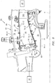
- the combustor section 26 generally includes a combustor 56 with an outer combustor wall assembly 60, an inner combustor wall assembly 62 and a diffuser case module 64.
- the outer combustor wall assembly 60 and the inner combustor wall assembly 62 are spaced apart such that an annular combustion chamber 66 is defined therebetween.
- the outer combustor wall assembly 60 is spaced radially inward from an outer diffuser case 64-0 of the diffuser case module 64 to define an outer annular plenum 76.
- the inner combustor wall assembly 62 is spaced radially outward from an inner diffuser case 64-1 of the diffuser case module 64 to define an inner annular plenum 78. It should be understood that although a particular combustor is illustrated, other combustor types with various combustor wall and diffuser case module arrangements will also benefit herefrom.
- the combustor wall assemblies 60, 62 contain the combustion products for direction toward the turbine section 28.
- Each combustor wall assembly 60, 62 generally includes a respective support shell 68, 70 which supports one or more liner panels 72, 74 mounted within the respective support shell 68, 70.
- Each of the liner panels 72, 74 may be generally rectilinear with a circumferential arc and manufactured of, for example, a nickel based super alloy, ceramic or other temperature resistant material and are arranged to form a liner array.
- the liner array includes a multiple of forward liner panels 72-1 and a multiple of aft liner panels 72-2 that are circumferentially staggered to line the outer shell 68.
- a multiple of forward liner panels 74-1 and a multiple of aft liner panels 74-2 are circumferentially staggered to line the inner shell 70.
- the combustor 56 further includes a forward assembly 80 immediately downstream of the compressor section 24 to receive compressed airflow therefrom.
- the forward assembly 80 generally includes an annular hood 82 and a bulkhead assembly 84 that support a multiple of fuel nozzles 86 (one shown) and a multiple of swirlers 90 (one shown).
- the annular hood 82 extends radially between, and is secured to, the forwardmost ends of the combustor wall assemblies 60, 62.
- the annular hood 82 includes a multiple of circumferentially distributed hood ports 94 each of which accommodates the respective fuel nozzle 86 and introduce air into the forward end of the combustion chamber 66 through a respective swirler 90.
- the bulkhead assembly 84 includes a bulkhead support shell 96 secured to the combustor wall assemblies 60, 62, and a multiple of circumferentially distributed bulkhead liner panels 98 secured to the bulkhead support shell 96.
- Each fuel nozzle 86 may be secured to the diffuser case module 64 and project through one of the hood ports 94 and respective swirlers 90.
- the forward assembly 80 introduces core combustion air into the forward section of the combustion chamber 66 while the remainder enters the outer annular plenum 76 and the inner annular plenum 78.
- the multiple of fuel nozzles 86 and adjacent structure generate a fuel-air mixture that supports stable combustion in the combustion chamber 66.
- the outer and inner support shells 68, 70 are mounted to a first row of Nozzle Guide Vanes (NGVs) 54A in the HPT 54.
- NGVs 54A are static engine components which direct core airflow combustion gases onto turbine blades in the turbine section 28 to facilitate the conversion of pressure energy into kinetic energy.
- the core airflow combustion gases are also accelerated by the NGVs 54A because of their convergent shape and are typically given a "spin” or a "swirl” in the direction of turbine rotor rotation.
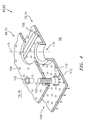
- a multiple of studs 100 extend from the liner panels 72, 74 so as to permit the liner panels 72, 74 to be mounted to their respective support shells 68, 70 with fasteners 102 such as nuts. That is, the studs 100 project rigidly from the liner panels 72, 74 through the respective support shells 68, 70 to receive the fasteners 102 at a threaded distal end section thereof to define one or more impingement cavities 106.
- the liner panels 72, 74 typically include one or more rails 120 (see FIG. 5 ) which extend from a cold side 110 thereof.
- the rail 120 typically extends at least around the periphery of the cold side 110 ( FIG. 5 ) to interface with their respective support shells 68, 70 when mounted thereto to define one or more impingement cavities 106. That is, the rails 120 at least extend around the cold side 110 periphery and may include further internal rails to define additional compartments.
- a multiple of cooling impingement passages 104 penetrate through the support shells 68, 70 to allow air from the respective annular plenums 76, 78 to enter impingement cavities 106 formed within the combustor wall assemblies 60, 62 between the respective support shells 68, 70 and liner panels 72, 74.
- the cooling impingement passages 104 are generally normal to the surface of the liner panels 72, 74.
- the air in the impingement cavities 106 provides cold side impingement cooling of the liner panels 72, 74 that is generally defined herein as heat removal via internal convection.
- a multiple of effusion passages 108 penetrate through each of the liner panels 72, 74.
- the geometry of the passages e.g., diameter, shape, density, surface angle, incidence angle, etc.
- the combination of impingement passages 104 and effusion passages 108 for a double wall architecture may be referred to as an Impingement Film Floatwall (IFF) assembly.
- IFF Impingement Film Floatwall
- the effusion passages 108 allow air to pass from each impingement cavity 106 defined in part by the cold side 110 of the liner panels 72, 74 to a hot side 112 thereof to facilitate the formation of a relatively thin, insulating blanket of cooling air along the hot side 112.
- the effusion passages 108 are generally more numerous than the impingement passages 104 to promote the development of a sheath of film cooling along the hot side 112.
- Film cooling as defined herein is the introduction of a relatively cooler air at one or more discrete locations along a surface exposed to a high temperature environment to protect that surface in the region of the air injection as well as downstream thereof.
- Each of the multiple of dilution passages 116 may also penetrate through the respective support shells 68, 70 and liner panels 72, 74 along a common axis D.
- the dilution passages 116 are axially located to dilute the hot combustion gases within the combustion chamber 66 by direct supply of cooling air from the respective annular plenums 76, 78.
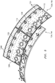
- the multiple rails 120 define two (2) impingement cavities 106A, 106B in this example liner panel 72. It should be appreciated that although two (2) impingement cavities 106A, 106B are illustrated for descriptive purposes in one outer liner panel 72, any number and arrangement of impingement cavities 106 (four shown in FIG. 6 ) will benefit herefrom as well as the inner liner panel 74. It should be appreciated that, although only an example outer liner panel 72 is illustrated in the disclosed non-limiting embodiment, the inner liner panels 74 will also benefit herefrom.
- each impingement cavity 106A, 106B is configured to operate at a different pressure, and thereby defines different controlled pressure drops. That is, impingement cavity 106A operates at a first pressure while impingement cavity 106B operates at a second pressure different than the first pressure.
- Such differential pressure within a single liner panel 72, 74 facilitates, for example, tailored cooling effects for different circumferential and/or axial conditions within the combustion chamber 66.
- the pressure drop across the combustor 56 may be defined as an impingement pressure drop across the support shell 68, 70 and an effusion pressure drop across the liner panels 72, 74 for each impingement cavity 106A, 106B.
- the impingement cavity 106A may define an about 80% impingement pressure drop for impingement flow and about 20% for effusion flow while impingement cavity 106B may provide a 70%-30% split. It should be appreciated that various pressure drop splits may be defined for each impingement cavity 106A, 106B.
- the differential pressure within the impingement cavities 106A, 106B is provided by multiple impingement passages 104 of different diameters for each respective impingement cavity 106A, 106B.
- each impingement passage 104A which communicates with impingement cavity 106A defines a first diameter while each impingement passage 104B which communicates with impingement cavity 106B defines a second diameter different than the first diameter.
- the impingement passages 104A, 104B are laser drilled and thereby readily manufactured and associated with the specific impingement cavity 106A, 106B.
- the differential pressure within the impingement cavities 106A, 106B is obtained by differing ratios of impingement passages 104 (which may or may not be of the same diameter) to effusion passages 108 for the respective impingement cavity 106A, 106B to provide the desired differential pressures within the respective impingement cavities 106A, 106B.
- the differential pressure within the impingement cavities 106A, 106B is provided by a reduced height rail 120A.
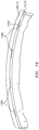
- the reduced height rail 120A does not contact the respective support shell 68 and forms an effusion slot 108A between the liner panel 72 and support shell 68 at a trailing edge 140 of each or either of the wall assemblies 60, 62 ( FIG. 10 ).
- the effusion slot 140 is open to the impingement cavity 106B, and thereby varies the pressure drop thereof as the slot 140 operates as an additional effusion passage.
- the reduced height rail 120A may extend circumferentially for only discrete lengths to define circumferential slots 108A ( FIG. 10 ).
- annular impingement cavity 106C may additionally be formed by an annular grommet 150 mounted between the respective support shell 68, 70 and associated liner panels 72, 74.
- the annular grommet 150 permits the respective support shell 68, 70 and associated liner panels 72, 74 to be manufactured as generally consistent flat panels as the annular grommet 150 separately defines the dilution passage 116.
- the impingement cavity 106C is generally annular and defined between the annular grommet 150 and the respective support shell 68, 70. That is, the interface geometry between the annular grommet 150 and the respective support shell 68, 70 defines a generally annular impingement passage 104C.
- the annular grommet 150 abuts the respective liner panel 72, 74 and includes one or more effusion passages 108C therethrough.
- the effusion passages 108C facilitate a relatively high pressure drop as the annular impingement cavity 106C is open to the respective annular plenum 76, 78. It should be appreciated that other geometries may be provided to facilitate formation of the differential pressures and desired controlled pressure drops.
- Controlled pressure drop across the supports shells and respective liner panels facilitates tailored cooling effectiveness for the different boundary conditions of the liner panel hot face. For example, increased pressure drop through the effusion holes provides a greater lifting effect on the hot combustion gases to enhance durability of the liner panels where impinging combustion products pose a potential risk of backflow while reduced pressure drop through the effusion holes is desirable to provide a relatively low velocity flow that remains attached to the hot side of the liner panel.
Claims (13)
- Brennkammer (56) eines Gasturbinentriebwerks (20), umfassend:einen Stützmantel (68, 70), der eine Mehrzahl von Prallströmungskanälen (104) definiert; undeine Mehrzahl von Auskleidungsplatten (72, 74), die an dem Stützmantel (68, 70) montiert sind, wobei wenigstens eine der Mehrzahl von Auskleidungsplatten (72, 74) einen ersten Prallströmungshohlraum (106A) mit dem Stützmantel (68, 70) und einen zweiten Prallströmungshohlraum (106B) mit dem Stützmantel definiert;eine erste Mehrzahl von Effusionsströmungskanälen (108) durch die wenigstens eine der Mehrzahl von Auskleidungsplatten (72, 74) und in Kommunikation mit dem ersten Prallströmungshohlraum (106A); undeine zweite Mehrzahl von Effusionsströmungskanälen (108) durch die wenigstens eine der Mehrzahl von Auskleidungsplatten (72, 74) und in Kommunikation mit dem zweiten Prallströmungshohlraum (106B);wobei der Stützmantel (68, 70) eine erste Mehrzahl von Prallströmungskanälen (104A), die in dem Stützmantel (68, 70) definiert sind und in Kommunikation mit dem ersten Prallströmungskanal (106A) stehen, und eine zweite Mehrzahl von Prallströmungskanälen (104B), die in dem Stützmantel (68, 70) definiert sind und in Kommunikation mit dem zweiten Prallströmungskanal (106B) stehen, definiert;wobei die erste Mehrzahl von Prallströmungskanälen (104A) und die erste Mehrzahl von Effusionsströmungskanälen (108) ein erstes Verhältnis definieren und die zweite Mehrzahl von Prallströmungskanälen (104B) und die zweite Mehrzahl von Effusionsströmungskanälen (108) ein zweites Verhältnis definieren, wobei das erste Verhältnis sich derart von dem zweiten Verhältnis unterscheidet, dass der erste Prallströmungshohlraum (106A) bei einem ersten Druck betrieben werden kann und der zweite Prallströmungshohlraum (106B) bei einem zweiten Druck betrieben werden kann, der sich von dem ersten Druck unterscheidet.
- Brennkammer nach Anspruch 1, wobei eines von dem Stützmantel (68, 70) und der Mehrzahl von Auskleidungsplatten (72, 74) eine Schiene (120) beinhaltet, die ausgelegt ist, den ersten Prallströmungshohlraum (106A) und den zweiten Prallströmungshohlraum (106B) zu trennen.
- Brennkammer nach Anspruch 2, ferner umfassend eine Schiene mit verringerter Höhe (120A), die benachbart zu dem Stützmantel (68, 70) liegt.
- Brennkammer nach Anspruch 3, wobei die Schiene mit verringerter Höhe (120A) eine Hinterkante (140) der wenigstens einen von der Mehrzahl von Auskleidungsplatten (72, 74) definiert.
- Brennkammer nach einem der vorhergehenden Ansprüche, wobei:wenigstens eine von der ersten Mehrzahl von Prallströmungskanälen (104A) einen Durchmesser definiert, der sich wenigstens von einem von der zweiten Mehrzahl von Prallströmungskanälen (104B) unterscheidet;jeder von der ersten Mehrzahl von Prallströmungskanälen (104A) einen Durchmesser definiert, der sich von jedem von der zweiten Mehrzahl von Prallströmungskanälen (104B) unterscheidet.
- Brennkammer nach einem der vorhergehenden Ansprüche, wobei die erste Mehrzahl von Prallströmungskanälen (104A) zahlreicher ist als die zweite Mehrzahl von Prallströmungskanälen (104B).
- Brennkammer nach einem der vorhergehenden Ansprüche, ferner umfassend eine ringförmige Durchführung (150) zwischen dem Stützmantel (68, 70) und der wenigstens einen von der Mehrzahl von Auskleidungsplatten (72, 74), wobei die ringförmige Durchführung (150) und der Stützmantel (68, 70) einen ringförmigen Prallströmungshohlraum (106C) definieren, und wenigstens einen Effusionsströmungskanal (108) durch die ringförmige Durchführung (150) und die wenigstens eine von der Mehrzahl von Auskleidungsplatten (68, 70).
- Brennkammer nach Anspruch 1, wobei die Mehrzahl von Auskleidungsplatten (68, 70) eine erste Auskleidungsplatte, die den ersten Prallströmungshohlraum (106A) beinhaltet, und eine zweite Auskleidungsplatte, die den zweiten Prallströmungshohlraum (106B) beinhaltet, beinhaltet, wobei die Brennkammer (56) ferner eine Vielzahl von Stiftschrauben (100) umfasst, die sich von einer kalten Seite jeder der Mehrzahl von Auskleidungsplatten erstrecken, wobei sich die Stiftschrauben (100) durch den Stützmantel erstrecken.
- Brennkammer nach Anspruch 8, ferner umfassend:eine erste Schiene (120) um einen Umfang der ersten Auskleidungsplatte; undeine zweite Schiene (120) um einen Umfang der zweiten Auskleidungsplatte;wobei die erste Schiene und die zweite Schiene in Kontakt mit dem Stützmantel (68, 70) stehen, um die erste Auskleidungsplatte und die zweite Auskleidungsplatte zu trennen.
- Verfahren zum Kühlen einer Wandbaugruppe in einer Brennkammer (56) eines Gasturbinentriebwerks (20), umfassend:das Definieren einer ersten Mehrzahl von Effusionsströmungskanälen (108) durch wenigstens eine von der Mehrzahl von Auskleidungsplatten (72, 74) und in Kommunikation mit einem ersten Prallströmungshohlraum (106A),und das Definieren einer zweiten Mehrzahl von Effusionsströmungskanälen (108) durch die wenigstens eine von der Mehrzahl von Auskleidungsplatten (72, 74) und in Kommunikation mit einem zweiten Prallströmungshohlraum (106B);das Definieren einer ersten Mehrzahl von Prallströmungskanälen (104A) in einem Stützmantel (68, 70) und in Kommunikation mit dem ersten Prallströmungshohlraum (106A) und einer zweiten Mehrzahl von Prallströmungskanälen (104B) in dem Stützmantel (68, 70) und in Kommunikation mit dem zweiten Prallströmungshohlraum (106B); wobeidie erste Mehrzahl von Prallströmungskanälen (104A) und die erste Mehrzahl von Effusionsströmungskanälen (108) ein erstes Verhältnis definieren und die zweite Mehrzahl von Prallströmungskanälen (104B) und die zweite Mehrzahl von Effusionsströmungskanälen (108) ein zweites Verhältnis definieren, wobei das erste Verhältnis sich derart von dem zweiten Verhältnis unterscheidet, dass der erste Prallströmungshohlraum (106A) bei einem ersten Druck betrieben wird und der zweite Prallströmungshohlraum (106B) bei einem zweiten Druck betrieben wird, der sich von dem ersten Druck unterscheidet.
- Verfahren nach Anspruch 10, ferner umfassend das Leiten von Luft aus dem zweiten Prallströmungshohlraum (106B) durch eine Hinterkante (140) der wenigstens einen von den Auskleidungsplatten (72, 74), die an dem Stützmantel (68, 70) montiert sind, oder das Leiten von Luft von einem ringförmigen Prallströmungshohlraum (106C), der wenigstens teilweise durch eine ringförmigen Durchführung (150) zwischen dem Stützmantel (68, 70) und der wenigstens einen von den Auskleidungsplatten (72, 74) definiert ist.
- Verfahren nach Anspruch 10 oder 11, ferner umfassend das Bilden eines ersten Prallströmungsdruckabfalls an dem Stützmantel (68, 70) in dem ersten Prallströmungshohlraum (106A) und eines zweiten Prallströmungsdruckabfalls an dem Stützmantel (68, 70) in dem zweiten Prallströmungshohlraum (106B), wobei sich der erste Prallströmungsdruckabfall von dem zweiten Prallströmungsdruckabfall unterscheidet.
- Verfahren nach Anspruch 10, 11 oder 12, ferner umfassend das Bilden eines ersten Effusionsdruckabfalls an der wenigstens einen von den Auskleidungsplatten (72, 74) in Bezug auf den ersten Prallströmungshohlraum (106A) und eines zweiten Effusionsdruckabfalls an der wenigstens einen von den Auskleidungsplatten (72, 74) in Bezug auf den zweiten Prallströmungshohlraum (106B), wobei sich der erste Effusionsströmungsdruckabfall von dem zweiten Effusionsströmungsdruckabfall unterscheidet.
Applications Claiming Priority (2)
| Application Number | Priority Date | Filing Date | Title |
|---|---|---|---|
| US201361878327P | 2013-09-16 | 2013-09-16 | |
| PCT/US2014/055784 WO2015039074A1 (en) | 2013-09-16 | 2014-09-16 | Controlled variation of pressure drop through effusion cooling in a double walled combustor of a gas turbine engine |
Publications (3)
| Publication Number | Publication Date |
|---|---|
| EP3047128A1 EP3047128A1 (de) | 2016-07-27 |
| EP3047128A4 EP3047128A4 (de) | 2016-08-24 |
| EP3047128B1 true EP3047128B1 (de) | 2018-10-31 |
Family
ID=52666406
Family Applications (1)
| Application Number | Title | Priority Date | Filing Date |
|---|---|---|---|
| EP14844554.7A Active EP3047128B1 (de) | 2013-09-16 | 2014-09-16 | Kontrollierte variation des druckabfalls durch effusionskühlung in einer doppelwandigen brennkammer eines gasturbinentriebwerks |
Country Status (3)
| Country | Link |
|---|---|
| US (1) | US10731858B2 (de) |
| EP (1) | EP3047128B1 (de) |
| WO (1) | WO2015039074A1 (de) |
Families Citing this family (10)
| Publication number | Priority date | Publication date | Assignee | Title |
|---|---|---|---|---|
| GB201418042D0 (en) * | 2014-10-13 | 2014-11-26 | Rolls Royce Plc | A liner element for a combustor, and a related method |
| US9803863B2 (en) * | 2015-05-13 | 2017-10-31 | Solar Turbines Incorporated | Controlled-leak combustor grommet |
| GB201518345D0 (en) | 2015-10-16 | 2015-12-02 | Rolls Royce | Combustor for a gas turbine engine |
| GB201613208D0 (en) * | 2016-08-01 | 2016-09-14 | Rolls Royce Plc | A combustion chamber assembly and a combustion chamber segment |
| US11143401B2 (en) | 2017-12-22 | 2021-10-12 | Raytheon Technologies Corporation | Apparatus and method for mitigating particulate accumulation on a component of a gas turbine |
| US11486578B2 (en) | 2020-05-26 | 2022-11-01 | Raytheon Technologies Corporation | Multi-walled structure for a gas turbine engine |
| US11371701B1 (en) | 2021-02-03 | 2022-06-28 | General Electric Company | Combustor for a gas turbine engine |
| US11959643B2 (en) | 2021-06-07 | 2024-04-16 | General Electric Company | Combustor for a gas turbine engine |
| US11885495B2 (en) | 2021-06-07 | 2024-01-30 | General Electric Company | Combustor for a gas turbine engine including a liner having a looped feature |
| US11774098B2 (en) | 2021-06-07 | 2023-10-03 | General Electric Company | Combustor for a gas turbine engine |
Family Cites Families (36)
| Publication number | Priority date | Publication date | Assignee | Title |
|---|---|---|---|---|
| US553864A (en) * | 1896-02-04 | Running-gear for vehicles | ||
| US4132066A (en) * | 1977-09-23 | 1979-01-02 | United Technologies Corporation | Combustor liner for gas turbine engine |
| US4653279A (en) * | 1985-01-07 | 1987-03-31 | United Technologies Corporation | Integral refilmer lip for floatwall panels |
| US5331816A (en) * | 1992-10-13 | 1994-07-26 | United Technologies Corporation | Gas turbine engine combustor fiber reinforced glass ceramic matrix liner with embedded refractory ceramic tiles |
| JP3110227B2 (ja) * | 1993-11-22 | 2000-11-20 | 株式会社東芝 | タービン冷却翼 |
| US6205789B1 (en) | 1998-11-13 | 2001-03-27 | General Electric Company | Multi-hole film cooled combuster liner |
| GB9926257D0 (en) | 1999-11-06 | 2000-01-12 | Rolls Royce Plc | Wall elements for gas turbine engine combustors |
| GB2361303B (en) | 2000-04-14 | 2004-10-20 | Rolls Royce Plc | Wall structure for a gas turbine engine combustor |
| US6606861B2 (en) | 2001-02-26 | 2003-08-19 | United Technologies Corporation | Low emissions combustor for a gas turbine engine |
| DE10155420A1 (de) | 2001-11-12 | 2003-05-22 | Rolls Royce Deutschland | Hitzeschildanordnung mit Dichtungselement |
| DE10214570A1 (de) | 2002-04-02 | 2004-01-15 | Rolls-Royce Deutschland Ltd & Co Kg | Mischluftloch in Gasturbinenbrennkammer mit Brennkammerschindeln |
| US7086232B2 (en) | 2002-04-29 | 2006-08-08 | General Electric Company | Multihole patch for combustor liner of a gas turbine engine |
| GB0305025D0 (en) | 2003-03-05 | 2003-04-09 | Alstom Switzerland Ltd | Method and device for efficient usage of cooling air for acoustic damping of combustion chamber pulsations |
| US6964170B2 (en) | 2003-04-28 | 2005-11-15 | Pratt & Whitney Canada Corp. | Noise reducing combustor |
| US7146815B2 (en) | 2003-07-31 | 2006-12-12 | United Technologies Corporation | Combustor |
| EP1507116A1 (de) | 2003-08-13 | 2005-02-16 | Siemens Aktiengesellschaft | Hitzeschildanordnung für eine ein Heissgas führende Komponente, insbesondere für eine Brennkammer einer Gasturbine |
| US7093441B2 (en) | 2003-10-09 | 2006-08-22 | United Technologies Corporation | Gas turbine annular combustor having a first converging volume and a second converging volume, converging less gradually than the first converging volume |
| US7363763B2 (en) | 2003-10-23 | 2008-04-29 | United Technologies Corporation | Combustor |
| US7018176B2 (en) * | 2004-05-06 | 2006-03-28 | United Technologies Corporation | Cooled turbine airfoil |
| US7464554B2 (en) | 2004-09-09 | 2008-12-16 | United Technologies Corporation | Gas turbine combustor heat shield panel or exhaust panel including a cooling device |
| US7954325B2 (en) | 2005-12-06 | 2011-06-07 | United Technologies Corporation | Gas turbine combustor |
| GB2453946B (en) | 2007-10-23 | 2010-07-14 | Rolls Royce Plc | A Wall Element for use in Combustion Apparatus |
| GB0801839D0 (en) | 2008-02-01 | 2008-03-05 | Rolls Royce Plc | combustion apparatus |
| US20100095680A1 (en) | 2008-10-22 | 2010-04-22 | Honeywell International Inc. | Dual wall structure for use in a combustor of a gas turbine engine |
| US20100095679A1 (en) | 2008-10-22 | 2010-04-22 | Honeywell International Inc. | Dual wall structure for use in a combustor of a gas turbine engine |
| US8348613B2 (en) * | 2009-03-30 | 2013-01-08 | United Technologies Corporation | Airflow influencing airfoil feature array |
| JP5291799B2 (ja) * | 2009-08-24 | 2013-09-18 | 三菱重工業株式会社 | 分割環冷却構造およびガスタービン |
| US20110185739A1 (en) | 2010-01-29 | 2011-08-04 | Honeywell International Inc. | Gas turbine combustors with dual walled liners |
| EP2463582B1 (de) * | 2010-12-10 | 2019-06-19 | Rolls-Royce plc | Brennkammer |
| JP5696566B2 (ja) | 2011-03-31 | 2015-04-08 | 株式会社Ihi | ガスタービンエンジン用燃焼器及びガスタービンエンジン |
| US9222674B2 (en) | 2011-07-21 | 2015-12-29 | United Technologies Corporation | Multi-stage amplification vortex mixture for gas turbine engine combustor |
| US8978385B2 (en) * | 2011-07-29 | 2015-03-17 | United Technologies Corporation | Distributed cooling for gas turbine engine combustor |
| JP5821550B2 (ja) | 2011-11-10 | 2015-11-24 | 株式会社Ihi | 燃焼器ライナ |
| US20130298564A1 (en) * | 2012-05-14 | 2013-11-14 | General Electric Company | Cooling system and method for turbine system |
| US9052111B2 (en) | 2012-06-22 | 2015-06-09 | United Technologies Corporation | Turbine engine combustor wall with non-uniform distribution of effusion apertures |
| WO2014052966A1 (en) | 2012-09-28 | 2014-04-03 | United Technologies Corporation | Combustor section of a gas turbine engine |
-
2014
- 2014-09-16 EP EP14844554.7A patent/EP3047128B1/de active Active
- 2014-09-16 US US14/913,795 patent/US10731858B2/en active Active
- 2014-09-16 WO PCT/US2014/055784 patent/WO2015039074A1/en active Application Filing
Non-Patent Citations (1)
| Title |
|---|
| None * |
Also Published As
| Publication number | Publication date |
|---|---|
| US10731858B2 (en) | 2020-08-04 |
| US20160356500A1 (en) | 2016-12-08 |
| WO2015039074A1 (en) | 2015-03-19 |
| EP3047128A4 (de) | 2016-08-24 |
| EP3047128A1 (de) | 2016-07-27 |
Similar Documents
| Publication | Publication Date | Title |
|---|---|---|
| EP3047128B1 (de) | Kontrollierte variation des druckabfalls durch effusionskühlung in einer doppelwandigen brennkammer eines gasturbinentriebwerks | |
| EP2959136B1 (de) | Brennkammer eines gasturbinenmotors mit gerippter zünderdichtung | |
| US20160123592A1 (en) | Gas turbine engine combustor liner panel | |
| EP3077728B1 (de) | Gasturbinenbrennkammer mit co-swirl-ausrichtung von effusionslöchern, und methode | |
| US10488046B2 (en) | Gas turbine engine combustor bulkhead assembly | |
| EP3008386B1 (de) | Innenverkleidungstafel für einen gasturbinenmotor | |
| EP2932070B1 (de) | Gasturbinenbrennkammer-hitzeschild mit erhöhter filmkühlwirksamkeit | |
| US20160186998A1 (en) | Contoured dilution passages for gas turbine engine combustor | |
| US10816201B2 (en) | Sealed combustor liner panel for a gas turbine engine | |
| US20160201908A1 (en) | Vena contracta swirling dilution passages for gas turbine engine combustor | |
| US10508808B2 (en) | Gas turbine engine wave geometry combustor liner panel | |
| EP3315730A1 (de) | Brennkammerdichtung für eine gasturbinenbrennkammer | |
| US20160334103A1 (en) | Dilution passage arrangement for gas turbine engine combustor | |
| EP3315862B1 (de) | Gegossene brennkammerauskleidungsplatte mit radiuskante für gasturbinenbrennkammer |
Legal Events
| Date | Code | Title | Description |
|---|---|---|---|
| PUAI | Public reference made under article 153(3) epc to a published international application that has entered the european phase |
Free format text: ORIGINAL CODE: 0009012 |
|
| 17P | Request for examination filed |
Effective date: 20160418 |
|
| AK | Designated contracting states |
Kind code of ref document: A1 Designated state(s): AL AT BE BG CH CY CZ DE DK EE ES FI FR GB GR HR HU IE IS IT LI LT LU LV MC MK MT NL NO PL PT RO RS SE SI SK SM TR |
|
| AX | Request for extension of the european patent |
Extension state: BA ME |
|
| A4 | Supplementary search report drawn up and despatched |
Effective date: 20160726 |
|
| RIC1 | Information provided on ipc code assigned before grant |
Ipc: F23R 3/04 20060101ALI20160720BHEP Ipc: F02C 7/12 20060101AFI20160720BHEP Ipc: F23R 3/06 20060101ALI20160720BHEP Ipc: F02C 7/24 20060101ALI20160720BHEP Ipc: F23M 5/04 20060101ALI20160720BHEP Ipc: F23R 3/42 20060101ALI20160720BHEP |
|
| RAP1 | Party data changed (applicant data changed or rights of an application transferred) |
Owner name: UNITED TECHNOLOGIES CORPORATION |
|
| DAX | Request for extension of the european patent (deleted) | ||
| STAA | Information on the status of an ep patent application or granted ep patent |
Free format text: STATUS: REQUEST FOR EXAMINATION WAS MADE |
|
| GRAP | Despatch of communication of intention to grant a patent |
Free format text: ORIGINAL CODE: EPIDOSNIGR1 |
|
| STAA | Information on the status of an ep patent application or granted ep patent |
Free format text: STATUS: GRANT OF PATENT IS INTENDED |
|
| INTG | Intention to grant announced |
Effective date: 20180420 |
|
| GRAS | Grant fee paid |
Free format text: ORIGINAL CODE: EPIDOSNIGR3 |
|
| GRAA | (expected) grant |
Free format text: ORIGINAL CODE: 0009210 |
|
| STAA | Information on the status of an ep patent application or granted ep patent |
Free format text: STATUS: THE PATENT HAS BEEN GRANTED |
|
| AK | Designated contracting states |
Kind code of ref document: B1 Designated state(s): AL AT BE BG CH CY CZ DE DK EE ES FI FR GB GR HR HU IE IS IT LI LT LU LV MC MK MT NL NO PL PT RO RS SE SI SK SM TR |
|
| REG | Reference to a national code |
Ref country code: CH Ref legal event code: EP Ref country code: GB Ref legal event code: FG4D |
|
| REG | Reference to a national code |
Ref country code: AT Ref legal event code: REF Ref document number: 1059694 Country of ref document: AT Kind code of ref document: T Effective date: 20181115 |
|
| REG | Reference to a national code |
Ref country code: IE Ref legal event code: FG4D |
|
| REG | Reference to a national code |
Ref country code: DE Ref legal event code: R096 Ref document number: 602014035309 Country of ref document: DE |
|
| REG | Reference to a national code |
Ref country code: NL Ref legal event code: MP Effective date: 20181031 |
|
| REG | Reference to a national code |
Ref country code: LT Ref legal event code: MG4D |
|
| REG | Reference to a national code |
Ref country code: AT Ref legal event code: MK05 Ref document number: 1059694 Country of ref document: AT Kind code of ref document: T Effective date: 20181031 |
|
| PG25 | Lapsed in a contracting state [announced via postgrant information from national office to epo] |
Ref country code: FI Free format text: LAPSE BECAUSE OF FAILURE TO SUBMIT A TRANSLATION OF THE DESCRIPTION OR TO PAY THE FEE WITHIN THE PRESCRIBED TIME-LIMIT Effective date: 20181031 Ref country code: BG Free format text: LAPSE BECAUSE OF FAILURE TO SUBMIT A TRANSLATION OF THE DESCRIPTION OR TO PAY THE FEE WITHIN THE PRESCRIBED TIME-LIMIT Effective date: 20190131 Ref country code: PL Free format text: LAPSE BECAUSE OF FAILURE TO SUBMIT A TRANSLATION OF THE DESCRIPTION OR TO PAY THE FEE WITHIN THE PRESCRIBED TIME-LIMIT Effective date: 20181031 Ref country code: HR Free format text: LAPSE BECAUSE OF FAILURE TO SUBMIT A TRANSLATION OF THE DESCRIPTION OR TO PAY THE FEE WITHIN THE PRESCRIBED TIME-LIMIT Effective date: 20181031 Ref country code: LV Free format text: LAPSE BECAUSE OF FAILURE TO SUBMIT A TRANSLATION OF THE DESCRIPTION OR TO PAY THE FEE WITHIN THE PRESCRIBED TIME-LIMIT Effective date: 20181031 Ref country code: AT Free format text: LAPSE BECAUSE OF FAILURE TO SUBMIT A TRANSLATION OF THE DESCRIPTION OR TO PAY THE FEE WITHIN THE PRESCRIBED TIME-LIMIT Effective date: 20181031 Ref country code: IS Free format text: LAPSE BECAUSE OF FAILURE TO SUBMIT A TRANSLATION OF THE DESCRIPTION OR TO PAY THE FEE WITHIN THE PRESCRIBED TIME-LIMIT Effective date: 20190228 Ref country code: ES Free format text: LAPSE BECAUSE OF FAILURE TO SUBMIT A TRANSLATION OF THE DESCRIPTION OR TO PAY THE FEE WITHIN THE PRESCRIBED TIME-LIMIT Effective date: 20181031 Ref country code: LT Free format text: LAPSE BECAUSE OF FAILURE TO SUBMIT A TRANSLATION OF THE DESCRIPTION OR TO PAY THE FEE WITHIN THE PRESCRIBED TIME-LIMIT Effective date: 20181031 Ref country code: NO Free format text: LAPSE BECAUSE OF FAILURE TO SUBMIT A TRANSLATION OF THE DESCRIPTION OR TO PAY THE FEE WITHIN THE PRESCRIBED TIME-LIMIT Effective date: 20190131 |
|
| PG25 | Lapsed in a contracting state [announced via postgrant information from national office to epo] |
Ref country code: AL Free format text: LAPSE BECAUSE OF FAILURE TO SUBMIT A TRANSLATION OF THE DESCRIPTION OR TO PAY THE FEE WITHIN THE PRESCRIBED TIME-LIMIT Effective date: 20181031 Ref country code: NL Free format text: LAPSE BECAUSE OF FAILURE TO SUBMIT A TRANSLATION OF THE DESCRIPTION OR TO PAY THE FEE WITHIN THE PRESCRIBED TIME-LIMIT Effective date: 20181031 Ref country code: PT Free format text: LAPSE BECAUSE OF FAILURE TO SUBMIT A TRANSLATION OF THE DESCRIPTION OR TO PAY THE FEE WITHIN THE PRESCRIBED TIME-LIMIT Effective date: 20190301 Ref country code: RS Free format text: LAPSE BECAUSE OF FAILURE TO SUBMIT A TRANSLATION OF THE DESCRIPTION OR TO PAY THE FEE WITHIN THE PRESCRIBED TIME-LIMIT Effective date: 20181031 Ref country code: SE Free format text: LAPSE BECAUSE OF FAILURE TO SUBMIT A TRANSLATION OF THE DESCRIPTION OR TO PAY THE FEE WITHIN THE PRESCRIBED TIME-LIMIT Effective date: 20181031 Ref country code: GR Free format text: LAPSE BECAUSE OF FAILURE TO SUBMIT A TRANSLATION OF THE DESCRIPTION OR TO PAY THE FEE WITHIN THE PRESCRIBED TIME-LIMIT Effective date: 20190201 |
|
| PG25 | Lapsed in a contracting state [announced via postgrant information from national office to epo] |
Ref country code: IT Free format text: LAPSE BECAUSE OF FAILURE TO SUBMIT A TRANSLATION OF THE DESCRIPTION OR TO PAY THE FEE WITHIN THE PRESCRIBED TIME-LIMIT Effective date: 20181031 Ref country code: CZ Free format text: LAPSE BECAUSE OF FAILURE TO SUBMIT A TRANSLATION OF THE DESCRIPTION OR TO PAY THE FEE WITHIN THE PRESCRIBED TIME-LIMIT Effective date: 20181031 Ref country code: DK Free format text: LAPSE BECAUSE OF FAILURE TO SUBMIT A TRANSLATION OF THE DESCRIPTION OR TO PAY THE FEE WITHIN THE PRESCRIBED TIME-LIMIT Effective date: 20181031 |
|
| REG | Reference to a national code |
Ref country code: DE Ref legal event code: R097 Ref document number: 602014035309 Country of ref document: DE |
|
| PG25 | Lapsed in a contracting state [announced via postgrant information from national office to epo] |
Ref country code: EE Free format text: LAPSE BECAUSE OF FAILURE TO SUBMIT A TRANSLATION OF THE DESCRIPTION OR TO PAY THE FEE WITHIN THE PRESCRIBED TIME-LIMIT Effective date: 20181031 Ref country code: SM Free format text: LAPSE BECAUSE OF FAILURE TO SUBMIT A TRANSLATION OF THE DESCRIPTION OR TO PAY THE FEE WITHIN THE PRESCRIBED TIME-LIMIT Effective date: 20181031 Ref country code: SK Free format text: LAPSE BECAUSE OF FAILURE TO SUBMIT A TRANSLATION OF THE DESCRIPTION OR TO PAY THE FEE WITHIN THE PRESCRIBED TIME-LIMIT Effective date: 20181031 Ref country code: RO Free format text: LAPSE BECAUSE OF FAILURE TO SUBMIT A TRANSLATION OF THE DESCRIPTION OR TO PAY THE FEE WITHIN THE PRESCRIBED TIME-LIMIT Effective date: 20181031 |
|
| PLBE | No opposition filed within time limit |
Free format text: ORIGINAL CODE: 0009261 |
|
| STAA | Information on the status of an ep patent application or granted ep patent |
Free format text: STATUS: NO OPPOSITION FILED WITHIN TIME LIMIT |
|
| 26N | No opposition filed |
Effective date: 20190801 |
|
| PG25 | Lapsed in a contracting state [announced via postgrant information from national office to epo] |
Ref country code: SI Free format text: LAPSE BECAUSE OF FAILURE TO SUBMIT A TRANSLATION OF THE DESCRIPTION OR TO PAY THE FEE WITHIN THE PRESCRIBED TIME-LIMIT Effective date: 20181031 |
|
| PG25 | Lapsed in a contracting state [announced via postgrant information from national office to epo] |
Ref country code: TR Free format text: LAPSE BECAUSE OF FAILURE TO SUBMIT A TRANSLATION OF THE DESCRIPTION OR TO PAY THE FEE WITHIN THE PRESCRIBED TIME-LIMIT Effective date: 20181031 |
|
| PG25 | Lapsed in a contracting state [announced via postgrant information from national office to epo] |
Ref country code: MC Free format text: LAPSE BECAUSE OF FAILURE TO SUBMIT A TRANSLATION OF THE DESCRIPTION OR TO PAY THE FEE WITHIN THE PRESCRIBED TIME-LIMIT Effective date: 20181031 |
|
| REG | Reference to a national code |
Ref country code: CH Ref legal event code: PL |
|
| PG25 | Lapsed in a contracting state [announced via postgrant information from national office to epo] |
Ref country code: CH Free format text: LAPSE BECAUSE OF NON-PAYMENT OF DUE FEES Effective date: 20190930 Ref country code: LI Free format text: LAPSE BECAUSE OF NON-PAYMENT OF DUE FEES Effective date: 20190930 Ref country code: IE Free format text: LAPSE BECAUSE OF NON-PAYMENT OF DUE FEES Effective date: 20190916 Ref country code: LU Free format text: LAPSE BECAUSE OF NON-PAYMENT OF DUE FEES Effective date: 20190916 |
|
| REG | Reference to a national code |
Ref country code: BE Ref legal event code: MM Effective date: 20190930 |
|
| PG25 | Lapsed in a contracting state [announced via postgrant information from national office to epo] |
Ref country code: BE Free format text: LAPSE BECAUSE OF NON-PAYMENT OF DUE FEES Effective date: 20190930 |
|
| PG25 | Lapsed in a contracting state [announced via postgrant information from national office to epo] |
Ref country code: CY Free format text: LAPSE BECAUSE OF FAILURE TO SUBMIT A TRANSLATION OF THE DESCRIPTION OR TO PAY THE FEE WITHIN THE PRESCRIBED TIME-LIMIT Effective date: 20181031 |
|
| PG25 | Lapsed in a contracting state [announced via postgrant information from national office to epo] |
Ref country code: HU Free format text: LAPSE BECAUSE OF FAILURE TO SUBMIT A TRANSLATION OF THE DESCRIPTION OR TO PAY THE FEE WITHIN THE PRESCRIBED TIME-LIMIT; INVALID AB INITIO Effective date: 20140916 Ref country code: MT Free format text: LAPSE BECAUSE OF FAILURE TO SUBMIT A TRANSLATION OF THE DESCRIPTION OR TO PAY THE FEE WITHIN THE PRESCRIBED TIME-LIMIT Effective date: 20181031 |
|
| PG25 | Lapsed in a contracting state [announced via postgrant information from national office to epo] |
Ref country code: MK Free format text: LAPSE BECAUSE OF FAILURE TO SUBMIT A TRANSLATION OF THE DESCRIPTION OR TO PAY THE FEE WITHIN THE PRESCRIBED TIME-LIMIT Effective date: 20181031 |
|
| REG | Reference to a national code |
Ref country code: DE Ref legal event code: R081 Ref document number: 602014035309 Country of ref document: DE Owner name: RAYTHEON TECHNOLOGIES CORPORATION (N.D.GES.D.S, US Free format text: FORMER OWNER: UNITED TECHNOLOGIES CORPORATION, EAST HARTFORD, CONN., US |
|
| P01 | Opt-out of the competence of the unified patent court (upc) registered |
Effective date: 20230520 |
|
| PGFP | Annual fee paid to national office [announced via postgrant information from national office to epo] |
Ref country code: GB Payment date: 20230823 Year of fee payment: 10 |
|
| PGFP | Annual fee paid to national office [announced via postgrant information from national office to epo] |
Ref country code: FR Payment date: 20230822 Year of fee payment: 10 Ref country code: DE Payment date: 20230822 Year of fee payment: 10 |