EP3047128B1 - Controlled variation of pressure drop through effusion cooling in a double walled combustor of a gas turbine engine - Google Patents
Controlled variation of pressure drop through effusion cooling in a double walled combustor of a gas turbine engine Download PDFInfo
- Publication number
- EP3047128B1 EP3047128B1 EP14844554.7A EP14844554A EP3047128B1 EP 3047128 B1 EP3047128 B1 EP 3047128B1 EP 14844554 A EP14844554 A EP 14844554A EP 3047128 B1 EP3047128 B1 EP 3047128B1
- Authority
- EP
- European Patent Office
- Prior art keywords
- impingement
- flow passages
- support shell
- combustor
- cavity
- Prior art date
- Legal status (The legal status is an assumption and is not a legal conclusion. Google has not performed a legal analysis and makes no representation as to the accuracy of the status listed.)
- Active
Links
- 238000001816 cooling Methods 0.000 title claims description 17
- 238000004891 communication Methods 0.000 claims description 13
- 238000000034 method Methods 0.000 claims description 9
- 239000007789 gas Substances 0.000 description 18
- 238000002485 combustion reaction Methods 0.000 description 12
- 239000000446 fuel Substances 0.000 description 9
- 239000000567 combustion gas Substances 0.000 description 7
- 238000010790 dilution Methods 0.000 description 7
- 239000012895 dilution Substances 0.000 description 7
- 230000000712 assembly Effects 0.000 description 5
- 238000000429 assembly Methods 0.000 description 5
- PXHVJJICTQNCMI-UHFFFAOYSA-N Nickel Chemical compound [Ni] PXHVJJICTQNCMI-UHFFFAOYSA-N 0.000 description 2
- 230000005540 biological transmission Effects 0.000 description 2
- 230000015572 biosynthetic process Effects 0.000 description 2
- 230000000694 effects Effects 0.000 description 2
- 230000003068 static effect Effects 0.000 description 2
- 239000004215 Carbon black (E152) Substances 0.000 description 1
- 230000004888 barrier function Effects 0.000 description 1
- 239000000919 ceramic Substances 0.000 description 1
- 238000006243 chemical reaction Methods 0.000 description 1
- 230000006835 compression Effects 0.000 description 1
- 238000007906 compression Methods 0.000 description 1
- 238000012937 correction Methods 0.000 description 1
- 238000011161 development Methods 0.000 description 1
- 230000009429 distress Effects 0.000 description 1
- 229930195733 hydrocarbon Natural products 0.000 description 1
- 150000002430 hydrocarbons Chemical class 0.000 description 1
- 238000002347 injection Methods 0.000 description 1
- 239000007924 injection Substances 0.000 description 1
- 239000000463 material Substances 0.000 description 1
- 238000005259 measurement Methods 0.000 description 1
- 239000000203 mixture Substances 0.000 description 1
- 239000003607 modifier Substances 0.000 description 1
- 229910052759 nickel Inorganic materials 0.000 description 1
- 230000005855 radiation Effects 0.000 description 1
- 229910000601 superalloy Inorganic materials 0.000 description 1
- 230000003685 thermal hair damage Effects 0.000 description 1
Images


Classifications
-
- F—MECHANICAL ENGINEERING; LIGHTING; HEATING; WEAPONS; BLASTING
- F23—COMBUSTION APPARATUS; COMBUSTION PROCESSES
- F23R—GENERATING COMBUSTION PRODUCTS OF HIGH PRESSURE OR HIGH VELOCITY, e.g. GAS-TURBINE COMBUSTION CHAMBERS
- F23R3/00—Continuous combustion chambers using liquid or gaseous fuel
- F23R3/02—Continuous combustion chambers using liquid or gaseous fuel characterised by the air-flow or gas-flow configuration
- F23R3/04—Air inlet arrangements
- F23R3/06—Arrangement of apertures along the flame tube
-
- F—MECHANICAL ENGINEERING; LIGHTING; HEATING; WEAPONS; BLASTING
- F23—COMBUSTION APPARATUS; COMBUSTION PROCESSES
- F23R—GENERATING COMBUSTION PRODUCTS OF HIGH PRESSURE OR HIGH VELOCITY, e.g. GAS-TURBINE COMBUSTION CHAMBERS
- F23R3/00—Continuous combustion chambers using liquid or gaseous fuel
- F23R3/002—Wall structures
-
- F—MECHANICAL ENGINEERING; LIGHTING; HEATING; WEAPONS; BLASTING
- F23—COMBUSTION APPARATUS; COMBUSTION PROCESSES
- F23R—GENERATING COMBUSTION PRODUCTS OF HIGH PRESSURE OR HIGH VELOCITY, e.g. GAS-TURBINE COMBUSTION CHAMBERS
- F23R3/00—Continuous combustion chambers using liquid or gaseous fuel
- F23R3/02—Continuous combustion chambers using liquid or gaseous fuel characterised by the air-flow or gas-flow configuration
- F23R3/04—Air inlet arrangements
-
- F—MECHANICAL ENGINEERING; LIGHTING; HEATING; WEAPONS; BLASTING
- F23—COMBUSTION APPARATUS; COMBUSTION PROCESSES
- F23R—GENERATING COMBUSTION PRODUCTS OF HIGH PRESSURE OR HIGH VELOCITY, e.g. GAS-TURBINE COMBUSTION CHAMBERS
- F23R3/00—Continuous combustion chambers using liquid or gaseous fuel
- F23R3/42—Continuous combustion chambers using liquid or gaseous fuel characterised by the arrangement or form of the flame tubes or combustion chambers
- F23R3/60—Support structures; Attaching or mounting means
-
- F—MECHANICAL ENGINEERING; LIGHTING; HEATING; WEAPONS; BLASTING
- F23—COMBUSTION APPARATUS; COMBUSTION PROCESSES
- F23R—GENERATING COMBUSTION PRODUCTS OF HIGH PRESSURE OR HIGH VELOCITY, e.g. GAS-TURBINE COMBUSTION CHAMBERS
- F23R2900/00—Special features of, or arrangements for continuous combustion chambers; Combustion processes therefor
- F23R2900/03042—Film cooled combustion chamber walls or domes
-
- F—MECHANICAL ENGINEERING; LIGHTING; HEATING; WEAPONS; BLASTING
- F23—COMBUSTION APPARATUS; COMBUSTION PROCESSES
- F23R—GENERATING COMBUSTION PRODUCTS OF HIGH PRESSURE OR HIGH VELOCITY, e.g. GAS-TURBINE COMBUSTION CHAMBERS
- F23R2900/00—Special features of, or arrangements for continuous combustion chambers; Combustion processes therefor
- F23R2900/03044—Impingement cooled combustion chamber walls or subassemblies
-
- Y—GENERAL TAGGING OF NEW TECHNOLOGICAL DEVELOPMENTS; GENERAL TAGGING OF CROSS-SECTIONAL TECHNOLOGIES SPANNING OVER SEVERAL SECTIONS OF THE IPC; TECHNICAL SUBJECTS COVERED BY FORMER USPC CROSS-REFERENCE ART COLLECTIONS [XRACs] AND DIGESTS
- Y02—TECHNOLOGIES OR APPLICATIONS FOR MITIGATION OR ADAPTATION AGAINST CLIMATE CHANGE
- Y02T—CLIMATE CHANGE MITIGATION TECHNOLOGIES RELATED TO TRANSPORTATION
- Y02T50/00—Aeronautics or air transport
- Y02T50/60—Efficient propulsion technologies, e.g. for aircraft
Definitions
- the present disclosure relates to a combustor of a gas turbine engine.
- Gas turbine engines such as those that power modern commercial and military aircraft, generally include a compressor section to pressurize an airflow, a combustor section to burn a hydrocarbon fuel in the presence of the pressurized air, and a turbine section to extract energy from the resultant combustion gases.
- Advanced engine cycles require the combustor section to operate at relatively high compressor exit temperatures.
- a survey of typical flight envelopes often reveals that high compressor exit temperatures exist with reduced supply pressure at high altitude. These operational conditions may result in relatively high convection and radiation heat loads.
- the combustor section typically includes a double wall assembly with an outer shell that is lined with heat shields, which are often referred to as floatwall liner panels, attached to the outer shell with studs and nuts.
- dilution holes through the double wall combustor direct cooling air for dilution of the combustion gases.
- the outer shell typically includes numerous relatively smaller air impingement holes to direct cooling air between the floatwall panels and the outer shell of the double wall combustor to impingement cool the liner panels. This cooling air then exits effusion holes through the liner panels to form a cooling air film on a hot side of the liner panels that serves as a barrier to facilitate reduction of thermal damage.
- the combustor liner panels may be subject to distress that varies both axially and circumferentially due to the complex turbulent currents of combustion products and dilution air.
- Prior art includes US 2011/185739 A1 , WO 2012/133630 A1 , EP 2180256 A2 , US 2004/211188 A1 , US 2010/095679 A1 , WO 2013/069637 A1 , WO 2013/192540 A1 which falls under Article 54(3) EPC, and WO 2014/052966 A1 which falls under Article 54(3) EPC.
- Document WO 2013/192540 discloses a combustor of a gas turbine engine, comprising:a support shell defining a multiple of impingement flow passages; anda multiple of liner panels mounted to the support shell, at least one of the multiple of liner panels defines a first impingement cavity with the support shell and a second impingement cavity with the support shell;a first multiple of effusion flow passages through the at least one of the multiple of liner panels and in communication with the first impingement cavity; and a second multiple of effusion flow passages through the at least one of the multiple of liner panels and in communication with the second impingement cavity;wherein the support shell defines a first multiple of impingement flow passages defined in the support shell and in communication with the first impingement cavity, and a second multiple of impingement flow passages defined in the support shell and in communication with the second impingement cavity.
- a combustor of a gas turbine engine is claimed in claim 1.
- one of the support shell and the multiple of liner panels includes a rail configured to segregate the first impingement cavity and the second impingement cavity.
- a reduced height rail is included adjacent to the support shell.
- the reduced height rail defines a trailing edge of the at least one of the multiple of liner panels.
- At least one of the first multiple of impingement flow passages defines a diameter different than at least one of the second multiple of impingement flow passages.
- each of the first multiple of impingement flow passages defines a diameter different than each of the second multiple of impingement flow passages.
- the first multiple of impingement flow passages are more numerous than the second multiple of impingement flow passages.
- annular grommet is included between the support shell and the at least one of the multiple of liner panels.
- the annular grommet and the support shell define an annular impingement cavity.
- At least one effusion flow passage through the annular grommet and the at least one of the multiple of liner panels at least one effusion flow passage through the annular grommet and the at least one of the multiple of liner panels.
- a method of cooling a wall assembly within a combustor of a gas turbine engine is claimed in claim 10.
- impingement cavity such that the first impingement cavity operates at a first pressure and the second impingement cavity operates at a second pressure different than the pressure.
- the method includes directing air from the second impingement cavity through a trailing edge of a liner panel mounted to the support shell.
- the method includes directing air from an annular impingement cavity at least partially defined by an annular grommet between the support shell and the liner panel.
- the method includes forming a first impingement pressure drop across the support shell in the first impingement cavity and a second impingement pressure drop across the support shell in the second impingement cavity, the first impingement pressure drop different than the second impingement pressure drop.
- the method includes forming a first effusion pressure drop across the liner panel with respect to the first impingement cavity and a second effusion pressure drop across the liner panel with respect to the second impingement cavity, the first effusion pressure drop different than the second effusion pressure drop.
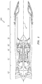
- FIG. 1 schematically illustrates a gas turbine engine 20.
- the gas turbine engine 20 is disclosed herein as a two-spool turbo fan that generally incorporates a fan section 22, a compressor section 24, a combustor section 26 and a turbine section 28.
- another alternative engine architecture 200 might include an augmentor section 12, an exhaust duct section 14 and a nozzle section 16 in addition to the fan section 22', compressor section 24', combustor section 26' and turbine section 28'.
- the fan section 22 drives air along a bypass flowpath and into the compressor section 24.
- the compressor section 24 drives air along a core flowpath for compression and communication into the combustor section 26, which then expands and directs the air through the turbine section 28.
- the engine 20 generally includes a low spool 30 and a high spool 32 mounted for rotation about an engine central longitudinal axis A relative to an engine static structure 36 via several bearing structures 38.
- the low spool 30 generally includes an inner shaft 40 that interconnects a fan 42, a low pressure compressor (“LPC”) 44 and a low pressure turbine (“LPT”) 46.
- the inner shaft 40 drives the fan 42 directly or through a geared architecture 48 to drive the fan 42 at a lower speed than the low spool 30.
- An exemplary reduction transmission is an epicyclic transmission, namely a planetary or star gear system.
- the high spool 32 includes an outer shaft 50 that interconnects a high pressure compressor (“HPC”) 52 and a high pressure turbine (“HPT”) 54.
- a combustor 56 is arranged between the HPC 52 and the HPT 54.
- the inner shaft 40 and the outer shaft 50 are concentric and rotate about the engine central longitudinal axis A which is collinear with their longitudinal axes.
- Core airflow is compressed by the LPC 44 then the HPC 52, mixed with the fuel and burned in the combustor 56, then expanded over the HPT 54 and the LPT 46.
- the LPT 46 and HPT 54 rotationally drive the respective low spool 30 and high spool 32 in response to the expansion.
- the gas turbine engine 20 is a high-bypass geared aircraft engine with a bypass ratio greater than about six (6:1).
- the geared architecture 48 can include an epicyclic gear train, such as a planetary gear system or other gear system.
- the example epicyclic gear train has a gear reduction ratio of greater than about 2.3:1, and in another example, is greater than about 2.5:1.
- the geared turbofan enables operation of the low spool 30 at higher speeds which can increase the operational efficiency of the LPC 44 and LPT 46 to render increased pressure in a fewer number of stages.
- a pressure ratio associated with the LPT 46 is pressure measured prior to the inlet of the LPT 46 as related to the pressure at the outlet of the LPT 46 prior to an exhaust nozzle of the gas turbine engine 20.
- the bypass ratio of the gas turbine engine 20 is greater than about ten (10:1)
- the fan diameter is significantly larger than that of the LPC 44
- the LPT 46 has a pressure ratio greater than about five (5:1). It should be appreciated, however, that the above parameters are only exemplary of a geared architecture engine and that the present disclosure is applicable to other gas turbine engines including direct drive turbofans.
- TSFC Thrust Specific Fuel Consumption
- Fan Pressure Ratio is the pressure ratio across a fan blade of the fan section 22 without the use of a Fan Exit Guide Vane system.
- the low Fan Pressure Ratio according to one example gas turbine engine 20 is less than 1.45.
- Low Corrected Fan Tip Speed is the actual fan tip speed divided by an industry standard temperature correction of ("Tram" / 518.7) 0.5 .
- the Low Corrected Fan Tip Speed according to the example gas turbine engine 20 is less than about 1150 fps (351 m/s).
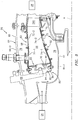
- the combustor section 26 generally includes a combustor 56 with an outer combustor wall assembly 60, an inner combustor wall assembly 62 and a diffuser case module 64.
- the outer combustor wall assembly 60 and the inner combustor wall assembly 62 are spaced apart such that an annular combustion chamber 66 is defined therebetween.
- the outer combustor wall assembly 60 is spaced radially inward from an outer diffuser case 64-0 of the diffuser case module 64 to define an outer annular plenum 76.
- the inner combustor wall assembly 62 is spaced radially outward from an inner diffuser case 64-1 of the diffuser case module 64 to define an inner annular plenum 78. It should be understood that although a particular combustor is illustrated, other combustor types with various combustor wall and diffuser case module arrangements will also benefit herefrom.
- the combustor wall assemblies 60, 62 contain the combustion products for direction toward the turbine section 28.
- Each combustor wall assembly 60, 62 generally includes a respective support shell 68, 70 which supports one or more liner panels 72, 74 mounted within the respective support shell 68, 70.
- Each of the liner panels 72, 74 may be generally rectilinear with a circumferential arc and manufactured of, for example, a nickel based super alloy, ceramic or other temperature resistant material and are arranged to form a liner array.
- the liner array includes a multiple of forward liner panels 72-1 and a multiple of aft liner panels 72-2 that are circumferentially staggered to line the outer shell 68.
- a multiple of forward liner panels 74-1 and a multiple of aft liner panels 74-2 are circumferentially staggered to line the inner shell 70.
- the combustor 56 further includes a forward assembly 80 immediately downstream of the compressor section 24 to receive compressed airflow therefrom.
- the forward assembly 80 generally includes an annular hood 82 and a bulkhead assembly 84 that support a multiple of fuel nozzles 86 (one shown) and a multiple of swirlers 90 (one shown).
- the annular hood 82 extends radially between, and is secured to, the forwardmost ends of the combustor wall assemblies 60, 62.
- the annular hood 82 includes a multiple of circumferentially distributed hood ports 94 each of which accommodates the respective fuel nozzle 86 and introduce air into the forward end of the combustion chamber 66 through a respective swirler 90.
- the bulkhead assembly 84 includes a bulkhead support shell 96 secured to the combustor wall assemblies 60, 62, and a multiple of circumferentially distributed bulkhead liner panels 98 secured to the bulkhead support shell 96.
- Each fuel nozzle 86 may be secured to the diffuser case module 64 and project through one of the hood ports 94 and respective swirlers 90.
- the forward assembly 80 introduces core combustion air into the forward section of the combustion chamber 66 while the remainder enters the outer annular plenum 76 and the inner annular plenum 78.
- the multiple of fuel nozzles 86 and adjacent structure generate a fuel-air mixture that supports stable combustion in the combustion chamber 66.
- the outer and inner support shells 68, 70 are mounted to a first row of Nozzle Guide Vanes (NGVs) 54A in the HPT 54.
- NGVs 54A are static engine components which direct core airflow combustion gases onto turbine blades in the turbine section 28 to facilitate the conversion of pressure energy into kinetic energy.
- the core airflow combustion gases are also accelerated by the NGVs 54A because of their convergent shape and are typically given a "spin” or a "swirl” in the direction of turbine rotor rotation.
- a multiple of studs 100 extend from the liner panels 72, 74 so as to permit the liner panels 72, 74 to be mounted to their respective support shells 68, 70 with fasteners 102 such as nuts. That is, the studs 100 project rigidly from the liner panels 72, 74 through the respective support shells 68, 70 to receive the fasteners 102 at a threaded distal end section thereof to define one or more impingement cavities 106.
- the liner panels 72, 74 typically include one or more rails 120 (see FIG. 5 ) which extend from a cold side 110 thereof.
- the rail 120 typically extends at least around the periphery of the cold side 110 ( FIG. 5 ) to interface with their respective support shells 68, 70 when mounted thereto to define one or more impingement cavities 106. That is, the rails 120 at least extend around the cold side 110 periphery and may include further internal rails to define additional compartments.
- a multiple of cooling impingement passages 104 penetrate through the support shells 68, 70 to allow air from the respective annular plenums 76, 78 to enter impingement cavities 106 formed within the combustor wall assemblies 60, 62 between the respective support shells 68, 70 and liner panels 72, 74.
- the cooling impingement passages 104 are generally normal to the surface of the liner panels 72, 74.
- the air in the impingement cavities 106 provides cold side impingement cooling of the liner panels 72, 74 that is generally defined herein as heat removal via internal convection.
- a multiple of effusion passages 108 penetrate through each of the liner panels 72, 74.
- the geometry of the passages e.g., diameter, shape, density, surface angle, incidence angle, etc.
- the combination of impingement passages 104 and effusion passages 108 for a double wall architecture may be referred to as an Impingement Film Floatwall (IFF) assembly.
- IFF Impingement Film Floatwall
- the effusion passages 108 allow air to pass from each impingement cavity 106 defined in part by the cold side 110 of the liner panels 72, 74 to a hot side 112 thereof to facilitate the formation of a relatively thin, insulating blanket of cooling air along the hot side 112.
- the effusion passages 108 are generally more numerous than the impingement passages 104 to promote the development of a sheath of film cooling along the hot side 112.
- Film cooling as defined herein is the introduction of a relatively cooler air at one or more discrete locations along a surface exposed to a high temperature environment to protect that surface in the region of the air injection as well as downstream thereof.
- Each of the multiple of dilution passages 116 may also penetrate through the respective support shells 68, 70 and liner panels 72, 74 along a common axis D.
- the dilution passages 116 are axially located to dilute the hot combustion gases within the combustion chamber 66 by direct supply of cooling air from the respective annular plenums 76, 78.
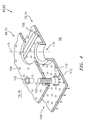
- the multiple rails 120 define two (2) impingement cavities 106A, 106B in this example liner panel 72. It should be appreciated that although two (2) impingement cavities 106A, 106B are illustrated for descriptive purposes in one outer liner panel 72, any number and arrangement of impingement cavities 106 (four shown in FIG. 6 ) will benefit herefrom as well as the inner liner panel 74. It should be appreciated that, although only an example outer liner panel 72 is illustrated in the disclosed non-limiting embodiment, the inner liner panels 74 will also benefit herefrom.
- each impingement cavity 106A, 106B is configured to operate at a different pressure, and thereby defines different controlled pressure drops. That is, impingement cavity 106A operates at a first pressure while impingement cavity 106B operates at a second pressure different than the first pressure.
- Such differential pressure within a single liner panel 72, 74 facilitates, for example, tailored cooling effects for different circumferential and/or axial conditions within the combustion chamber 66.
- the pressure drop across the combustor 56 may be defined as an impingement pressure drop across the support shell 68, 70 and an effusion pressure drop across the liner panels 72, 74 for each impingement cavity 106A, 106B.
- the impingement cavity 106A may define an about 80% impingement pressure drop for impingement flow and about 20% for effusion flow while impingement cavity 106B may provide a 70%-30% split. It should be appreciated that various pressure drop splits may be defined for each impingement cavity 106A, 106B.
- the differential pressure within the impingement cavities 106A, 106B is provided by multiple impingement passages 104 of different diameters for each respective impingement cavity 106A, 106B.
- each impingement passage 104A which communicates with impingement cavity 106A defines a first diameter while each impingement passage 104B which communicates with impingement cavity 106B defines a second diameter different than the first diameter.
- the impingement passages 104A, 104B are laser drilled and thereby readily manufactured and associated with the specific impingement cavity 106A, 106B.
- the differential pressure within the impingement cavities 106A, 106B is obtained by differing ratios of impingement passages 104 (which may or may not be of the same diameter) to effusion passages 108 for the respective impingement cavity 106A, 106B to provide the desired differential pressures within the respective impingement cavities 106A, 106B.
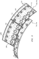
- the differential pressure within the impingement cavities 106A, 106B is provided by a reduced height rail 120A.
- the reduced height rail 120A does not contact the respective support shell 68 and forms an effusion slot 108A between the liner panel 72 and support shell 68 at a trailing edge 140 of each or either of the wall assemblies 60, 62 ( FIG. 10 ).
- the effusion slot 140 is open to the impingement cavity 106B, and thereby varies the pressure drop thereof as the slot 140 operates as an additional effusion passage.
- the reduced height rail 120A may extend circumferentially for only discrete lengths to define circumferential slots 108A ( FIG. 10 ).
- annular impingement cavity 106C may additionally be formed by an annular grommet 150 mounted between the respective support shell 68, 70 and associated liner panels 72, 74.
- the annular grommet 150 permits the respective support shell 68, 70 and associated liner panels 72, 74 to be manufactured as generally consistent flat panels as the annular grommet 150 separately defines the dilution passage 116.
- the impingement cavity 106C is generally annular and defined between the annular grommet 150 and the respective support shell 68, 70. That is, the interface geometry between the annular grommet 150 and the respective support shell 68, 70 defines a generally annular impingement passage 104C.
- the annular grommet 150 abuts the respective liner panel 72, 74 and includes one or more effusion passages 108C therethrough.
- the effusion passages 108C facilitate a relatively high pressure drop as the annular impingement cavity 106C is open to the respective annular plenum 76, 78. It should be appreciated that other geometries may be provided to facilitate formation of the differential pressures and desired controlled pressure drops.
- Controlled pressure drop across the supports shells and respective liner panels facilitates tailored cooling effectiveness for the different boundary conditions of the liner panel hot face. For example, increased pressure drop through the effusion holes provides a greater lifting effect on the hot combustion gases to enhance durability of the liner panels where impinging combustion products pose a potential risk of backflow while reduced pressure drop through the effusion holes is desirable to provide a relatively low velocity flow that remains attached to the hot side of the liner panel.
Description
- The present disclosure relates to a combustor of a gas turbine engine.
- Gas turbine engines, such as those that power modern commercial and military aircraft, generally include a compressor section to pressurize an airflow, a combustor section to burn a hydrocarbon fuel in the presence of the pressurized air, and a turbine section to extract energy from the resultant combustion gases.
- Advanced engine cycles require the combustor section to operate at relatively high compressor exit temperatures. A survey of typical flight envelopes often reveals that high compressor exit temperatures exist with reduced supply pressure at high altitude. These operational conditions may result in relatively high convection and radiation heat loads.
- The combustor section typically includes a double wall assembly with an outer shell that is lined with heat shields, which are often referred to as floatwall liner panels, attached to the outer shell with studs and nuts. In certain arrangements, dilution holes through the double wall combustor direct cooling air for dilution of the combustion gases. In addition to the dilution holes, the outer shell typically includes numerous relatively smaller air impingement holes to direct cooling air between the floatwall panels and the outer shell of the double wall combustor to impingement cool the liner panels. This cooling air then exits effusion holes through the liner panels to form a cooling air film on a hot side of the liner panels that serves as a barrier to facilitate reduction of thermal damage.
- The combustor liner panels may be subject to distress that varies both axially and circumferentially due to the complex turbulent currents of combustion products and dilution air.
- Prior art includes
US 2011/185739 A1 ,WO 2012/133630 A1 ,EP 2180256 A2 ,US 2004/211188 A1 ,US 2010/095679 A1 ,WO 2013/069637 A1 ,WO 2013/192540 A1 which falls under Article 54(3) EPC, andWO 2014/052966 A1 which falls under Article 54(3) EPC. - Document
WO 2013/192540 discloses a combustor of a gas turbine engine, comprising:a support shell defining a multiple of impingement flow passages; anda multiple of liner panels mounted to the support shell, at least one of the multiple of liner panels defines a first impingement cavity with the support shell and a second impingement cavity with the support shell;a first multiple of effusion flow passages through the at least one of the multiple of liner panels and in communication with the first impingement cavity; anda second multiple of effusion flow passages through the at least one of the multiple of liner panels and in communication with the second impingement cavity;wherein the support shell defines a first multiple of impingement flow passages defined in the support shell and in communication with the first impingement cavity, and a second multiple of impingement flow passages defined in the support shell and in communication with the second impingement cavity. - A combustor of a gas turbine engine, according to one disclosed non-limiting embodiment of the present disclosure is claimed in claim 1.
- In a further embodiment of the present disclosure, one of the support shell and the multiple of liner panels includes a rail configured to segregate the first impingement cavity and the second impingement cavity.
- In a further embodiment of any of the foregoing embodiments of the present disclosure, a reduced height rail is included adjacent to the support shell.
- In a further embodiment of any of the foregoing embodiments of the present disclosure, the reduced height rail defines a trailing edge of the at least one of the multiple of liner panels.
- In a further embodiment of any of the foregoing embodiments of the present disclosure, at least one of the first multiple of impingement flow passages defines a diameter different than at least one of the second multiple of impingement flow passages.
- In a further embodiment of any of the foregoing embodiments of the present disclosure, each of the first multiple of impingement flow passages defines a diameter different than each of the second multiple of impingement flow passages.
- In a further embodiment of any of the foregoing embodiments of the present disclosure, the first multiple of impingement flow passages are more numerous than the second multiple of impingement flow passages.
- In a further embodiment of any of the foregoing embodiments of the present disclosure, an annular grommet is included between the support shell and the at least one of the
multiple of liner panels. The annular grommet and the support shell define an annular impingement cavity. - In a further embodiment of any of the foregoing embodiments of the present disclosure, at least one effusion flow passage through the annular grommet and the at least one of the multiple of liner panels.
- A method of cooling a wall assembly within a combustor of a gas turbine engine, according to another disclosed non-limiting embodiment of the present disclosure is claimed in claim 10.
impingement cavity such that the first impingement cavity operates at a first pressure and the second impingement cavity operates at a second pressure different than the pressure. - In a further embodiment of any of the foregoing embodiments of the present disclosure, the method includes directing air from the second impingement cavity through a trailing edge of a liner panel mounted to the support shell.
- In a further embodiment of any of the foregoing embodiments of the present disclosure, the method includes directing air from an annular impingement cavity at least partially defined by an annular grommet between the support shell and the liner panel.
- In a further embodiment of any of the foregoing embodiments of the present disclosure, the method includes forming a first impingement pressure drop across the support shell in the first impingement cavity and a second impingement pressure drop across the support shell in the second impingement cavity, the first impingement pressure drop different than the second impingement pressure drop.
- In a further embodiment of any of the foregoing embodiments of the present disclosure, the method includes forming a first effusion pressure drop across the liner panel with respect to the first impingement cavity and a second effusion pressure drop across the liner panel with respect to the second impingement cavity, the first effusion pressure drop different than the second effusion pressure drop.
- The foregoing features and elements may be combined in various combinations without exclusivity, unless expressly indicated otherwise. These features and elements as well as the operation thereof will become more apparent in light of the following description and the accompanying drawings. It should be understood, however, the following description and drawings are intended to be exemplary in nature and non-limiting.
- Various features will become apparent to those skilled in the art from the following detailed description of the disclosed non-limiting embodiment. The drawings that accompany the detailed description can be briefly described as follows:
-
FIG. 1 is a schematic cross-section of an example gas turbine engine architecture; -
FIG. 2 is a schematic cross-section of another example gas turbine engine architecture; -
FIG. 3 is an expanded longitudinal schematic sectional view of a combustor section according to one non-limiting embodiment that may be used with the example gas turbine engine architectures shown inFIGS. 1 and2 ; -
FIG. 4 is an expanded exploded view of a combustor wall assembly; -
FIG. 5 is a perspective cold side view of a portion of an outer liner panel array; -
FIG. 6 is a perspective cold side view of one liner panel according to another disclosed non-limiting embodiment; -
FIG. 7 is a sectional view of a combustor wall assembly according to one disclosed non-limiting embodiment; -
FIG. 8 is a sectional view of a combustor wall assembly according to another disclosed non-limiting embodiment; -
FIG. 9 is a sectional view of a combustor wall assembly according to another disclosed non-limiting embodiment; -
FIG. 10 is a trailing edge view of the combustor wall assembly ofFIG. 9 ; and -
FIG. 11 is a sectional view of a combustor wall assembly according to another disclosed non-limiting embodiment. -
FIG. 1 schematically illustrates agas turbine engine 20. Thegas turbine engine 20 is disclosed herein as a two-spool turbo fan that generally incorporates afan section 22, acompressor section 24, acombustor section 26 and aturbine section 28. Referring toFIG. 2 , anotheralternative engine architecture 200 might include anaugmentor section 12, anexhaust duct section 14 and anozzle section 16 in addition to the fan section 22', compressor section 24', combustor section 26' and turbine section 28'. Although depicted as an aero engine in the disclosed non-limiting embodiments, it should be understood that the concepts described herein are not so limited and the teachings may be applied to other types of turbine engines such as a turbojets, turboshafts, and three-spool (plus fan) turbofans with an intermediate spool as well as industrial gas turbines. - Referring to
FIG. 1 , thefan section 22 drives air along a bypass flowpath and into thecompressor section 24. Thecompressor section 24 drives air along a core flowpath for compression and communication into thecombustor section 26, which then expands and directs the air through theturbine section 28. Theengine 20 generally includes alow spool 30 and ahigh spool 32 mounted for rotation about an engine central longitudinal axis A relative to an enginestatic structure 36 viaseveral bearing structures 38. Thelow spool 30 generally includes aninner shaft 40 that interconnects afan 42, a low pressure compressor ("LPC") 44 and a low pressure turbine ("LPT") 46. Theinner shaft 40 drives thefan 42 directly or through a gearedarchitecture 48 to drive thefan 42 at a lower speed than thelow spool 30. An exemplary reduction transmission is an epicyclic transmission, namely a planetary or star gear system. - The
high spool 32 includes anouter shaft 50 that interconnects a high pressure compressor ("HPC") 52 and a high pressure turbine ("HPT") 54. Acombustor 56 is arranged between the HPC 52 and the HPT 54. Theinner shaft 40 and theouter shaft 50 are concentric and rotate about the engine central longitudinal axis A which is collinear with their longitudinal axes. - Core airflow is compressed by the
LPC 44 then the HPC 52, mixed with the fuel and burned in thecombustor 56, then expanded over the HPT 54 and theLPT 46. TheLPT 46 and HPT 54 rotationally drive the respectivelow spool 30 andhigh spool 32 in response to the expansion. - In one non-limiting example, the
gas turbine engine 20 is a high-bypass geared aircraft engine with a bypass ratio greater than about six (6:1). The gearedarchitecture 48 can include an epicyclic gear train, such as a planetary gear system or other gear system. The example epicyclic gear train has a gear reduction ratio of greater than about 2.3:1, and in another example, is greater than about 2.5:1. The geared turbofan enables operation of thelow spool 30 at higher speeds which can increase the operational efficiency of theLPC 44 andLPT 46 to render increased pressure in a fewer number of stages. - A pressure ratio associated with the
LPT 46 is pressure measured prior to the inlet of theLPT 46 as related to the pressure at the outlet of theLPT 46 prior to an exhaust nozzle of thegas turbine engine 20. In another non-limiting example, the bypass ratio of thegas turbine engine 20 is greater than about ten (10:1), the fan diameter is significantly larger than that of theLPC 44, and theLPT 46 has a pressure ratio greater than about five (5:1). It should be appreciated, however, that the above parameters are only exemplary of a geared architecture engine and that the present disclosure is applicable to other gas turbine engines including direct drive turbofans. - In an example high-bypass turbofan, significant thrust is provided by the high bypass ratio as the
fan section 22 may be designed for a particular flight condition - typically cruise at about 0.8 Mach and about 35,000 feet. This flight condition, with thegas turbine engine 20 at its best fuel consumption, is also known as bucket cruise Thrust Specific Fuel Consumption (TSFC) which is an industry standard parameter of fuel consumption per unit of thrust. - Fan Pressure Ratio is the pressure ratio across a fan blade of the
fan section 22 without the use of a Fan Exit Guide Vane system. The low Fan Pressure Ratio according to one examplegas turbine engine 20 is less than 1.45. Low Corrected Fan Tip Speed is the actual fan tip speed divided by an industry standard temperature correction of ("Tram" / 518.7)0.5. The Low Corrected Fan Tip Speed according to the examplegas turbine engine 20 is less than about 1150 fps (351 m/s). - With reference to
FIG. 3 , thecombustor section 26 generally includes acombustor 56 with an outercombustor wall assembly 60, an innercombustor wall assembly 62 and adiffuser case module 64. The outercombustor wall assembly 60 and the innercombustor wall assembly 62 are spaced apart such that anannular combustion chamber 66 is defined therebetween. - The outer
combustor wall assembly 60 is spaced radially inward from an outer diffuser case 64-0 of thediffuser case module 64 to define an outerannular plenum 76. The innercombustor wall assembly 62 is spaced radially outward from an inner diffuser case 64-1 of thediffuser case module 64 to define an innerannular plenum 78. It should be understood that although a particular combustor is illustrated, other combustor types with various combustor wall and diffuser case module arrangements will also benefit herefrom. - The
combustor wall assemblies turbine section 28. Eachcombustor wall assembly respective support shell respective support shell outer shell 68. A multiple of forward liner panels 74-1 and a multiple of aft liner panels 74-2 are circumferentially staggered to line theinner shell 70. - The
combustor 56 further includes aforward assembly 80 immediately downstream of thecompressor section 24 to receive compressed airflow therefrom. Theforward assembly 80 generally includes anannular hood 82 and abulkhead assembly 84 that support a multiple of fuel nozzles 86 (one shown) and a multiple of swirlers 90 (one shown). Theannular hood 82 extends radially between, and is secured to, the forwardmost ends of thecombustor wall assemblies annular hood 82 includes a multiple of circumferentially distributedhood ports 94 each of which accommodates therespective fuel nozzle 86 and introduce air into the forward end of thecombustion chamber 66 through arespective swirler 90. Thebulkhead assembly 84 includes abulkhead support shell 96 secured to thecombustor wall assemblies bulkhead liner panels 98 secured to thebulkhead support shell 96. Eachfuel nozzle 86 may be secured to thediffuser case module 64 and project through one of thehood ports 94 andrespective swirlers 90. - The
forward assembly 80 introduces core combustion air into the forward section of thecombustion chamber 66 while the remainder enters the outerannular plenum 76 and the innerannular plenum 78. The multiple offuel nozzles 86 and adjacent structure generate a fuel-air mixture that supports stable combustion in thecombustion chamber 66. - Opposite the
forward assembly 80, the outer andinner support shells HPT 54. TheNGVs 54A are static engine components which direct core airflow combustion gases onto turbine blades in theturbine section 28 to facilitate the conversion of pressure energy into kinetic energy. The core airflow combustion gases are also accelerated by theNGVs 54A because of their convergent shape and are typically given a "spin" or a "swirl" in the direction of turbine rotor rotation. - With reference to
FIG. 4 , a multiple ofstuds 100 extend from the liner panels 72, 74 so as to permit the liner panels 72, 74 to be mounted to theirrespective support shells fasteners 102 such as nuts. That is, thestuds 100 project rigidly from the liner panels 72, 74 through therespective support shells fasteners 102 at a threaded distal end section thereof to define one ormore impingement cavities 106. The liner panels 72, 74 typically include one or more rails 120 (seeFIG. 5 ) which extend from acold side 110 thereof. Therail 120 typically extends at least around the periphery of the cold side 110 (FIG. 5 ) to interface with theirrespective support shells more impingement cavities 106. That is, therails 120 at least extend around thecold side 110 periphery and may include further internal rails to define additional compartments. - A multiple of cooling
impingement passages 104 penetrate through thesupport shells annular plenums impingement cavities 106 formed within thecombustor wall assemblies respective support shells impingement passages 104 are generally normal to the surface of the liner panels 72, 74. The air in theimpingement cavities 106 provides cold side impingement cooling of the liner panels 72, 74 that is generally defined herein as heat removal via internal convection. - A multiple of
effusion passages 108 penetrate through each of the liner panels 72, 74. The geometry of the passages (e.g., diameter, shape, density, surface angle, incidence angle, etc.) as well as the location of the passages with respect to the high temperature combustion gas flow within thecombustion chamber 66 also contributes to effusion film cooling. The combination ofimpingement passages 104 andeffusion passages 108 for a double wall architecture may be referred to as an Impingement Film Floatwall (IFF) assembly. - The
effusion passages 108 allow air to pass from eachimpingement cavity 106 defined in part by thecold side 110 of the liner panels 72, 74 to ahot side 112 thereof to facilitate the formation of a relatively thin, insulating blanket of cooling air along thehot side 112. Theeffusion passages 108 are generally more numerous than theimpingement passages 104 to promote the development of a sheath of film cooling along thehot side 112. Film cooling as defined herein is the introduction of a relatively cooler air at one or more discrete locations along a surface exposed to a high temperature environment to protect that surface in the region of the air injection as well as downstream thereof. - Each of the multiple of
dilution passages 116 may also penetrate through therespective support shells dilution passages 116 are axially located to dilute the hot combustion gases within thecombustion chamber 66 by direct supply of cooling air from the respectiveannular plenums - With reference to
FIG. 7 , in one disclosed non-limiting embodiment, themultiple rails 120 define two (2)impingement cavities impingement cavities FIG. 6 ) will benefit herefrom as well as the inner liner panel 74. It should be appreciated that, although only an example outer liner panel 72 is illustrated in the disclosed non-limiting embodiment, the inner liner panels 74 will also benefit herefrom. - As further discussed below, each
impingement cavity impingement cavity 106A operates at a first pressure whileimpingement cavity 106B operates at a second pressure different than the first pressure. Such differential pressure within a single liner panel 72, 74 facilitates, for example, tailored cooling effects for different circumferential and/or axial conditions within thecombustion chamber 66. - The pressure drop across the
combustor 56 may be defined as an impingement pressure drop across thesupport shell impingement cavity impingement cavity 106A may define an about 80% impingement pressure drop for impingement flow and about 20% for effusion flow whileimpingement cavity 106B may provide a 70%-30% split. It should be appreciated that various pressure drop splits may be defined for eachimpingement cavity - With continued reference to
FIG. 7 , according to one disclosed non-limiting embodiment, the differential pressure within the impingement cavities 106A, 106B is provided by multipleimpingement passages 104 of different diameters for eachrespective impingement cavity impingement passage 104A which communicates withimpingement cavity 106A defines a first diameter while eachimpingement passage 104B which communicates withimpingement cavity 106B defines a second diameter different than the first diameter. In this disclosed non-limiting embodiment, theimpingement passages specific impingement cavity - With reference to
FIG. 8 , according to another disclosed non-limiting embodiment, the differential pressure within the impingement cavities 106A, 106B is obtained by differing ratios of impingement passages 104 (which may or may not be of the same diameter) toeffusion passages 108 for therespective impingement cavity respective impingement cavities - With reference to
FIG. 9 , according to another disclosed non-limiting embodiment, the differential pressure within the impingement cavities 106A, 106B is provided by a reducedheight rail 120A. The reducedheight rail 120A does not contact therespective support shell 68 and forms aneffusion slot 108A between the liner panel 72 andsupport shell 68 at a trailingedge 140 of each or either of thewall assemblies 60, 62 (FIG. 10 ). Theeffusion slot 140 is open to theimpingement cavity 106B, and thereby varies the pressure drop thereof as theslot 140 operates as an additional effusion passage. It should be appreciated that the reducedheight rail 120A may extend circumferentially for only discrete lengths to definecircumferential slots 108A (FIG. 10 ). - With reference to
FIG. 11 , according to another disclosed non-limiting embodiment, anannular impingement cavity 106C may additionally be formed by anannular grommet 150 mounted between therespective support shell annular grommet 150 permits therespective support shell annular grommet 150 separately defines thedilution passage 116. In this disclosed non-limiting embodiment, theimpingement cavity 106C is generally annular and defined between theannular grommet 150 and therespective support shell annular grommet 150 and therespective support shell annular impingement passage 104C. Theannular grommet 150 abuts the respective liner panel 72, 74 and includes one ormore effusion passages 108C therethrough. Theeffusion passages 108C facilitate a relatively high pressure drop as theannular impingement cavity 106C is open to the respectiveannular plenum - Controlled pressure drop across the supports shells and respective liner panels facilitates tailored cooling effectiveness for the different boundary conditions of the liner panel hot face. For example, increased pressure drop through the effusion holes provides a greater lifting effect on the hot combustion gases to enhance durability of the liner panels where impinging combustion products pose a potential risk of backflow while reduced pressure drop through the effusion holes is desirable to provide a relatively low velocity flow that remains attached to the hot side of the liner panel.
- The use of the terms "a" and "an" and "the" and similar references in the context of description (especially in the context of the following claims) are to be construed to cover both the singular and the plural, unless otherwise indicated herein or specifically contradicted by context. The modifier "about" used in connection with a quantity is inclusive of the stated value and has the meaning dictated by the context (e.g., it includes the degree of error associated with measurement of the particular quantity). All ranges disclosed herein are inclusive of the endpoints, and the endpoints are independently combinable with each other. It should be appreciated that relative positional terms such as "forward," "aft," "upper," "lower," "above," "below," and the like are with reference to the normal operational attitude of the vehicle and should not be considered otherwise limiting.
- Although the different non-limiting embodiments have specific illustrated components, the embodiments of this invention are not limited to those particular combinations. It is possible to use some of the components or features from any of the non-limiting embodiments in combination with features or components from any of the other non-limiting embodiments.
- It should be appreciated that like reference numerals identify corresponding or similar elements throughout the several drawings. It should also be appreciated that although a particular component arrangement is disclosed in the illustrated embodiment, other arrangements will benefit herefrom.
- Although particular step sequences are shown, described, and claimed, it should be understood that steps may be performed in any order, separated or combined unless otherwise indicated and will still benefit from the present disclosure.
Claims (13)
- A combustor (56) of a gas turbine engine (20), comprising:a support shell (68,70) defining a multiple of impingement flow passages (104); anda multiple of liner panels (72,74) mounted to the support shell (68,70), at least one of the multiple of liner panels (72,74) defines a first impingement cavity (106A) with the support shell (68, 70) and a second impingement cavity (106B) with the support shell;a first multiple of effusion flow passages (108) through the at least one of the multiple of liner panels (72, 74) and in communication with the first impingement cavity (106A); anda second multiple of effusion flow passages (108) through the at least one of the multiple of liner panels (72, 74) and in communication with the second impingement cavity (106B);wherein the support shell (68,70) defines a first multiple of impingement flow passages (104A) defined in the support shell (68,70) and in communication with the first impingement cavity (106A), and a second multiple of impingement flow passages (104B) defined in the support shell (68,70) and in communication with the second impingement cavity (106B); whereinthe first multiple of impingement flow passages (104A) and the first multiple of effusion flow passages (108) define a first ratio and the second multiple of impingement flow passages (104B) and the second multiple of effusion flow passages (108) define a second ratio, the first ratio different than the second ratio such that the first impingement cavity (106A) is operable at a first pressure and the second impingement cavity (106B) is operable at a second pressure different than said first pressure.
- The combustor as recited in claim 1, wherein one of the support shell (68,70) and the multiple of liner panels (72,74) includes a rail (120) configured to segregate the first impingement cavity (106A) and the second impingement cavity (106B).
- The combustor as recited in claim 2, further comprising a reduced height rail (120A) adjacent to the support shell (68,70).
- The combustor as recited in claim 3, wherein the reduced height rail (120A) defines a trailing edge (140) of the at least one of the multiple of liner panels (72,74).
- The combustor as recited in any preceding claim, wherein:at least one of the first multiple of impingement flow passages (104A) defines a diameter different than at least one of the second multiple of impingement flow passages (104B);each of the first multiple of impingement flow passages (104A) defines a diameter different than each of the second multiple of impingement flow passages (104B).
- The combustor as recited in any preceding claim, wherein the first multiple of impingement flow passages (104A) are more numerous than the second multiple of impingement flow passages (104B).
- The combustor as recited in any preceding claim, further comprising an annular grommet (150) between the support shell (68,70) and the at least one of the multiple of liner panels (72,74), the annular grommet (150) and the support shell (68,70) defines an annular impingement cavity (106C), and at least one effusion flow passage (108) through the annular grommet (150) and the at least one of the multiple of liner panels (68,70).
- The combustor as recited in claim 1, wherein said multiple of liner panels (68,70) includes a first liner panel including the first impingement cavity (106A) and a second liner panel including the second impingement cavity (106B), the combustor (56) further comprising a plurality of studs (100) which extend from a cold side of each of the multiple of liner panels, the studs (100) extending through the support shell.
- The combustor as recited in claim 8, further comprising:a first rail (120) around a periphery of the first liner panel; anda second rail (120) around a periphery of the second liner panel;the first rail and the second rail in contact with the support shell (68,70) to segregate the first liner panel and the second liner panel.
- A method of cooling a wall assembly within a combustor (56) of a gas turbine engine (20), comprising:defining a first multiple of effusion flow passages (108) through at least one of the multiple of liner panels (72,74) and in communication with a first impingement cavity (106A), and defining a second multiple of effusion flow passages (108) through the at least one of the multiple of liner panels (72,74) and in communication with a second impingement cavity (106B);defining a first multiple of impingement flow passages (104A) in a support shell (68,70) and in communication with the first impingement cavity (106A), and a second multiple of impingement flow passages (104B) in the support shell (68,70) and in communication with the second impingement cavity (106B); whereinthe first multiple of impingement flow passages (104A) and the first multiple of effusion flow passages (108) define a first ratio and the second multiple of impingement flow passages (104B) and the second multiple of effusion flow passages (108) define a second ratio, the first ratio different than the second ratio such that the first impingement cavity (106A) operates at a first pressure and the second impingement cavity (106B) operates at a second pressure different than said first pressure.
- The method as recited in claim 10, further comprising directing air from the second impingement cavity (106B) through a trailing edge (140) of the at least one of the liner panels (72,74) mounted to the support shell (68,70), or directing air from an annular impingement cavity (106C) at least partially defined by an annular grommet (150) between the support shell (68,70) and the at least one of the liner panels (72,74).
- The method as recited in claim 10 or 11, further comprising forming a first impingement pressure drop across the support shell (68,70) in the first impingement cavity (106A) and a second impingement pressure drop across the support shell (68,70) in the second impingement cavity (106B), the first impingement pressure drop different than the second impingement pressure drop.
- The method as recited in claim 10, 11 or 12, further comprising forming a first effusion pressure drop across the at least one of the liner panels (72,74) with respect to the first impingement cavity (106A) and a second effusion pressure drop across the at least one of the liner panels (72,74) with respect to the second impingement cavity (106B), the first effusion pressure drop different than the second effusion pressure drop.
Applications Claiming Priority (2)
| Application Number | Priority Date | Filing Date | Title |
|---|---|---|---|
| US201361878327P | 2013-09-16 | 2013-09-16 | |
| PCT/US2014/055784 WO2015039074A1 (en) | 2013-09-16 | 2014-09-16 | Controlled variation of pressure drop through effusion cooling in a double walled combustor of a gas turbine engine |
Publications (3)
| Publication Number | Publication Date |
|---|---|
| EP3047128A1 EP3047128A1 (en) | 2016-07-27 |
| EP3047128A4 EP3047128A4 (en) | 2016-08-24 |
| EP3047128B1 true EP3047128B1 (en) | 2018-10-31 |
Family
ID=52666406
Family Applications (1)
| Application Number | Title | Priority Date | Filing Date |
|---|---|---|---|
| EP14844554.7A Active EP3047128B1 (en) | 2013-09-16 | 2014-09-16 | Controlled variation of pressure drop through effusion cooling in a double walled combustor of a gas turbine engine |
Country Status (3)
| Country | Link |
|---|---|
| US (1) | US10731858B2 (en) |
| EP (1) | EP3047128B1 (en) |
| WO (1) | WO2015039074A1 (en) |
Families Citing this family (10)
| Publication number | Priority date | Publication date | Assignee | Title |
|---|---|---|---|---|
| GB201418042D0 (en) * | 2014-10-13 | 2014-11-26 | Rolls Royce Plc | A liner element for a combustor, and a related method |
| US9803863B2 (en) * | 2015-05-13 | 2017-10-31 | Solar Turbines Incorporated | Controlled-leak combustor grommet |
| GB201518345D0 (en) | 2015-10-16 | 2015-12-02 | Rolls Royce | Combustor for a gas turbine engine |
| GB201613208D0 (en) | 2016-08-01 | 2016-09-14 | Rolls Royce Plc | A combustion chamber assembly and a combustion chamber segment |
| US11143401B2 (en) * | 2017-12-22 | 2021-10-12 | Raytheon Technologies Corporation | Apparatus and method for mitigating particulate accumulation on a component of a gas turbine |
| US11486578B2 (en) | 2020-05-26 | 2022-11-01 | Raytheon Technologies Corporation | Multi-walled structure for a gas turbine engine |
| US11371701B1 (en) | 2021-02-03 | 2022-06-28 | General Electric Company | Combustor for a gas turbine engine |
| US11885495B2 (en) | 2021-06-07 | 2024-01-30 | General Electric Company | Combustor for a gas turbine engine including a liner having a looped feature |
| US11774098B2 (en) | 2021-06-07 | 2023-10-03 | General Electric Company | Combustor for a gas turbine engine |
| US11959643B2 (en) | 2021-06-07 | 2024-04-16 | General Electric Company | Combustor for a gas turbine engine |
Family Cites Families (36)
| Publication number | Priority date | Publication date | Assignee | Title |
|---|---|---|---|---|
| US553864A (en) * | 1896-02-04 | Running-gear for vehicles | ||
| US4132066A (en) * | 1977-09-23 | 1979-01-02 | United Technologies Corporation | Combustor liner for gas turbine engine |
| US4653279A (en) * | 1985-01-07 | 1987-03-31 | United Technologies Corporation | Integral refilmer lip for floatwall panels |
| US5331816A (en) | 1992-10-13 | 1994-07-26 | United Technologies Corporation | Gas turbine engine combustor fiber reinforced glass ceramic matrix liner with embedded refractory ceramic tiles |
| JP3110227B2 (en) * | 1993-11-22 | 2000-11-20 | 株式会社東芝 | Turbine cooling blade |
| US6205789B1 (en) | 1998-11-13 | 2001-03-27 | General Electric Company | Multi-hole film cooled combuster liner |
| GB9926257D0 (en) | 1999-11-06 | 2000-01-12 | Rolls Royce Plc | Wall elements for gas turbine engine combustors |
| GB2361303B (en) | 2000-04-14 | 2004-10-20 | Rolls Royce Plc | Wall structure for a gas turbine engine combustor |
| US6606861B2 (en) | 2001-02-26 | 2003-08-19 | United Technologies Corporation | Low emissions combustor for a gas turbine engine |
| DE10155420A1 (en) | 2001-11-12 | 2003-05-22 | Rolls Royce Deutschland | Heat shield arrangement with sealing element |
| DE10214570A1 (en) | 2002-04-02 | 2004-01-15 | Rolls-Royce Deutschland Ltd & Co Kg | Mixed air hole in gas turbine combustion chamber with combustion chamber shingles |
| US7086232B2 (en) | 2002-04-29 | 2006-08-08 | General Electric Company | Multihole patch for combustor liner of a gas turbine engine |
| GB0305025D0 (en) | 2003-03-05 | 2003-04-09 | Alstom Switzerland Ltd | Method and device for efficient usage of cooling air for acoustic damping of combustion chamber pulsations |
| US6964170B2 (en) | 2003-04-28 | 2005-11-15 | Pratt & Whitney Canada Corp. | Noise reducing combustor |
| US7146815B2 (en) | 2003-07-31 | 2006-12-12 | United Technologies Corporation | Combustor |
| EP1507116A1 (en) | 2003-08-13 | 2005-02-16 | Siemens Aktiengesellschaft | Heat shield arrangement for a high temperature gas conveying component, in particular for a gas turbine combustion chamber |
| US7093441B2 (en) | 2003-10-09 | 2006-08-22 | United Technologies Corporation | Gas turbine annular combustor having a first converging volume and a second converging volume, converging less gradually than the first converging volume |
| US7363763B2 (en) | 2003-10-23 | 2008-04-29 | United Technologies Corporation | Combustor |
| US7018176B2 (en) * | 2004-05-06 | 2006-03-28 | United Technologies Corporation | Cooled turbine airfoil |
| US7464554B2 (en) | 2004-09-09 | 2008-12-16 | United Technologies Corporation | Gas turbine combustor heat shield panel or exhaust panel including a cooling device |
| US7954325B2 (en) | 2005-12-06 | 2011-06-07 | United Technologies Corporation | Gas turbine combustor |
| GB2453946B (en) | 2007-10-23 | 2010-07-14 | Rolls Royce Plc | A Wall Element for use in Combustion Apparatus |
| GB0801839D0 (en) | 2008-02-01 | 2008-03-05 | Rolls Royce Plc | combustion apparatus |
| US20100095680A1 (en) | 2008-10-22 | 2010-04-22 | Honeywell International Inc. | Dual wall structure for use in a combustor of a gas turbine engine |
| US20100095679A1 (en) * | 2008-10-22 | 2010-04-22 | Honeywell International Inc. | Dual wall structure for use in a combustor of a gas turbine engine |
| US8348613B2 (en) * | 2009-03-30 | 2013-01-08 | United Technologies Corporation | Airflow influencing airfoil feature array |
| CN103925015B (en) * | 2009-08-24 | 2016-01-20 | 三菱重工业株式会社 | Segmentation ring cooling structure and gas turbine |
| US20110185739A1 (en) | 2010-01-29 | 2011-08-04 | Honeywell International Inc. | Gas turbine combustors with dual walled liners |
| US9010121B2 (en) * | 2010-12-10 | 2015-04-21 | Rolls-Royce Plc | Combustion chamber |
| JP5696566B2 (en) | 2011-03-31 | 2015-04-08 | 株式会社Ihi | Combustor for gas turbine engine and gas turbine engine |
| US9222674B2 (en) | 2011-07-21 | 2015-12-29 | United Technologies Corporation | Multi-stage amplification vortex mixture for gas turbine engine combustor |
| US8978385B2 (en) | 2011-07-29 | 2015-03-17 | United Technologies Corporation | Distributed cooling for gas turbine engine combustor |
| JP5821550B2 (en) | 2011-11-10 | 2015-11-24 | 株式会社Ihi | Combustor liner |
| US20130298564A1 (en) * | 2012-05-14 | 2013-11-14 | General Electric Company | Cooling system and method for turbine system |
| US9052111B2 (en) | 2012-06-22 | 2015-06-09 | United Technologies Corporation | Turbine engine combustor wall with non-uniform distribution of effusion apertures |
| EP2900975A4 (en) | 2012-09-28 | 2016-05-04 | United Technologies Corp | Combustor section of a gas turbine engine |
-
2014
- 2014-09-16 WO PCT/US2014/055784 patent/WO2015039074A1/en active Application Filing
- 2014-09-16 EP EP14844554.7A patent/EP3047128B1/en active Active
- 2014-09-16 US US14/913,795 patent/US10731858B2/en active Active
Non-Patent Citations (1)
| Title |
|---|
| None * |
Also Published As
| Publication number | Publication date |
|---|---|
| WO2015039074A1 (en) | 2015-03-19 |
| US10731858B2 (en) | 2020-08-04 |
| EP3047128A4 (en) | 2016-08-24 |
| US20160356500A1 (en) | 2016-12-08 |
| EP3047128A1 (en) | 2016-07-27 |
Similar Documents
| Publication | Publication Date | Title |
|---|---|---|
| EP3047128B1 (en) | Controlled variation of pressure drop through effusion cooling in a double walled combustor of a gas turbine engine | |
| EP2959136B1 (en) | Gas turbine engine combustor provided with finned ignitor grommet | |
| US20160123592A1 (en) | Gas turbine engine combustor liner panel | |
| EP3077728B1 (en) | Gas turbine engine combustor having co-swirl orientation of combustor effusion passages, and method | |
| US10488046B2 (en) | Gas turbine engine combustor bulkhead assembly | |
| EP3008386B1 (en) | Gas turbine engine combustor liner panel | |
| EP2932070B1 (en) | Gas turbine engine combustor heat shield with increased film cooling effectiveness | |
| US20160186998A1 (en) | Contoured dilution passages for gas turbine engine combustor | |
| US10816201B2 (en) | Sealed combustor liner panel for a gas turbine engine | |
| US20160201908A1 (en) | Vena contracta swirling dilution passages for gas turbine engine combustor | |
| US10508808B2 (en) | Gas turbine engine wave geometry combustor liner panel | |
| EP3315730A1 (en) | Combustor seal for a gas turbine engine combustor | |
| US20160334103A1 (en) | Dilution passage arrangement for gas turbine engine combustor | |
| EP3315862B1 (en) | Cast combustor liner panel with a radius edge for gas turbine engine combustor |
Legal Events
| Date | Code | Title | Description |
|---|---|---|---|
| PUAI | Public reference made under article 153(3) epc to a published international application that has entered the european phase |
Free format text: ORIGINAL CODE: 0009012 |
|
| 17P | Request for examination filed |
Effective date: 20160418 |
|
| AK | Designated contracting states |
Kind code of ref document: A1 Designated state(s): AL AT BE BG CH CY CZ DE DK EE ES FI FR GB GR HR HU IE IS IT LI LT LU LV MC MK MT NL NO PL PT RO RS SE SI SK SM TR |
|
| AX | Request for extension of the european patent |
Extension state: BA ME |
|
| A4 | Supplementary search report drawn up and despatched |
Effective date: 20160726 |
|
| RIC1 | Information provided on ipc code assigned before grant |
Ipc: F23R 3/04 20060101ALI20160720BHEP Ipc: F02C 7/12 20060101AFI20160720BHEP Ipc: F23R 3/06 20060101ALI20160720BHEP Ipc: F02C 7/24 20060101ALI20160720BHEP Ipc: F23M 5/04 20060101ALI20160720BHEP Ipc: F23R 3/42 20060101ALI20160720BHEP |
|
| RAP1 | Party data changed (applicant data changed or rights of an application transferred) |
Owner name: UNITED TECHNOLOGIES CORPORATION |
|
| DAX | Request for extension of the european patent (deleted) | ||
| STAA | Information on the status of an ep patent application or granted ep patent |
Free format text: STATUS: REQUEST FOR EXAMINATION WAS MADE |
|
| GRAP | Despatch of communication of intention to grant a patent |
Free format text: ORIGINAL CODE: EPIDOSNIGR1 |
|
| STAA | Information on the status of an ep patent application or granted ep patent |
Free format text: STATUS: GRANT OF PATENT IS INTENDED |
|
| INTG | Intention to grant announced |
Effective date: 20180420 |
|
| GRAS | Grant fee paid |
Free format text: ORIGINAL CODE: EPIDOSNIGR3 |
|
| GRAA | (expected) grant |
Free format text: ORIGINAL CODE: 0009210 |
|
| STAA | Information on the status of an ep patent application or granted ep patent |
Free format text: STATUS: THE PATENT HAS BEEN GRANTED |
|
| AK | Designated contracting states |
Kind code of ref document: B1 Designated state(s): AL AT BE BG CH CY CZ DE DK EE ES FI FR GB GR HR HU IE IS IT LI LT LU LV MC MK MT NL NO PL PT RO RS SE SI SK SM TR |
|
| REG | Reference to a national code |
Ref country code: CH Ref legal event code: EP Ref country code: GB Ref legal event code: FG4D |
|
| REG | Reference to a national code |
Ref country code: AT Ref legal event code: REF Ref document number: 1059694 Country of ref document: AT Kind code of ref document: T Effective date: 20181115 |
|
| REG | Reference to a national code |
Ref country code: IE Ref legal event code: FG4D |
|
| REG | Reference to a national code |
Ref country code: DE Ref legal event code: R096 Ref document number: 602014035309 Country of ref document: DE |
|
| REG | Reference to a national code |
Ref country code: NL Ref legal event code: MP Effective date: 20181031 |
|
| REG | Reference to a national code |
Ref country code: LT Ref legal event code: MG4D |
|
| REG | Reference to a national code |
Ref country code: AT Ref legal event code: MK05 Ref document number: 1059694 Country of ref document: AT Kind code of ref document: T Effective date: 20181031 |
|
| PG25 | Lapsed in a contracting state [announced via postgrant information from national office to epo] |
Ref country code: FI Free format text: LAPSE BECAUSE OF FAILURE TO SUBMIT A TRANSLATION OF THE DESCRIPTION OR TO PAY THE FEE WITHIN THE PRESCRIBED TIME-LIMIT Effective date: 20181031 Ref country code: BG Free format text: LAPSE BECAUSE OF FAILURE TO SUBMIT A TRANSLATION OF THE DESCRIPTION OR TO PAY THE FEE WITHIN THE PRESCRIBED TIME-LIMIT Effective date: 20190131 Ref country code: PL Free format text: LAPSE BECAUSE OF FAILURE TO SUBMIT A TRANSLATION OF THE DESCRIPTION OR TO PAY THE FEE WITHIN THE PRESCRIBED TIME-LIMIT Effective date: 20181031 Ref country code: HR Free format text: LAPSE BECAUSE OF FAILURE TO SUBMIT A TRANSLATION OF THE DESCRIPTION OR TO PAY THE FEE WITHIN THE PRESCRIBED TIME-LIMIT Effective date: 20181031 Ref country code: LV Free format text: LAPSE BECAUSE OF FAILURE TO SUBMIT A TRANSLATION OF THE DESCRIPTION OR TO PAY THE FEE WITHIN THE PRESCRIBED TIME-LIMIT Effective date: 20181031 Ref country code: AT Free format text: LAPSE BECAUSE OF FAILURE TO SUBMIT A TRANSLATION OF THE DESCRIPTION OR TO PAY THE FEE WITHIN THE PRESCRIBED TIME-LIMIT Effective date: 20181031 Ref country code: IS Free format text: LAPSE BECAUSE OF FAILURE TO SUBMIT A TRANSLATION OF THE DESCRIPTION OR TO PAY THE FEE WITHIN THE PRESCRIBED TIME-LIMIT Effective date: 20190228 Ref country code: ES Free format text: LAPSE BECAUSE OF FAILURE TO SUBMIT A TRANSLATION OF THE DESCRIPTION OR TO PAY THE FEE WITHIN THE PRESCRIBED TIME-LIMIT Effective date: 20181031 Ref country code: LT Free format text: LAPSE BECAUSE OF FAILURE TO SUBMIT A TRANSLATION OF THE DESCRIPTION OR TO PAY THE FEE WITHIN THE PRESCRIBED TIME-LIMIT Effective date: 20181031 Ref country code: NO Free format text: LAPSE BECAUSE OF FAILURE TO SUBMIT A TRANSLATION OF THE DESCRIPTION OR TO PAY THE FEE WITHIN THE PRESCRIBED TIME-LIMIT Effective date: 20190131 |
|
| PG25 | Lapsed in a contracting state [announced via postgrant information from national office to epo] |
Ref country code: AL Free format text: LAPSE BECAUSE OF FAILURE TO SUBMIT A TRANSLATION OF THE DESCRIPTION OR TO PAY THE FEE WITHIN THE PRESCRIBED TIME-LIMIT Effective date: 20181031 Ref country code: NL Free format text: LAPSE BECAUSE OF FAILURE TO SUBMIT A TRANSLATION OF THE DESCRIPTION OR TO PAY THE FEE WITHIN THE PRESCRIBED TIME-LIMIT Effective date: 20181031 Ref country code: PT Free format text: LAPSE BECAUSE OF FAILURE TO SUBMIT A TRANSLATION OF THE DESCRIPTION OR TO PAY THE FEE WITHIN THE PRESCRIBED TIME-LIMIT Effective date: 20190301 Ref country code: RS Free format text: LAPSE BECAUSE OF FAILURE TO SUBMIT A TRANSLATION OF THE DESCRIPTION OR TO PAY THE FEE WITHIN THE PRESCRIBED TIME-LIMIT Effective date: 20181031 Ref country code: SE Free format text: LAPSE BECAUSE OF FAILURE TO SUBMIT A TRANSLATION OF THE DESCRIPTION OR TO PAY THE FEE WITHIN THE PRESCRIBED TIME-LIMIT Effective date: 20181031 Ref country code: GR Free format text: LAPSE BECAUSE OF FAILURE TO SUBMIT A TRANSLATION OF THE DESCRIPTION OR TO PAY THE FEE WITHIN THE PRESCRIBED TIME-LIMIT Effective date: 20190201 |
|
| PG25 | Lapsed in a contracting state [announced via postgrant information from national office to epo] |
Ref country code: IT Free format text: LAPSE BECAUSE OF FAILURE TO SUBMIT A TRANSLATION OF THE DESCRIPTION OR TO PAY THE FEE WITHIN THE PRESCRIBED TIME-LIMIT Effective date: 20181031 Ref country code: CZ Free format text: LAPSE BECAUSE OF FAILURE TO SUBMIT A TRANSLATION OF THE DESCRIPTION OR TO PAY THE FEE WITHIN THE PRESCRIBED TIME-LIMIT Effective date: 20181031 Ref country code: DK Free format text: LAPSE BECAUSE OF FAILURE TO SUBMIT A TRANSLATION OF THE DESCRIPTION OR TO PAY THE FEE WITHIN THE PRESCRIBED TIME-LIMIT Effective date: 20181031 |
|
| REG | Reference to a national code |
Ref country code: DE Ref legal event code: R097 Ref document number: 602014035309 Country of ref document: DE |
|
| PG25 | Lapsed in a contracting state [announced via postgrant information from national office to epo] |
Ref country code: EE Free format text: LAPSE BECAUSE OF FAILURE TO SUBMIT A TRANSLATION OF THE DESCRIPTION OR TO PAY THE FEE WITHIN THE PRESCRIBED TIME-LIMIT Effective date: 20181031 Ref country code: SM Free format text: LAPSE BECAUSE OF FAILURE TO SUBMIT A TRANSLATION OF THE DESCRIPTION OR TO PAY THE FEE WITHIN THE PRESCRIBED TIME-LIMIT Effective date: 20181031 Ref country code: SK Free format text: LAPSE BECAUSE OF FAILURE TO SUBMIT A TRANSLATION OF THE DESCRIPTION OR TO PAY THE FEE WITHIN THE PRESCRIBED TIME-LIMIT Effective date: 20181031 Ref country code: RO Free format text: LAPSE BECAUSE OF FAILURE TO SUBMIT A TRANSLATION OF THE DESCRIPTION OR TO PAY THE FEE WITHIN THE PRESCRIBED TIME-LIMIT Effective date: 20181031 |
|
| PLBE | No opposition filed within time limit |
Free format text: ORIGINAL CODE: 0009261 |
|
| STAA | Information on the status of an ep patent application or granted ep patent |
Free format text: STATUS: NO OPPOSITION FILED WITHIN TIME LIMIT |
|
| 26N | No opposition filed |
Effective date: 20190801 |
|
| PG25 | Lapsed in a contracting state [announced via postgrant information from national office to epo] |
Ref country code: SI Free format text: LAPSE BECAUSE OF FAILURE TO SUBMIT A TRANSLATION OF THE DESCRIPTION OR TO PAY THE FEE WITHIN THE PRESCRIBED TIME-LIMIT Effective date: 20181031 |
|
| PG25 | Lapsed in a contracting state [announced via postgrant information from national office to epo] |
Ref country code: TR Free format text: LAPSE BECAUSE OF FAILURE TO SUBMIT A TRANSLATION OF THE DESCRIPTION OR TO PAY THE FEE WITHIN THE PRESCRIBED TIME-LIMIT Effective date: 20181031 |
|
| PG25 | Lapsed in a contracting state [announced via postgrant information from national office to epo] |
Ref country code: MC Free format text: LAPSE BECAUSE OF FAILURE TO SUBMIT A TRANSLATION OF THE DESCRIPTION OR TO PAY THE FEE WITHIN THE PRESCRIBED TIME-LIMIT Effective date: 20181031 |
|
| REG | Reference to a national code |
Ref country code: CH Ref legal event code: PL |
|
| PG25 | Lapsed in a contracting state [announced via postgrant information from national office to epo] |
Ref country code: CH Free format text: LAPSE BECAUSE OF NON-PAYMENT OF DUE FEES Effective date: 20190930 Ref country code: LI Free format text: LAPSE BECAUSE OF NON-PAYMENT OF DUE FEES Effective date: 20190930 Ref country code: IE Free format text: LAPSE BECAUSE OF NON-PAYMENT OF DUE FEES Effective date: 20190916 Ref country code: LU Free format text: LAPSE BECAUSE OF NON-PAYMENT OF DUE FEES Effective date: 20190916 |
|
| REG | Reference to a national code |
Ref country code: BE Ref legal event code: MM Effective date: 20190930 |
|
| PG25 | Lapsed in a contracting state [announced via postgrant information from national office to epo] |
Ref country code: BE Free format text: LAPSE BECAUSE OF NON-PAYMENT OF DUE FEES Effective date: 20190930 |
|
| PG25 | Lapsed in a contracting state [announced via postgrant information from national office to epo] |
Ref country code: CY Free format text: LAPSE BECAUSE OF FAILURE TO SUBMIT A TRANSLATION OF THE DESCRIPTION OR TO PAY THE FEE WITHIN THE PRESCRIBED TIME-LIMIT Effective date: 20181031 |
|
| PG25 | Lapsed in a contracting state [announced via postgrant information from national office to epo] |
Ref country code: HU Free format text: LAPSE BECAUSE OF FAILURE TO SUBMIT A TRANSLATION OF THE DESCRIPTION OR TO PAY THE FEE WITHIN THE PRESCRIBED TIME-LIMIT; INVALID AB INITIO Effective date: 20140916 Ref country code: MT Free format text: LAPSE BECAUSE OF FAILURE TO SUBMIT A TRANSLATION OF THE DESCRIPTION OR TO PAY THE FEE WITHIN THE PRESCRIBED TIME-LIMIT Effective date: 20181031 |
|
| PG25 | Lapsed in a contracting state [announced via postgrant information from national office to epo] |
Ref country code: MK Free format text: LAPSE BECAUSE OF FAILURE TO SUBMIT A TRANSLATION OF THE DESCRIPTION OR TO PAY THE FEE WITHIN THE PRESCRIBED TIME-LIMIT Effective date: 20181031 |
|
| REG | Reference to a national code |
Ref country code: DE Ref legal event code: R081 Ref document number: 602014035309 Country of ref document: DE Owner name: RAYTHEON TECHNOLOGIES CORPORATION (N.D.GES.D.S, US Free format text: FORMER OWNER: UNITED TECHNOLOGIES CORPORATION, EAST HARTFORD, CONN., US |
|
| P01 | Opt-out of the competence of the unified patent court (upc) registered |
Effective date: 20230520 |
|
| PGFP | Annual fee paid to national office [announced via postgrant information from national office to epo] |
Ref country code: GB Payment date: 20230823 Year of fee payment: 10 |
|
| PGFP | Annual fee paid to national office [announced via postgrant information from national office to epo] |
Ref country code: FR Payment date: 20230822 Year of fee payment: 10 Ref country code: DE Payment date: 20230822 Year of fee payment: 10 |