WO2012133630A1 - ガスタービンエンジン用燃焼器及びガスタービン - Google Patents
ガスタービンエンジン用燃焼器及びガスタービン Download PDFInfo
- Publication number
- WO2012133630A1 WO2012133630A1 PCT/JP2012/058330 JP2012058330W WO2012133630A1 WO 2012133630 A1 WO2012133630 A1 WO 2012133630A1 JP 2012058330 W JP2012058330 W JP 2012058330W WO 2012133630 A1 WO2012133630 A1 WO 2012133630A1
- Authority
- WO
- WIPO (PCT)
- Prior art keywords
- liner
- combustor
- wall
- gas turbine
- heat transfer
- Prior art date
Links
Images


Classifications
-
- F—MECHANICAL ENGINEERING; LIGHTING; HEATING; WEAPONS; BLASTING
- F23—COMBUSTION APPARATUS; COMBUSTION PROCESSES
- F23R—GENERATING COMBUSTION PRODUCTS OF HIGH PRESSURE OR HIGH VELOCITY, e.g. GAS-TURBINE COMBUSTION CHAMBERS
- F23R3/00—Continuous combustion chambers using liquid or gaseous fuel
- F23R3/02—Continuous combustion chambers using liquid or gaseous fuel characterised by the air-flow or gas-flow configuration
- F23R3/04—Air inlet arrangements
- F23R3/06—Arrangement of apertures along the flame tube
-
- F—MECHANICAL ENGINEERING; LIGHTING; HEATING; WEAPONS; BLASTING
- F23—COMBUSTION APPARATUS; COMBUSTION PROCESSES
- F23R—GENERATING COMBUSTION PRODUCTS OF HIGH PRESSURE OR HIGH VELOCITY, e.g. GAS-TURBINE COMBUSTION CHAMBERS
- F23R3/00—Continuous combustion chambers using liquid or gaseous fuel
- F23R3/002—Wall structures
-
- F—MECHANICAL ENGINEERING; LIGHTING; HEATING; WEAPONS; BLASTING
- F02—COMBUSTION ENGINES; HOT-GAS OR COMBUSTION-PRODUCT ENGINE PLANTS
- F02C—GAS-TURBINE PLANTS; AIR INTAKES FOR JET-PROPULSION PLANTS; CONTROLLING FUEL SUPPLY IN AIR-BREATHING JET-PROPULSION PLANTS
- F02C7/00—Features, components parts, details or accessories, not provided for in, or of interest apart form groups F02C1/00 - F02C6/00; Air intakes for jet-propulsion plants
- F02C7/12—Cooling of plants
- F02C7/16—Cooling of plants characterised by cooling medium
- F02C7/18—Cooling of plants characterised by cooling medium the medium being gaseous, e.g. air
-
- F—MECHANICAL ENGINEERING; LIGHTING; HEATING; WEAPONS; BLASTING
- F23—COMBUSTION APPARATUS; COMBUSTION PROCESSES
- F23R—GENERATING COMBUSTION PRODUCTS OF HIGH PRESSURE OR HIGH VELOCITY, e.g. GAS-TURBINE COMBUSTION CHAMBERS
- F23R2900/00—Special features of, or arrangements for continuous combustion chambers; Combustion processes therefor
- F23R2900/03041—Effusion cooled combustion chamber walls or domes
-
- F—MECHANICAL ENGINEERING; LIGHTING; HEATING; WEAPONS; BLASTING
- F23—COMBUSTION APPARATUS; COMBUSTION PROCESSES
- F23R—GENERATING COMBUSTION PRODUCTS OF HIGH PRESSURE OR HIGH VELOCITY, e.g. GAS-TURBINE COMBUSTION CHAMBERS
- F23R2900/00—Special features of, or arrangements for continuous combustion chambers; Combustion processes therefor
- F23R2900/03044—Impingement cooled combustion chamber walls or subassemblies
-
- F—MECHANICAL ENGINEERING; LIGHTING; HEATING; WEAPONS; BLASTING
- F23—COMBUSTION APPARATUS; COMBUSTION PROCESSES
- F23R—GENERATING COMBUSTION PRODUCTS OF HIGH PRESSURE OR HIGH VELOCITY, e.g. GAS-TURBINE COMBUSTION CHAMBERS
- F23R2900/00—Special features of, or arrangements for continuous combustion chambers; Combustion processes therefor
- F23R2900/03045—Convection cooled combustion chamber walls provided with turbolators or means for creating turbulences to increase cooling
-
- Y—GENERAL TAGGING OF NEW TECHNOLOGICAL DEVELOPMENTS; GENERAL TAGGING OF CROSS-SECTIONAL TECHNOLOGIES SPANNING OVER SEVERAL SECTIONS OF THE IPC; TECHNICAL SUBJECTS COVERED BY FORMER USPC CROSS-REFERENCE ART COLLECTIONS [XRACs] AND DIGESTS
- Y02—TECHNOLOGIES OR APPLICATIONS FOR MITIGATION OR ADAPTATION AGAINST CLIMATE CHANGE
- Y02T—CLIMATE CHANGE MITIGATION TECHNOLOGIES RELATED TO TRANSPORTATION
- Y02T50/00—Aeronautics or air transport
- Y02T50/60—Efficient propulsion technologies, e.g. for aircraft
Definitions
- the present invention relates to a gas turbine engine combustor that is used in a gas turbine engine such as an aircraft gas turbine engine or a power generation gas turbine engine, and generates combustion gas by burning fuel in compressed air, and the gas turbine. .
- a general annular type gas turbine engine combustor includes an annular combustor case, and an annular combustor liner is provided concentrically inside the combustor case.
- An annular combustion chamber for burning fuel is formed inside the liner.
- a plurality of fuel nozzles for injecting fuel into the combustion chamber are provided at intervals in the circumferential direction at the front portion of the combustor liner, and at the periphery of each fuel nozzle at the front portion of the combustor liner, An introduction member for introducing the compressed air into the combustion chamber is provided.
- a combustor for a gas turbine engine in which effusion cooling and impingement cooling can be used in combination with the combustor liner (see Patent Document 1).
- a combustor liner in a gas turbine engine combustor according to the prior art is configured in a double wall structure having a liner outer wall and a liner inner wall, and a part of the compressed air is placed on the liner outer wall.
- a plurality of impingement cooling holes are formed penetrating through the liner inner wall toward the outer surface (outer wall surface) of the liner as cooling air.
- the liner inner wall is formed with a plurality of effusion cooling holes through which cooling air is blown out along the inner surface (inner wall surface) of the liner inner wall.
- an object of the present invention is to provide a combustor for a gas turbine engine and a gas turbine having a novel configuration capable of improving the cooling performance of the combustor liner to a higher level.
- the inventor of the present application has formed a plurality of impingement cooling holes through the liner outer wall and a plurality of effusion cooling holes through the liner inner wall, and the outer surface of the liner inner wall.
- an appropriate ratio is 1.0 to 3.0. Moreover, it is thought that the above-mentioned novel knowledge is due to the fact that the heat dissipation action of the heat transfer pin was sufficiently exhibited.
- a first aspect of the present invention is a gas turbine engine combustor that is used in a gas turbine engine and burns fuel in compressed air to generate combustion gas.
- a combustor case and an inner side of the combustor case A combustor liner having a combustion chamber formed therein for combusting the fuel, the combustor liner having a double wall structure having a liner outer wall and a liner inner wall, A plurality of impingement cooling holes for penetrating a part of the compressed air as cooling air to the outer surface (outer wall surface) of the liner inner wall are formed in the liner outer wall, and the cooling air is supplied to the liner inner wall.
- a plurality of effusion cooling holes are formed penetrating along the inner surface (inner wall surface) of the inner wall, and a plurality of heat transfer pins (radiation pins) are formed on the outer surface of the liner inner wall.
- the tip surface of each heat transfer pin is not in contact with the inner surface of the outer wall of the liner, and the ratio between the height dimension of the heat transfer pin and the equivalent diameter of the impingement cooling hole is 1.0 to The gist is that it is set to 3.0.
- a second aspect of the present invention is a gas turbine including the gas turbine engine combustor according to the first aspect.
- the cooling efficiency of the combustor liner can be sufficiently increased while suppressing an increase in the weight of the combustor liner, the combustion of the combustor for the gas turbine engine is promoted while reducing the weight.
- the cooling performance of the container liner can be improved to a higher level.
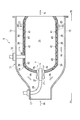
- FIG. 1 is a conceptual diagram of an aircraft gas turbine engine according to an embodiment of the present invention.
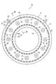
- FIG. 2 is a front sectional view of a combustor for a gas turbine engine according to an embodiment of the present invention.
- FIG. 3 is an enlarged cross-sectional view taken along line III-III in FIG. 4A is a cross-sectional view showing the main part of the liner outer wall or the liner inner wall, and
- FIG. 4B is a view showing a part of the state in which the combustor liner is developed on a plane.
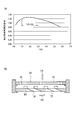
- FIG. 5 (a) is a diagram showing the relationship between the ratio (H / D) of the height dimension of the heat transfer pin and the equivalent diameter of the impingement cooling hole and the effective heat transfer area expansion rate, and FIG. It is a figure explaining a cooling performance test.
- FF indicates a forward direction (upstream direction as viewed from the mainstream flow)
- FR indicates a rearward direction (downstream direction as viewed from the mainstream flow).
- the gas turbine engine (gas turbine) according to the present embodiment is used for, for example, an aircraft or a generator.
- a gas turbine engine (gas turbine) 1 according to this embodiment includes a compressor 3.
- the compressor 3 compresses the air A taken into the gas turbine engine 1 to generate compressed air PA.
- a turbine 5 is connected to the compressor 3 via a turbine shaft (rotary shaft) 7.
- the turbine 5 is driven by the expanding combustion gas G, and drives the compressor 3 via the turbine shaft 7 simultaneously with this driving.
- a combustor 9 is provided between the compressor 3 and the turbine 5.
- the combustor 9 burns the fuel F in the compressed air PA sent from the compressor 3, generates combustion gas G, and discharges it to the turbine 5 side.
- the combustor 9 is, for example, an annular combustor.
- the combustor 9 includes an annular (hollow annular) combustor case 11.
- the combustor case 11 includes an annular outer case 13 and an annular inner case 15 provided inside the outer case 13. Furthermore, an annular inlet 17 for introducing the compressed air PA from the compressor 3 into the combustor case 11 is formed at the front portion of the combustor case 11.
- annular (hollow annular) combustor liner 19 is provided in the combustor case 11.
- the combustor liner 19 includes an annular outer liner 21 and an annular inner liner 23 provided inside the outer liner 21.
- An annular combustion chamber 25 for burning the fuel F is formed in the combustor liner 19.
- an annular combustion chamber 25 is formed between the outer liner 21 and the inner liner 23.
- the outer case 13, the inner case 15, the outer liner 21, and the inner liner 23 are all provided concentrically.
- a plurality of fuel nozzles 27 for injecting fuel F into the combustion chamber 25 are provided in the front portion of the combustor liner 19 at intervals in the circumferential direction.
- a fuel pipe 29 for supplying the fuel F is connected to each fuel nozzle 27.
- Each fuel pipe 29 protrudes outward from the combustor case 11.
- a swirler 31 is provided on the periphery of each fuel nozzle 27 at the front portion of the combustor liner 19.
- the swirler 31 functions as an introduction member that introduces the compressed air PA into the combustion chamber 25 as a swirling flow.
- the combustor case 11 is provided with a plurality of spark plugs 33 that ignite (ignite) the fuel F. The tip of each spark plug 33 protrudes inside the combustor case 11 (inside the combustion chamber 25).
- the outer liner 21 and the inner liner 23 have a double wall structure including a liner outer wall 35 and a liner inner wall 37, respectively.
- the liner outer wall 35 is formed with a plurality of impingement cooling holes 39 through which a part of the compressed air PA is jetted as cooling air CA toward the outer surface (outer wall surface) of the liner inner wall 37.
- a center line 39 c of the cooling hole 39 is parallel to the thickness direction TP of the liner outer wall 35.
- the liner inner wall 37 is formed with a plurality of effusion cooling holes 41 through which the cooling air CA is ejected along the inner surface (inner wall surface) of the liner inner wall 37, and the center line of each effusion cooling hole 41 (
- the central axis 41c is inclined with respect to the thickness direction TP of the liner inner wall 37 so that the outlet of the effusion cooling hole 41 is located downstream of the inlet.
- the diameter of the cross section perpendicular to the center line 41c of the effusion cooling hole 41 (or the equivalent diameter of the effusion cooling hole 41) and the diameter of the cross section perpendicular to the center line (central axis) 39c of the impingement cooling hole 39 (or impingement cooling).
- the equivalent diameter of the holes 39 is arbitrarily set according to the design.
- the equivalent diameter of a hole means the diameter of the cross section when the cross section perpendicular to the center line of the hole is circular, and the hydraulic diameter (4 ⁇ cross sectional area / circumference) when the cross section is not circular. (Long).
- the ratio (Z / D) between the distance Z between the inner surface of the liner outer wall 35 and the outer surface of the liner inner wall 37 and the equivalent diameter D of the impingement cooling hole 39 is set so that the impingement cooling performance is sufficiently exhibited. It is set to 0-5.0.
- a plurality of heat transfer pins (radiation pins) 43 are formed on the outer surface of the liner inner wall 37.
- the front end surface of each heat transfer pin 43 is not in contact with the inner surface of the liner outer wall 35.
- the ratio (H / D) between the height dimension H of the heat transfer pin 43 and the equivalent diameter D of the impingement cooling hole is set to 1.0 to 3.0.
- the reason why the ratio (H / D) is set to 1.0 or more is that when the ratio (H / D) is set to less than 1.0, the heat radiation action by the heat transfer pins 43 is not sufficiently exhibited.
- the ratio (H / D) is set to 3.0 or less, even if the ratio (H / D) is set to a value exceeding 3.0, the heat dissipation action by the heat transfer pin 43 is not improved. This is because the weight of the combustor liner 19 is increased.
- the cross-sectional shape of the heat transfer pin 43 is not limited to the quadrangle shown in FIG. 4 and can be set to an arbitrary shape.
- Compressed air PA sent from the compressor 3 is introduced into the combustor case 11 from the introduction port 17, and then introduced as a swirling flow from the swirler 31 into the combustion chamber 25.
- the fuel F is injected into the combustion chamber 25 from the plurality of fuel nozzles 27, and the fuel F is ignited by the spark plug 33.
- the fuel F burns in the compressed air PA in the combustion chamber 25 and combustion gas G is generated.
- the combustion gas G is discharged to the turbine 5 side, and the operation of the gas turbine engine 1 is continued.
- the compressed air PA flows between the inner surface of the combustor case 11 and the outer surface of the combustor liner 19.
- the compressed air PA is ejected from the plurality of impingement cooling holes 39 toward the outer surface of the liner inner wall 37.
- the ejected cooling air CA collides with the outer surface of the liner inner wall 37 and impinges the liner inner wall 37.
- the cooling air CA that has contributed to impingement cooling is ejected from the plurality of effusion cooling holes 41 along the inner surface of the liner inner wall 37. Accordingly, the cooling air CA flows along the inner surface of the liner inner wall 37 and performs effusion cooling on the liner inner wall 37.
- each heat transfer pin 43 is not in contact with the inner surface of the liner outer wall 35, and the ratio of the height dimension H of the heat transfer pin 43 to the equivalent diameter D of the impingement cooling hole 39 (H / D) is set to 1.0 to 3.0. Therefore, when the above-described new knowledge is applied, the increase in the weight of the combustor liner 19 is suppressed and the temperature of the combustor liner 19 is increased (in particular, the liner inner wall 37). The cooling efficiency of the combustor liner 19 can be sufficiently increased.
- the present invention is not limited to the description of the above-described embodiment.
- the technical idea applied to the gas turbine engine 1 is applied to a power generation gas turbine engine (not shown). It can be implemented in an embodiment. Further, the scope of rights encompassed by the present invention is not limited to these embodiments.
- the cooling performance of the combustor liner can be evaluated from the effective heat transfer area expansion rate.
- the effective heat transfer area expansion rate is the product of the cooling side heat transfer area and the average heat transfer coefficient when there is no heat transfer pin, and the cooling side heat transfer area and the average heat transfer coefficient when there is a heat transfer pin. It is the product ratio. When the effective heat transfer area expansion rate is high, the cooling efficiency is also increased.
- Fig. 5 (a) shows the relationship of the ratio (H / D) to the effective heat transfer area expansion rate. Note that H is the height dimension of the heat transfer pin described above, and D is the equivalent diameter of the impingement cooling hole described above.
- the relationship of FIG. 5A was obtained by correcting the analysis result obtained by CFD (Computational Fluid Dynamics) analysis with the result of the cooling performance test.
- CFD Computer Fluid Dynamics
- a test product 59 simulating the combustor liner 19 is used, the hot gas HG flows on the liner inner wall 77 side, and the test product 59 cools on the liner outer wall 75 side. The surface temperature on the liner inner wall 77 side of the test article 19 when the air CA was flowing was detected.
- a plurality of impingement cooling holes 79 are formed in the liner outer wall 75, and a plurality of effusion cooling holes 81 are formed in the liner inner wall 77. Further, a plurality of heat transfer pins 83 are formed on the outer surface of the liner inner wall 77. The front end surface of each heat transfer pin 83 is not in contact with the inner surface of the liner outer wall 75. That is, the impingement cooling hole 79, the effusion cooling hole 81, and the heat transfer pin 83 in FIG. 5B correspond to the impingement cooling hole 39, the effusion cooling hole 41, and the heat transfer pin 43 in FIG. 4A, respectively.
- the effective heat transfer area expansion ratio is obtained when the ratio (H / D) of the heat transfer pin height dimension H to the impingement cooling hole equivalent diameter D is 1.0 to 3.0. It turned out to be high.
- the ratio (H / D) between the height dimension H of the heat transfer pin and the equivalent diameter D of the impingement cooling hole is 1 in a state where the tip surface of the heat transfer pin is not in contact with the inner surface of the liner outer wall. It was found that the cooling performance of the combustor liner is sufficiently increased by setting the value to 0.0 or more. It is also found that the cooling performance of the combustor liner is not improved even if the ratio (H / D) of the heat transfer pin height dimension H to the impingement cooling hole equivalent diameter D exceeds 3.0. It was.
Abstract
Description
Claims (4)
- ガスタービンエンジンに用いられ、圧縮空気中で燃料を燃焼させて、燃焼ガスを生成するガスタービンエンジン用燃焼器において、
燃焼器ケースと、
前記燃焼器ケースの内側に設けられ、内側に前記燃料を燃焼させるための燃焼室が形成された燃焼器ライナと、を具備し、
前記燃焼器ライナは、ライナ外壁とライナ内壁を有した二重壁構造に構成され、前記ライナ外壁に圧縮空気の一部を冷却空気として前記ライナ内壁の外表面に向かって噴き出すための複数のインピンジ冷却孔が貫通して形成され、前記ライナ内壁に冷却空気を前記ライナ内壁の内表面に沿って噴き出すための複数のエフュージョン冷却孔が貫通して形成され、前記ライナ内壁の外表面に複数の伝熱ピンが形成され、各伝熱ピンの先端面が前記ライナ外壁の内表面に対して非接触であって、前記伝熱ピンの高さ寸法と前記インピンジ冷却孔の等価直径との比が1.0~3.0に設定されていることを特徴とするガスタービンエンジン用燃焼器。 - 前記ライナ外壁の内表面と前記ライナ内壁の外表面の間隔寸法と前記インピンジ冷却孔の等価直径との比が1.0~5.0に設定されていることを特徴とする請求項1に記載のガスタービンエンジン用燃焼器。
- 前記燃焼器ライナを平面に展開した状態において、各インピンジ冷却孔の出口部、各エフュージョン冷却孔の入口部、各伝熱ピンがそれぞれ異なる位置に配置されていることを特徴とする請求項1又は請求項2に記載のガスタービンエンジン用燃焼器。
- 請求項1から請求項3のうちのいずれかの請求項に記載のガスタービンエンジン用燃焼器を具備したことを特徴とするガスタービン。
Priority Applications (5)
| Application Number | Priority Date | Filing Date | Title |
|---|---|---|---|
| CA2831281A CA2831281C (en) | 2011-03-31 | 2012-03-29 | Combustor for gas turbine engine and gas turbine |
| KR1020137027656A KR101591398B1 (ko) | 2011-03-31 | 2012-03-29 | 가스 터빈 엔진용 연소기 및 가스 터빈 |
| CN201280015923.3A CN103534531B (zh) | 2011-03-31 | 2012-03-29 | 燃气轮机发动机用燃烧器及燃气轮机 |
| EP12764873.1A EP2693122A4 (en) | 2011-03-31 | 2012-03-29 | BURNER FOR A GAS TURBINE AND GAS TURBINE |
| US14/040,025 US20140020393A1 (en) | 2011-03-31 | 2013-09-27 | Combustor for gas turbine engine and gas turbine |
Applications Claiming Priority (2)
| Application Number | Priority Date | Filing Date | Title |
|---|---|---|---|
| JP2011-078486 | 2011-03-31 | ||
| JP2011078486A JP5696566B2 (ja) | 2011-03-31 | 2011-03-31 | ガスタービンエンジン用燃焼器及びガスタービンエンジン |
Related Child Applications (1)
| Application Number | Title | Priority Date | Filing Date |
|---|---|---|---|
| US14/040,025 Continuation US20140020393A1 (en) | 2011-03-31 | 2013-09-27 | Combustor for gas turbine engine and gas turbine |
Publications (1)
| Publication Number | Publication Date |
|---|---|
| WO2012133630A1 true WO2012133630A1 (ja) | 2012-10-04 |
Family
ID=46931332
Family Applications (1)
| Application Number | Title | Priority Date | Filing Date |
|---|---|---|---|
| PCT/JP2012/058330 WO2012133630A1 (ja) | 2011-03-31 | 2012-03-29 | ガスタービンエンジン用燃焼器及びガスタービン |
Country Status (7)
| Country | Link |
|---|---|
| US (1) | US20140020393A1 (ja) |
| EP (1) | EP2693122A4 (ja) |
| JP (1) | JP5696566B2 (ja) |
| KR (1) | KR101591398B1 (ja) |
| CN (1) | CN103534531B (ja) |
| CA (1) | CA2831281C (ja) |
| WO (1) | WO2012133630A1 (ja) |
Cited By (4)
| Publication number | Priority date | Publication date | Assignee | Title |
|---|---|---|---|---|
| EP2833071A3 (en) * | 2013-08-02 | 2015-02-25 | Pratt & Whitney Canada Corp. | Methods and apparatus for inspecting cooling holes |
| WO2015039074A1 (en) | 2013-09-16 | 2015-03-19 | United Technologies Corporation | Controlled variation of pressure drop through effusion cooling in a double walled combustor of a gas turbine engine |
| EP3453970A3 (en) * | 2017-09-06 | 2019-03-20 | United Technologies Corporation | Float wall combustor panels having heat transfer augmentation |
| US10352566B2 (en) | 2013-06-14 | 2019-07-16 | United Technologies Corporation | Gas turbine engine combustor liner panel |
Families Citing this family (30)
| Publication number | Priority date | Publication date | Assignee | Title |
|---|---|---|---|---|
| JP5834876B2 (ja) | 2011-12-15 | 2015-12-24 | 株式会社Ihi | インピンジ冷却機構、タービン翼及び燃焼器 |
| US9638057B2 (en) * | 2013-03-14 | 2017-05-02 | Rolls-Royce North American Technologies, Inc. | Augmented cooling system |
| US10670268B2 (en) * | 2013-05-23 | 2020-06-02 | Raytheon Technologies Corporation | Gas turbine engine combustor liner panel |
| WO2015050592A2 (en) * | 2013-06-14 | 2015-04-09 | United Technologies Corporation | Gas turbine engine combustor liner panel |
| JP6178640B2 (ja) * | 2013-06-28 | 2017-08-09 | 三菱日立パワーシステムズ株式会社 | ガスタービン用燃焼器 |
| EP3077641B1 (en) * | 2013-12-06 | 2020-02-12 | United Technologies Corporation | Cooling an igniter aperture body of a combustor wall |
| US9625158B2 (en) * | 2014-02-18 | 2017-04-18 | Dresser-Rand Company | Gas turbine combustion acoustic damping system |
| US10689988B2 (en) * | 2014-06-12 | 2020-06-23 | Raytheon Technologies Corporation | Disk lug impingement for gas turbine engine airfoil |
| JP6282184B2 (ja) | 2014-06-19 | 2018-02-21 | 三菱日立パワーシステムズ株式会社 | 伝熱装置及びそれを備えたガスタービン燃焼器 |
| CN105222158B (zh) * | 2014-06-30 | 2018-04-13 | 中国航发商用航空发动机有限责任公司 | 浮动瓦块以及燃烧室火焰筒 |
| GB201412460D0 (en) * | 2014-07-14 | 2014-08-27 | Rolls Royce Plc | An Annular Combustion Chamber Wall Arrangement |
| US10598382B2 (en) * | 2014-11-07 | 2020-03-24 | United Technologies Corporation | Impingement film-cooled floatwall with backside feature |
| US10670272B2 (en) * | 2014-12-11 | 2020-06-02 | Raytheon Technologies Corporation | Fuel injector guide(s) for a turbine engine combustor |
| US10746403B2 (en) * | 2014-12-12 | 2020-08-18 | Raytheon Technologies Corporation | Cooled wall assembly for a combustor and method of design |
| CN104566458A (zh) * | 2014-12-25 | 2015-04-29 | 北京华清燃气轮机与煤气化联合循环工程技术有限公司 | 一种带有冷却结构的燃气轮机燃烧室过渡段 |
| CN104896514A (zh) * | 2015-05-13 | 2015-09-09 | 广东电网有限责任公司电力科学研究院 | 燃气轮机主燃烧室防振隔热壁 |
| CA2933884A1 (en) * | 2015-06-30 | 2016-12-30 | Rolls-Royce Corporation | Combustor tile |
| US10260751B2 (en) * | 2015-09-28 | 2019-04-16 | Pratt & Whitney Canada Corp. | Single skin combustor with heat transfer enhancement |
| GB201518345D0 (en) * | 2015-10-16 | 2015-12-02 | Rolls Royce | Combustor for a gas turbine engine |
| US10495309B2 (en) | 2016-02-12 | 2019-12-03 | General Electric Company | Surface contouring of a flowpath wall of a gas turbine engine |
| US10876730B2 (en) | 2016-02-25 | 2020-12-29 | Pratt & Whitney Canada Corp. | Combustor primary zone cooling flow scheme |
| NO342066B1 (en) * | 2016-06-03 | 2018-03-19 | Vetco Gray Scandinavia As | Modular stackable compressor with gas bearings and system for raising the pressure in production gas |
| US10830433B2 (en) | 2016-11-10 | 2020-11-10 | Raytheon Technologies Corporation | Axial non-linear interface for combustor liner panels in a gas turbine combustor |
| US10655853B2 (en) | 2016-11-10 | 2020-05-19 | United Technologies Corporation | Combustor liner panel with non-linear circumferential edge for a gas turbine engine combustor |
| US10935236B2 (en) * | 2016-11-10 | 2021-03-02 | Raytheon Technologies Corporation | Non-planar combustor liner panel for a gas turbine engine combustor |
| US10935235B2 (en) * | 2016-11-10 | 2021-03-02 | Raytheon Technologies Corporation | Non-planar combustor liner panel for a gas turbine engine combustor |
| IT201700012500A1 (it) * | 2017-02-06 | 2018-08-06 | Nuovo Pignone Tecnologie Srl | Turbomacchina e metodo di funzionamento di una turbomacchina |
| US20190040796A1 (en) * | 2017-08-03 | 2019-02-07 | United Technologies Corporation | Gas turbine engine cooling arrangement |
| JP6908472B2 (ja) * | 2017-08-31 | 2021-07-28 | 三菱重工コンプレッサ株式会社 | 遠心圧縮機 |
| US11306918B2 (en) * | 2018-11-02 | 2022-04-19 | Chromalloy Gas Turbine Llc | Turbulator geometry for a combustion liner |
Citations (5)
| Publication number | Priority date | Publication date | Assignee | Title |
|---|---|---|---|---|
| JPS61231330A (ja) * | 1985-04-05 | 1986-10-15 | Agency Of Ind Science & Technol | ガスタ−ビンの燃焼器 |
| JPH031015A (ja) * | 1989-05-26 | 1991-01-07 | Toshiba Corp | ガスタービン燃焼器 |
| JPH1162504A (ja) * | 1997-08-13 | 1999-03-05 | Ishikawajima Harima Heavy Ind Co Ltd | タービン翼の二重壁冷却構造 |
| JP2009162119A (ja) * | 2008-01-08 | 2009-07-23 | Ihi Corp | タービン翼の冷却構造 |
| JP2010043643A (ja) | 2008-08-15 | 2010-02-25 | General Electric Co <Ge> | インピンジメント及びエフュージョン冷却式燃焼器部品 |
Family Cites Families (9)
| Publication number | Priority date | Publication date | Assignee | Title |
|---|---|---|---|---|
| CN1012444B (zh) * | 1986-08-07 | 1991-04-24 | 通用电气公司 | 冲击冷却过渡进气道 |
| US5353865A (en) * | 1992-03-30 | 1994-10-11 | General Electric Company | Enhanced impingement cooled components |
| GB9926257D0 (en) * | 1999-11-06 | 2000-01-12 | Rolls Royce Plc | Wall elements for gas turbine engine combustors |
| US20020066273A1 (en) * | 2000-12-04 | 2002-06-06 | Mitsubishi Heavy Industries, Ltd. | Plate fin and combustor using the plate fin |
| US6964170B2 (en) * | 2003-04-28 | 2005-11-15 | Pratt & Whitney Canada Corp. | Noise reducing combustor |
| DE102007018061A1 (de) * | 2007-04-17 | 2008-10-23 | Rolls-Royce Deutschland Ltd & Co Kg | Gasturbinenbrennkammerwand |
| US20100170257A1 (en) * | 2009-01-08 | 2010-07-08 | General Electric Company | Cooling a one-piece can combustor and related method |
| US20100186415A1 (en) * | 2009-01-23 | 2010-07-29 | General Electric Company | Turbulated aft-end liner assembly and related cooling method |
| US8307657B2 (en) | 2009-03-10 | 2012-11-13 | General Electric Company | Combustor liner cooling system |
-
2011
- 2011-03-31 JP JP2011078486A patent/JP5696566B2/ja active Active
-
2012
- 2012-03-29 EP EP12764873.1A patent/EP2693122A4/en not_active Ceased
- 2012-03-29 CA CA2831281A patent/CA2831281C/en active Active
- 2012-03-29 CN CN201280015923.3A patent/CN103534531B/zh active Active
- 2012-03-29 WO PCT/JP2012/058330 patent/WO2012133630A1/ja active Application Filing
- 2012-03-29 KR KR1020137027656A patent/KR101591398B1/ko active IP Right Grant
-
2013
- 2013-09-27 US US14/040,025 patent/US20140020393A1/en not_active Abandoned
Patent Citations (5)
| Publication number | Priority date | Publication date | Assignee | Title |
|---|---|---|---|---|
| JPS61231330A (ja) * | 1985-04-05 | 1986-10-15 | Agency Of Ind Science & Technol | ガスタ−ビンの燃焼器 |
| JPH031015A (ja) * | 1989-05-26 | 1991-01-07 | Toshiba Corp | ガスタービン燃焼器 |
| JPH1162504A (ja) * | 1997-08-13 | 1999-03-05 | Ishikawajima Harima Heavy Ind Co Ltd | タービン翼の二重壁冷却構造 |
| JP2009162119A (ja) * | 2008-01-08 | 2009-07-23 | Ihi Corp | タービン翼の冷却構造 |
| JP2010043643A (ja) | 2008-08-15 | 2010-02-25 | General Electric Co <Ge> | インピンジメント及びエフュージョン冷却式燃焼器部品 |
Non-Patent Citations (1)
| Title |
|---|
| See also references of EP2693122A4 |
Cited By (7)
| Publication number | Priority date | Publication date | Assignee | Title |
|---|---|---|---|---|
| US10352566B2 (en) | 2013-06-14 | 2019-07-16 | United Technologies Corporation | Gas turbine engine combustor liner panel |
| EP3008386B1 (en) * | 2013-06-14 | 2020-06-17 | United Technologies Corporation | Gas turbine engine combustor liner panel |
| EP2833071A3 (en) * | 2013-08-02 | 2015-02-25 | Pratt & Whitney Canada Corp. | Methods and apparatus for inspecting cooling holes |
| US9182318B2 (en) | 2013-08-02 | 2015-11-10 | Pratt & Whitney Canada Corp. | Methods and apparatus for inspecting cooling holes |
| WO2015039074A1 (en) | 2013-09-16 | 2015-03-19 | United Technologies Corporation | Controlled variation of pressure drop through effusion cooling in a double walled combustor of a gas turbine engine |
| EP3047128A4 (en) * | 2013-09-16 | 2016-08-24 | United Technologies Corp | CONTROLLED VARIATION OF PRESSURE WASTE BY EFFUSION COOLING IN A DOUBLE-WALL COMBUSTION CHAMBER OF A GAS TURBINE ENGINE |
| EP3453970A3 (en) * | 2017-09-06 | 2019-03-20 | United Technologies Corporation | Float wall combustor panels having heat transfer augmentation |
Also Published As
| Publication number | Publication date |
|---|---|
| EP2693122A1 (en) | 2014-02-05 |
| CA2831281A1 (en) | 2012-10-04 |
| CN103534531B (zh) | 2015-06-03 |
| JP5696566B2 (ja) | 2015-04-08 |
| KR101591398B1 (ko) | 2016-02-03 |
| US20140020393A1 (en) | 2014-01-23 |
| CN103534531A (zh) | 2014-01-22 |
| JP2012211749A (ja) | 2012-11-01 |
| CA2831281C (en) | 2015-12-29 |
| KR20130132654A (ko) | 2013-12-04 |
| EP2693122A4 (en) | 2014-10-22 |
Similar Documents
| Publication | Publication Date | Title |
|---|---|---|
| WO2012133630A1 (ja) | ガスタービンエンジン用燃焼器及びガスタービン | |
| KR102622706B1 (ko) | 연소기용 토치 점화기 | |
| JP5860620B2 (ja) | ターボ機械用噴射ノズル | |
| JP4902208B2 (ja) | 燃焼器用ベンチュリ | |
| US8943832B2 (en) | Fuel nozzle assembly for use in turbine engines and methods of assembling same | |
| JP2012017971A5 (ja) | ||
| JP2010223577A (ja) | スワーラ、少なくとも1つのスワーラを備えたバーナにおける逆火の防止方法およびバーナ | |
| JP6086860B2 (ja) | ノズル、燃焼器、及びガスタービン | |
| JP6086391B2 (ja) | ガス・タービン・エンジンで使用するための段階的で接線方向の燃料空気ノズルを備えた環状筒型燃焼器 | |
| JP2013148338A (ja) | インピンジメントスリーブ孔及びタービュレータを備えた燃焼器組立体 | |
| KR20150020135A (ko) | 버너 장치 및 버너 장치를 작동하기 위한 방법 | |
| JP6086371B2 (ja) | ガス・タービン・エンジン用環状筒型燃焼器における燃焼反応物混合方法 | |
| JP2014122784A (ja) | 燃焼器に燃料を供給するためのシステム | |
| JP2013231575A (ja) | 燃焼器 | |
| JP2010216481A (ja) | バーナーを通過する高温ガス流を部分的に冷却するためのガスタービン用バーナー及び方法 | |
| JP2013535651A (ja) | ガスタービン燃焼室 | |
| US20110302904A1 (en) | Pulsed Detonation Cleaning Device with Multiple Folded Flow Paths | |
| EP2515041B1 (en) | Fuel Nozzle And Method For Operating A Combustor | |
| US20130219897A1 (en) | Combustor and gas turbine | |
| US20120192545A1 (en) | Pulse Detonation Combustor Nozzles | |
| JP2007064625A5 (ja) | ||
| JP6092007B2 (ja) | ガスタービン燃焼器 | |
| KR101579122B1 (ko) | 가스터빈의 연소기 및 이를 포함하는 가스터빈 및 이의 냉각방법 | |
| JP6138231B2 (ja) | 燃焼装置 | |
| JP5991025B2 (ja) | バーナ及びガスタービン燃焼器 |
Legal Events
| Date | Code | Title | Description |
|---|---|---|---|
| 121 | Ep: the epo has been informed by wipo that ep was designated in this application |
Ref document number: 12764873 Country of ref document: EP Kind code of ref document: A1 |
|
| ENP | Entry into the national phase |
Ref document number: 2831281 Country of ref document: CA |
|
| NENP | Non-entry into the national phase |
Ref country code: DE |
|
| ENP | Entry into the national phase |
Ref document number: 20137027656 Country of ref document: KR Kind code of ref document: A |
|
| WWE | Wipo information: entry into national phase |
Ref document number: 2012764873 Country of ref document: EP |