EP1648779B1 - Procede et machine de thermoretraction de manchons thermoretractables - Google Patents
Procede et machine de thermoretraction de manchons thermoretractables Download PDFInfo
- Publication number
- EP1648779B1 EP1648779B1 EP04767727A EP04767727A EP1648779B1 EP 1648779 B1 EP1648779 B1 EP 1648779B1 EP 04767727 A EP04767727 A EP 04767727A EP 04767727 A EP04767727 A EP 04767727A EP 1648779 B1 EP1648779 B1 EP 1648779B1
- Authority
- EP
- European Patent Office
- Prior art keywords
- article
- chamber
- sleeve
- support
- machine
- Prior art date
- Legal status (The legal status is an assumption and is not a legal conclusion. Google has not performed a legal analysis and makes no representation as to the accuracy of the status listed.)
- Expired - Lifetime
Links
Images


Classifications
-
- B—PERFORMING OPERATIONS; TRANSPORTING
- B65—CONVEYING; PACKING; STORING; HANDLING THIN OR FILAMENTARY MATERIAL
- B65B—MACHINES, APPARATUS OR DEVICES FOR, OR METHODS OF, PACKAGING ARTICLES OR MATERIALS; UNPACKING
- B65B53/00—Shrinking wrappers, containers, or container covers during or after packaging
- B65B53/02—Shrinking wrappers, containers, or container covers during or after packaging by heat
- B65B53/06—Shrinking wrappers, containers, or container covers during or after packaging by heat supplied by gases, e.g. hot-air jets
- B65B53/066—Mobile frames, hoods, posts or the like
-
- B—PERFORMING OPERATIONS; TRANSPORTING
- B65—CONVEYING; PACKING; STORING; HANDLING THIN OR FILAMENTARY MATERIAL
- B65B—MACHINES, APPARATUS OR DEVICES FOR, OR METHODS OF, PACKAGING ARTICLES OR MATERIALS; UNPACKING
- B65B53/00—Shrinking wrappers, containers, or container covers during or after packaging
- B65B53/02—Shrinking wrappers, containers, or container covers during or after packaging by heat
Definitions
- the present invention relates to the field of heat shrink sleeves made from a heat-shrinkable plastic film and strung individually on objects such as for example bottles.
- the same object can be conditioned at extremely variable temperatures depending on the point of sale.
- These extremely variable temperatures of the wall of the object in fact substantially modify the conditions for retraction of a heat-shrinkable sleeve on said objects.
- the sizing of the object, in particular the sectional variations of said objects will also have a great importance on the retraction conditions insofar as the retraction call can vary considerably from the top to the bottom of the object.
- the nature (PET, PS, recyclable or not) and the thickness of the film constituting the sleeve to retract on the object can also vary, and also change the conditions of retraction.
- a retraction technique should be available which allows for implementation under widely varying conditions, particularly for the temperature at which the articles are packaged before being coated with a heat-shrinkable sleeve.
- the aim of the invention is to propose a method and a heat-shrinking machine that is both simple to implement and capable of coping with the extremely variable conditions encountered for the objects and the associated heat shrink sleeves, in particular at the temperature level. concerned, which are known to play a vital role in controlling the retraction of the sleeves on an object to have a perfect state after the retraction is complete.
- the parameters of temperatures, speeds of movement of the support and time are controlled according to the object concerned and the constituent film of the sleeve concerned.
- the parameters are controlled by a programmable controller responsible for managing the sequences of operations implemented in said method.
- the blowing of air into the shrink chamber is also used periodically to maintain the desired heat in the preheat chamber.
- the displacement of the mobile support during the transfer of the object into the preheating chamber and the passage of said object in the retraction chamber is performed in the same vertical direction.
- the support is rotated at a controlled rate on itself about a vertical axis before and during the passage of the object with its sleeve in the retraction chamber.
- the axial displacement of the mobile support is carried out at variable speed to optimize the duration of a complete cycle.
- the object support is mounted so that it can also rotate about itself about its vertical central axis.
- the object support is arranged to wedge the object supported on the vertical central axis, and possibly also to protect all or part of the lower zone of said object.
- the radiant chimney constituting the preheating chamber has a wall thickness and / or a cross section that is variable in case of significantly different shrinkage rates between the lower and upper zones of the sleeve to retract on the object.
- the retraction chamber is of annular structure, and it is wedged on the vertical central axis of the object support.
- the annular retraction chamber has a cylindrical inner wall having at least one slot for the outlet of the diffused hot air.
- the inner wall of the annular shrink chamber has a plurality of slits that are inclined relative to the horizontal, and the components for diffusing the blown air are constituted by metal wool ribbons.
- the machine comprises an elevator which are secured on the one hand the object support and on the other hand a motor driving in rotation on itself of said object carrier, and a motor actuating said elevator for to ensure the vertical axial displacement of the object support, and the machine of said machine is connected to the two aforementioned engines as well as to the hot air blowing assembly associated with the retraction chamber, in order to drive different temperature, speed and time parameters.
- the automaton is programmable in particular to take into account the dimensions of the object concerned and the temperature of said object during the introduction into said machine, as well as the nature and thickness of the constituent film of the sleeve concerned. .
- the machine comprises a protective cowling with a window allowing a manual introduction and removal of the object without risk of touching hot parts of said machine.
- a heat-shrinking machine which is intended to implement a method of heat shrink sleeves made from a heat-shrinkable plastic film and strung individually on objects such as bottles.
- bottles which represent certainly a preferred field of application
- the invention is in no way limited to such a type of object, and may equally well apply to other types of containers or other types of objects intended to be coated by a heat-shrinkable sleeve carrying a visual desired by the consumer.
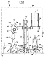
- heat-shrinking machine 100 which is intended to allow heat-shrinking of sleeves made from a heat-shrinkable plastic film and threaded individually onto objects such as bottles.
- a bottle 10 whose associated sleeve, which is threaded on said bottle, is referenced 11.
- the machine 100 comprises a fixed frame 101, here made in the form of a support plate, on which various components are arranged. It is preferably provided a protective cowl allowing a manual introduction and removal of the object 10 without the risk of touching hot parts of the machine 100. Diagrammatically shown in phantom such a protective cover 200, which has a window 201 giving access to the area of an object support on which the consumer puts the unitary object 10 with its sleeve 11 threaded on said object, then retrieves the assembly after retraction of said sleeve on said object.
- the fixed frame 101 carries a vertical column 102 which constitutes a guide element for an elevator slider 103 which is associated with said small column 102.
- the elevator slider 103 is equipped with a cantilevered assembly housing 104 above which is installed an object support 105.
- a motor 106 is part of this vertically displaceable assembly, and allows to ensure the rotation about itself, about a central vertical axis X, of the object support 105.
- the motor 106 will preferably be electric, but may in variant be pneumatically operated.
- a connector 106.1 is associated with the drive motor 106, and it is possible to distinguish on the figure 2 the connecting cable 106.2 leading to a general box 150 which is none other than a programmable controller responsible for managing the sequences of operations implemented in the heat shrink process of the invention.
- the aforementioned movable element comprising in particular the object support 105 with its associated motor 106 can thus move in a vertical direction, being guided in its movements by the column 102 on which slides the elevator carriage 103.
- the object support 105 is thus mounted to move relative to the fixed frame 101 along the vertical central axis X, and this between a low position of installation or removal of object (position illustrated on the figure 1 ) and a high position in which the object 10 is entirely contained in a preheating chamber 140 surmounting an annular retraction chamber 130.
- a preheating chamber 140 surmounting an annular retraction chamber 130.
- the object support 105 is thus mounted in this case to be able to rotate about itself about its vertical central axis X, this rotation appearing in fact interesting during the retraction step properly. said sleeve on the object.
- the elevator slider 103 is extended by a bracket 107 which is connected to a nut 108 which is engaged with the teeth of a threaded rod 109 of vertical axis, interposed between the frame 101 and an upper plate 110 connecting it to the balancer 102, to ensure a perfect verticality of said threaded rod 109.
- the threaded rod 109 is however not integral with the frame 101 and the wafer 110, but can rotate about its vertical axis, and this through means of associated drive which is constituted by a motor 116 whose output shaft 117 is connected to a gear housing 115 in engagement with the threaded rod 109.
- the motor 116 will preferably be electrical, but may alternatively be pneumatically operated .
- the electric motor 116 is connected by a cable 116.2 to the general machine of the machine 150.
- the axial displacement of the moving element is ensured between two precise levels, namely a lower level which corresponds to the position of installation or removal of object, and a higher level which corresponds to the housing of said object within the preheating chamber 140.
- end-of-stroke sensors will be provided associated with these two precise positions, with which, for example, the elevator slide 103 engages.
- Each of these two sensors will of course be connected to the motor control 116. and to the general automaton 150 (the aforementioned sensors are of conventional use and have not been illustrated here).
- the object support 105 is arranged to wedge the object supported on the vertical central axis X, this with projecting pins 105.1. Indeed, during the rotation of the object support 105 around its central axis X, it is appropriate that the object, which will generally have a vertical central axis, is properly wedged on the vertical axis of rotation of the object support 105. There is also the presence of vertical fins projecting from the periphery of the object support 105, these fins being referenced 105.2.
- the object support 105 thus equipped is then able to protect all or part of the lower zone of the object placed on it thanks to these fins 105.2 which form heat shields when the base of the object is subjected a thermal field to retract the sleeve threaded on said object.
- the figure 1 also makes it possible to distinguish a vertical column 112 rigidly secured to the machine frame 101, in the upper part of which is mounted a hot air blowing assembly 120.
- This assembly 120 comprises a housing 121 inside which are housed an electric fan and an electrical resistance generating infrared radiation heat when said resistance is traversed by an electric current.
- This hot air blowing assembly 120 is connected by a cable 120.2 to the general machine of the machine 150, this for controlling the temperature of the hot air blown by the blowing assembly 120.
- the housing 121 is equipped on a side surface thereof with a start / stop button 122 and an operating indicator light 123, as well as a manual adjustment knob 124 for varying the electrical current flowing through the heating resistor , and as a result of modulating the temperature of the air blown by this assembly of hot air blowing 120.
- the output of the hot air blown is constituted by a cylindrical sleeve 125 rigidly fixed on the housing 121 of the assembly 120, which sleeve carries a nozzle 126 connected to a set here of annular structure forming a retraction chamber 130, which chamber is surmounted by a preheating chamber 140.
- the two chambers 130 and 140 are thus supported cantilevered by the pipes 125, 126 fixed to the housing 121 of the hot air blowing assembly 120.
- an auxiliary support may be provided, the structure of which, however, will be designed to withstand the temperatures concerned.
- the annular retraction chamber 130 is keyed on the vertical central axis X, and it is delimited above and below by flat rings 131 between which extend a cylindrical outer wall 132 and a cylindrical inner wall 133.
- the annular housing thus defined is supplied with hot air blown by the connection 135 to the nozzle 126.
- the hot air thus admitted into the annular space of the chamber 130 can only exit through openings here made in the form of slots 134.
- These slots 134 formed in the inner wall 133 of the annular retraction chamber 130, are in this case inclined relative to the horizontal, this to have a perfect quality of retraction of the lower part of the sleeve threaded onto the object.
- the cylindrical inner wall 133 thus delimits a central passage 139 whose axis coincides with the vertical central axis X of the aforementioned object support 105 and whose diameter is slightly greater than the external diameter of said object support 105.
- the preheating chamber 140 is constituted by a radiant chimney carried by the annular retraction chamber 130 being keyed on the X axis thereof.
- For the correct setting of the chimney 140 there are provided lower lugs 141 which are received in associated bores 138 formed on the upper ring 131 of the chamber 130. figure 3 the head of the bolts 137 solidarisant the two rings 131 defining the annular retraction chamber 130.
- the chimney 140 is radiant, that is to say that its upper orifice is of course opening, and that its inner surface produces heat only by radiation, to the exclusion of any presence of special heating elements.
- the chimney 140 will for example be made of stainless steel.
- the shrinkage rate of the associated sleeve will vary little. In this case, it can be satisfied with a chimney 140 of cylindrical shape, and of constant thickness from one end to the other of said chimney. However, in certain situations, the shrinkage rate may vary considerably over the height of the object, particularly from the top to the bottom of the object. In this case, he can it would be interesting to modulate accordingly the inner section of the chimney 140. It may be expected that the chimney 140 has a wall thickness and / or a cross section that is variable. Of course, it may be provided for the upper part of the chimney with conical tightening equipping a cylindrical main part (variant not shown here).
- this is a preliminary step of placing a unitary object 10 on the mobile support 105, a sleeve 11 being threaded onto said object.
- a sleeve 11 being threaded onto said object.
- This preheating step is essential for obtaining a perfect retraction of the sleeve on the object taking into account all the characteristics of the object concerned, in particular the temperature of said object and its dimensions, and also the constituent film of the heat shrinkable sleeve concerned, in particular the nature and thickness of said film.
- the temperature prevailing inside the preheating chamber 140 and the residence time of the object with its sleeve inside said chamber, are controlled by the general PLC 150.
- This PLC 150 will preferably be programmable to in particular to take into account the dimensions of the object 10 concerned and its temperature during installation in said machine, as well as the nature and thickness of the constituent film of the sleeve 11 concerned.
- the heating of the air blown by the air blowing assembly 120 is switched on so that the air escaping from the slots 134 of the annular retraction chamber 130 is at the temperature which has been previously chosen.
- the rotation of the object support 105 about its central axis X is engaged, as illustrated in b ').
- the next step then begins, consisting of a controlled speed pass of the object 10 with its sleeve 11 in the annular shrink chamber 130 at controlled temperature, in order to retract the sleeve 11 on the object 10.
- c) there is illustrated an intermediate situation of the passage of the object 10 in the annular retraction chamber 130, which explains that only the lower part of said sleeve is shown retracted on the object.
- the programmable logic controller 150 is responsible for managing all the sequences of operations implemented in the method, and thus controls all the parameters concerned.
- the figure 6 schematically illustrates the above control provided by the programmable controller 150.
- connection 106.2 With the connection 106.2, the motor 106 receives the speed (v) and operating time (t) instructions for each of the process steps. Similarly, the connection 116.2 sends the speed (v) and time (t) instructions to the motor 116 which ensures the axial displacement of the moving element.
- the connection 120.2 finally makes it possible to address the necessary instructions of current intensity (i) and time (t) to the hot air blowing unit 120 to obtain the desired temperature in the annular retraction chamber 130.
- the preconditioning phase After the laying on the dedicated base of the object with its sleeve threaded on said object, it ensures the stable maintenance with possible protection of the sensitive areas, and it is expected a rise of the mobile equipment to a speed of the order of five meters per second.
- a temperature of the order of 50 ° C. to 80 ° C. is provided inside the preheating chamber 140, with a holding time in said chamber ranging from about three to twenty seconds. It should be noted that the temperature will generally be significantly higher in the lower part of the chimney forming the preheating chamber 140 with, for example, a temperature of 75 ° C to 80 ° C at the bottom, and of the order of 40 ° C to 50 ° C in the upper part of said chimney.
- the retraction step itself, one provides blowing hot air at a temperature of 80 ° C to 90 ° C.
- the dedicated support is rotated at a speed of the order of 110 revolutions per minute, and the passage of the object in the annular retraction chamber 130 is preferably provided with a uniform speed of the order of five meters per minute. second. Once the object is completely out of the annular retraction chamber 130, it may be possible to provide an acceleration of the descent of the moving element, in order to reduce the overall cycle time.
- the installation and retraction of a single sleeve on an object may be provided to coat the same object of several superimposed sleeves, set up and retracted simultaneously or successively.
- the single sleeve may concern only a reduced area of the object, for example its upper part, central or low depending on the case.
Landscapes
- Engineering & Computer Science (AREA)
- Mechanical Engineering (AREA)
- Lining Or Joining Of Plastics Or The Like (AREA)
- Shaping By String And By Release Of Stress In Plastics And The Like (AREA)
- Extrusion Moulding Of Plastics Or The Like (AREA)
- Processing And Handling Of Plastics And Other Materials For Molding In General (AREA)
- Heating, Cooling, Or Curing Plastics Or The Like In General (AREA)
- Auxiliary Devices For And Details Of Packaging Control (AREA)
- Labeling Devices (AREA)
- Wrapping Of Specific Fragile Articles (AREA)
Priority Applications (3)
| Application Number | Priority Date | Filing Date | Title |
|---|---|---|---|
| PL04767727T PL1648779T3 (pl) | 2003-07-31 | 2004-07-19 | Sposób i maszyna do obkurczania termicznego rękawów termokurczliwych |
| SI200430817T SI1648779T1 (sl) | 2003-07-31 | 2004-07-19 | Postopek in stroj za toplotno skrčevanje toplotno skrčljivih ovojev |
| CY20081100845T CY1108609T1 (el) | 2003-07-31 | 2008-08-12 | Μεθοδος και μηχανη θερμοσυρρικνωσης θερμοσυρρικνουμενων περιβληματων |
Applications Claiming Priority (2)
| Application Number | Priority Date | Filing Date | Title |
|---|---|---|---|
| FR0309426A FR2858297B1 (fr) | 2003-07-31 | 2003-07-31 | Procede et machine de thermoretraction de manchons thermoretractables enfiles individuellement sur des objets tels que des bouteilles |
| PCT/FR2004/001904 WO2005021385A1 (fr) | 2003-07-31 | 2004-07-19 | Procede et machine de thermoretraction de manchons thermoretractables |
Publications (2)
| Publication Number | Publication Date |
|---|---|
| EP1648779A1 EP1648779A1 (fr) | 2006-04-26 |
| EP1648779B1 true EP1648779B1 (fr) | 2008-05-14 |
Family
ID=34043698
Family Applications (1)
| Application Number | Title | Priority Date | Filing Date |
|---|---|---|---|
| EP04767727A Expired - Lifetime EP1648779B1 (fr) | 2003-07-31 | 2004-07-19 | Procede et machine de thermoretraction de manchons thermoretractables |
Country Status (16)
| Country | Link |
|---|---|
| US (1) | US6925777B2 (pl) |
| EP (1) | EP1648779B1 (pl) |
| CN (1) | CN100450876C (pl) |
| AT (1) | ATE395264T1 (pl) |
| BR (1) | BRPI0412289A (pl) |
| CA (1) | CA2534147C (pl) |
| CY (1) | CY1108609T1 (pl) |
| DE (1) | DE602004013786D1 (pl) |
| DK (1) | DK1648779T3 (pl) |
| ES (1) | ES2305838T3 (pl) |
| FR (1) | FR2858297B1 (pl) |
| MX (1) | MXPA06001062A (pl) |
| PL (1) | PL1648779T3 (pl) |
| PT (1) | PT1648779E (pl) |
| SI (1) | SI1648779T1 (pl) |
| WO (1) | WO2005021385A1 (pl) |
Families Citing this family (25)
| Publication number | Priority date | Publication date | Assignee | Title |
|---|---|---|---|---|
| GB0408371D0 (en) * | 2004-04-14 | 2004-05-19 | Ici Plc | Wrapper expansion mandrel |
| US7028452B2 (en) * | 2004-08-31 | 2006-04-18 | Benison & Co., Ltd. | Packaging device for fitting and heat-shrinking packaging film |
| DE102006060109A1 (de) * | 2006-12-20 | 2008-06-26 | Krones Ag | Maschine zum Aufschrumpfen von Schrumpffolie auf Packgut und Verfahren zum Aufschrumpfen |
| US7553437B2 (en) * | 2007-05-10 | 2009-06-30 | Sealed Air Corporation (Us) | Method and mold assembly for making a molded foam article |
| DE102010012597A1 (de) * | 2010-03-24 | 2011-09-29 | Multivac Sepp Haggenmüller Gmbh & Co. Kg | Einrichtung zum Transportieren von Objekten |
| DE102011002788A1 (de) * | 2011-01-17 | 2012-07-19 | Krones Aktiengesellschaft | Vorrichtung und Verfahren zum Anbringen elastischer Folienhülsen auf Behältern |
| US9254612B2 (en) * | 2011-10-10 | 2016-02-09 | Spirit Aerosystems, Inc. | Translatable heat shrink oven for applying heat shrink film to a silicone rubber bladder |
| DE202012100369U1 (de) * | 2012-02-03 | 2012-03-06 | Armin Eberth | Anordnung für einen Schrumpffolienerhitzer |
| EP2639166A1 (de) * | 2012-03-12 | 2013-09-18 | MSK - Verpackungs-Systeme GmbH | Vorrichtung und Verfahren zum Aufschrumpfen einer Schrumpffolie auf einen Gutstapel |
| US9162787B2 (en) * | 2012-12-05 | 2015-10-20 | Tzu-Chin Hung | Tangential airstream heat shrinking device of plastic film |
| JP6386864B2 (ja) * | 2014-10-10 | 2018-09-05 | 茨木精機株式会社 | シュリンク包装装置の予備加熱装置 |
| CN104290969B (zh) * | 2014-10-16 | 2017-01-25 | 合肥凯邦电机有限公司 | 定子pvc热缩装置 |
| US10077128B2 (en) * | 2016-02-10 | 2018-09-18 | Nubiome, Inc. | Compact, low cost shrink labeler |
| WO2019087170A1 (en) * | 2017-11-06 | 2019-05-09 | Johanne Vermette | Cylindrical shrink wraps and apparatus and method of applying same |
| US11548673B2 (en) * | 2018-06-27 | 2023-01-10 | Kenneth Anthony Loritz | Steam shrink wrap sleeve with printed label for container and associated method |
| MX2021006577A (es) * | 2018-12-07 | 2021-07-07 | Commscope Technologies Llc | Reduccion automatica del calor para un producto de telecomunicaciones. |
| CN111452349A (zh) * | 2020-03-14 | 2020-07-28 | 上海冀晟自动化成套设备有限公司 | 钢桶套膜热缩处理装置和使用方法 |
| WO2022108581A1 (en) | 2020-11-18 | 2022-05-27 | Loritz Kenneth Anthony | Steam shrink wrap sleeve with printed label for container and associated method |
| US11603227B2 (en) * | 2020-11-18 | 2023-03-14 | Kenneth Anthony Loritz | Steam shrink wrap sleeve with printed label for container and associated method |
| KR102641372B1 (ko) * | 2021-10-28 | 2024-02-27 | 주식회사 한양티에스 | 가스탱크 비닐 포장장치 |
| CN114872999A (zh) * | 2022-05-07 | 2022-08-09 | 灵源药业有限公司 | 一种用于万应茶生产的收缩封口包装机 |
| IT202200025167A1 (it) | 2022-12-07 | 2024-06-07 | Isa Sleeve Srl | Apparecchio continuo per la decorazione di oggetti con inchiostri sublimatici e processo continuo che utilizza detto apparecchio |
| CN116840079B (zh) * | 2023-07-04 | 2023-12-29 | 哈尔滨工业大学 | 一种金属构件冲击-高温耦合加载的试验系统及方法 |
| IT202400003151A1 (it) * | 2024-02-14 | 2025-08-14 | Atiu S R L | Metodo e macchina di termoretrazione di manicotti in materiale termoretraibile |
| CN118062363B (zh) * | 2024-04-25 | 2024-07-02 | 安徽金豪包装科技有限公司 | 一种包装覆膜打包机 |
Family Cites Families (25)
| Publication number | Priority date | Publication date | Assignee | Title |
|---|---|---|---|---|
| FR588828A (fr) | 1924-11-13 | 1925-05-15 | Perfectionnements apportés aux étuis | |
| US3767496A (en) * | 1971-06-30 | 1973-10-23 | Owens Illinois Inc | Method of making a plastic-covered glass container |
| US3873655A (en) * | 1971-06-30 | 1975-03-25 | Owens Illinois Inc | Method of making a plastic-covered glass container |
| US3802942A (en) * | 1971-12-20 | 1974-04-09 | Owens Illinois Inc | Machine for producing a plastic-covered glass container |
| GB1485942A (en) * | 1976-03-02 | 1977-09-14 | Owens Illinois Inc | Method and apparatus for producing plastic-covered containers |
| US4072553A (en) * | 1976-03-31 | 1978-02-07 | Owens-Illinois, Inc. | Apparatus controlling shrinkage of a sleeve wrap on a container |
| US4016706A (en) * | 1976-03-31 | 1977-04-12 | Owens-Illinois, Inc. | Method of controlling shrinkage of a sleeve wrap on a container |
| US4092382A (en) * | 1976-03-31 | 1978-05-30 | Owens-Illinois, Inc. | Method of heat shrinking thermoplastic sleeve wraps on glass containers |
| US4172873A (en) * | 1978-07-03 | 1979-10-30 | Owens-Illinois, Inc. | Method for applying a heat shrinkable sleeve to a plastic bottle |
| US4248030A (en) * | 1979-05-04 | 1981-02-03 | Owens-Illinois, Inc. | Method for assembling plastic sleeve preforms and containers |
| US4325762A (en) * | 1980-06-16 | 1982-04-20 | Owens-Illinois, Inc. | Method and apparatus for applying plastic sleeves to containers |
| FR2499941A1 (fr) * | 1981-02-13 | 1982-08-20 | Fresnel Jacques | Appareillage pour la retraction a chaud de manchons thermoplastiques autour de recipients |
| GB2145963B (en) * | 1983-09-06 | 1987-08-12 | Owens Illinois Inc | Apparatus for heat-shrinking thermoplastic sleeves about containers |
| FR2564033B1 (fr) * | 1984-05-10 | 1987-01-02 | Thimon Ste Nouvelle Exploit | Procede pour chauffer - en vue de la retracter - une gaine en matiere plastique thermoretractable recouvrant une charge et machine pour la mise en oeuvre du procede |
| FR2588828B1 (fr) | 1985-10-23 | 1988-05-20 | Sleever Int | Procede et appareil pour l'application, par retraction, d'un troncon de gaine thermoretractable autour d'objets a revetir |
| FR2634274B1 (fr) | 1988-07-13 | 1990-10-19 | Sleever Int | Procede pour controler la temperature dans un four-tunnel ouvert a ses deux extremites, et dispositif pour la mise en oeuvre du procede |
| CA1310621C (en) * | 1988-09-19 | 1992-11-24 | Massimo Marchesini | Method for the mutual joining of the cap and the body of a capsule used to enclose medicines and apparatus which carries out this method |
| FR2646894B3 (fr) | 1989-05-11 | 1991-07-12 | Sleever Int | Procede pour controler la temperature dans un four-tunnel ouvert a ses deux extremites, et dispositif pour la mise en oeuvre du procede |
| JPH0811577B2 (ja) * | 1991-04-04 | 1996-02-07 | 信越化学工業株式会社 | 熱収縮性包装材の包装方法 |
| DE4217520C2 (de) * | 1992-05-27 | 1997-02-20 | C H B Metallbau Gmbh | Vorrichtung zum Schrumpfen von Kunststoff-Flaschenkapseln durch Wärme |
| US5325762A (en) * | 1992-10-29 | 1994-07-05 | Nordson Corporation | Fluid pressure operated piston engine assembly |
| FR2758387B1 (fr) | 1997-01-15 | 1999-03-05 | Sleever Int | Four-tunnel a elements infra-rouge |
| FR2777538B1 (fr) * | 1998-04-15 | 2000-06-02 | Michel Cottet | Procede et dispositif pour thermoretracter une gaine en matiere synthetique sur une bouteille de gaz et bouteille obtenue |
| FR2797944B1 (fr) | 1999-08-27 | 2001-10-26 | Sleever Int | Four-tunnel a elements infrarouges |
| US6577922B2 (en) * | 2001-07-30 | 2003-06-10 | The Coca-Cola Company | Point of sale product personalization system |
-
2003
- 2003-07-31 FR FR0309426A patent/FR2858297B1/fr not_active Expired - Fee Related
- 2003-09-17 US US10/667,162 patent/US6925777B2/en not_active Expired - Lifetime
-
2004
- 2004-07-19 DK DK04767727T patent/DK1648779T3/da active
- 2004-07-19 WO PCT/FR2004/001904 patent/WO2005021385A1/fr not_active Ceased
- 2004-07-19 PL PL04767727T patent/PL1648779T3/pl unknown
- 2004-07-19 ES ES04767727T patent/ES2305838T3/es not_active Expired - Lifetime
- 2004-07-19 EP EP04767727A patent/EP1648779B1/fr not_active Expired - Lifetime
- 2004-07-19 CN CNB2004800205909A patent/CN100450876C/zh not_active Expired - Fee Related
- 2004-07-19 MX MXPA06001062A patent/MXPA06001062A/es active IP Right Grant
- 2004-07-19 PT PT04767727T patent/PT1648779E/pt unknown
- 2004-07-19 BR BRPI0412289-5A patent/BRPI0412289A/pt active Search and Examination
- 2004-07-19 SI SI200430817T patent/SI1648779T1/sl unknown
- 2004-07-19 CA CA002534147A patent/CA2534147C/fr not_active Expired - Fee Related
- 2004-07-19 DE DE602004013786T patent/DE602004013786D1/de not_active Expired - Lifetime
- 2004-07-19 AT AT04767727T patent/ATE395264T1/de active
-
2008
- 2008-08-12 CY CY20081100845T patent/CY1108609T1/el unknown
Also Published As
| Publication number | Publication date |
|---|---|
| FR2858297B1 (fr) | 2006-01-20 |
| SI1648779T1 (sl) | 2008-10-31 |
| ES2305838T3 (es) | 2008-11-01 |
| DK1648779T3 (da) | 2008-09-08 |
| CN1822987A (zh) | 2006-08-23 |
| PT1648779E (pt) | 2008-08-04 |
| EP1648779A1 (fr) | 2006-04-26 |
| HK1089733A1 (zh) | 2006-12-08 |
| CY1108609T1 (el) | 2014-04-09 |
| CA2534147C (fr) | 2009-06-09 |
| CA2534147A1 (fr) | 2005-03-10 |
| WO2005021385A1 (fr) | 2005-03-10 |
| CN100450876C (zh) | 2009-01-14 |
| US6925777B2 (en) | 2005-08-09 |
| BRPI0412289A (pt) | 2006-09-19 |
| US20050022469A1 (en) | 2005-02-03 |
| ATE395264T1 (de) | 2008-05-15 |
| MXPA06001062A (es) | 2006-04-11 |
| FR2858297A1 (fr) | 2005-02-04 |
| PL1648779T3 (pl) | 2008-09-30 |
| DE602004013786D1 (de) | 2008-06-26 |
Similar Documents
| Publication | Publication Date | Title |
|---|---|---|
| CA2534147C (fr) | Procede et machine de thermoretraction de manchons thermoretractables | |
| EP3288742B1 (fr) | Procédé de commande d'un convoyeur de corps creux a travers une station de chauffage | |
| EP2392442A1 (fr) | Four pour le conditionnement thermique de préformes et procédé de commande d'un dispositif de refroidissement par air équipant un tel four | |
| EP2845651B1 (fr) | Machine pour traiter la surface latérale d'articles, notamment en verre | |
| FR2484365A1 (fr) | Procede et appareil pour appliquer des manchons en matiere plastique sur des recipients | |
| EP0000851B1 (fr) | Machine automatique pour le tronçonnage de gaîne thermoplastique et la pose de manchons autour de récipients | |
| EP4457078A1 (fr) | Procede de regulation d'une installation de production de recipients | |
| WO2010012957A2 (fr) | Procede et installation pour appliquer un fluide sur des fonds de recipients thermoplastiques, notamment pour le refroidissement des fonds chauds de recipients sortant de moulage | |
| EP2212095A2 (fr) | Installation et procédé de convoyage de préformes | |
| FR2634274A1 (fr) | Procede pour controler la temperature dans un four-tunnel ouvert a ses deux extremites, et dispositif pour la mise en oeuvre du procede | |
| CA2295845C (fr) | Installation de conditionnement d'un produit dans des recipients fermes par un bouchon et dispositif de stockage dynamique de bouchons utilisable dans celle-ci | |
| CA2016264A1 (fr) | Procede pour controler la temperature dans un four-tunnel ouvert a ses deux extremites, et dispositif pour la mise en oeuvre du procede | |
| EP4457077B1 (fr) | Procede de regulation d'une unite de chauffage d'une installation de production de recipients | |
| FR3057259A1 (fr) | Procede de controle d'une installation de manutention avec securisation des acces pour la maintenance | |
| FR3027886A1 (fr) | "dispositif de transport de preformes dans un four de conditionnement thermique" | |
| EP3781381B2 (fr) | Procede de transport et dispositif de transport de type rotatif pour des preformes en matiere thermoplastique | |
| CH632701A5 (fr) | Installation d'alimentation de pieces pour une machine de moulage par soufflage de recipients. | |
| CH618941A5 (pl) | ||
| FR3153554A1 (fr) | Procédé de régulation d’une installation de production de récipients | |
| EP4457075A1 (fr) | Procede de regulation d'une installation de production de recipients | |
| WO1998031590A1 (fr) | Four-tunnel a elements infra-rouge | |
| EP0816036B1 (fr) | Procédé et appareil pour ramollir et écraser les bouteilles en matériau thermoplastique | |
| EP0397580A1 (fr) | Procédé pour appliquer, par retraction, un manchon thermorétractable sur un objet à revetir, et appareil pour la mise en oeuvre du procédé | |
| FR3151784A1 (fr) | Dispositif d’éjection de préformes pour une installation de fabrication par soufflage de récipients en matériau thermoplastique à partir de préformes | |
| FR3079825A1 (fr) | Procede et dispositif de gestion d'unite de traitement rotative |
Legal Events
| Date | Code | Title | Description |
|---|---|---|---|
| PUAI | Public reference made under article 153(3) epc to a published international application that has entered the european phase |
Free format text: ORIGINAL CODE: 0009012 |
|
| 17P | Request for examination filed |
Effective date: 20051214 |
|
| AK | Designated contracting states |
Kind code of ref document: A1 Designated state(s): AT BE BG CH CY CZ DE DK EE ES FI FR GB GR HU IE IT LI LU MC NL PL PT RO SE SI SK TR |
|
| DAX | Request for extension of the european patent (deleted) | ||
| 17Q | First examination report despatched |
Effective date: 20070202 |
|
| GRAP | Despatch of communication of intention to grant a patent |
Free format text: ORIGINAL CODE: EPIDOSNIGR1 |
|
| GRAS | Grant fee paid |
Free format text: ORIGINAL CODE: EPIDOSNIGR3 |
|
| GRAA | (expected) grant |
Free format text: ORIGINAL CODE: 0009210 |
|
| AK | Designated contracting states |
Kind code of ref document: B1 Designated state(s): AT BE BG CH CY CZ DE DK EE ES FI FR GB GR HU IE IT LI LU MC NL PL PT RO SE SI SK TR |
|
| REG | Reference to a national code |
Ref country code: GB Ref legal event code: FG4D Free format text: NOT ENGLISH |
|
| REG | Reference to a national code |
Ref country code: CH Ref legal event code: EP |
|
| REG | Reference to a national code |
Ref country code: IE Ref legal event code: FG4D |
|
| REF | Corresponds to: |
Ref document number: 602004013786 Country of ref document: DE Date of ref document: 20080626 Kind code of ref document: P |
|
| REG | Reference to a national code |
Ref country code: CH Ref legal event code: NV Representative=s name: BOVARD AG PATENTANWAELTE |
|
| REG | Reference to a national code |
Ref country code: PT Ref legal event code: SC4A Free format text: AVAILABILITY OF NATIONAL TRANSLATION Effective date: 20080723 |
|
| REG | Reference to a national code |
Ref country code: RO Ref legal event code: EPE |
|
| REG | Reference to a national code |
Ref country code: SE Ref legal event code: TRGR |
|
| REG | Reference to a national code |
Ref country code: GR Ref legal event code: EP Ref document number: 20080402093 Country of ref document: GR |
|
| REG | Reference to a national code |
Ref country code: PL Ref legal event code: T3 |
|
| REG | Reference to a national code |
Ref country code: EE Ref legal event code: FG4A Ref document number: E002293 Country of ref document: EE Effective date: 20080730 |
|
| REG | Reference to a national code |
Ref country code: ES Ref legal event code: FG2A Ref document number: 2305838 Country of ref document: ES Kind code of ref document: T3 |
|
| REG | Reference to a national code |
Ref country code: HU Ref legal event code: AG4A Ref document number: E003837 Country of ref document: HU |
|
| PLBE | No opposition filed within time limit |
Free format text: ORIGINAL CODE: 0009261 |
|
| STAA | Information on the status of an ep patent application or granted ep patent |
Free format text: STATUS: NO OPPOSITION FILED WITHIN TIME LIMIT |
|
| 26N | No opposition filed |
Effective date: 20090217 |
|
| REG | Reference to a national code |
Ref country code: CH Ref legal event code: PFA Owner name: SLEEVER INTERNATIONAL COMPANY Free format text: SLEEVER INTERNATIONAL COMPANY#15, AVENUE ARAGO, Z.I. LE VAL#F-91420 MORANGIS (FR) -TRANSFER TO- SLEEVER INTERNATIONAL COMPANY#15, AVENUE ARAGO, Z.I. LE VAL#F-91420 MORANGIS (FR) |
|
| PGFP | Annual fee paid to national office [announced via postgrant information from national office to epo] |
Ref country code: LU Payment date: 20130722 Year of fee payment: 10 |
|
| PGFP | Annual fee paid to national office [announced via postgrant information from national office to epo] |
Ref country code: IE Payment date: 20130726 Year of fee payment: 10 Ref country code: SI Payment date: 20130712 Year of fee payment: 10 Ref country code: SK Payment date: 20130719 Year of fee payment: 10 Ref country code: RO Payment date: 20130716 Year of fee payment: 10 Ref country code: FI Payment date: 20130711 Year of fee payment: 10 Ref country code: CZ Payment date: 20130716 Year of fee payment: 10 Ref country code: MC Payment date: 20130711 Year of fee payment: 10 Ref country code: BG Payment date: 20130715 Year of fee payment: 10 Ref country code: HU Payment date: 20130719 Year of fee payment: 10 Ref country code: EE Payment date: 20130711 Year of fee payment: 10 Ref country code: CY Payment date: 20130711 Year of fee payment: 10 Ref country code: GR Payment date: 20130729 Year of fee payment: 10 |
|
| PGFP | Annual fee paid to national office [announced via postgrant information from national office to epo] |
Ref country code: IT Payment date: 20130730 Year of fee payment: 10 |
|
| PG25 | Lapsed in a contracting state [announced via postgrant information from national office to epo] |
Ref country code: LU Free format text: LAPSE BECAUSE OF NON-PAYMENT OF DUE FEES Effective date: 20140719 |
|
| REG | Reference to a national code |
Ref country code: EE Ref legal event code: MM4A Ref document number: E002293 Country of ref document: EE Effective date: 20140731 |
|
| REG | Reference to a national code |
Ref country code: SK Ref legal event code: MM4A Ref document number: E 3792 Country of ref document: SK Effective date: 20140719 |
|
| REG | Reference to a national code |
Ref country code: GR Ref legal event code: ML Ref document number: 20080402093 Country of ref document: GR Effective date: 20150204 |
|
| REG | Reference to a national code |
Ref country code: IE Ref legal event code: MM4A |
|
| PG25 | Lapsed in a contracting state [announced via postgrant information from national office to epo] |
Ref country code: CZ Free format text: LAPSE BECAUSE OF NON-PAYMENT OF DUE FEES Effective date: 20140719 Ref country code: FI Free format text: LAPSE BECAUSE OF NON-PAYMENT OF DUE FEES Effective date: 20140719 Ref country code: IT Free format text: LAPSE BECAUSE OF NON-PAYMENT OF DUE FEES Effective date: 20140719 Ref country code: BG Free format text: LAPSE BECAUSE OF NON-PAYMENT OF DUE FEES Effective date: 20150331 Ref country code: HU Free format text: LAPSE BECAUSE OF NON-PAYMENT OF DUE FEES Effective date: 20140720 Ref country code: RO Free format text: LAPSE BECAUSE OF NON-PAYMENT OF DUE FEES Effective date: 20140719 Ref country code: SK Free format text: LAPSE BECAUSE OF NON-PAYMENT OF DUE FEES Effective date: 20140719 Ref country code: EE Free format text: LAPSE BECAUSE OF NON-PAYMENT OF DUE FEES Effective date: 20140731 |
|
| REG | Reference to a national code |
Ref country code: SI Ref legal event code: KO00 Effective date: 20150317 |
|
| REG | Reference to a national code |
Ref country code: DE Ref legal event code: R082 Ref document number: 602004013786 Country of ref document: DE Representative=s name: SCHAUMBURG & PARTNER PATENTANWAELTE GBR, DE Ref country code: DE Ref legal event code: R082 Ref document number: 602004013786 Country of ref document: DE Representative=s name: SCHAUMBURG UND PARTNER PATENTANWAELTE MBB, DE |
|
| PG25 | Lapsed in a contracting state [announced via postgrant information from national office to epo] |
Ref country code: CY Free format text: LAPSE BECAUSE OF NON-PAYMENT OF DUE FEES Effective date: 20140719 Ref country code: GR Free format text: LAPSE BECAUSE OF NON-PAYMENT OF DUE FEES Effective date: 20150204 Ref country code: SI Free format text: LAPSE BECAUSE OF NON-PAYMENT OF DUE FEES Effective date: 20140720 |
|
| PG25 | Lapsed in a contracting state [announced via postgrant information from national office to epo] |
Ref country code: IE Free format text: LAPSE BECAUSE OF NON-PAYMENT OF DUE FEES Effective date: 20140719 |
|
| PG25 | Lapsed in a contracting state [announced via postgrant information from national office to epo] |
Ref country code: MC Free format text: LAPSE BECAUSE OF NON-PAYMENT OF DUE FEES Effective date: 20140731 |
|
| REG | Reference to a national code |
Ref country code: FR Ref legal event code: PLFP Year of fee payment: 13 |
|
| PGFP | Annual fee paid to national office [announced via postgrant information from national office to epo] |
Ref country code: DK Payment date: 20160720 Year of fee payment: 13 |
|
| REG | Reference to a national code |
Ref country code: FR Ref legal event code: PLFP Year of fee payment: 14 |
|
| REG | Reference to a national code |
Ref country code: DK Ref legal event code: EBP Effective date: 20170731 |
|
| REG | Reference to a national code |
Ref country code: SE Ref legal event code: EUG |
|
| PG25 | Lapsed in a contracting state [announced via postgrant information from national office to epo] |
Ref country code: SE Free format text: LAPSE BECAUSE OF NON-PAYMENT OF DUE FEES Effective date: 20170720 |
|
| REG | Reference to a national code |
Ref country code: FR Ref legal event code: PLFP Year of fee payment: 15 |
|
| PG25 | Lapsed in a contracting state [announced via postgrant information from national office to epo] |
Ref country code: DK Free format text: LAPSE BECAUSE OF NON-PAYMENT OF DUE FEES Effective date: 20170731 |
|
| PGFP | Annual fee paid to national office [announced via postgrant information from national office to epo] |
Ref country code: SE Payment date: 20180727 Year of fee payment: 15 |
|
| PGFP | Annual fee paid to national office [announced via postgrant information from national office to epo] |
Ref country code: TR Payment date: 20190703 Year of fee payment: 16 |
|
| PGFP | Annual fee paid to national office [announced via postgrant information from national office to epo] |
Ref country code: CH Payment date: 20190719 Year of fee payment: 16 |
|
| REG | Reference to a national code |
Ref country code: AT Ref legal event code: MM01 Ref document number: 395264 Country of ref document: AT Kind code of ref document: T Effective date: 20190719 |
|
| REG | Reference to a national code |
Ref country code: BE Ref legal event code: MM Effective date: 20190731 |
|
| PG25 | Lapsed in a contracting state [announced via postgrant information from national office to epo] |
Ref country code: AT Free format text: LAPSE BECAUSE OF NON-PAYMENT OF DUE FEES Effective date: 20190719 |
|
| PG25 | Lapsed in a contracting state [announced via postgrant information from national office to epo] |
Ref country code: BE Free format text: LAPSE BECAUSE OF NON-PAYMENT OF DUE FEES Effective date: 20190731 |
|
| PGFP | Annual fee paid to national office [announced via postgrant information from national office to epo] |
Ref country code: NL Payment date: 20200727 Year of fee payment: 17 |
|
| PGFP | Annual fee paid to national office [announced via postgrant information from national office to epo] |
Ref country code: ES Payment date: 20200922 Year of fee payment: 17 Ref country code: PT Payment date: 20200709 Year of fee payment: 17 Ref country code: GB Payment date: 20200727 Year of fee payment: 17 Ref country code: DE Payment date: 20200721 Year of fee payment: 17 |
|
| PGFP | Annual fee paid to national office [announced via postgrant information from national office to epo] |
Ref country code: PL Payment date: 20200710 Year of fee payment: 17 |
|
| REG | Reference to a national code |
Ref country code: CH Ref legal event code: PL |
|
| PG25 | Lapsed in a contracting state [announced via postgrant information from national office to epo] |
Ref country code: CH Free format text: LAPSE BECAUSE OF NON-PAYMENT OF DUE FEES Effective date: 20200731 Ref country code: LI Free format text: LAPSE BECAUSE OF NON-PAYMENT OF DUE FEES Effective date: 20200731 |
|
| REG | Reference to a national code |
Ref country code: DE Ref legal event code: R119 Ref document number: 602004013786 Country of ref document: DE |
|
| REG | Reference to a national code |
Ref country code: NL Ref legal event code: MM Effective date: 20210801 |
|
| GBPC | Gb: european patent ceased through non-payment of renewal fee |
Effective date: 20210719 |
|
| PG25 | Lapsed in a contracting state [announced via postgrant information from national office to epo] |
Ref country code: GB Free format text: LAPSE BECAUSE OF NON-PAYMENT OF DUE FEES Effective date: 20210719 Ref country code: DE Free format text: LAPSE BECAUSE OF NON-PAYMENT OF DUE FEES Effective date: 20220201 |
|
| PG25 | Lapsed in a contracting state [announced via postgrant information from national office to epo] |
Ref country code: PT Free format text: LAPSE BECAUSE OF NON-PAYMENT OF DUE FEES Effective date: 20220119 Ref country code: NL Free format text: LAPSE BECAUSE OF NON-PAYMENT OF DUE FEES Effective date: 20210801 |
|
| PG25 | Lapsed in a contracting state [announced via postgrant information from national office to epo] |
Ref country code: TR Free format text: LAPSE BECAUSE OF NON-PAYMENT OF DUE FEES Effective date: 20200719 |
|
| REG | Reference to a national code |
Ref country code: ES Ref legal event code: FD2A Effective date: 20220829 |
|
| PG25 | Lapsed in a contracting state [announced via postgrant information from national office to epo] |
Ref country code: ES Free format text: LAPSE BECAUSE OF NON-PAYMENT OF DUE FEES Effective date: 20210720 |
|
| PGFP | Annual fee paid to national office [announced via postgrant information from national office to epo] |
Ref country code: FR Payment date: 20220720 Year of fee payment: 19 |
|
| PG25 | Lapsed in a contracting state [announced via postgrant information from national office to epo] |
Ref country code: PL Free format text: LAPSE BECAUSE OF NON-PAYMENT OF DUE FEES Effective date: 20210719 |
|
| PG25 | Lapsed in a contracting state [announced via postgrant information from national office to epo] |
Ref country code: FR Free format text: LAPSE BECAUSE OF NON-PAYMENT OF DUE FEES Effective date: 20230731 |