EP1644146B2 - Gebogene rasierklingen und herstellung solcher rasierklingen - Google Patents
Gebogene rasierklingen und herstellung solcher rasierklingen Download PDFInfo
- Publication number
- EP1644146B2 EP1644146B2 EP04744383A EP04744383A EP1644146B2 EP 1644146 B2 EP1644146 B2 EP 1644146B2 EP 04744383 A EP04744383 A EP 04744383A EP 04744383 A EP04744383 A EP 04744383A EP 1644146 B2 EP1644146 B2 EP 1644146B2
- Authority
- EP
- European Patent Office
- Prior art keywords
- razor
- blade
- bending
- razor blades
- edge
- Prior art date
- Legal status (The legal status is an assumption and is not a legal conclusion. Google has not performed a legal analysis and makes no representation as to the accuracy of the status listed.)
- Expired - Lifetime
Links
- 238000004519 manufacturing process Methods 0.000 title claims description 9
- 238000005520 cutting process Methods 0.000 claims abstract description 57
- 238000005452 bending Methods 0.000 claims abstract description 51
- 239000000463 material Substances 0.000 claims abstract description 22
- 238000010438 heat treatment Methods 0.000 claims abstract description 17
- 238000000227 grinding Methods 0.000 claims description 12
- 238000000034 method Methods 0.000 claims description 7
- 230000001678 irradiating effect Effects 0.000 claims description 5
- 238000003303 reheating Methods 0.000 claims 1
- XLYOFNOQVPJJNP-UHFFFAOYSA-N water Substances O XLYOFNOQVPJJNP-UHFFFAOYSA-N 0.000 description 4
- 229910000831 Steel Inorganic materials 0.000 description 3
- 238000001816 cooling Methods 0.000 description 3
- 230000006378 damage Effects 0.000 description 3
- 238000011010 flushing procedure Methods 0.000 description 3
- 239000010959 steel Substances 0.000 description 3
- 238000009825 accumulation Methods 0.000 description 2
- 238000005260 corrosion Methods 0.000 description 2
- 230000007797 corrosion Effects 0.000 description 2
- 230000000694 effects Effects 0.000 description 2
- OKTJSMMVPCPJKN-UHFFFAOYSA-N Carbon Chemical compound [C] OKTJSMMVPCPJKN-UHFFFAOYSA-N 0.000 description 1
- 229910000975 Carbon steel Inorganic materials 0.000 description 1
- 229910000997 High-speed steel Inorganic materials 0.000 description 1
- 239000006096 absorbing agent Substances 0.000 description 1
- 238000010521 absorption reaction Methods 0.000 description 1
- 230000001154 acute effect Effects 0.000 description 1
- 239000000853 adhesive Substances 0.000 description 1
- 230000001070 adhesive effect Effects 0.000 description 1
- 238000007664 blowing Methods 0.000 description 1
- 229910052799 carbon Inorganic materials 0.000 description 1
- 239000010962 carbon steel Substances 0.000 description 1
- 239000000969 carrier Substances 0.000 description 1
- 238000000576 coating method Methods 0.000 description 1
- 230000001419 dependent effect Effects 0.000 description 1
- 230000002349 favourable effect Effects 0.000 description 1
- 230000005923 long-lasting effect Effects 0.000 description 1
- 239000006210 lotion Substances 0.000 description 1
- 229910000734 martensite Inorganic materials 0.000 description 1
- 229910052751 metal Inorganic materials 0.000 description 1
- 239000002184 metal Substances 0.000 description 1
- 238000004023 plastic welding Methods 0.000 description 1
- 238000002360 preparation method Methods 0.000 description 1
- 238000003825 pressing Methods 0.000 description 1
- 238000005507 spraying Methods 0.000 description 1
- 239000010935 stainless steel Substances 0.000 description 1
- 229910001220 stainless steel Inorganic materials 0.000 description 1
- 238000007669 thermal treatment Methods 0.000 description 1
- UONOETXJSWQNOL-UHFFFAOYSA-N tungsten carbide Chemical compound [W+]#[C-] UONOETXJSWQNOL-UHFFFAOYSA-N 0.000 description 1
- 238000011144 upstream manufacturing Methods 0.000 description 1
Images

Classifications
-
- B—PERFORMING OPERATIONS; TRANSPORTING
- B21—MECHANICAL METAL-WORKING WITHOUT ESSENTIALLY REMOVING MATERIAL; PUNCHING METAL
- B21D—WORKING OR PROCESSING OF SHEET METAL OR METAL TUBES, RODS OR PROFILES WITHOUT ESSENTIALLY REMOVING MATERIAL; PUNCHING METAL
- B21D53/00—Making other particular articles
- B21D53/60—Making other particular articles cutlery wares; garden tools or the like
- B21D53/64—Making other particular articles cutlery wares; garden tools or the like knives; scissors; cutting blades
-
- B—PERFORMING OPERATIONS; TRANSPORTING
- B26—HAND CUTTING TOOLS; CUTTING; SEVERING
- B26B—HAND-HELD CUTTING TOOLS NOT OTHERWISE PROVIDED FOR
- B26B21/00—Razors of the open or knife type; Safety razors or other shaving implements of the planing type; Hair-trimming devices involving a razor-blade; Equipment therefor
- B26B21/54—Razor-blades
- B26B21/56—Razor-blades characterised by the shape
- B26B21/565—Bent razor blades; Razor blades with bent carriers
-
- B—PERFORMING OPERATIONS; TRANSPORTING
- B21—MECHANICAL METAL-WORKING WITHOUT ESSENTIALLY REMOVING MATERIAL; PUNCHING METAL
- B21D—WORKING OR PROCESSING OF SHEET METAL OR METAL TUBES, RODS OR PROFILES WITHOUT ESSENTIALLY REMOVING MATERIAL; PUNCHING METAL
- B21D53/00—Making other particular articles
- B21D53/60—Making other particular articles cutlery wares; garden tools or the like
- B21D53/64—Making other particular articles cutlery wares; garden tools or the like knives; scissors; cutting blades
- B21D53/645—Making other particular articles cutlery wares; garden tools or the like knives; scissors; cutting blades safety razor blades
-
- B—PERFORMING OPERATIONS; TRANSPORTING
- B26—HAND CUTTING TOOLS; CUTTING; SEVERING
- B26B—HAND-HELD CUTTING TOOLS NOT OTHERWISE PROVIDED FOR
- B26B21/00—Razors of the open or knife type; Safety razors or other shaving implements of the planing type; Hair-trimming devices involving a razor-blade; Equipment therefor
- B26B21/08—Razors of the open or knife type; Safety razors or other shaving implements of the planing type; Hair-trimming devices involving a razor-blade; Equipment therefor involving changeable blades
- B26B21/14—Safety razors with one or more blades arranged transversely to the handle
- B26B21/22—Safety razors with one or more blades arranged transversely to the handle involving several blades to be used simultaneously
-
- B—PERFORMING OPERATIONS; TRANSPORTING
- B26—HAND CUTTING TOOLS; CUTTING; SEVERING
- B26B—HAND-HELD CUTTING TOOLS NOT OTHERWISE PROVIDED FOR
- B26B21/00—Razors of the open or knife type; Safety razors or other shaving implements of the planing type; Hair-trimming devices involving a razor-blade; Equipment therefor
- B26B21/40—Details or accessories
-
- B—PERFORMING OPERATIONS; TRANSPORTING
- B26—HAND CUTTING TOOLS; CUTTING; SEVERING
- B26B—HAND-HELD CUTTING TOOLS NOT OTHERWISE PROVIDED FOR
- B26B21/00—Razors of the open or knife type; Safety razors or other shaving implements of the planing type; Hair-trimming devices involving a razor-blade; Equipment therefor
- B26B21/54—Razor-blades
- B26B21/56—Razor-blades characterised by the shape
Definitions
- This invention relates to a razor blade according to the pre-amble of claim 1, to a razor unit including such razor blades, to a method of manufacturing razor blades according to the pre-amble of claim 7, and to a device for manufacturing razor blades.
- a razor blade and such a method are known from US-A-4,302,876 .
- Modern safety razors for wet shaving usually have two or more razor blades arranged with their cutting edges and edge portions parallel to each other.
- Some razors of a disposable type form an integral razor unit in which the razor blades are suspended.
- Other razor units form replacement units adapted to be removably mounted in the head of a razor as a replacement when the razor blades are worn.
- the cutting edges are located close to each other for providing a comfortable clean shaving result and a reduced risk of cutting injuries.
- a problem that arises from the use of such systems is the accumulation of debris between the blade cutting edges, particularly in shaving devices with long-lasting razor blades where a long period of use allows the accumulation of large amounts of debris.
- a razor blade assembly is described that is easier to rinse because the major portion of at least one of the razor blades is bent at a substantial angle to its edge portion, so that the gap between the major portions of the razor blades is larger than the gap between the edge portions.
- Bent razor blades are also described in US-A-3,938,250 , US-A-4,389,773 and US-A-5,010,646 and in WO-A-02/32633 .
- the latter document describes that the bent configurations of the blades are obtained by bending flat razor blades by pressing them between upper and lower tool members.
- this object is achieved by providing a razor blade according to claim 1, a method according to claim 7 as well as a device according to claim 10.
- the invention may also be embodied in a razor unit according to claim 4, 5 and/or 6 in which the razor blades are mounted in a particular configuration.
- Razor blades are made of hard material such as steel that is hardened by heat treatment. Local heating allows the hardened material of the blanks to be bent, so that the need of handling bent blanks in preparation of and directly after hardening is avoided and the bend or fold, which has been bent in the blank can be controlled accurately.
- the local heat treatment can be carried out in a narrow, sharply delimited area by irradiating with a laser.
- the need of handling bent blanks is further reduced if also the grinding of each blank is carried out before the bending of that razor blade. Furthermore, grinding before bending allows the razor blades to be ground in a conventional grinder, grinding the cutting edge from both sides of the blank. Accordingly, in a system for manufacturing razor blades including a transport track for transporting the blanks, the grinding station is preferably located upstream of the bending station.
- a razor unit 1 according to the invention for wet shaving is shown.
- the razor unit 1 according to this example is an integrated razor 1 and includes a handle 2 and a shaving head 3.
- the shaving head 3 carries four razor blades 4 in accordance with the invention, which are attached to and supported by bridge portions 5 of the razor head 3.
- the razor unit 1 may also consist of razor blades mounted in a support for removable mounting in a shaving head or to a handle.
- the attachment of the razor blades 4 to the razor head 3 may for instance be realized in a conventional manner, such as by an adhesive or plastic welding.
- the razor blades 4 each have an edge portion 6 with a cutting edge 7 and a further portion 8 bent relative to the edge portion 6 in a curved area 9.
- the edge portions 6 are planar blade portions.
- the cutting edges 7 of the razor blades 4 are located close together in shaving direction 11 for providing a comfortable shave and reducing the risk of cutting injuries.
- the cutting edges 7 defme a shaving plane 10 that approximately forms the plane along which the skin surface to be shaved extends when the razor unit 1 is in use.
- the edge portions 6 of the razor blades 4 are inclined at acute angles relative to the shaving plane 10, so that a comfortable shaving effect is achieved and wear of the cutting edges 7 is reduced.
- the small distance between the cutting edges 7 in the shaving direction 11 along the shaving plane 10 in combination with the inclination of the edge portions 6 of the razor blades 4 relative to the shaving plane 10 has the result that the interspaces e between the edge portions 6 of neighboring razor blades 4 are quite narrow.
- the major portion 8 of at least one of the razor blades 4 is bent through a substantial angle to its edge portion 6, the gaps b between the major portions 8 of the razor blades 4, which are identical to the spacing b between the cutting edges 7, are larger than the gaps e between the edge portions 6. This facilitates the flushing of shaving debris from the narrowest gap e.
- the bent shape of at least one of the razor blades 4 causes the width of the gaps between the razor blades 4 to increase with the distance from the cutting edge area, and this makes flushing away of shaving debris in the area of the cutting edges easier. Also blowing away shaving debris from between the razor blades 4 with air is facilitated by the described configuration of the gaps.
- the bridge portions 5 have a slender cross-section, each having a width d of preferably no more than three time the thickness a of the razor blades 4, and rounded edges.
- the improved ease of rinsing allows the spacing between the cutting edges 7 of successive razor blades 4 to be reduced, for instance down to less than 1.2, 1 or even 0.8 mm, without making the rinsing of the gaps between the razor blades 4 more difficult than in conventional razors.
- the relatively narrow gaps between the razor blades 4 may be used for providing a more compact and maneuverable razor head or, as in the present example, for increasing the number of razor blades 4 in the razor head 3 to four or more.
- the razor blades 4 each have a blade material thickness a, and the bending zone 9 is close to the tip of the cutting edge 7, so that the constriction e of the gaps between neighboring razor blades 4 widens very near to and preferably directly from the cutting edges 7, and a stiffness increase is achieved close to the cutting edge 7 where cutting loads are exerted onto the razor blade 4.
- the bending zones 9 are each located less than 1 mm and more preferably less than 0.7 mm from the cutting edge 7 of the same razor blade 4.
- the blade material thickness a may for instance be 0.1 mm.
- a short distance between the cutting edge 7 and the bending zone 9 of each razor blade 4 is also advantageous, because it allows positioning the razor blades 4 close to each other.
- the distance between successive razor blades 4 is such that the edge portions 6 that are bent towards a neighboring razor blade 4 remain clear of a plane forming a continuation of the further portion 8 of that neighboring razor blade 4.
- the edge portions 6 that are bent towards a neighboring one of the razor blades 4 preferably project towards that neighboring razor blade 4 over a distance perpendicular to the further blade portion 8 of that razor blade 4 that is smaller than the spacing between the further portions 8 of these razor blades 4. This allows spraying water straight through the gap between the successive razor blades 4.
- the bending zone 9 preferably has a larger thickness than the blade material thickness, so that a further stiffening of the razor blade 4 is obtained close to the cutting edge 7.
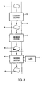
- a device for manufacturing a razor blade 4 with an edge portion 6 with a cutting edge 7 and a further portion 8 bent relative to that further portion 8 is shown in Fig. 3 .
- the device includes a hardening station 14 for hardening blanks 19 from which the razor blades 4 are to be made, a grinding station 15 for grinding the hardened razor blades 4, a laser bending station 16 for bending the hardened razor blades 4, and a transport path 18 for transporting the blanks 19, from which razor blades 4 are manufactured, from the hardening station 14 to the grinding station 15 and then to the bending station 16.
- the bending station is provided with a laser source 17.
- the blanks 19 from which the razor blades 4 are made are first hardened by thermal treatment in the hardening station 14. At least the cutting edges 7 of the razor blades 4 are very hard to achieve sufficient resistance to wear, the hardness being usually more than 650 HV and preferably more than 700 HV. Because of its corrosion resistance, heat treated (martensitic) stainless steel, preferably having a carbon content of at least 0.5 % and preferably between 0.5 and 1,25 %, is preferred for wet shaving. However, the razor blades 4 may be made of other types of steel hardened by heat treatment, such as carbon steel and high speed steel, as well. Also plasma nitrited steel is hardened and suitable as a material for razor blades 4. A particularly durable razor blade 4 can be obtained if it is made of tungsten carbide. The razor blades 4 may further be provided with coatings, for example for reducing wear and friction and for improving corrosion resistance.
- the blanks 19 are transported along the transport path 18 to the grinding station 15 where the cutting edge 7 is ground. Handling of the blanks 19 is relatively easy, because the blanks 19 are in an essentially flat condition. According to the present example, processing of the blanks 19 is facilitated particularly because the blanks 19 are flat during and directly after hardening and during and directly after grinding.
- the blanks 19 are transported along the transport path 18 to the bending station 16, where the edge portions 6 of the blanks 19, that have been ground so that cutting edges 7 have been formed, are bent relative to the further portion 8 of the blank 19.
- the further portion 8 of the blank 19 may also be bent along a fold line once or more times, so that two or more bends or folds are obtained.
- the bending of the hardened blank 19 includes locally heating portions of the blanks 19.
- the bending may be achieved or at least supported by exerting a bending moment to the heated portions. Because the bending moment is exerted to the material while it is heated, preferably to at least 500 °C, the blanks 19 can be bent through a substantial angle and with a relatively small radius of curvature after hardening. Furthermore, because the blanks 19 are heated locally only, the cutting edges 7 are not affected by the heating, so that the sharpness and hardness of the cutting edges 7 is maintained.
- the bending moment may be exerted statically, so that the blanks 19, which are heated most on one side, are prevented from bending. As a result, the material is deformed and then bent as the deformed heated side of the heated portion of the blank 19 shrinks while cooling.
- the bending moment may also be exerted dynamically by a tool that is movable or by a tool that is deflected in the transport direction of the blanks 19 (parallel to the orientation of the cutting edges 7) to actively bend the hot portions of the blanks 19. A combination of bending by moving a tool and bending due to shrinkage during cooling is also possible.
- the local heating of the blanks 19 is carried out by local irradiation of the area where the blank 19 is to be bent with a laser.
- Laser bending preferably involves intermittently irradiating the fold line or bending zone of a blank with laser light, either by scanning along the line or zone and/or by generating a suitably shaped laser light beam.
- the laser beam emitted from the laser source is directed to a face of the blank 19 to be bent, causing the portion of the blank 19 to be deformed to be heated and cooled very quickly.
- the material at the irradiated side shrinks, so that the blank 19 becomes convex in the irradiated area.
- the bending does not require the exertion of mechanical forces on the blank 19. This is particularly favorable for bending very closely along the cutting edge, which would require the exertion of large forces to load the bending area with a given bending moment, which may easily lead to damage to the cutting edge.
- Another advantage of bending by intermittently irradiating with a laser is that the material thickness is increased in the area where the bend is made. This provides additional rigidity and provides at least partial compensation if loss of specific strength occurs due to the bending operation.
- the blanks 19 are bent through a substantial angle of at least 40° with a small radius of curvature of less than two times the material thickness.
- a small radius of curvature is advantageous for accurate control of the bending operation.
- a laser light-absorbing agent may be applied on one surface of the blank transmitting a laser light to improve the energy absorption in the irradiated area.
- the transport path is shown diagrammatically as a path extending through the stations 14-16, it may be provided in the form of any suitable structure for transporting blanks individually or batchwise from the hardening station 14 to the bending station 16, either directly or via one or more other stations such as the grinding station 15, and it does not need to extend through the station or stations.
- the razor blade does not need to be a razor blade for manual wet shaving implement, but may also be a razor blade suitable for use in, for instance, an electric shaver, which may be suitable for wet and/or lotion enhanced shaving.
Landscapes
- Engineering & Computer Science (AREA)
- Mechanical Engineering (AREA)
- Life Sciences & Earth Sciences (AREA)
- Forests & Forestry (AREA)
- Heat Treatment Of Articles (AREA)
- Dry Shavers And Clippers (AREA)
- Nonmetal Cutting Devices (AREA)
- Knives (AREA)
- Laser Beam Processing (AREA)
Claims (12)
- Rasierklinge (4), die einen Kantenabschnitt (6) mit einer Schneidkante (7) und einen weiteren Abschnitt (8) aufweist, wobei der Kantenabschnitt (6) relativ zu dem weiteren Abschnitt (8) durch einen Winkel von zumindest 40° und mit einem Krümmungsradius von weniger als zweimal eine Materialdicke der Klinge in einem von der Schneidkante (7) beabstandeten Biegebereich (9) gebogen ist, dadurch gekennzeichnet, dass der Kantenabschnitt (6) eine durch eine erste Wärmebehandlung gehärtete Materialstruktur aufweist, und dass der Biegebereich (9) eine lokal wieder erhitzte Struktur besitzt.
- Rasierklinge (4) nach Anspruch 1, dadurch gekennzeichnet, dass der Biegebereich (9) weniger als 1 mm von der Schneidkante (7) weg vorgesehen ist.
- Rasierklinge (4) nach Anspruch 1, dadurch gekennzeichnet, dass die Rasierklinge eine Klingenmaterialdicke (d) aufweist, wobei der Biegebereich (9) eine größere Dicke als die Klingenmaterialdicke (d) besitzt.
- Rasiereinheit (1) mit mindestens zwei Rasierklingen (4), welche parallel zueinander in einem Rasierkopf (3) angebracht sind, wobei jede Rasierklinge (4) einen Kantenabschnitt (6) mit einer Schneidkante (7) und einen weiteren Abschnitt (8) aufweist, wobei der Kantenabschnitt (6) relativ zu dem weiteren Abschnitt (8) durch einen Winkel von zumindest 40° und mit einem Krümmungsradius von weniger als zweimal eine Materialdicke der Klinge in einem von der Schneidkante (7) beabstandeten Biegebereich (9) gebogen ist, und wobei ein Abstand zwischen den weiteren Abschnitten (8) von mindestens zwei der Rasierklingen (4) vorhanden ist, dadurch gekennzeichnet, dass jede Rasierklinge (4) eine Rasierklinge (4) nach Anspruch 1, 2 oder 3 ist, wobei der Kantenabschnitt (6) von mindestens einer der mindestens zwei Rasierklingen (4) zu mindestens einer benachbarten Rasierklinge der mindestens zwei Rasierklingen (4) hin gebogen ist und zu der mindestens einen benachbarten Rasierklinge der mindestens zwei Rasierklingen (4) hin über einen Abstand senkrecht zu dem weiteren Klingenabschnitt (8) der Rasierklinge (4), der kleiner als der Abstand zwischen den weiteren Abschnitten (8) dieser mindestens zwei Rasierklingen (4) ist, hervorsteht.
- Rasiereinheit (1) mit mindestens zwei Rasierklingen (4), die parallel zueinander in einem Rasierkopf (3) angebracht sind, wobei jede Rasierklinge (4) einen Kantenabschnitt (6) mit einer Schneidkante (7) und einen weiteren Abschnitt (8) aufweist, wobei der Kantenabschnitt (6) relativ zu dem weiteren Abschnitt (8) durch einen Winkel von zumindest 40° und mit einem Krümmungsradius von weniger als zweimal eine Materialdicke der Klinge in einem von der Schneidkante (7) beabstandeten Biegebereich (9) gebogen ist, wobei ein Abstand zwischen den Schneidkanten (7) von mindestens zwei der Rasierklingen (4) vorhanden ist, dadurch gekennzeichnet, dass jede Rasierklinge (4) eine Rasierklinge (4) nach Anspruch 1, 2 oder 3 ist, wobei der Abstand zwischen aufeinanderfolgenden Schneidkanten (7) geringer als 1,2 mm ist.
- Rasiereinheit (1) mit mindestens vier Rasierklingen (4), die parallel zueinander in einem Rasierkopf (3) angebracht sind, wobei jede Rasierklinge (4) einen Kantenabschnitt (6) mit einer Schneidkante (7) und einen weiteren Abschnitt (8) aufweist, wobei der Kantenabschnitt (6) relativ zu dem weiteren Abschnitt (8) durch einen Winkel von zumindest 40° und mit einem Krümmungsradius von weniger als zweimal eine Materialdicke der Klinge in einem von der Schneidkante (7) beabstandeten Biegebereich (9) gebogen ist, wobei ein Abstand zwischen den Schneidkanten (7) vorhanden ist, dadurch gekennzeichnet, dass jede Rasierklinge (4) eine Rasierklinge (4) nach Anspruch 1, 2 oder 3 ist.
- Verfahren zur Herstellung einer Rasierklinge (4) aus einem Rohling (19), wonach die Rasierklinge (4) mit einem Kantenabschnitt (6) mit einer Schneidkante (7) und einem weiteren Abschnitt (8) versehen wird, wobei der Kantenabschnitt (6) relativ zu dem weiteren Abschnitt (8) durch einen Winkel von zumindest 40° und mit einem Krümmungsradius von weniger als zweimal eine Materialdicke der Klinge in einem von der Schneidkante (7) beabstandeten Biegebereich (9) gebogen wird, wobei dieser Schritt ebenfalls das Biegen des Rohlings (19) umfasst, dadurch gekennzeichnet, dass der Rohling (19) durch eine Wärmebehandlung gehärtet und anschließend, nach Härten des Rohlings, ein Teil des Rohlings (19) lokal wieder erhitzt wird, um den Kantenabschnitt (6) des Rohlings (19) relativ zu dem weiteren Abschnitt (8) des Rohlings (19) zu biegen.
- Verfahren nach Anspruch 7, dadurch gekennzeichnet, dass die lokale Erhitzung des Rohlings (19) durch lokales Bestrahlen des Rohlings (19) mit einem Laserstrahl durchgeführt wird.
- Verfahren nach Anspruch 7, dadurch gekennzeichnet, dass die Schneidkante (7) nach Härten und vor Biegen geschliffen wird.
- Vorrichtung zur Herstellung von Rasierklingen (4) aus Rohlingen (19), wobei die Rasierklingen (4) jeweils einen Kantenabschnitt (6) mit einer Schneidkante (7) und einen weiteren Abschnitt (8) aufweisen, wobei der Kantenabschnitt (6) relativ zu dem weiteren Abschnitt (8) durch einen Winkel von zumindest 40° und mit einem Krümmungsradius von weniger als zweimal eine Materialdicke der Klinge gebogen ist, wobei die Vorrichtung eine Härtungsstation (14) mit einer Wärmebehandlungsstruktur zur Härtung der Rohlinge (19),
eine Biegestation (16) zum Biegen der Rohlinge (19), wobei die Biegestation (16) eine Wiedererhitzungsstruktur (17) zur lokalen Erhitzung von Abschnitten der zu biegenden Rohlinge (19) enthält, sowie
eine Transportbahn (18) zum Transportieren der in der Härtungsstation (14) gehärteten Rohlinge (19) von der Härtungsstation (14) zu der Biegestation (16) umfasst. - Vorrichtung nach Anspruch 10, dadurch gekennzeichnet, dass die Wärmebehandlungsstruktur zur lokalen Erhitzung der Rohlinge (19) einen zum Bestrahlen der zu biegenden Abschnitte der Rohlinge (19) angeordneten Laser (17) enthält.
- Vorrichtung nach Anspruch 10, dadurch gekennzeichnet, dass die Vorrichtung weiterhin eine Schleifstation (15) zum Schleifen der Schneidkanten (7) enthält, die entlang der Transportbahn (18) zwischen der Härtungsstation (14) und der Biegestation (16) angeordnet ist.
Priority Applications (1)
| Application Number | Priority Date | Filing Date | Title |
|---|---|---|---|
| EP04744383A EP1644146B2 (de) | 2003-06-26 | 2004-06-23 | Gebogene rasierklingen und herstellung solcher rasierklingen |
Applications Claiming Priority (3)
| Application Number | Priority Date | Filing Date | Title |
|---|---|---|---|
| EP03101899 | 2003-06-26 | ||
| EP04744383A EP1644146B2 (de) | 2003-06-26 | 2004-06-23 | Gebogene rasierklingen und herstellung solcher rasierklingen |
| PCT/IB2004/050976 WO2004112986A1 (en) | 2003-06-26 | 2004-06-23 | Bent razor blades and manufacturing of such razor blades |
Publications (3)
| Publication Number | Publication Date |
|---|---|
| EP1644146A1 EP1644146A1 (de) | 2006-04-12 |
| EP1644146B1 EP1644146B1 (de) | 2006-12-13 |
| EP1644146B2 true EP1644146B2 (de) | 2010-10-06 |
Family
ID=33522418
Family Applications (1)
| Application Number | Title | Priority Date | Filing Date |
|---|---|---|---|
| EP04744383A Expired - Lifetime EP1644146B2 (de) | 2003-06-26 | 2004-06-23 | Gebogene rasierklingen und herstellung solcher rasierklingen |
Country Status (8)
| Country | Link |
|---|---|
| US (3) | US20070124939A1 (de) |
| EP (1) | EP1644146B2 (de) |
| JP (1) | JP4682130B2 (de) |
| KR (1) | KR101123162B1 (de) |
| CN (1) | CN100352573C (de) |
| AT (1) | ATE347945T1 (de) |
| DE (1) | DE602004003706T3 (de) |
| WO (1) | WO2004112986A1 (de) |
Cited By (1)
| Publication number | Priority date | Publication date | Assignee | Title |
|---|---|---|---|---|
| US9862108B2 (en) | 2011-10-06 | 2018-01-09 | Bic Violex S.A. | Razor blade, razor head, and method of manufacture |
Families Citing this family (35)
| Publication number | Priority date | Publication date | Assignee | Title |
|---|---|---|---|---|
| EP1715984B1 (de) * | 2004-02-05 | 2010-03-17 | Koninklijke Philips Electronics N.V. | Rasierkopf mit einem klingenstützglied mit reduzierter querschnittsfläche |
| US8322253B2 (en) | 2005-07-08 | 2012-12-04 | Stanley Black & Decker, Inc. | Method of manufacturing a utility knife blade having an induction hardened cutting edge |
| US7448135B2 (en) | 2006-03-29 | 2008-11-11 | The Gillette Company | Multi-blade razors |
| US7882640B2 (en) | 2006-03-29 | 2011-02-08 | The Gillette Company | Razor blades and razors |
| US8499462B2 (en) * | 2006-04-10 | 2013-08-06 | The Gillette Company | Cutting members for shaving razors |
| US8011104B2 (en) | 2006-04-10 | 2011-09-06 | The Gillette Company | Cutting members for shaving razors |
| US8443519B2 (en) * | 2006-09-15 | 2013-05-21 | The Gillette Company | Blade supports for use in shaving systems |
| US7897266B2 (en) * | 2007-02-09 | 2011-03-01 | Rovcal, Inc. | Personal grooming device having a tarnish resistant, hypoallergenic and/or antimicrobial silver alloy coating thereon |
| AU2009244489B2 (en) | 2008-05-05 | 2015-05-07 | Edgewell Personal Care Brands, Llc | Razor blade and method of manufacture |
| US9248579B2 (en) | 2008-07-16 | 2016-02-02 | The Gillette Company | Razors and razor cartridges |
| MX2011003331A (es) * | 2008-09-29 | 2011-04-26 | Gillette Co | Rasuradoras y cartuchos para rasuradora con un tramo total disminuido entre las hojas. |
| MX2011003330A (es) * | 2008-09-29 | 2011-04-26 | Gillette Co | Cartuchos para rasuradoras con ensamble de hoja perforado. |
| CN102281963B (zh) | 2008-12-19 | 2015-04-08 | 比克-维尔莱克 | 制造剃刀头部组件的方法和设备以及由此制得的组件 |
| CA2745350C (en) | 2008-12-19 | 2017-05-30 | Spiros Gratsias | Razor cartridge and mechanical razor comprising such a cartridge |
| KR101055684B1 (ko) | 2009-02-11 | 2011-08-09 | 주식회사 도루코 | 일체형 면도날 및 이를 이용한 면도기 카트리지 |
| EP2419247B1 (de) * | 2009-04-15 | 2020-05-27 | BIC-Violex S.A. | Verfahren zur Herstellung einer Rasiererkomponente, mit dem Verfahren hergestellter Träger sowie Rasierklingeneinheit und mechanischer Rasierer mit besagtem Träger |
| PL2266727T3 (pl) * | 2009-06-22 | 2016-04-29 | Gillette Co | Sposób wytwarzania funkcjonalnych wkładów maszynek do golenia |
| US20120192431A9 (en) * | 2009-11-18 | 2012-08-02 | Kevin James Wain | Blades for Shaving Razors |
| US20110162209A1 (en) * | 2010-01-06 | 2011-07-07 | Kevin James Wain | Blades for Shaving Razors |
| US20110314678A1 (en) * | 2010-06-29 | 2011-12-29 | Mark Peterson | Bent razor blades and manufacturing thereof |
| CN101966704A (zh) * | 2010-09-03 | 2011-02-09 | 姜飞进 | 弧形剃须刀头 |
| PL2763823T3 (pl) | 2011-10-06 | 2018-11-30 | Bic-Violex S.A. | Ostrze maszynki do golenia i głowica maszynki do golenia |
| EP2823942A1 (de) * | 2013-07-10 | 2015-01-14 | The Gillette Company | Rasierklingenkartuschen |
| JP6239134B2 (ja) * | 2014-08-25 | 2017-11-29 | ドルコ・カンパニー・リミテッドDorco Co., Ltd. | かみそりの刃及びこれを適用したかみそりカートリッジ |
| EP3127666B1 (de) * | 2014-08-25 | 2020-12-09 | Dorco Co., Ltd. | Rasierklingeneinheit und rasierapparat damit |
| US20160361828A1 (en) | 2015-06-11 | 2016-12-15 | The Gillette Company | Razor blade steel |
| EP3318374B1 (de) * | 2016-11-07 | 2019-08-07 | The Gillette Company | Gebogene rasierklingen und herstellung solcher rasierklingen |
| KR101718767B1 (ko) * | 2017-02-23 | 2017-03-22 | 주식회사 도루코 | 면도기 카트리지 및 이를 이용한 면도기 |
| CN208246877U (zh) * | 2017-08-25 | 2018-12-18 | 宁波开利控股集团股份有限公司 | 一种矩阵式排列的漏须刀头 |
| EP3453499A1 (de) * | 2017-09-11 | 2019-03-13 | The Gillette Company LLC | Haarentfernungsvorrichtung für schamhaar |
| KR102106304B1 (ko) * | 2018-07-27 | 2020-05-04 | 주식회사 도루코 | 면도기 카트리지 |
| PL3702117T3 (pl) | 2019-02-28 | 2022-10-31 | BIC Violex Single Member S.A. | Wygięte ostrze o zwiększonej sztywności |
| CN113544298A (zh) * | 2019-02-28 | 2021-10-22 | Edgewell个人护理品牌有限责任公司 | 剃刀刀片和用于剃刀刀片的组合物 |
| ES2983520T3 (es) * | 2020-03-18 | 2024-10-23 | Bic Violex Single Member Sa | Miembro de corte para maquinillas de afeitar con múltiples cuchillas que tienen una plataforma estrecha para facilitar el enjuague |
| KR20250007858A (ko) * | 2023-07-06 | 2025-01-14 | 주식회사 도루코 | 면도기 카트리지 |
Citations (2)
| Publication number | Priority date | Publication date | Assignee | Title |
|---|---|---|---|---|
| US972436A (en) † | 1910-08-06 | 1910-10-11 | Osroe A Clark | Process of making blades with soft centers. |
| GB2055069A (en) † | 1979-08-01 | 1981-02-25 | Wilkinson Sword Ltd | Shaving units |
Family Cites Families (50)
| Publication number | Priority date | Publication date | Assignee | Title |
|---|---|---|---|---|
| US1672516A (en) * | 1926-08-21 | 1928-06-05 | Wade And Butcher Corp | Method of making curved razor blades |
| US1914013A (en) | 1928-03-10 | 1933-06-13 | Gillette Safety Razor Co | Metal strip sharpening machine |
| BE364924A (de) * | 1928-11-08 | |||
| US2087051A (en) * | 1933-12-21 | 1937-07-13 | Gillette Safety Razor Co | Fine edge blade and method of making the same |
| DE877617C (de) | 1944-01-20 | 1953-05-26 | Deutsche Edelstahlwerke Ag | Verfahren und Vorrichtung zum Biegen und Abkanten von Blechen und Platten |
| GB643367A (en) | 1947-10-31 | 1950-09-20 | Anders Goeran Molinder | Improvements in or relating to the thermal treatment of steel and products thereof |
| US3224900A (en) * | 1962-10-04 | 1965-12-21 | Philip Morris Inc | Method of making polyethylene coated razor blades |
| GB1102041A (en) | 1966-02-04 | 1968-02-07 | Peter Drummond | Automatic grinding method and apparatus |
| US3461616A (en) * | 1966-10-14 | 1969-08-19 | Gillette Co | Methods and apparatus for sharpening razor blades or similar cutting tools |
| US3431624A (en) * | 1966-10-14 | 1969-03-11 | Gillette Co | Strip inspection system |
| US3489589A (en) * | 1966-10-14 | 1970-01-13 | Gillette Co | Razor blade coating method and apparatus |
| US3644992A (en) * | 1970-04-07 | 1972-02-29 | Sylvania Electric Prod | Razor assembly |
| US3852883A (en) * | 1973-01-23 | 1974-12-10 | Warner Lambert Co | Shaving unit for safety razor |
| HU167659B (de) * | 1973-12-22 | 1975-11-28 | ||
| US3938250A (en) * | 1974-05-15 | 1976-02-17 | The Gillette Company | Disposable blade unit |
| GB1591095A (en) * | 1976-11-16 | 1981-06-17 | Wilkinson Sword Ltd | Shaving units |
| GB1598352A (en) * | 1977-11-26 | 1981-09-16 | Wilkinson Sword Ltd | Manufacture of razor blades |
| DE2918100A1 (de) | 1979-05-04 | 1980-11-13 | Siemens Ag | Automatisiertes justieren in der feinwerktechnik |
| US4378634A (en) * | 1979-12-07 | 1983-04-05 | The Gillette Company | Razor blade assembly |
| US4275498A (en) * | 1979-12-31 | 1981-06-30 | Warner-Lambert Company | Safety razor blade cartridge |
| US4302876A (en) * | 1980-03-14 | 1981-12-01 | Warner-Lambert Company | Razor blade with inclined edge |
| US4442598A (en) * | 1981-01-30 | 1984-04-17 | The Gillette Company | Razor blade assembly |
| US4389773A (en) * | 1981-04-30 | 1983-06-28 | The Gillette Company | Shaving implement |
| US4498235A (en) | 1982-09-17 | 1985-02-12 | The Gillette Company | Razor blade assembly |
| DE3235714A1 (de) | 1982-09-27 | 1984-03-29 | Siemens AG, 1000 Berlin und 8000 München | Verfahren und vorrichtung zum justieren von kontaktfedern in einem relais |
| DE3728041A1 (de) | 1987-08-22 | 1989-03-02 | Messer Griesheim Gmbh | Verfahren zur herstellung von biegeteilen aus vorverfestigten metallen durch kaltumformung |
| US4860452A (en) * | 1988-12-12 | 1989-08-29 | The Stanley Works | Single edge razor blade with integral back |
| JP2623817B2 (ja) * | 1989-02-20 | 1997-06-25 | 富士通株式会社 | レーザビームによる曲げ加工方法および曲げ加工装置 |
| US5010646A (en) * | 1990-01-26 | 1991-04-30 | The Gillette Company | Shaving system |
| FR2663255A2 (fr) * | 1990-04-09 | 1991-12-20 | Canovas Gines | Ensemble de rasage humide a lames avec suspension magnetique. |
| US5048191A (en) * | 1990-06-08 | 1991-09-17 | The Gillette Company | Razor blade technology |
| US5067238A (en) * | 1990-09-28 | 1991-11-26 | The Gillette Company | Shaving system |
| DE69011118T2 (de) * | 1990-11-10 | 1995-03-30 | Hitachi Metals Ltd | Korrosionsbeständiger Stahl für Rasierklingen,Rasierklingen und Herstellungsverfahren. |
| DE4228528A1 (de) * | 1991-08-29 | 1993-03-04 | Okuma Machinery Works Ltd | Verfahren und vorrichtung zur metallblechverarbeitung |
| EP1645376B1 (de) | 1991-11-27 | 2008-02-20 | The Gillette Company | Rasierapparate |
| DE59202090D1 (de) * | 1992-02-14 | 1995-06-08 | Wilkinson Sword Gmbh | Rasierapparatekopf, insbesondere Rasierklingeneinheit, eines Nassrasierapparates. |
| DE9205955U1 (de) | 1992-05-02 | 1993-09-09 | Wilkinson Sword Gmbh, 42659 Solingen | Rasierapparatekopf, insbesondere Rasierklingeneinheit eines Naßrasierapparates |
| WO1995004637A1 (en) | 1993-08-04 | 1995-02-16 | Warner-Lambert Company | Dynamic shaving system |
| GB9320058D0 (en) * | 1993-09-29 | 1993-11-17 | Gillette Co | Savety razors |
| KR100394824B1 (ko) * | 1994-10-03 | 2003-11-28 | 더 지렛트 캄파니 | 면도칼블레이드조립체 |
| EP0731978B1 (de) | 1994-10-04 | 1998-06-10 | Koninklijke Philips Electronics N.V. | Verfahren zur regelung der schaltstrecke in einem reed-schalter |
| JP2796622B2 (ja) * | 1996-03-07 | 1998-09-10 | セイコーインスツルメンツ株式会社 | 微細加工方法および微細加工構造物 |
| US5822862A (en) * | 1997-01-17 | 1998-10-20 | Warner-Lambert Co. | Suspended blade shaving system |
| AT407615B (de) * | 1997-07-02 | 2001-05-25 | Inst Spanlose Fertigung Und Ho | Verfahren zum biegen mit laserunterstützung |
| WO1999014020A1 (en) * | 1997-09-18 | 1999-03-25 | The Gillette Company | Safety razors |
| JP2000218447A (ja) * | 1999-02-01 | 2000-08-08 | Daido Steel Co Ltd | 刃物の製造方法 |
| GB0025339D0 (en) | 2000-10-16 | 2000-11-29 | Gillette Co | Safety razors |
| JP4176968B2 (ja) * | 2001-02-14 | 2008-11-05 | 富士通株式会社 | レーザ曲げ加工方法及びレーザ曲げ加工装置 |
| DE60229687D1 (de) * | 2001-04-27 | 2008-12-18 | Eveready Battery Inc | Nassrasierapparat mit vier Klingen, und Kassette dafür |
| US8499462B2 (en) * | 2006-04-10 | 2013-08-06 | The Gillette Company | Cutting members for shaving razors |
-
2004
- 2004-06-23 EP EP04744383A patent/EP1644146B2/de not_active Expired - Lifetime
- 2004-06-23 WO PCT/IB2004/050976 patent/WO2004112986A1/en not_active Ceased
- 2004-06-23 US US10/561,468 patent/US20070124939A1/en not_active Abandoned
- 2004-06-23 AT AT04744383T patent/ATE347945T1/de not_active IP Right Cessation
- 2004-06-23 KR KR1020057024516A patent/KR101123162B1/ko not_active Expired - Fee Related
- 2004-06-23 DE DE602004003706T patent/DE602004003706T3/de not_active Expired - Lifetime
- 2004-06-23 CN CNB2004800179444A patent/CN100352573C/zh not_active Expired - Fee Related
- 2004-06-23 JP JP2006516746A patent/JP4682130B2/ja not_active Expired - Fee Related
-
2011
- 2011-06-20 US US13/164,004 patent/US20110239466A1/en not_active Abandoned
-
2013
- 2013-03-08 US US13/790,913 patent/US9868221B2/en not_active Expired - Fee Related
Patent Citations (2)
| Publication number | Priority date | Publication date | Assignee | Title |
|---|---|---|---|---|
| US972436A (en) † | 1910-08-06 | 1910-10-11 | Osroe A Clark | Process of making blades with soft centers. |
| GB2055069A (en) † | 1979-08-01 | 1981-02-25 | Wilkinson Sword Ltd | Shaving units |
Cited By (7)
| Publication number | Priority date | Publication date | Assignee | Title |
|---|---|---|---|---|
| US9862108B2 (en) | 2011-10-06 | 2018-01-09 | Bic Violex S.A. | Razor blade, razor head, and method of manufacture |
| US10220532B2 (en) | 2011-10-06 | 2019-03-05 | Bic Violex Sa | Razor blade, razor head, and method of manufacture |
| US10220533B2 (en) | 2011-10-06 | 2019-03-05 | Bic Violex Sa | Razor blade, razor head, and method of manufacture |
| US10391651B2 (en) | 2011-10-06 | 2019-08-27 | Bic-Violex Sa | Razor blade, razor head, and method of manufacture |
| US10500745B2 (en) | 2011-10-06 | 2019-12-10 | Bic Violex Sa | Razor blade, razor head, and method of manufacture |
| US10744660B2 (en) | 2011-10-06 | 2020-08-18 | Bic Violex S.A. | Razor blade, razor head, and method of manufacture |
| US10843355B2 (en) | 2011-10-06 | 2020-11-24 | Bic-Violex Sa | Razor blade, razor head, and method of manufacture |
Also Published As
| Publication number | Publication date |
|---|---|
| US9868221B2 (en) | 2018-01-16 |
| KR20060023995A (ko) | 2006-03-15 |
| CN100352573C (zh) | 2007-12-05 |
| EP1644146A1 (de) | 2006-04-12 |
| DE602004003706T2 (de) | 2007-10-04 |
| US20130185942A1 (en) | 2013-07-25 |
| CN1812856A (zh) | 2006-08-02 |
| ATE347945T1 (de) | 2007-01-15 |
| JP4682130B2 (ja) | 2011-05-11 |
| KR101123162B1 (ko) | 2012-03-19 |
| DE602004003706T3 (de) | 2011-05-05 |
| DE602004003706D1 (de) | 2007-01-25 |
| WO2004112986A1 (en) | 2004-12-29 |
| US20110239466A1 (en) | 2011-10-06 |
| JP2007518436A (ja) | 2007-07-12 |
| EP1644146B1 (de) | 2006-12-13 |
| US20070124939A1 (en) | 2007-06-07 |
Similar Documents
| Publication | Publication Date | Title |
|---|---|---|
| EP1644146B2 (de) | Gebogene rasierklingen und herstellung solcher rasierklingen | |
| US8640344B2 (en) | Cutting members for shaving razors | |
| US20050198837A1 (en) | Shaving razors with multiple blades | |
| EP1301297B1 (de) | Rasierklinge und herstellungsverfahren | |
| WO1994024945A1 (en) | Surgical saw blade | |
| CN103282167B (zh) | 用于制造附连到支承件上的剃须刀座的切削刃部的方法 | |
| US2817146A (en) | Safety razor and guard means therefor | |
| CN109906135B (zh) | 弯曲剃刀刀片和此类剃刀刀片的制造 | |
| AU2008319174B2 (en) | Razor blade and method of manufacture | |
| WO2007049218A1 (en) | Method for manufacturing razor blades | |
| MXPA99007592A (en) | Safety razors | |
| CA2640017A1 (en) | Cutting members for shaving razors |
Legal Events
| Date | Code | Title | Description |
|---|---|---|---|
| PUAI | Public reference made under article 153(3) epc to a published international application that has entered the european phase |
Free format text: ORIGINAL CODE: 0009012 |
|
| 17P | Request for examination filed |
Effective date: 20060126 |
|
| AK | Designated contracting states |
Kind code of ref document: A1 Designated state(s): AT BE BG CH CY CZ DE DK EE ES FI FR GB GR HU IE IT LI LU MC NL PL PT RO SE SI SK TR |
|
| GRAP | Despatch of communication of intention to grant a patent |
Free format text: ORIGINAL CODE: EPIDOSNIGR1 |
|
| DAX | Request for extension of the european patent (deleted) | ||
| GRAS | Grant fee paid |
Free format text: ORIGINAL CODE: EPIDOSNIGR3 |
|
| GRAA | (expected) grant |
Free format text: ORIGINAL CODE: 0009210 |
|
| AK | Designated contracting states |
Kind code of ref document: B1 Designated state(s): AT BE BG CH CY CZ DE DK EE ES FI FR GB GR HU IE IT LI LU MC NL PL PT RO SE SI SK TR |
|
| PG25 | Lapsed in a contracting state [announced via postgrant information from national office to epo] |
Ref country code: IT Free format text: LAPSE BECAUSE OF FAILURE TO SUBMIT A TRANSLATION OF THE DESCRIPTION OR TO PAY THE FEE WITHIN THE PRESCRIBED TIME-LIMIT;WARNING: LAPSES OF ITALIAN PATENTS WITH EFFECTIVE DATE BEFORE 2007 MAY HAVE OCCURRED AT ANY TIME BEFORE 2007. THE CORRECT EFFECTIVE DATE MAY BE DIFFERENT FROM THE ONE RECORDED. Effective date: 20061213 Ref country code: SK Free format text: LAPSE BECAUSE OF FAILURE TO SUBMIT A TRANSLATION OF THE DESCRIPTION OR TO PAY THE FEE WITHIN THE PRESCRIBED TIME-LIMIT Effective date: 20061213 Ref country code: AT Free format text: LAPSE BECAUSE OF FAILURE TO SUBMIT A TRANSLATION OF THE DESCRIPTION OR TO PAY THE FEE WITHIN THE PRESCRIBED TIME-LIMIT Effective date: 20061213 Ref country code: CH Free format text: LAPSE BECAUSE OF FAILURE TO SUBMIT A TRANSLATION OF THE DESCRIPTION OR TO PAY THE FEE WITHIN THE PRESCRIBED TIME-LIMIT Effective date: 20061213 Ref country code: LI Free format text: LAPSE BECAUSE OF FAILURE TO SUBMIT A TRANSLATION OF THE DESCRIPTION OR TO PAY THE FEE WITHIN THE PRESCRIBED TIME-LIMIT Effective date: 20061213 Ref country code: FI Free format text: LAPSE BECAUSE OF FAILURE TO SUBMIT A TRANSLATION OF THE DESCRIPTION OR TO PAY THE FEE WITHIN THE PRESCRIBED TIME-LIMIT Effective date: 20061213 Ref country code: RO Free format text: LAPSE BECAUSE OF FAILURE TO SUBMIT A TRANSLATION OF THE DESCRIPTION OR TO PAY THE FEE WITHIN THE PRESCRIBED TIME-LIMIT Effective date: 20061213 Ref country code: PL Free format text: LAPSE BECAUSE OF FAILURE TO SUBMIT A TRANSLATION OF THE DESCRIPTION OR TO PAY THE FEE WITHIN THE PRESCRIBED TIME-LIMIT Effective date: 20061213 Ref country code: DK Free format text: LAPSE BECAUSE OF FAILURE TO SUBMIT A TRANSLATION OF THE DESCRIPTION OR TO PAY THE FEE WITHIN THE PRESCRIBED TIME-LIMIT Effective date: 20061213 Ref country code: NL Free format text: LAPSE BECAUSE OF FAILURE TO SUBMIT A TRANSLATION OF THE DESCRIPTION OR TO PAY THE FEE WITHIN THE PRESCRIBED TIME-LIMIT Effective date: 20061213 Ref country code: BE Free format text: LAPSE BECAUSE OF FAILURE TO SUBMIT A TRANSLATION OF THE DESCRIPTION OR TO PAY THE FEE WITHIN THE PRESCRIBED TIME-LIMIT Effective date: 20061213 Ref country code: CZ Free format text: LAPSE BECAUSE OF FAILURE TO SUBMIT A TRANSLATION OF THE DESCRIPTION OR TO PAY THE FEE WITHIN THE PRESCRIBED TIME-LIMIT Effective date: 20061213 Ref country code: SI Free format text: LAPSE BECAUSE OF FAILURE TO SUBMIT A TRANSLATION OF THE DESCRIPTION OR TO PAY THE FEE WITHIN THE PRESCRIBED TIME-LIMIT Effective date: 20061213 |
|
| REG | Reference to a national code |
Ref country code: GB Ref legal event code: FG4D |
|
| REG | Reference to a national code |
Ref country code: CH Ref legal event code: EP |
|
| REG | Reference to a national code |
Ref country code: IE Ref legal event code: FG4D |
|
| REF | Corresponds to: |
Ref document number: 602004003706 Country of ref document: DE Date of ref document: 20070125 Kind code of ref document: P |
|
| PG25 | Lapsed in a contracting state [announced via postgrant information from national office to epo] |
Ref country code: SE Free format text: LAPSE BECAUSE OF FAILURE TO SUBMIT A TRANSLATION OF THE DESCRIPTION OR TO PAY THE FEE WITHIN THE PRESCRIBED TIME-LIMIT Effective date: 20070313 Ref country code: BG Free format text: LAPSE BECAUSE OF FAILURE TO SUBMIT A TRANSLATION OF THE DESCRIPTION OR TO PAY THE FEE WITHIN THE PRESCRIBED TIME-LIMIT Effective date: 20070313 |
|
| PG25 | Lapsed in a contracting state [announced via postgrant information from national office to epo] |
Ref country code: ES Free format text: LAPSE BECAUSE OF FAILURE TO SUBMIT A TRANSLATION OF THE DESCRIPTION OR TO PAY THE FEE WITHIN THE PRESCRIBED TIME-LIMIT Effective date: 20070324 |
|
| PG25 | Lapsed in a contracting state [announced via postgrant information from national office to epo] |
Ref country code: PT Free format text: LAPSE BECAUSE OF FAILURE TO SUBMIT A TRANSLATION OF THE DESCRIPTION OR TO PAY THE FEE WITHIN THE PRESCRIBED TIME-LIMIT Effective date: 20070514 |
|
| NLV1 | Nl: lapsed or annulled due to failure to fulfill the requirements of art. 29p and 29m of the patents act | ||
| ET | Fr: translation filed | ||
| REG | Reference to a national code |
Ref country code: CH Ref legal event code: PL |
|
| PLBI | Opposition filed |
Free format text: ORIGINAL CODE: 0009260 |
|
| PLAX | Notice of opposition and request to file observation + time limit sent |
Free format text: ORIGINAL CODE: EPIDOSNOBS2 |
|
| 26 | Opposition filed |
Opponent name: EVEREADY BATTERY COMPANY, INC. Effective date: 20070913 |
|
| PLAF | Information modified related to communication of a notice of opposition and request to file observations + time limit |
Free format text: ORIGINAL CODE: EPIDOSCOBS2 |
|
| PG25 | Lapsed in a contracting state [announced via postgrant information from national office to epo] |
Ref country code: MC Free format text: LAPSE BECAUSE OF NON-PAYMENT OF DUE FEES Effective date: 20070630 |
|
| PLBB | Reply of patent proprietor to notice(s) of opposition received |
Free format text: ORIGINAL CODE: EPIDOSNOBS3 |
|
| PG25 | Lapsed in a contracting state [announced via postgrant information from national office to epo] |
Ref country code: GR Free format text: LAPSE BECAUSE OF FAILURE TO SUBMIT A TRANSLATION OF THE DESCRIPTION OR TO PAY THE FEE WITHIN THE PRESCRIBED TIME-LIMIT Effective date: 20070314 |
|
| PG25 | Lapsed in a contracting state [announced via postgrant information from national office to epo] |
Ref country code: IE Free format text: LAPSE BECAUSE OF NON-PAYMENT OF DUE FEES Effective date: 20070625 |
|
| PG25 | Lapsed in a contracting state [announced via postgrant information from national office to epo] |
Ref country code: EE Free format text: LAPSE BECAUSE OF FAILURE TO SUBMIT A TRANSLATION OF THE DESCRIPTION OR TO PAY THE FEE WITHIN THE PRESCRIBED TIME-LIMIT Effective date: 20061213 |
|
| PG25 | Lapsed in a contracting state [announced via postgrant information from national office to epo] |
Ref country code: CY Free format text: LAPSE BECAUSE OF FAILURE TO SUBMIT A TRANSLATION OF THE DESCRIPTION OR TO PAY THE FEE WITHIN THE PRESCRIBED TIME-LIMIT Effective date: 20061213 Ref country code: LU Free format text: LAPSE BECAUSE OF NON-PAYMENT OF DUE FEES Effective date: 20070623 |
|
| PG25 | Lapsed in a contracting state [announced via postgrant information from national office to epo] |
Ref country code: TR Free format text: LAPSE BECAUSE OF FAILURE TO SUBMIT A TRANSLATION OF THE DESCRIPTION OR TO PAY THE FEE WITHIN THE PRESCRIBED TIME-LIMIT Effective date: 20061213 Ref country code: HU Free format text: LAPSE BECAUSE OF FAILURE TO SUBMIT A TRANSLATION OF THE DESCRIPTION OR TO PAY THE FEE WITHIN THE PRESCRIBED TIME-LIMIT Effective date: 20070614 |
|
| APBM | Appeal reference recorded |
Free format text: ORIGINAL CODE: EPIDOSNREFNO |
|
| APBP | Date of receipt of notice of appeal recorded |
Free format text: ORIGINAL CODE: EPIDOSNNOA2O |
|
| APAH | Appeal reference modified |
Free format text: ORIGINAL CODE: EPIDOSCREFNO |
|
| APBQ | Date of receipt of statement of grounds of appeal recorded |
Free format text: ORIGINAL CODE: EPIDOSNNOA3O |
|
| PLAB | Opposition data, opponent's data or that of the opponent's representative modified |
Free format text: ORIGINAL CODE: 0009299OPPO |
|
| R26 | Opposition filed (corrected) |
Opponent name: EVEREADY BATTERY COMPANY, INC. Effective date: 20070913 |
|
| APBU | Appeal procedure closed |
Free format text: ORIGINAL CODE: EPIDOSNNOA9O |
|
| PUAH | Patent maintained in amended form |
Free format text: ORIGINAL CODE: 0009272 |
|
| STAA | Information on the status of an ep patent application or granted ep patent |
Free format text: STATUS: PATENT MAINTAINED AS AMENDED |
|
| 27A | Patent maintained in amended form |
Effective date: 20101006 |
|
| AK | Designated contracting states |
Kind code of ref document: B2 Designated state(s): AT BE BG CH CY CZ DE DK EE ES FI FR GB GR HU IE IT LI LU MC NL PL PT RO SE SI SK TR |
|
| REG | Reference to a national code |
Ref country code: ES Ref legal event code: FD2A Effective date: 20110715 |
|
| PG25 | Lapsed in a contracting state [announced via postgrant information from national office to epo] |
Ref country code: ES Free format text: LAPSE BECAUSE OF FAILURE TO SUBMIT A TRANSLATION OF THE DESCRIPTION OR TO PAY THE FEE WITHIN THE PRESCRIBED TIME-LIMIT Effective date: 20100624 |
|
| REG | Reference to a national code |
Ref country code: DE Ref legal event code: R082 Ref document number: 602004003706 Country of ref document: DE Representative=s name: VOLMER, GEORG, DIPL.-ING., DE |
|
| REG | Reference to a national code |
Ref country code: DE Ref legal event code: R082 Ref document number: 602004003706 Country of ref document: DE Representative=s name: MEISSNER, BOLTE & PARTNER GBR, DE Effective date: 20140328 Ref country code: DE Ref legal event code: R082 Ref document number: 602004003706 Country of ref document: DE Representative=s name: MEISSNER BOLTE PATENTANWAELTE RECHTSANWAELTE P, DE Effective date: 20140328 Ref country code: DE Ref legal event code: R081 Ref document number: 602004003706 Country of ref document: DE Owner name: KONINKLIJKE PHILIPS N.V., NL Free format text: FORMER OWNER: KONINKLIJKE PHILIPS ELECTRONICS N.V., EINDHOVEN, NL Effective date: 20140328 Ref country code: DE Ref legal event code: R082 Ref document number: 602004003706 Country of ref document: DE Representative=s name: VOLMER, GEORG, DIPL.-ING., DE Effective date: 20140328 |
|
| REG | Reference to a national code |
Ref country code: FR Ref legal event code: CD Owner name: KONINKLIJKE PHILIPS ELECTRONICS N.V., NL Effective date: 20141126 Ref country code: FR Ref legal event code: CA Effective date: 20141126 |
|
| REG | Reference to a national code |
Ref country code: DE Ref legal event code: R082 Ref document number: 602004003706 Country of ref document: DE Representative=s name: MEISSNER, BOLTE & PARTNER GBR, DE Ref country code: DE Ref legal event code: R082 Ref document number: 602004003706 Country of ref document: DE Representative=s name: MEISSNER BOLTE PATENTANWAELTE RECHTSANWAELTE P, DE |
|
| REG | Reference to a national code |
Ref country code: FR Ref legal event code: PLFP Year of fee payment: 13 |
|
| REG | Reference to a national code |
Ref country code: FR Ref legal event code: PLFP Year of fee payment: 14 |
|
| REG | Reference to a national code |
Ref country code: FR Ref legal event code: PLFP Year of fee payment: 15 |
|
| PGFP | Annual fee paid to national office [announced via postgrant information from national office to epo] |
Ref country code: DE Payment date: 20210628 Year of fee payment: 18 Ref country code: FR Payment date: 20210625 Year of fee payment: 18 |
|
| PGFP | Annual fee paid to national office [announced via postgrant information from national office to epo] |
Ref country code: GB Payment date: 20210625 Year of fee payment: 18 |
|
| REG | Reference to a national code |
Ref country code: DE Ref legal event code: R119 Ref document number: 602004003706 Country of ref document: DE |
|
| GBPC | Gb: european patent ceased through non-payment of renewal fee |
Effective date: 20220623 |
|
| PG25 | Lapsed in a contracting state [announced via postgrant information from national office to epo] |
Ref country code: FR Free format text: LAPSE BECAUSE OF NON-PAYMENT OF DUE FEES Effective date: 20220630 |
|
| PG25 | Lapsed in a contracting state [announced via postgrant information from national office to epo] |
Ref country code: GB Free format text: LAPSE BECAUSE OF NON-PAYMENT OF DUE FEES Effective date: 20220623 Ref country code: DE Free format text: LAPSE BECAUSE OF NON-PAYMENT OF DUE FEES Effective date: 20230103 |