EP1640537B1 - Dispositif d'arrêt amortissant et stabilisant pour portes et volets coulissantes - Google Patents
Dispositif d'arrêt amortissant et stabilisant pour portes et volets coulissantes Download PDFInfo
- Publication number
- EP1640537B1 EP1640537B1 EP05019200A EP05019200A EP1640537B1 EP 1640537 B1 EP1640537 B1 EP 1640537B1 EP 05019200 A EP05019200 A EP 05019200A EP 05019200 A EP05019200 A EP 05019200A EP 1640537 B1 EP1640537 B1 EP 1640537B1
- Authority
- EP
- European Patent Office
- Prior art keywords
- carriage
- boss
- base unit
- cam
- arms
- Prior art date
- Legal status (The legal status is an assumption and is not a legal conclusion. Google has not performed a legal analysis and makes no representation as to the accuracy of the status listed.)
- Not-in-force
Links
Images


Classifications
-
- E—FIXED CONSTRUCTIONS
- E05—LOCKS; KEYS; WINDOW OR DOOR FITTINGS; SAFES
- E05B—LOCKS; ACCESSORIES THEREFOR; HANDCUFFS
- E05B65/00—Locks or fastenings for special use
- E05B65/08—Locks or fastenings for special use for sliding wings
- E05B65/0811—Locks or fastenings for special use for sliding wings the bolts pivoting about an axis perpendicular to the wings
- E05B65/0829—Locks or fastenings for special use for sliding wings the bolts pivoting about an axis perpendicular to the wings mounted on the slide guide, e.g. the rail
-
- E—FIXED CONSTRUCTIONS
- E05—LOCKS; KEYS; WINDOW OR DOOR FITTINGS; SAFES
- E05F—DEVICES FOR MOVING WINGS INTO OPEN OR CLOSED POSITION; CHECKS FOR WINGS; WING FITTINGS NOT OTHERWISE PROVIDED FOR, CONCERNED WITH THE FUNCTIONING OF THE WING
- E05F5/00—Braking devices, e.g. checks; Stops; Buffers
- E05F5/02—Braking devices, e.g. checks; Stops; Buffers specially for preventing the slamming of swinging wings during final closing movement, e.g. jamb stops
- E05F5/027—Braking devices, e.g. checks; Stops; Buffers specially for preventing the slamming of swinging wings during final closing movement, e.g. jamb stops with closing action
-
- E—FIXED CONSTRUCTIONS
- E05—LOCKS; KEYS; WINDOW OR DOOR FITTINGS; SAFES
- E05B—LOCKS; ACCESSORIES THEREFOR; HANDCUFFS
- E05B17/00—Accessories in connection with locks
- E05B17/0045—Silencing devices; Noise reduction
-
- E—FIXED CONSTRUCTIONS
- E05—LOCKS; KEYS; WINDOW OR DOOR FITTINGS; SAFES
- E05F—DEVICES FOR MOVING WINGS INTO OPEN OR CLOSED POSITION; CHECKS FOR WINGS; WING FITTINGS NOT OTHERWISE PROVIDED FOR, CONCERNED WITH THE FUNCTIONING OF THE WING
- E05F5/00—Braking devices, e.g. checks; Stops; Buffers
- E05F5/003—Braking devices, e.g. checks; Stops; Buffers for sliding wings
-
- E—FIXED CONSTRUCTIONS
- E05—LOCKS; KEYS; WINDOW OR DOOR FITTINGS; SAFES
- E05Y—INDEXING SCHEME RELATING TO HINGES OR OTHER SUSPENSION DEVICES FOR DOORS, WINDOWS OR WINGS AND DEVICES FOR MOVING WINGS INTO OPEN OR CLOSED POSITION, CHECKS FOR WINGS AND WING FITTINGS NOT OTHERWISE PROVIDED FOR, CONCERNED WITH THE FUNCTIONING OF THE WING
- E05Y2800/00—Details, accessories and auxiliary operations not otherwise provided for
- E05Y2800/15—Applicability
- E05Y2800/17—Universally applicable
- E05Y2800/172—Universally applicable on different wing or frame locations
- E05Y2800/174—Universally applicable on different wing or frame locations on the left or right side
-
- E—FIXED CONSTRUCTIONS
- E05—LOCKS; KEYS; WINDOW OR DOOR FITTINGS; SAFES
- E05Y—INDEXING SCHEME RELATING TO HINGES OR OTHER SUSPENSION DEVICES FOR DOORS, WINDOWS OR WINGS AND DEVICES FOR MOVING WINGS INTO OPEN OR CLOSED POSITION, CHECKS FOR WINGS AND WING FITTINGS NOT OTHERWISE PROVIDED FOR, CONCERNED WITH THE FUNCTIONING OF THE WING
- E05Y2900/00—Application of doors, windows, wings or fittings thereof
- E05Y2900/10—Application of doors, windows, wings or fittings thereof for buildings or parts thereof
- E05Y2900/13—Application of doors, windows, wings or fittings thereof for buildings or parts thereof characterised by the type of wing
- E05Y2900/132—Doors
-
- E—FIXED CONSTRUCTIONS
- E05—LOCKS; KEYS; WINDOW OR DOOR FITTINGS; SAFES
- E05Y—INDEXING SCHEME RELATING TO HINGES OR OTHER SUSPENSION DEVICES FOR DOORS, WINDOWS OR WINGS AND DEVICES FOR MOVING WINGS INTO OPEN OR CLOSED POSITION, CHECKS FOR WINGS AND WING FITTINGS NOT OTHERWISE PROVIDED FOR, CONCERNED WITH THE FUNCTIONING OF THE WING
- E05Y2900/00—Application of doors, windows, wings or fittings thereof
- E05Y2900/10—Application of doors, windows, wings or fittings thereof for buildings or parts thereof
- E05Y2900/13—Application of doors, windows, wings or fittings thereof for buildings or parts thereof characterised by the type of wing
- E05Y2900/146—Shutters
Definitions
- the invention relates to a device for stopping with shock absorption and stabilizing sliding doors and shutters. More particularly, the present invention relates to a device specifically suited for stopping and blocking after shutting, in a smooth and deadbeat manner, the excursion of panelling such as doors or shutters sliding on guides or tracks, respectively used for separating rooms or shielding furniture.
- panelling such as doors or shutters sliding on guides or tracks, respectively used for separating rooms or shielding furniture.
- sliding doors between adjoining rooms have been used for long time.
- the shutter or shutters constituting the door slide by means of carriages, featuring rollers or guide shoes, on a plane perpendicular to the floor. Same solution is used for shutters of a piece of furniture, and, in both cases, it allows to reduce the overall area used while opening.
- WO 00/55460 A discloses a buffer device having a body which can be fitted in a rail, a damping element for cushioning, and an elongated retaining spring one end of which is shaped for retaining a running mechanism which is guided in the rail and is provided for carrying and guiding sliding wing elements.
- Object of the present invention is to avoid the above mentioned inconveniences.
- the object of the present invention is to provide a device for stopping with shock absorption and stabilize sliding doors and shutters in order to allow a precise closing of said doors and shutters in a smooth and gradual manner, preventing the door from rebounding to an open position when the door is slammed with force.
- Further object of the invention is to provide a device as previously defined, suitable for avoiding the sliding means fixed to the doors and shutters to be strongly stressed.
- Further object of the invention is to provide a device to be used to stop with shock absorption and stabilize sliding doors and shutters characterized by a high level of resilience and reliability over time, to be further easily and economically manufactured.
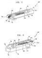
- the device for stopping with shock absorption and stabilize sliding doors and shutters of the present invention is indicated as a whole as 10 in figure 1 and is destined to cooperate with a carriage 12 fixed to door or shutter, the latter schematically indicated as 14.
- Said device is inserted and fixed in a section bar or track 16, known in the art, wherein rollers 18 uf carriage 12 run; section bar 16 at its inferior side is provided with a central slot 20 running along its length, wherefrom the lower part of carriage 12 protrudes, constituted by a profiled frame 22 destined to be fixed to door or shutter 14.
- Said latter in the preferred embodiment shown in figure 1, is provided with a perimetral metal section bar structure, e.g. aluminium, wherein at least section bar 24 which represents its horizontally developed superior part defines a house 26 wherein the profiled frame 22 of carriage 12 will be set and fixed in a known manner.
- Carriage 12 is generally known in its overall structure, i.e.
- Device 10 comprises a base support 30, built of a suitable material, preferably nylon added with glass fibres, constituted by an essentially parallelepiped solid piece, whereon two opposed and aligned arms 32, 34 are fixed, protruding from base 30 on the front side facing carriage 12.
- Said arms are fixed on support base unit 30 by means of rivets 36 or the like and on the anterior free end bear a boss or cam 38, provided on one face or on a part of its lateral surface with a profiled seat 40; the configuration of said seat 40 is so that it matches, at least partially or temporarily, with the profile of strike element 12' of carriage 12'.
- seat 40 defines a cavity with substantially semicircular shape and horizontally extended, complementary to strike element 12' defining a substantially semicircular configuration.
- Boss or cam 38 is hinged on arms 32 and 34 by means of through stud or pin 42 running through the boss itself about at the middle point of its longitudinal development; a further through stud, in case two opposed and aligned studs 44, are inserted at the sides of boss 38 before stud 42 and protrude from the stud itself beyond arms 32 and 34, creating coupling points for end points of the same number of spiral springs 46, of whom just one is shown in the figures. The opposite end point of said springs 46 engages a projection 48, protruding from each arm 32, 34 at the middle point of their length.
- Said elements 50 protrude from the base of support base unit 30 on the anterior side facing carriage 12 and are constituted, for example, by rubber or elastomeric material elements, in case suppurted by springs, partially inserted in the base unit itself.
- said elements 50 are constituted by one, preferably two close oil, air or silicone, pistons, of the type known for example, in the market as Smove, from the company Salice; said pistons, substantially cylindrical, are inserted into seats created onto the support base 30 wherefrom they protrude at the front part with their retractile stem, schematically shown as 50' in figures 1, 2 and 3.
- Stem or stems 50' of pistons 50 progressively withdraw as they are struck by element 12' of carriage 12, as schematically shown in figures 3 and 4 and described in detail as follows with reference to the functioning of device 10 of the present invention.
- Said device is fixed within section bar 16 by means of screws 52 or the like, vertically running through support base 30 wherefrom they protrude at the superior part for striking the internal surface of the superior side or base of the section bar itself; head of screws 52 is properly dimensioned in order to strike the opposite inferior base of said section bar, from central slot 20 through which screws run.
- Carriage 12 is stabilized into section bar 24 by means of known elements, e.g.
- carriage 12 On functioning, i.e. during door or shutter closing, carriage 12 progressively gets closed to device 10 sliding with rollers or guide shoes 18 on section bar 16, until it gets in contact with its boss or cam 38 by means of relative strike element 12'.
- said boss is positioned according to the configuration shown in figure 2, i.e. with profiled seat 40 basically facing downward in order to match the profile of said element 12'.
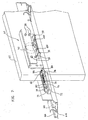
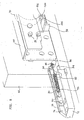
- FIG. 5 schematically represent the device of the present invention according to an alternative and simplified embodiment. Said device, indicated as a whole as 10', is destined also in this case to cooperate with carriage 60, fixed in a known manner to the door or shutter schematically indicated as 62 in figure 7.
- section bar or track 64 which preferably comprises two close sliding guides 66, 68 for one or more rollers 70 or the like belonging to the same number of carriages 60; embodiment of figure 7, wherein section bar 64 comprises the above mentioned sliding seats 66, 68, features two devices 10', each seated and constrained to one of said seats 66, 68.
- a solution of this kind is suitable for double shutters, i.e. external and internal shutter, both sliding along section bar 64 by means of respective carriages 60.
- section bar 64 will obviously feature just one sliding seat 66 or 68 where is set just one sliding device 10'.
- Said latter shown in detail in figures 5 and 6 comprises, likewise previously described device 10, a support base unit 72, metal made, nylon with class fibres and other suitable material; support base unit 72 is constituted by a parallelepiped solid piece, and from the superior side of it, shoulder 74 protrudes, for example from one of the edges corresponding to one of the longest sides, whose shape is bar like with limited width.
- Said shoulder 74 can be made solid with base support unit 72, i.e. can be reported and fixed to it in one known manner.
- Shoulder 74 represents the support for a couple of opposed and aligned arms 76, 78, like arms 32, 34 of the previously mentioned embodiment and constituted by metal plates.
- Arms 76, 78 are fixed at their rear end parts to the opposed sides of shoulder 74 by means of rivets 80 or similar means; the opposed anterior end part of arms 76, 78 bears a profiled boss or cam 82, hinged on arms themselves by means of a through pin 84.
- Boss 82 is shown as example configuration as an arched lozenge whose anterior extremity protrudes from arms 76, 78 and creates a nozzle 86.
- a pin 88 is transversely inserted into nozzle 86, in a position close to the anterior end part of arms 76, 78; said pin protrudes from opposed sides of nozzle 86 of cam 82 and creates the coupling points for the end parts of the same number of spiral springs 90.
- springs 90 The opposed end part of springs 90 is hooked to a prominence 93 protruding from each arm 76 and 78, close to rivets 80 constraining them to shoulder 74 of base unit 72.
- Springs 46 keep in tension cam or profiled boss 82 which is pivoted on pin 84 and is therefore, in theory, free to rotate according to a wide arch of circumference; this rotation, further, is limited as a function of the configuration of a plate 92 whose description will came later on, fixed on carriage 60. From the anterior side facing nozzle 86 of support base unit 72 retractile stem 94 of oil piston 50' protrudes in the previously described embodiment.
- Plate 92 is brought by carriage 60, known in itself, whereon is fixed by means of screws 95 or the like displaced on vertical wall 96 of the plate itself.
- Said wall 96 is expended overhanging and perpendicularly outward, i.e. according to the direction opposed to shutter 62, creates a plane surface and comprises, at least at one end point, a folding 98 destined to be struck by nozzle 86 of cam 82 and by stem 94 of the oil piston, as will be better explained later.
- a window 100 is created in order to house nozzle 86.
- folding 98 and window 100 are present on both sides of plate 92, so that carriage 60 can be applied both to shutters with right or left closing.
- the device of the present invention in both the embodiments described, allows to close sliding doors and shutters in a gradual manner, precise, without undesirable collisions, guiding the closing element with a shock absorption effect avoiding noises and, above all, possible tear of sliding elements as a consequence of violent collisions.
- the above described solutions could anyway comprise also the possibility to utilise magnetic components, i.e. cam or boss 38-86 and/or strike element 12'-98, in order to ease reciprocal cooperation before and during the intervention of the pistons destined to perform the shock absorption.
- device 10 or 10' of the present invention can be applied also on the opposite side, i.e.
Claims (9)
- Dispositif (10 - 10') d'arrêt de portes et volets coulissants (14 - 62), avec absorption de chocs et stabilisation, coopérant avec un chariot (12 - 60) fixé auxdites portes et auxdits volets et pourvu de rouleaux et de patins de guidage (18 - 70),
comprenant une unité de base porteuse (30 - 72) incluant une came ou un bossage (38 - 82) maintenu en tension par au moins un ressort (46 - 90), un moyen (50 - 51) élastique et absorbeur de chocs faisant dépassant partiellement de ladite unité de base sur le côté tourné vers ledit chariot (12 - 60),
caractérisé en ce que ladite unité de base porteuse (30 - 72) comprend deux bras opposés et alignés (32 - 34), (76 - 78) dépassant du côté antérieur tourné vers le chariot (12 - 60) et portant ladite came ou ledit bossage au point d'extrémité libre, ladite unité de base (38 - 72) intégrant de plus ledit moyen (50 - 51) élastique et absorbeur de chocs, et en ce que
ledit bossage ou ladite came (38) est monté à charnière sur lesdits bras (32, 34) au moyen d'une broche (42) traversant le bossage près de son point intermédiaire, et sa surface latérale comprend un logement profilé (40) dont la configuration est complémentaire de celle d'un élément d'attaque (12') solidaire du côté antérieur dudit chariot (12) tourné vers le bossage, et en ce que
les côtés opposés dudit bossage (38) portent chacun un goujon (44) dépassant au delà desdits bras (32 - 34) et ces goujons représentent des points d'accouplement pour les parties d'extrémité dudit ou de chacun desdits ressort(s) (46) dont l'extrémité opposée est en prise avec une saillie (48) dépassant de chacun desdits bras (32 - 34) qui sont constitués par des plaques métalliques fixées à ladite unité de base porteuse (30) au moyen de rivets (36) ou similaires. - Dispositif selon la revendication 1, caractérisé en ce que ledit bossage (82) porte un embout (86), monté à charnière sur lesdits bras (76 - 78) au moyen d'une broche (84) et attaquant un rebord (98) fixé sur le chariot (60) au moyen de vis (95) réparties le long d'une paroi verticale (96) de ladite plaque, ladite paroi (96) se prolongeant en surplomb et perpendiculairement vers l'extérieur et comprenant ledit rebord (98).
- Dispositif selon la revendication 2, caractérisé en ce qu'un rebord (98) est formé sur des côtés opposés de ladite plaque (92), et une fenêtre (100) est formée près de chacun d'eux, afin de loger ledit embout (86) de ladite came ou dudit bossage (82).
- Dispositif selon l'une des revendications 1 à 3, caractérisé en ce que lesdits rouleaux (18) dudit chariot (12) sont connectés à un support (28) et sont répartis sur un profilé (16) dans le côté inférieur de laquelle une fente centrale (20) est ménagée dans le sens de la longueur, ledit chariot (12) comprenant un cadre (22) fixé sur la porte ou le volet (14).
- Dispositif selon l'une quelconque des revendications précédentes, caractérisé en ce que ledit moyen (50 - 51) élastique et absorbeur de chocs intégré sur la base porteuse (30 - 72) comprend un ou plusieurs vérins hydrauliques, pneumatiques ou au silicone, dont la tige dépasse dudit côté avant de ladite unité de base et est attaquée par un élément (12') du chariot (12) ou par le rebord (98) de la paroi verticale (96) de la plaque (92).
- Dispositif selon l'une quelconque des revendications précédentes, caractérisé en ce que ledit logement profilé (40) de bossage ou de came (38) définit une cavité de configuration sensiblement semi-circulaire s'étendant horizontalement, et la configuration dudit élément (12') du chariot (12) est semi-circulaire sensiblement complémentaire.
- Dispositif selon l'une quelconque des revendications précédentes, caractérisé en ce que ladite porte ou ledit volet (14) associé audit dispositif comprend un cadre périphérique formé par des profilés parmi lesquels au moins le plus haut (24) - qui constitue sa partie supérieure qui se développe horizontalement - définit un logement (26) pour loger et fixer ledit cadre (22) du chariot (12), ledit dispositif étant fixé intérieurement audit profilé (16) au moyen de vis (52).
- Dispositif selon l'une quelconque des revendications précédentes, caractérisé en ce qu'il est déplacé et stabilisé dans un profilé (64) qui comprend au moins un guidage coulissant (66) et/ou (68) pour ledit ou lesdits chariot(s) (60), ladite unité de base porteuse (72) étant d'une configuration sensiblement parallélépipédique et comprenant un épaulement (74) qui se développe depuis son côté supérieur le long de l'un des bords correspondant à l'un des longs côtés.
- Dispositif selon l'une quelconque des revendications précédentes, caractérisé en ce que ledit embout (86) de came ou de bossage (82) comprend une broche (88) s'étendant transversalement et dépassant depuis chacun des côtés opposés, où est attaché sous tension un point d'extrémité dudit ou desdits ressort(s) (90) qui est ou sont fixé(s) à l'autre point d'extrémité à une ou plusieurs saillies (93) dépassant desdits bras (76 - 78).
Applications Claiming Priority (1)
| Application Number | Priority Date | Filing Date | Title |
|---|---|---|---|
| IT000445U ITMI20040445U1 (it) | 2004-09-28 | 2004-09-28 | Dispositivo per l'arresto ammortizzato e la stabilizzazione di porte e ante scorrevoli |
Publications (3)
| Publication Number | Publication Date |
|---|---|
| EP1640537A2 EP1640537A2 (fr) | 2006-03-29 |
| EP1640537A3 EP1640537A3 (fr) | 2007-02-14 |
| EP1640537B1 true EP1640537B1 (fr) | 2008-01-09 |
Family
ID=35466521
Family Applications (1)
| Application Number | Title | Priority Date | Filing Date |
|---|---|---|---|
| EP05019200A Not-in-force EP1640537B1 (fr) | 2004-09-28 | 2005-09-05 | Dispositif d'arrêt amortissant et stabilisant pour portes et volets coulissantes |
Country Status (4)
| Country | Link |
|---|---|
| EP (1) | EP1640537B1 (fr) |
| AT (1) | ATE383482T1 (fr) |
| DE (1) | DE602005004216D1 (fr) |
| IT (1) | ITMI20040445U1 (fr) |
Cited By (1)
| Publication number | Priority date | Publication date | Assignee | Title |
|---|---|---|---|---|
| RU2667137C2 (ru) * | 2014-01-23 | 2018-09-14 | Кобленц С.п.А. | Стопорное и демпфирующее устройство для узлов каретки раздвижных дверей для зданий или мебели и подобных им |
Families Citing this family (11)
| Publication number | Priority date | Publication date | Assignee | Title |
|---|---|---|---|---|
| FR2906824B1 (fr) | 2006-10-09 | 2008-12-26 | Roger Mondelin Sas Soc Par Act | Dispositif support de butees pour la pose de plaques de platre de largeur variable avec des appareils de levage et de manutention desdites plaques |
| FR2915225B1 (fr) * | 2007-04-18 | 2012-06-01 | Fermod | Serrure coulissante |
| FR2923251A1 (fr) | 2007-11-05 | 2009-05-08 | Adler Sa Sa | Armoire formant vitrine avec verrouillage pour au moins une vitre coulissante |
| FR2952107B1 (fr) * | 2009-11-02 | 2011-12-16 | Adler Sas | Armoire formant vitrine avec verrouillage pour au moins une vitre coulissante |
| ITRN20100003A1 (it) * | 2010-02-03 | 2010-05-05 | Giesse Plast S R L | Anta per porte scorrevoli a scomparsa e relativa porta |
| IT1402039B1 (it) * | 2010-10-15 | 2013-08-28 | Caimi Export Spa | Dispositivo di scorrimento per elementi scorrevoli di mobili |
| FR3001754B1 (fr) | 2013-02-07 | 2015-05-29 | Saint Gobain Seva | Dispositif de blocage d'un panneau mobile en translation et dispositif d'occultation comportant un tel dispositif. |
| DE102013219484B3 (de) * | 2013-09-27 | 2015-01-22 | Geze Gmbh | Einzugsvorrichtung |
| JP6344708B2 (ja) * | 2013-09-30 | 2018-06-20 | パナソニックIpマネジメント株式会社 | 引戸装置 |
| IT201600078974A1 (it) | 2016-07-27 | 2018-01-27 | Terno Scorrevoli S P A Unipersonale | Dispositivo frenante a bilanciere per porte e per ante scorrevoli di mobili |
| IT201900000421A1 (it) * | 2019-01-10 | 2020-07-10 | Composad Srl | Struttura ad ante scorrevoli per armadi. |
Family Cites Families (4)
| Publication number | Priority date | Publication date | Assignee | Title |
|---|---|---|---|---|
| CH657415A5 (en) * | 1982-09-01 | 1986-08-29 | Karl Haab | Sliding door with a holding device |
| FR2763026B1 (fr) * | 1997-05-07 | 1999-06-18 | Renault | Dispositif de guidage et d'arret d'une porte coulissante, en particulier une porte laterale coulissante d'un vehicule automobile |
| IL137708A0 (en) * | 1999-03-16 | 2001-10-31 | Hawa Ag | Buffer device |
| DE202004001068U1 (de) * | 2004-01-23 | 2004-03-18 | Hettich-Heinze Gmbh & Co. Kg | Durch Einklipsen montierbares Laufwerkgehäuse für Schiebe- und Faltschiebetüren |
-
2004
- 2004-09-28 IT IT000445U patent/ITMI20040445U1/it unknown
-
2005
- 2005-09-05 DE DE602005004216T patent/DE602005004216D1/de active Active
- 2005-09-05 AT AT05019200T patent/ATE383482T1/de not_active IP Right Cessation
- 2005-09-05 EP EP05019200A patent/EP1640537B1/fr not_active Not-in-force
Cited By (1)
| Publication number | Priority date | Publication date | Assignee | Title |
|---|---|---|---|---|
| RU2667137C2 (ru) * | 2014-01-23 | 2018-09-14 | Кобленц С.п.А. | Стопорное и демпфирующее устройство для узлов каретки раздвижных дверей для зданий или мебели и подобных им |
Also Published As
| Publication number | Publication date |
|---|---|
| EP1640537A3 (fr) | 2007-02-14 |
| ATE383482T1 (de) | 2008-01-15 |
| ITMI20040445U1 (it) | 2004-12-28 |
| EP1640537A2 (fr) | 2006-03-29 |
| DE602005004216D1 (de) | 2008-02-21 |
Similar Documents
| Publication | Publication Date | Title |
|---|---|---|
| EP1640537B1 (fr) | Dispositif d'arrêt amortissant et stabilisant pour portes et volets coulissantes | |
| US11447997B2 (en) | Damping or return device for sliding door leaves or for drawers | |
| US8950116B2 (en) | Sliding door arrangement | |
| JP2005023615A (ja) | 引戸の戸閉装置 | |
| KR101127639B1 (ko) | 개폐구용 완충장치 | |
| EP2372066A1 (fr) | Agencement de porte coulissante | |
| EP2128368A1 (fr) | Dispositif d'arrêt pour panneaux de portes coulissantes | |
| KR101718484B1 (ko) | 슬라이딩 도어용 스토퍼 | |
| US20160076293A1 (en) | System and device for soft closing | |
| KR20080007538A (ko) | 도어용 경첩 | |
| KR20100120007A (ko) | 회동식 창호용 스테이바 | |
| CN108756567B (zh) | 一种移门缓冲器 | |
| KR101262765B1 (ko) | 창호의 안전 닫힘장치 | |
| KR101178316B1 (ko) | 미닫이 문의 닫힘 충격 완충장치 | |
| KR20190072202A (ko) | 창호의 완충부 장착 구조체 및 이를 포함한 창호 | |
| JP5380642B2 (ja) | シャッタ | |
| KR200406154Y1 (ko) | 슬라이딩 도어와 셔터들을 충격 흡수 및 안정화와 함께정지시키는 장치 | |
| JP4888070B2 (ja) | 折戸開閉機構における指詰防止装置 | |
| JP5103094B2 (ja) | 引戸装置 | |
| GB2428734A (en) | Bolt release device comprising release lever with depending horns | |
| KR20170001897U (ko) | 슬라이딩 도어용 가이드 프레임 | |
| JP2021134606A (ja) | 引き戸の制動装置 | |
| JP2020056235A (ja) | アームストッパー | |
| EP4141205A1 (fr) | Serrure avec fermeture automatique et ouverture par poussée | |
| KR20180079062A (ko) | 충격을 방지하는 반자동 현수식 교실출입문 |
Legal Events
| Date | Code | Title | Description |
|---|---|---|---|
| PUAI | Public reference made under article 153(3) epc to a published international application that has entered the european phase |
Free format text: ORIGINAL CODE: 0009012 |
|
| AK | Designated contracting states |
Kind code of ref document: A2 Designated state(s): AT BE BG CH CY CZ DE DK EE ES FI FR GB GR HU IE IS IT LI LT LU LV MC NL PL PT RO SE SI SK TR |
|
| AX | Request for extension of the european patent |
Extension state: AL BA HR MK YU |
|
| PUAL | Search report despatched |
Free format text: ORIGINAL CODE: 0009013 |
|
| AK | Designated contracting states |
Kind code of ref document: A3 Designated state(s): AT BE BG CH CY CZ DE DK EE ES FI FR GB GR HU IE IS IT LI LT LU LV MC NL PL PT RO SE SI SK TR |
|
| AX | Request for extension of the european patent |
Extension state: AL BA HR MK YU |
|
| RAP1 | Party data changed (applicant data changed or rights of an application transferred) |
Owner name: TERNO SCORREVOLI S.R.L. |
|
| 17P | Request for examination filed |
Effective date: 20070622 |
|
| GRAP | Despatch of communication of intention to grant a patent |
Free format text: ORIGINAL CODE: EPIDOSNIGR1 |
|
| AKX | Designation fees paid |
Designated state(s): AT BE BG CH CY CZ DE DK EE ES FI FR GB GR HU IE IS IT LI LT LU LV MC NL PL PT RO SE SI SK TR |
|
| GRAS | Grant fee paid |
Free format text: ORIGINAL CODE: EPIDOSNIGR3 |
|
| GRAA | (expected) grant |
Free format text: ORIGINAL CODE: 0009210 |
|
| AK | Designated contracting states |
Kind code of ref document: B1 Designated state(s): AT BE BG CH CY CZ DE DK EE ES FI FR GB GR HU IE IS IT LI LT LU LV MC NL PL PT RO SE SI SK TR |
|
| REG | Reference to a national code |
Ref country code: GB Ref legal event code: FG4D |
|
| REG | Reference to a national code |
Ref country code: CH Ref legal event code: EP |
|
| REG | Reference to a national code |
Ref country code: IE Ref legal event code: FG4D |
|
| REF | Corresponds to: |
Ref document number: 602005004216 Country of ref document: DE Date of ref document: 20080221 Kind code of ref document: P |
|
| PG25 | Lapsed in a contracting state [announced via postgrant information from national office to epo] |
Ref country code: SI Free format text: LAPSE BECAUSE OF FAILURE TO SUBMIT A TRANSLATION OF THE DESCRIPTION OR TO PAY THE FEE WITHIN THE PRESCRIBED TIME-LIMIT Effective date: 20080109 Ref country code: NL Free format text: LAPSE BECAUSE OF FAILURE TO SUBMIT A TRANSLATION OF THE DESCRIPTION OR TO PAY THE FEE WITHIN THE PRESCRIBED TIME-LIMIT Effective date: 20080109 |
|
| NLV1 | Nl: lapsed or annulled due to failure to fulfill the requirements of art. 29p and 29m of the patents act | ||
| PG25 | Lapsed in a contracting state [announced via postgrant information from national office to epo] |
Ref country code: FI Free format text: LAPSE BECAUSE OF FAILURE TO SUBMIT A TRANSLATION OF THE DESCRIPTION OR TO PAY THE FEE WITHIN THE PRESCRIBED TIME-LIMIT Effective date: 20080109 Ref country code: ES Free format text: LAPSE BECAUSE OF FAILURE TO SUBMIT A TRANSLATION OF THE DESCRIPTION OR TO PAY THE FEE WITHIN THE PRESCRIBED TIME-LIMIT Effective date: 20080420 Ref country code: LT Free format text: LAPSE BECAUSE OF FAILURE TO SUBMIT A TRANSLATION OF THE DESCRIPTION OR TO PAY THE FEE WITHIN THE PRESCRIBED TIME-LIMIT Effective date: 20080109 Ref country code: CH Free format text: LAPSE BECAUSE OF FAILURE TO SUBMIT A TRANSLATION OF THE DESCRIPTION OR TO PAY THE FEE WITHIN THE PRESCRIBED TIME-LIMIT Effective date: 20080109 Ref country code: LI Free format text: LAPSE BECAUSE OF FAILURE TO SUBMIT A TRANSLATION OF THE DESCRIPTION OR TO PAY THE FEE WITHIN THE PRESCRIBED TIME-LIMIT Effective date: 20080109 Ref country code: IS Free format text: LAPSE BECAUSE OF FAILURE TO SUBMIT A TRANSLATION OF THE DESCRIPTION OR TO PAY THE FEE WITHIN THE PRESCRIBED TIME-LIMIT Effective date: 20080509 |
|
| REG | Reference to a national code |
Ref country code: CH Ref legal event code: PL |
|
| PG25 | Lapsed in a contracting state [announced via postgrant information from national office to epo] |
Ref country code: AT Free format text: LAPSE BECAUSE OF FAILURE TO SUBMIT A TRANSLATION OF THE DESCRIPTION OR TO PAY THE FEE WITHIN THE PRESCRIBED TIME-LIMIT Effective date: 20080109 Ref country code: BG Free format text: LAPSE BECAUSE OF FAILURE TO SUBMIT A TRANSLATION OF THE DESCRIPTION OR TO PAY THE FEE WITHIN THE PRESCRIBED TIME-LIMIT Effective date: 20080409 |
|
| PG25 | Lapsed in a contracting state [announced via postgrant information from national office to epo] |
Ref country code: PT Free format text: LAPSE BECAUSE OF FAILURE TO SUBMIT A TRANSLATION OF THE DESCRIPTION OR TO PAY THE FEE WITHIN THE PRESCRIBED TIME-LIMIT Effective date: 20080609 Ref country code: BE Free format text: LAPSE BECAUSE OF FAILURE TO SUBMIT A TRANSLATION OF THE DESCRIPTION OR TO PAY THE FEE WITHIN THE PRESCRIBED TIME-LIMIT Effective date: 20080109 Ref country code: PL Free format text: LAPSE BECAUSE OF FAILURE TO SUBMIT A TRANSLATION OF THE DESCRIPTION OR TO PAY THE FEE WITHIN THE PRESCRIBED TIME-LIMIT Effective date: 20080109 Ref country code: LV Free format text: LAPSE BECAUSE OF FAILURE TO SUBMIT A TRANSLATION OF THE DESCRIPTION OR TO PAY THE FEE WITHIN THE PRESCRIBED TIME-LIMIT Effective date: 20080109 |
|
| EN | Fr: translation not filed | ||
| PG25 | Lapsed in a contracting state [announced via postgrant information from national office to epo] |
Ref country code: CZ Free format text: LAPSE BECAUSE OF FAILURE TO SUBMIT A TRANSLATION OF THE DESCRIPTION OR TO PAY THE FEE WITHIN THE PRESCRIBED TIME-LIMIT Effective date: 20080109 Ref country code: DK Free format text: LAPSE BECAUSE OF FAILURE TO SUBMIT A TRANSLATION OF THE DESCRIPTION OR TO PAY THE FEE WITHIN THE PRESCRIBED TIME-LIMIT Effective date: 20080109 Ref country code: SE Free format text: LAPSE BECAUSE OF FAILURE TO SUBMIT A TRANSLATION OF THE DESCRIPTION OR TO PAY THE FEE WITHIN THE PRESCRIBED TIME-LIMIT Effective date: 20080409 Ref country code: SK Free format text: LAPSE BECAUSE OF FAILURE TO SUBMIT A TRANSLATION OF THE DESCRIPTION OR TO PAY THE FEE WITHIN THE PRESCRIBED TIME-LIMIT Effective date: 20080109 |
|
| PLBE | No opposition filed within time limit |
Free format text: ORIGINAL CODE: 0009261 |
|
| STAA | Information on the status of an ep patent application or granted ep patent |
Free format text: STATUS: NO OPPOSITION FILED WITHIN TIME LIMIT |
|
| PG25 | Lapsed in a contracting state [announced via postgrant information from national office to epo] |
Ref country code: RO Free format text: LAPSE BECAUSE OF FAILURE TO SUBMIT A TRANSLATION OF THE DESCRIPTION OR TO PAY THE FEE WITHIN THE PRESCRIBED TIME-LIMIT Effective date: 20080109 |
|
| 26N | No opposition filed |
Effective date: 20081010 |
|
| PG25 | Lapsed in a contracting state [announced via postgrant information from national office to epo] |
Ref country code: DE Free format text: LAPSE BECAUSE OF FAILURE TO SUBMIT A TRANSLATION OF THE DESCRIPTION OR TO PAY THE FEE WITHIN THE PRESCRIBED TIME-LIMIT Effective date: 20080410 |
|
| PG25 | Lapsed in a contracting state [announced via postgrant information from national office to epo] |
Ref country code: FR Free format text: LAPSE BECAUSE OF FAILURE TO SUBMIT A TRANSLATION OF THE DESCRIPTION OR TO PAY THE FEE WITHIN THE PRESCRIBED TIME-LIMIT Effective date: 20081031 Ref country code: MC Free format text: LAPSE BECAUSE OF NON-PAYMENT OF DUE FEES Effective date: 20080930 Ref country code: EE Free format text: LAPSE BECAUSE OF FAILURE TO SUBMIT A TRANSLATION OF THE DESCRIPTION OR TO PAY THE FEE WITHIN THE PRESCRIBED TIME-LIMIT Effective date: 20080109 |
|
| PG25 | Lapsed in a contracting state [announced via postgrant information from national office to epo] |
Ref country code: IE Free format text: LAPSE BECAUSE OF NON-PAYMENT OF DUE FEES Effective date: 20080905 Ref country code: CY Free format text: LAPSE BECAUSE OF FAILURE TO SUBMIT A TRANSLATION OF THE DESCRIPTION OR TO PAY THE FEE WITHIN THE PRESCRIBED TIME-LIMIT Effective date: 20080109 |
|
| GBPC | Gb: european patent ceased through non-payment of renewal fee |
Effective date: 20090905 |
|
| PG25 | Lapsed in a contracting state [announced via postgrant information from national office to epo] |
Ref country code: LU Free format text: LAPSE BECAUSE OF NON-PAYMENT OF DUE FEES Effective date: 20080905 Ref country code: HU Free format text: LAPSE BECAUSE OF FAILURE TO SUBMIT A TRANSLATION OF THE DESCRIPTION OR TO PAY THE FEE WITHIN THE PRESCRIBED TIME-LIMIT Effective date: 20080710 |
|
| PG25 | Lapsed in a contracting state [announced via postgrant information from national office to epo] |
Ref country code: TR Free format text: LAPSE BECAUSE OF FAILURE TO SUBMIT A TRANSLATION OF THE DESCRIPTION OR TO PAY THE FEE WITHIN THE PRESCRIBED TIME-LIMIT Effective date: 20080109 |
|
| PG25 | Lapsed in a contracting state [announced via postgrant information from national office to epo] |
Ref country code: GR Free format text: LAPSE BECAUSE OF FAILURE TO SUBMIT A TRANSLATION OF THE DESCRIPTION OR TO PAY THE FEE WITHIN THE PRESCRIBED TIME-LIMIT Effective date: 20080410 |
|
| PG25 | Lapsed in a contracting state [announced via postgrant information from national office to epo] |
Ref country code: GB Free format text: LAPSE BECAUSE OF NON-PAYMENT OF DUE FEES Effective date: 20090905 |
|
| PGFP | Annual fee paid to national office [announced via postgrant information from national office to epo] |
Ref country code: IT Payment date: 20130930 Year of fee payment: 9 |
|
| PG25 | Lapsed in a contracting state [announced via postgrant information from national office to epo] |
Ref country code: IT Free format text: LAPSE BECAUSE OF NON-PAYMENT OF DUE FEES Effective date: 20140905 |