EP1640537B1 - Device for stopping with shock absorption and stabilizing sliding doors and shutters - Google Patents
Device for stopping with shock absorption and stabilizing sliding doors and shutters Download PDFInfo
- Publication number
- EP1640537B1 EP1640537B1 EP05019200A EP05019200A EP1640537B1 EP 1640537 B1 EP1640537 B1 EP 1640537B1 EP 05019200 A EP05019200 A EP 05019200A EP 05019200 A EP05019200 A EP 05019200A EP 1640537 B1 EP1640537 B1 EP 1640537B1
- Authority
- EP
- European Patent Office
- Prior art keywords
- carriage
- boss
- base unit
- cam
- arms
- Prior art date
- Legal status (The legal status is an assumption and is not a legal conclusion. Google has not performed a legal analysis and makes no representation as to the accuracy of the status listed.)
- Not-in-force
Links
Images


Classifications
-
- E—FIXED CONSTRUCTIONS
- E05—LOCKS; KEYS; WINDOW OR DOOR FITTINGS; SAFES
- E05B—LOCKS; ACCESSORIES THEREFOR; HANDCUFFS
- E05B65/00—Locks or fastenings for special use
- E05B65/08—Locks or fastenings for special use for sliding wings
- E05B65/0811—Locks or fastenings for special use for sliding wings the bolts pivoting about an axis perpendicular to the wings
- E05B65/0829—Locks or fastenings for special use for sliding wings the bolts pivoting about an axis perpendicular to the wings mounted on the slide guide, e.g. the rail
-
- E—FIXED CONSTRUCTIONS
- E05—LOCKS; KEYS; WINDOW OR DOOR FITTINGS; SAFES
- E05F—DEVICES FOR MOVING WINGS INTO OPEN OR CLOSED POSITION; CHECKS FOR WINGS; WING FITTINGS NOT OTHERWISE PROVIDED FOR, CONCERNED WITH THE FUNCTIONING OF THE WING
- E05F5/00—Braking devices, e.g. checks; Stops; Buffers
- E05F5/02—Braking devices, e.g. checks; Stops; Buffers specially for preventing the slamming of swinging wings during final closing movement, e.g. jamb stops
- E05F5/027—Braking devices, e.g. checks; Stops; Buffers specially for preventing the slamming of swinging wings during final closing movement, e.g. jamb stops with closing action
-
- E—FIXED CONSTRUCTIONS
- E05—LOCKS; KEYS; WINDOW OR DOOR FITTINGS; SAFES
- E05B—LOCKS; ACCESSORIES THEREFOR; HANDCUFFS
- E05B17/00—Accessories in connection with locks
- E05B17/0045—Silencing devices; Noise reduction
-
- E—FIXED CONSTRUCTIONS
- E05—LOCKS; KEYS; WINDOW OR DOOR FITTINGS; SAFES
- E05F—DEVICES FOR MOVING WINGS INTO OPEN OR CLOSED POSITION; CHECKS FOR WINGS; WING FITTINGS NOT OTHERWISE PROVIDED FOR, CONCERNED WITH THE FUNCTIONING OF THE WING
- E05F5/00—Braking devices, e.g. checks; Stops; Buffers
- E05F5/003—Braking devices, e.g. checks; Stops; Buffers for sliding wings
-
- E—FIXED CONSTRUCTIONS
- E05—LOCKS; KEYS; WINDOW OR DOOR FITTINGS; SAFES
- E05Y—INDEXING SCHEME RELATING TO HINGES OR OTHER SUSPENSION DEVICES FOR DOORS, WINDOWS OR WINGS AND DEVICES FOR MOVING WINGS INTO OPEN OR CLOSED POSITION, CHECKS FOR WINGS AND WING FITTINGS NOT OTHERWISE PROVIDED FOR, CONCERNED WITH THE FUNCTIONING OF THE WING
- E05Y2800/00—Details, accessories and auxiliary operations not otherwise provided for
- E05Y2800/15—Applicability
- E05Y2800/17—Universally applicable
- E05Y2800/172—Universally applicable on different wing or frame locations
- E05Y2800/174—Universally applicable on different wing or frame locations on the left or right side
-
- E—FIXED CONSTRUCTIONS
- E05—LOCKS; KEYS; WINDOW OR DOOR FITTINGS; SAFES
- E05Y—INDEXING SCHEME RELATING TO HINGES OR OTHER SUSPENSION DEVICES FOR DOORS, WINDOWS OR WINGS AND DEVICES FOR MOVING WINGS INTO OPEN OR CLOSED POSITION, CHECKS FOR WINGS AND WING FITTINGS NOT OTHERWISE PROVIDED FOR, CONCERNED WITH THE FUNCTIONING OF THE WING
- E05Y2900/00—Application of doors, windows, wings or fittings thereof
- E05Y2900/10—Application of doors, windows, wings or fittings thereof for buildings or parts thereof
- E05Y2900/13—Application of doors, windows, wings or fittings thereof for buildings or parts thereof characterised by the type of wing
- E05Y2900/132—Doors
-
- E—FIXED CONSTRUCTIONS
- E05—LOCKS; KEYS; WINDOW OR DOOR FITTINGS; SAFES
- E05Y—INDEXING SCHEME RELATING TO HINGES OR OTHER SUSPENSION DEVICES FOR DOORS, WINDOWS OR WINGS AND DEVICES FOR MOVING WINGS INTO OPEN OR CLOSED POSITION, CHECKS FOR WINGS AND WING FITTINGS NOT OTHERWISE PROVIDED FOR, CONCERNED WITH THE FUNCTIONING OF THE WING
- E05Y2900/00—Application of doors, windows, wings or fittings thereof
- E05Y2900/10—Application of doors, windows, wings or fittings thereof for buildings or parts thereof
- E05Y2900/13—Application of doors, windows, wings or fittings thereof for buildings or parts thereof characterised by the type of wing
- E05Y2900/146—Shutters
Abstract
Description
- The invention relates to a device for stopping with shock absorption and stabilizing sliding doors and shutters.
More particularly, the present invention relates to a device specifically suited for stopping and blocking after shutting, in a smooth and deadbeat manner, the excursion of panelling such as doors or shutters sliding on guides or tracks, respectively used for separating rooms or shielding furniture.
As known, especially in the real estate furnishing, both for living or different use, sliding doors between adjoining rooms have been used for long time. The shutter or shutters constituting the door, slide by means of carriages, featuring rollers or guide shoes, on a plane perpendicular to the floor. Same solution is used for shutters of a piece of furniture, and, in both cases, it allows to reduce the overall area used while opening.
This construction approach, further, gives advantages also in terms of aesthetic, provided that motion means are hidden and hinges and the like are kept out of sight.
The shutters constituting rooms' separation doors, but usually also the ones used in a big piece of furniture, are heavy, sometimes up to 150 kg; in these cases, the sliding carriages and their relative guides are suitably dimensioned, in order to guarantee a proper sliding motion despite the shutters' heavy weight. - Inconveniences, on the contrary, are found in relation to the means used to stop, especially during the closing phase, the excursion of the shutters at the end of the movement and to keep them in position.
- Known devices that, for this purpose, are associated to carriages, traditionally comprise one or more springs whose task is to realize a dragging effect to the closing shutter. These devices, nevertheless, are found suitable just for small and light shutters, and at any rate for drawers; in case of heavy shutters, on the contrary, these type of devices cannot guarantee a proper closing and stability, even if they are over-dimensioned, and above all, they are not suitable for stopping the excursion of the shutters themselves in a progressive manner or with shock absorption, as it would be desirable.
- As a matter of fact, if the closing is not helped, the shutters will violently hit at the end of the movement and bounce back, requiring a further and additional manual intervention for closing. In addition to the discomfort for the user, this situation creates noise and makes the components for the sliding and connected to the shutters, undergo a relevant shock which might lead, in time, to break, thus requiring complicated and expensive recovery interventions.
-
WO 00/55460 A - Object of the present invention is to avoid the above mentioned inconveniences.
- More particularly, the object of the present invention, is to provide a device for stopping with shock absorption and stabilize sliding doors and shutters in order to allow a precise closing of said doors and shutters in a smooth and gradual manner, preventing the door from rebounding to an open position when the door is slammed with force.
- Further object of the invention is to provide a device as previously defined, suitable for avoiding the sliding means fixed to the doors and shutters to be strongly stressed.
- Further object of the invention is to provide a device to be used to stop with shock absorption and stabilize sliding doors and shutters characterized by a high level of resilience and reliability over time, to be further easily and economically manufactured.
- These and other objects can be obtained by the device for stopping with shock absorption and stabilization sliding doors and shutters as claimed in claim 1.
- Construction and functional characteristics of the device for stopping with shock absorption and stabilize sliding doors and shutters of the present invention will be better understood in connection with the following explanation, which relates to the appended drawings describing a preferred but non limitative embodiment and wherein:
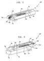
- figure 1 schematically represents, in a perspective view, the device
- of the present invention associated to a sliding carriage;
- figure 2 represents the same device on rest position, with approaching carriage;
- figure 3 represents the same device during the beginning of the carriage stopping and stabilizing phase;
- figure 4 represents the same device on the completed stabilization phase of the carriage, then door or shutter connected to the carriage itself.
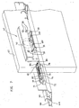
- figure 5 represents a schematic perspective view from the front side of the device according to an example alternative embodiment;
- figure 6 represents the device of the present figure on a schematic perspective view from the opposite rear side;
- figure 7 represents the same device of figures 5 and 6 connected to a sliding carriage;
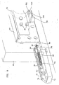
- figure 8 represents an enlarged detail of previous figure.
- With reference to the above figures, the device for stopping with shock absorption and stabilize sliding doors and shutters of the present invention is indicated as a whole as 10 in figure 1 and is destined to cooperate with a
carriage 12 fixed to door or shutter, the latter schematically indicated as 14. - Said device is inserted and fixed in a section bar or
track 16, known in the art, whereinrollers 18uf carriage 12 run;section bar 16 at its inferior side is provided with acentral slot 20 running along its length, wherefrom the lower part ofcarriage 12 protrudes, constituted by a profiledframe 22 destined to be fixed to door orshutter 14. Said latter, in the preferred embodiment shown in figure 1, is provided with a perimetral metal section bar structure, e.g. aluminium, wherein at leastsection bar 24 which represents its horizontally developed superior part defines ahouse 26 wherein the profiledframe 22 ofcarriage 12 will be set and fixed in a known manner. Carriage 12 is generally known in its overall structure, i.e.frame 22,rollers 18 and relative support, schematically shown as 28 and constituted by a plate or the like; further, provided thatcarriage 12 is destined to cooperate withdevice 10, the carriage itself is provided to additionally feature, on this purpose, a strike element 12', described in the following part.
Device 10 comprises abase support 30, built of a suitable material, preferably nylon added with glass fibres, constituted by an essentially parallelepiped solid piece, whereon two opposed and alignedarms base 30 on the frontside facing carriage 12.
Said arms, preferably made in metal plates, are fixed onsupport base unit 30 by means ofrivets 36 or the like and on the anterior free end bear a boss orcam 38, provided on one face or on a part of its lateral surface with a profiledseat 40; the configuration of saidseat 40 is so that it matches, at least partially or temporarily, with the profile of strike element 12' of carriage 12'. In the example embodiment relative to the figures,seat 40 defines a cavity with substantially semicircular shape and horizontally extended, complementary to strike element 12' defining a substantially semicircular configuration. Boss orcam 38 is hinged onarms pin 42 running through the boss itself about at the middle point of its longitudinal development; a further through stud, in case two opposed and alignedstuds 44, are inserted at the sides ofboss 38 beforestud 42 and protrude from the stud itself beyondarms spiral springs 46, of whom just one is shown in the figures. The opposite end point of saidsprings 46 engages aprojection 48, protruding from eacharm boss 38 in tension which, having a fulcrum on stud orpin 42, in theory is free to rotate, even though the presence offurther studs 44 protruding from it limits said rotation: as a matter of fact,studs 44 during the rotation of said boss strike the anterior side or head ofarms Boss 38, therefore, while rotating anticlockwise is limited and its movement is reduced to a partial balancing one. In the opposite direction, i.e. clockwise, said boss is equally limited by the presence of elasticshock absorption elements 50 described as follows. Saidelements 50 protrude from the base ofsupport base unit 30 on the anteriorside facing carriage 12 and are constituted, for example, by rubber or elastomeric material elements, in case suppurted by springs, partially inserted in the base unit itself. In the preferred embodiment shown in the figures, saidelements 50 are constituted by one, preferably two close oil, air or silicone, pistons, of the type known for example, in the market as Smove, from the company Salice; said pistons, substantially cylindrical, are inserted into seats created onto thesupport base 30 wherefrom they protrude at the front part with their retractile stem, schematically shown as 50' in figures 1, 2 and 3. Stem or stems 50' ofpistons 50 progressively withdraw as they are struck by element 12' ofcarriage 12, as schematically shown in figures 3 and 4 and described in detail as follows with reference to the functioning ofdevice 10 of the present invention. Said device is fixed withinsection bar 16 by means ofscrews 52 or the like, vertically running throughsupport base 30 wherefrom they protrude at the superior part for striking the internal surface of the superior side or base of the section bar itself; head ofscrews 52 is properly dimensioned in order to strike the opposite inferior base of said section bar, fromcentral slot 20 through which screws run.Carriage 12 is stabilized intosection bar 24 by means of known elements, e.g. self-threading screws (not shown) being inserted in one ormore holes 54 created on awing 56 of the carriage itself arid inserting intocorresponding seats 58 of said section bar. On functioning, i.e. during door or shutter closing,carriage 12 progressively gets closed todevice 10 sliding with rollers orguide shoes 18 onsection bar 16, until it gets in contact with its boss orcam 38 by means of relative strike element 12'. During this phase, said boss is positioned according to the configuration shown in figure 2, i.e. with profiledseat 40 basically facing downward in order to match the profile of said element 12'. Once the contact is reached, semi-cylindrical surface of element 12' appears to be precisely inserted into profiledseat 40 ofboss 38, which under the pushing effect positions itself according to a substantially horizontal manner, partially rotating clockwise, as in figure 3. At the same time, element 12' ofcarriage 12, coupled toboss 38, strikes elasticshock absorbing elements 50, advantageously constituted by above mentioned pistons, causing their stem 50' to withdraw. This withdrawal, progressive and with shock absorption, determines door or shutter to move with a gradual and free of deadbeat approach to the end position while closing; this end of movement is preferably defined by total withdrawal of stems 50', therefore by the contact between elements 12' and front part ofsupport base 30 ofdevice 10, as in figure 4. On the other side, for opening the door or shutter, it is sufficient to win the resistance ofspring 46 in order to let element 12' disengage fromboss 38, which can only make opposite movement, anticlockwise, and automatically moves to the position of figure 2, with stud/s 44 striking, on abutting, the anterior side or head ofarms pistons 50 previously withdrawn, stretch and move out again going back to the position of figures 2 and 3. Figures 5, 6, 7 and 8 schematically represent the device of the present invention according to an alternative and simplified embodiment.
Said device, indicated as a whole as 10', is destined also in this case to cooperate withcarriage 60, fixed in a known manner to the door or shutter schematically indicated as 62 in figure 7. Device 10' is inserted and fixed in a known manner onto section bar ortrack 64, known in the art, which preferably comprises two closesliding guides more rollers 70 or the like belonging to the same number ofcarriages 60; embodiment of figure 7, whereinsection bar 64 comprises the above mentionedsliding seats said seats section bar 64 by means ofrespective carriages 60. In case of single shutter,section bar 64 will obviously feature just one slidingseat device 10, asupport base unit 72, metal made, nylon with class fibres and other suitable material;support base unit 72 is constituted by a parallelepiped solid piece, and from the superior side of it,shoulder 74 protrudes, for example from one of the edges corresponding to one of the longest sides, whose shape is bar like with limited width.
Saidshoulder 74 can be made solid withbase support unit 72, i.e. can be reported and fixed to it in one known manner.Shoulder 74 represents the support for a couple of opposed and alignedarms arms Arms shoulder 74 by means ofrivets 80 or similar means; the opposed anterior end part ofarms cam 82, hinged on arms themselves by means of a throughpin 84. Boss 82 is shown as example configuration as an arched lozenge whose anterior extremity protrudes fromarms nozzle 86. Apin 88 is transversely inserted intonozzle 86, in a position close to the anterior end part ofarms nozzle 86 ofcam 82 and creates the coupling points for the end parts of the same number ofspiral springs 90. The opposed end part ofsprings 90 is hooked to aprominence 93 protruding from eacharm rivets 80 constraining them toshoulder 74 ofbase unit 72. Springs 46 keep in tension cam or profiledboss 82 which is pivoted onpin 84 and is therefore, in theory, free to rotate according to a wide arch of circumference; this rotation, further, is limited as a function of the configuration of a plate 92 whose description will came later on, fixed oncarriage 60.
From the anteriorside facing nozzle 86 ofsupport base unit 72retractile stem 94 of oil piston 50' protrudes in the previously described embodiment. Plate 92 is brought bycarriage 60, known in itself, whereon is fixed by means ofscrews 95 or the like displaced on vertical wall 96 of the plate itself. Said wall 96 is expended overhanging and perpendicularly outward, i.e. according to the direction opposed to shutter 62, creates a plane surface and comprises, at least at one end point, a folding 98 destined to be struck bynozzle 86 ofcam 82 and bystem 94 of the oil piston, as will be better explained later.
Along plate 92, closed to folding 98, awindow 100 is created in order to housenozzle 86. Preferably, folding 98 andwindow 100 are present on both sides of plate 92, so thatcarriage 60 can be applied both to shutters with right or left closing.
On functioning, whileshutter 62 is closingnozzle 86 ofcam 82 is struck by folding 98 of plate 92 which steers it downward in order to prepare it to hook towindow 100; at the same time, also stem 94 of the gas piston strikes folding 98 absorbing the shock of the shutter's excursion in themoment nozzle 86 folds further to get intowindow 100. Said further folding ofnozzle 86, puttingsprings 90 in tension, is imposed by one of the walls or edges ofwindow 100, in particular byrear edge 102 resulting farther away from folding 92.
On the contrary, requiring the opening of door or shutter 62 it is sufficient to win the resistance ofnozzle 86, therefore ofsprings 90, in order to have the nozzle itself to raise striking theopposite edge 104 ofwindow 100.
As can be seen by the above description, the advantages obtained by the invention are evident.
The device of the present invention, in both the embodiments described, allows to close sliding doors and shutters in a gradual manner, precise, without undesirable collisions, guiding the closing element with a shock absorption effect avoiding noises and, above all, possible tear of sliding elements as a consequence of violent collisions.
The above described solutions could anyway comprise also the possibility to utilise magnetic components, i.e. cam or boss 38-86 and/or strike element 12'-98, in order to ease reciprocal cooperation before and during the intervention of the pistons destined to perform the shock absorption.
It is to be further taken into account thatdevice 10 or 10' of the present invention can be applied also on the opposite side, i.e. during total opening of door or shutter, for example through the positioning ofcarriage independent carriages many devices 10, 10'. Although the invention has been previously described with particular reference to one embodiment, given with sole intention to explain and not to limit, numerous modifications and variants will become evident to a person skilled in the art on the base of the above reported description. The present invention, therefore, intends to embrace all the modifications and variants falling within the spirit and object of protection of the following claims.
Claims (9)
- Device (10-10') for stopping with shock absorption and stabilization sliding doors and shutters (14-62), cooperating with a carriage (12-60) fixed to said doors and shutter and provided with rollers and guide shoes (18-70),
comprising a support base unit (30-72) with a cam or boss (38-82) kept in tension by at least one spring (46-90), elastic and shock absorbing means (50-51) partly protruding from said base unit on the side facing said carriage (12-60),
characterized in that
said support base unit (30-72) has two opposed and aligned arms (32-34), (76-78), protruding from the anterior side facing the carriage (12-60) and featuring at the free end point said cam or boss (38-82), said base unit (38-72) further integrating said elastic and shock absorbing means (50-51)
and in that
said boss or cam (38) is hinged on said arms (32, 34) by means of a pin (42) running through the boss near its intermediate point, and its lateral surface is provided with a profiled seat (40) having a shape complementary to that of a strike element (12') solid to the anterior side of said carriage (12) facing the said boss,
and in that
the opposite sides of said boss (38) are provided with a stud (44) protruding beyond said arms (32-34) and represents coupling points for the end parts of said spring/s (46) whose opposed extremity engages a projection (48) protruding from each one of said arms (32-34) which are constituted by metal plates fixed to support base unit (30) by means of rivets (36) or the like. - Device according to claim 1, characterized in that said boss (82) is provided with a nozzle (86), hinged on said arms (76-78) through a pin (84), striking a folding (98) fixed on carriage (60) by means of screws (95) displaced along a vertical wall (96) of the plate itself, said wall (96) extending overhanging and, perpendicularly outward and comprising said folding (98).
- Device according to claim 2, characterized in that said folding (98) is formed on opposite sides of plate (92) and a window (100) is created close to it, in order to house said nozzle (86) of said cam or boss (82).
- Device according to claims 1-3, characterized in that said rollers (18) of said carriage (12) are connected to a support (28) and are displaced onto a section bar (16) featuring, on its inferior side, a central slot (20) running along its length, said carriage (12) comprising a frame (22) fixed to the door or shutter (14).
- Device according to the preceding claims, characterized in that said elastic and shock absorbing means (50-51) integrated onto support base (30-72) are comprises one or more oil-, air- or silicone-piston(s), whose stem protrudes from the front side of said base unit and is struck by an element (12') of said carriage (12) or by said folding (98) of plate's (92) vertical wall (96).
- Device according to the preceding claims, characterized in that said profiled seat (40) of boss or cam (38) defines a horizontally extending cavity with a substantially semicircular shape, said element (12') of carriage (12) featuring a complementary substantially semicircular configuration.
- Device according to the preceding claims, characterized in that said door or shutter (14) associated to the device itself comprises a perimetral frame formed by profiled section bars wherein at least the up-per one (24) representing its horizontally developing upper part - defines a seat (26) for housing and fixing said frame (22) of carriage (12), said device being fixed internally to said section bar (16) by means of screws (52).
- Device according to the preceding claims, characterized in that it is displaced and stabilized into a section bar (64) comprising at least one sliding guide (66) and/or (68) for said carriage/s (60), said support base unit (72) featuring a substantially parallelepiped configuration and comprising shoulder (74) developing from the superior side thereof along one of the edges corresponding to one of the longer sides.
- Device according to the preceding claims, characterized in that said nozzle (86) of cam or boss (82) comprises a transversely extending pin (88), protruding from opposed sides through the constrain of an end point of said spring/s (90) which, at the other end point, are fixed to one or more prominences (93) protruding from said arms (76-78).
Applications Claiming Priority (1)
| Application Number | Priority Date | Filing Date | Title |
|---|---|---|---|
| IT000445U ITMI20040445U1 (en) | 2004-09-28 | 2004-09-28 | DEVICE FOR THE CUSHIONED STOP AND THE STABILIZATION OF SLIDING DOORS AND DOORS |
Publications (3)
| Publication Number | Publication Date |
|---|---|
| EP1640537A2 EP1640537A2 (en) | 2006-03-29 |
| EP1640537A3 EP1640537A3 (en) | 2007-02-14 |
| EP1640537B1 true EP1640537B1 (en) | 2008-01-09 |
Family
ID=35466521
Family Applications (1)
| Application Number | Title | Priority Date | Filing Date |
|---|---|---|---|
| EP05019200A Not-in-force EP1640537B1 (en) | 2004-09-28 | 2005-09-05 | Device for stopping with shock absorption and stabilizing sliding doors and shutters |
Country Status (4)
| Country | Link |
|---|---|
| EP (1) | EP1640537B1 (en) |
| AT (1) | ATE383482T1 (en) |
| DE (1) | DE602005004216D1 (en) |
| IT (1) | ITMI20040445U1 (en) |
Cited By (1)
| Publication number | Priority date | Publication date | Assignee | Title |
|---|---|---|---|---|
| RU2667137C2 (en) * | 2014-01-23 | 2018-09-14 | Кобленц С.п.А. | Stopping and damping device for carriage units of sliding doors of buildings or furniture and the like |
Families Citing this family (11)
| Publication number | Priority date | Publication date | Assignee | Title |
|---|---|---|---|---|
| FR2906824B1 (en) | 2006-10-09 | 2008-12-26 | Roger Mondelin Sas Soc Par Act | BEARING SUPPORT DEVICE FOR PLACING VARIABLE WIDTH PLASTERS WITH LIFTING AND HANDLING DEVICES OF SAID PLATES |
| FR2915225B1 (en) * | 2007-04-18 | 2012-06-01 | Fermod | SLIDING LOCK |
| FR2923251A1 (en) * | 2007-11-05 | 2009-05-08 | Adler Sa Sa | WINDOW-FORMING CABINET WITH LATCH FOR AT LEAST ONE SLIDING GLASS |
| FR2952107B1 (en) * | 2009-11-02 | 2011-12-16 | Adler Sas | WINDOW-FORMING CABINET WITH LATCH FOR AT LEAST ONE SLIDING GLASS |
| ITRN20100003A1 (en) * | 2010-02-03 | 2010-05-05 | Giesse Plast S R L | HIDDEN DOOR FOR SLIDING DOORS AND ITS DOOR |
| IT1402039B1 (en) * | 2010-10-15 | 2013-08-28 | Caimi Export Spa | SLIDING DEVICE FOR SLIDING ELEMENTS OF FURNITURE |
| FR3001754B1 (en) | 2013-02-07 | 2015-05-29 | Saint Gobain Seva | DEVICE FOR LOCKING A MOBILE PANEL IN TRANSLATION AND OCCULTATION DEVICE COMPRISING SUCH A DEVICE. |
| DE102013219484B3 (en) * | 2013-09-27 | 2015-01-22 | Geze Gmbh | retraction device |
| JP6344708B2 (en) * | 2013-09-30 | 2018-06-20 | パナソニックIpマネジメント株式会社 | Sliding door device |
| IT201600078974A1 (en) * | 2016-07-27 | 2018-01-27 | Terno Scorrevoli S P A Unipersonale | BRAKING DEVICE WITH BALANCER FOR DOORS AND SLIDING DOORS OF FURNITURE |
| IT201900000421A1 (en) * | 2019-01-10 | 2020-07-10 | Composad Srl | STRUCTURE WITH SLIDING DOORS FOR WARDROBES. |
Family Cites Families (4)
| Publication number | Priority date | Publication date | Assignee | Title |
|---|---|---|---|---|
| CH657415A5 (en) * | 1982-09-01 | 1986-08-29 | Karl Haab | Sliding door with a holding device |
| FR2763026B1 (en) * | 1997-05-07 | 1999-06-18 | Renault | GUIDING AND STOPPING DEVICE OF A SLIDING DOOR, IN PARTICULAR A SLIDING SIDE DOOR OF A MOTOR VEHICLE |
| IL137708A0 (en) * | 1999-03-16 | 2001-10-31 | Hawa Ag | Buffer device |
| DE202004001068U1 (en) * | 2004-01-23 | 2004-03-18 | Hettich-Heinze Gmbh & Co. Kg | Clamp-mountable drive housing for sliding and folding sliding doors |
-
2004
- 2004-09-28 IT IT000445U patent/ITMI20040445U1/en unknown
-
2005
- 2005-09-05 DE DE602005004216T patent/DE602005004216D1/en active Active
- 2005-09-05 EP EP05019200A patent/EP1640537B1/en not_active Not-in-force
- 2005-09-05 AT AT05019200T patent/ATE383482T1/en not_active IP Right Cessation
Cited By (1)
| Publication number | Priority date | Publication date | Assignee | Title |
|---|---|---|---|---|
| RU2667137C2 (en) * | 2014-01-23 | 2018-09-14 | Кобленц С.п.А. | Stopping and damping device for carriage units of sliding doors of buildings or furniture and the like |
Also Published As
| Publication number | Publication date |
|---|---|
| DE602005004216D1 (en) | 2008-02-21 |
| EP1640537A2 (en) | 2006-03-29 |
| ATE383482T1 (en) | 2008-01-15 |
| EP1640537A3 (en) | 2007-02-14 |
| ITMI20040445U1 (en) | 2004-12-28 |
Similar Documents
| Publication | Publication Date | Title |
|---|---|---|
| EP1640537B1 (en) | Device for stopping with shock absorption and stabilizing sliding doors and shutters | |
| JP3930459B2 (en) | Sliding door closing device | |
| US11447997B2 (en) | Damping or return device for sliding door leaves or for drawers | |
| US8950116B2 (en) | Sliding door arrangement | |
| KR101127639B1 (en) | Shock absorber for opening/shutting device | |
| EP2372066A1 (en) | Sliding door arrangement | |
| EP2128368A1 (en) | Stop device for panels of sliding doors | |
| KR101718484B1 (en) | Sliding Door Stopper | |
| US20160076293A1 (en) | System and device for soft closing | |
| KR20080007538A (en) | A hinge for door | |
| KR20100120007A (en) | Stay bar for turning type window | |
| KR101262765B1 (en) | Safety window closer of windows | |
| KR101178316B1 (en) | Closure of the shock absorber sliding doors | |
| KR20190072202A (en) | Mounting structure of damping apparatus for window and window having the same | |
| JP5380642B2 (en) | Shutter | |
| KR200406154Y1 (en) | Device for stopping with shock absorption and stabilizing sliding doors and shutters | |
| JP4888070B2 (en) | Finger clog prevention device in folding door opening and closing mechanism | |
| JP5103094B2 (en) | Sliding door device | |
| GB2428734A (en) | Bolt release device comprising release lever with depending horns | |
| KR20170001897U (en) | Guide frame for sliding door | |
| JP2021134606A (en) | Braking device for sliding door | |
| JP2020056235A (en) | Arm stopper | |
| EP4141205A1 (en) | Lock with automatic closure and push opening | |
| KR20180079062A (en) | Semi-automatic classroom door of suspended type for preventing shock | |
| KR200487715Y1 (en) | Escape door for tunnel |
Legal Events
| Date | Code | Title | Description |
|---|---|---|---|
| PUAI | Public reference made under article 153(3) epc to a published international application that has entered the european phase |
Free format text: ORIGINAL CODE: 0009012 |
|
| AK | Designated contracting states |
Kind code of ref document: A2 Designated state(s): AT BE BG CH CY CZ DE DK EE ES FI FR GB GR HU IE IS IT LI LT LU LV MC NL PL PT RO SE SI SK TR |
|
| AX | Request for extension of the european patent |
Extension state: AL BA HR MK YU |
|
| PUAL | Search report despatched |
Free format text: ORIGINAL CODE: 0009013 |
|
| AK | Designated contracting states |
Kind code of ref document: A3 Designated state(s): AT BE BG CH CY CZ DE DK EE ES FI FR GB GR HU IE IS IT LI LT LU LV MC NL PL PT RO SE SI SK TR |
|
| AX | Request for extension of the european patent |
Extension state: AL BA HR MK YU |
|
| RAP1 | Party data changed (applicant data changed or rights of an application transferred) |
Owner name: TERNO SCORREVOLI S.R.L. |
|
| 17P | Request for examination filed |
Effective date: 20070622 |
|
| GRAP | Despatch of communication of intention to grant a patent |
Free format text: ORIGINAL CODE: EPIDOSNIGR1 |
|
| AKX | Designation fees paid |
Designated state(s): AT BE BG CH CY CZ DE DK EE ES FI FR GB GR HU IE IS IT LI LT LU LV MC NL PL PT RO SE SI SK TR |
|
| GRAS | Grant fee paid |
Free format text: ORIGINAL CODE: EPIDOSNIGR3 |
|
| GRAA | (expected) grant |
Free format text: ORIGINAL CODE: 0009210 |
|
| AK | Designated contracting states |
Kind code of ref document: B1 Designated state(s): AT BE BG CH CY CZ DE DK EE ES FI FR GB GR HU IE IS IT LI LT LU LV MC NL PL PT RO SE SI SK TR |
|
| REG | Reference to a national code |
Ref country code: GB Ref legal event code: FG4D |
|
| REG | Reference to a national code |
Ref country code: CH Ref legal event code: EP |
|
| REG | Reference to a national code |
Ref country code: IE Ref legal event code: FG4D |
|
| REF | Corresponds to: |
Ref document number: 602005004216 Country of ref document: DE Date of ref document: 20080221 Kind code of ref document: P |
|
| PG25 | Lapsed in a contracting state [announced via postgrant information from national office to epo] |
Ref country code: SI Free format text: LAPSE BECAUSE OF FAILURE TO SUBMIT A TRANSLATION OF THE DESCRIPTION OR TO PAY THE FEE WITHIN THE PRESCRIBED TIME-LIMIT Effective date: 20080109 Ref country code: NL Free format text: LAPSE BECAUSE OF FAILURE TO SUBMIT A TRANSLATION OF THE DESCRIPTION OR TO PAY THE FEE WITHIN THE PRESCRIBED TIME-LIMIT Effective date: 20080109 |
|
| NLV1 | Nl: lapsed or annulled due to failure to fulfill the requirements of art. 29p and 29m of the patents act | ||
| PG25 | Lapsed in a contracting state [announced via postgrant information from national office to epo] |
Ref country code: FI Free format text: LAPSE BECAUSE OF FAILURE TO SUBMIT A TRANSLATION OF THE DESCRIPTION OR TO PAY THE FEE WITHIN THE PRESCRIBED TIME-LIMIT Effective date: 20080109 Ref country code: ES Free format text: LAPSE BECAUSE OF FAILURE TO SUBMIT A TRANSLATION OF THE DESCRIPTION OR TO PAY THE FEE WITHIN THE PRESCRIBED TIME-LIMIT Effective date: 20080420 Ref country code: LT Free format text: LAPSE BECAUSE OF FAILURE TO SUBMIT A TRANSLATION OF THE DESCRIPTION OR TO PAY THE FEE WITHIN THE PRESCRIBED TIME-LIMIT Effective date: 20080109 Ref country code: CH Free format text: LAPSE BECAUSE OF FAILURE TO SUBMIT A TRANSLATION OF THE DESCRIPTION OR TO PAY THE FEE WITHIN THE PRESCRIBED TIME-LIMIT Effective date: 20080109 Ref country code: LI Free format text: LAPSE BECAUSE OF FAILURE TO SUBMIT A TRANSLATION OF THE DESCRIPTION OR TO PAY THE FEE WITHIN THE PRESCRIBED TIME-LIMIT Effective date: 20080109 Ref country code: IS Free format text: LAPSE BECAUSE OF FAILURE TO SUBMIT A TRANSLATION OF THE DESCRIPTION OR TO PAY THE FEE WITHIN THE PRESCRIBED TIME-LIMIT Effective date: 20080509 |
|
| REG | Reference to a national code |
Ref country code: CH Ref legal event code: PL |
|
| PG25 | Lapsed in a contracting state [announced via postgrant information from national office to epo] |
Ref country code: AT Free format text: LAPSE BECAUSE OF FAILURE TO SUBMIT A TRANSLATION OF THE DESCRIPTION OR TO PAY THE FEE WITHIN THE PRESCRIBED TIME-LIMIT Effective date: 20080109 Ref country code: BG Free format text: LAPSE BECAUSE OF FAILURE TO SUBMIT A TRANSLATION OF THE DESCRIPTION OR TO PAY THE FEE WITHIN THE PRESCRIBED TIME-LIMIT Effective date: 20080409 |
|
| PG25 | Lapsed in a contracting state [announced via postgrant information from national office to epo] |
Ref country code: PT Free format text: LAPSE BECAUSE OF FAILURE TO SUBMIT A TRANSLATION OF THE DESCRIPTION OR TO PAY THE FEE WITHIN THE PRESCRIBED TIME-LIMIT Effective date: 20080609 Ref country code: BE Free format text: LAPSE BECAUSE OF FAILURE TO SUBMIT A TRANSLATION OF THE DESCRIPTION OR TO PAY THE FEE WITHIN THE PRESCRIBED TIME-LIMIT Effective date: 20080109 Ref country code: PL Free format text: LAPSE BECAUSE OF FAILURE TO SUBMIT A TRANSLATION OF THE DESCRIPTION OR TO PAY THE FEE WITHIN THE PRESCRIBED TIME-LIMIT Effective date: 20080109 Ref country code: LV Free format text: LAPSE BECAUSE OF FAILURE TO SUBMIT A TRANSLATION OF THE DESCRIPTION OR TO PAY THE FEE WITHIN THE PRESCRIBED TIME-LIMIT Effective date: 20080109 |
|
| EN | Fr: translation not filed | ||
| PG25 | Lapsed in a contracting state [announced via postgrant information from national office to epo] |
Ref country code: CZ Free format text: LAPSE BECAUSE OF FAILURE TO SUBMIT A TRANSLATION OF THE DESCRIPTION OR TO PAY THE FEE WITHIN THE PRESCRIBED TIME-LIMIT Effective date: 20080109 Ref country code: DK Free format text: LAPSE BECAUSE OF FAILURE TO SUBMIT A TRANSLATION OF THE DESCRIPTION OR TO PAY THE FEE WITHIN THE PRESCRIBED TIME-LIMIT Effective date: 20080109 Ref country code: SE Free format text: LAPSE BECAUSE OF FAILURE TO SUBMIT A TRANSLATION OF THE DESCRIPTION OR TO PAY THE FEE WITHIN THE PRESCRIBED TIME-LIMIT Effective date: 20080409 Ref country code: SK Free format text: LAPSE BECAUSE OF FAILURE TO SUBMIT A TRANSLATION OF THE DESCRIPTION OR TO PAY THE FEE WITHIN THE PRESCRIBED TIME-LIMIT Effective date: 20080109 |
|
| PLBE | No opposition filed within time limit |
Free format text: ORIGINAL CODE: 0009261 |
|
| STAA | Information on the status of an ep patent application or granted ep patent |
Free format text: STATUS: NO OPPOSITION FILED WITHIN TIME LIMIT |
|
| PG25 | Lapsed in a contracting state [announced via postgrant information from national office to epo] |
Ref country code: RO Free format text: LAPSE BECAUSE OF FAILURE TO SUBMIT A TRANSLATION OF THE DESCRIPTION OR TO PAY THE FEE WITHIN THE PRESCRIBED TIME-LIMIT Effective date: 20080109 |
|
| 26N | No opposition filed |
Effective date: 20081010 |
|
| PG25 | Lapsed in a contracting state [announced via postgrant information from national office to epo] |
Ref country code: DE Free format text: LAPSE BECAUSE OF FAILURE TO SUBMIT A TRANSLATION OF THE DESCRIPTION OR TO PAY THE FEE WITHIN THE PRESCRIBED TIME-LIMIT Effective date: 20080410 |
|
| PG25 | Lapsed in a contracting state [announced via postgrant information from national office to epo] |
Ref country code: FR Free format text: LAPSE BECAUSE OF FAILURE TO SUBMIT A TRANSLATION OF THE DESCRIPTION OR TO PAY THE FEE WITHIN THE PRESCRIBED TIME-LIMIT Effective date: 20081031 Ref country code: MC Free format text: LAPSE BECAUSE OF NON-PAYMENT OF DUE FEES Effective date: 20080930 Ref country code: EE Free format text: LAPSE BECAUSE OF FAILURE TO SUBMIT A TRANSLATION OF THE DESCRIPTION OR TO PAY THE FEE WITHIN THE PRESCRIBED TIME-LIMIT Effective date: 20080109 |
|
| PG25 | Lapsed in a contracting state [announced via postgrant information from national office to epo] |
Ref country code: IE Free format text: LAPSE BECAUSE OF NON-PAYMENT OF DUE FEES Effective date: 20080905 Ref country code: CY Free format text: LAPSE BECAUSE OF FAILURE TO SUBMIT A TRANSLATION OF THE DESCRIPTION OR TO PAY THE FEE WITHIN THE PRESCRIBED TIME-LIMIT Effective date: 20080109 |
|
| GBPC | Gb: european patent ceased through non-payment of renewal fee |
Effective date: 20090905 |
|
| PG25 | Lapsed in a contracting state [announced via postgrant information from national office to epo] |
Ref country code: LU Free format text: LAPSE BECAUSE OF NON-PAYMENT OF DUE FEES Effective date: 20080905 Ref country code: HU Free format text: LAPSE BECAUSE OF FAILURE TO SUBMIT A TRANSLATION OF THE DESCRIPTION OR TO PAY THE FEE WITHIN THE PRESCRIBED TIME-LIMIT Effective date: 20080710 |
|
| PG25 | Lapsed in a contracting state [announced via postgrant information from national office to epo] |
Ref country code: TR Free format text: LAPSE BECAUSE OF FAILURE TO SUBMIT A TRANSLATION OF THE DESCRIPTION OR TO PAY THE FEE WITHIN THE PRESCRIBED TIME-LIMIT Effective date: 20080109 |
|
| PG25 | Lapsed in a contracting state [announced via postgrant information from national office to epo] |
Ref country code: GR Free format text: LAPSE BECAUSE OF FAILURE TO SUBMIT A TRANSLATION OF THE DESCRIPTION OR TO PAY THE FEE WITHIN THE PRESCRIBED TIME-LIMIT Effective date: 20080410 |
|
| PG25 | Lapsed in a contracting state [announced via postgrant information from national office to epo] |
Ref country code: GB Free format text: LAPSE BECAUSE OF NON-PAYMENT OF DUE FEES Effective date: 20090905 |
|
| PGFP | Annual fee paid to national office [announced via postgrant information from national office to epo] |
Ref country code: IT Payment date: 20130930 Year of fee payment: 9 |
|
| PG25 | Lapsed in a contracting state [announced via postgrant information from national office to epo] |
Ref country code: IT Free format text: LAPSE BECAUSE OF NON-PAYMENT OF DUE FEES Effective date: 20140905 |