EP1640201B2 - Moissonneuse automotrice - Google Patents
Moissonneuse automotrice Download PDFInfo
- Publication number
- EP1640201B2 EP1640201B2 EP05020755.4A EP05020755A EP1640201B2 EP 1640201 B2 EP1640201 B2 EP 1640201B2 EP 05020755 A EP05020755 A EP 05020755A EP 1640201 B2 EP1640201 B2 EP 1640201B2
- Authority
- EP
- European Patent Office
- Prior art keywords
- self
- harvester according
- unit
- driving
- drive
- Prior art date
- Legal status (The legal status is an assumption and is not a legal conclusion. Google has not performed a legal analysis and makes no representation as to the accuracy of the status listed.)
- Expired - Lifetime
Links
Images


Classifications
-
- A—HUMAN NECESSITIES
- A01—AGRICULTURE; FORESTRY; ANIMAL HUSBANDRY; HUNTING; TRAPPING; FISHING
- A01D—HARVESTING; MOWING
- A01D41/00—Combines, i.e. harvesters or mowers combined with threshing devices
- A01D41/12—Details of combines
- A01D41/127—Control or measuring arrangements specially adapted for combines
- A01D41/1274—Control or measuring arrangements specially adapted for combines for drives
-
- A—HUMAN NECESSITIES
- A01—AGRICULTURE; FORESTRY; ANIMAL HUSBANDRY; HUNTING; TRAPPING; FISHING
- A01D—HARVESTING; MOWING
- A01D69/00—Driving mechanisms or parts thereof for harvesters or mowers
Definitions
- the invention relates to a self-propelled harvesting machine, in particular a forage harvester for picking up and shredding crops such as maize, greenery or the like.
- a drive motor acts via a collecting gear and / or via a secondary transmission for driving a switchable first power take-off shaft.
- An attachable second engine is switched on the gearbox on the gearbox, so that the performance of the drive and / or the first PTO and / or a second PTO can be increased.
- the primary gear distributes the power of the second motor optionally via the gearbox to the drive gear with or without first and second power take-off or solely to the second power take-off, wherein the first power take-off and the second power take-off are jointly driven by the second motor via the second power take-off.
- the disadvantage here is that by the number of gear units provided an enormous construction effort to operate and also a space must be made available, which increases the overall dimensions of a machine considerably in the already voluminous harvesters of the type of interest here, due to legal requirements here limits are set.
- the clutches necessary for the connection and disconnection of individual transmissions must be manually switched on and off by the operator, which involves a concentration-intensive operator work with a concomitant operator error risk.
- the individual gears are to be placed at different locations, which makes a significant number of fasteners necessary for the transmission of the drive energy. This can also adversely affect the center of gravity of the vehicle.
- An agricultural tractor which has at least two drive motors. These drive motors are independently switchable and arranged side by side in the vehicle longitudinal direction.
- the two drive motors are associated with a common gear transmission with spur toothing, which with the output shafts of is to couple both engines. This is to be done by the operator of the agricultural tractor, so again labor-intensive and concentration-intensive operations are carried out.
- the alien DE 42 10 258 A1 discloses a motor vehicle, in particular a truck or bus with a drive unit, which has two motors of the same or different design and performance.
- the motors are followed by a summing gear, which receives the power generated by the two engines and passes them on to the respective consumers of Kraftfabrzeuges. Due to this design of the drive unit, the design and design of the engine downstream transmission with high design costs and thus associated with a high cost, since the entire drive power generated by the motors is to implement at high input speeds.
- the self-propelled harvester should be equipped as possible hediener5%.
- the self-propelled harvester is characterized by the one Pantent tape 1 specified characteristics.
- the self-propelled agricultural work machine is initially characterized by a drive unit, which provides the most energy-efficient and environmentally friendly the required drive power available for all operating modes and operating conditions.
- a drive unit which provides the most energy-efficient and environmentally friendly the required drive power available for all operating modes and operating conditions.
- This is done by the at least two drive motors of the drive unit, wherein in the two- or multi-motor drive of the harvester, e.g. two identical diesel engines are used.
- the identical design is not required, but it significantly simplifies the design, design and manufacturing and the subsequent maintenance and spare parts inventory and is thus overall cost-saving.
- diesel engines offer themselves as drive motors, although all other types and combinations of drive motors are also conceivable.
- the two or more engines a common gear is assigned, and a control and regulating device that controls the type of connection of motors.
- a common gear is assigned, and a control and regulating device that controls the type of connection of motors.
- a control and regulating device is provided, via which the sequence of the connection of the at least one additional drive motor is controlled. This is done after triggering a signal for the desired multi-motor operation by the operator.
- the main engine is preferably started in a known manner by its electric starter.
- the one or more other motors can either be started by a separate starter or by the power of the main engine.
- the main motor to advantageously feed the further motor downstream at low speed in a clutch or for kinetic energy to be stored by a rotating mass driven by the main engine and this is used independently of the instantaneous speed of the main engine for the start of another engine.
- a rigid coupling of drive motors requires a very accurate, sensitive synchronization of the motors, since the motors otherwise work against each other and act on the drive elements between the motors very large undesirable forces that can quickly lead to damage. In addition, a poor efficiency is achieved due to the destruction of energy within the drive with insufficient synchronization of the motors.
- timing of the coupling of the motors is a critical moment, it is important to control as accurately as possible.
- the motors according to the invention by the control and regulating device of the working machine after fulfillment of the starting prerequisites for the multi-motor drive up to the upper idle speed, since in this area anyway no large speed fluctuations are present and the motors further in this speed range only a relatively have very low torque and thus the loads on the drive elements are minimized in the coupling.
- the coupling of the motors is completed by connecting the at least one additional drive motor via a clutch.
- Safety circuits of the control and regulating device provide for disturbances of the sensor-monitored synchronization of the motors or other disorders that pose a security risk or can lead to damage for an immediate controlled shutdown of at least the at least one further drive motor.
- the self-propelled agricultural working machine has a compact drive unit, which preferably consists mainly of a rotary motion transmitting unit in the form of a spur gear and two directly flanged diesel engines and as a complete drive assembly so pre-assembled and can be used in the machine.
- a connecting and stabilizing element still serves a subframe that connects the two parallel juxtaposed motors rigidly at their output side and thus also the transmission opposite head end together.
- the subframe is a connecting element between the drive unit and the frame of the work machine.
- the corresponding connection function on the opposite side of the drive unit is taken over by a support bracket on the gearbox.
- Elastic fasteners fix and secure the drive unit.
- the drive unit according to the invention, according to a preferred embodiment, a cross-connection between the running in the vehicle longitudinal direction frame side members.
- one of the motors of the drive unit is designed as a main motor, from which a main drive train of the working machine can be driven directly via a clutch and switched off without power redirection via the transmission.
- this main engine drives via auxiliary drives operationally necessary units such as alternator and radiator fan, which has the advantage that their drive is so structurally simple and they do not have to be present more than once.
- All other drives of the working machine are derived from the transmission of the drive unit and are also driven by the main motor.
- the further drives driven via the gear of the drive unit are hydraulic drives, the hydraulic pumps of the drives being flanged directly onto the gear of the drive unit.
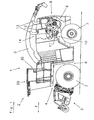
- Fig. 1 a side view of a forage harvester as an example of a self-propelled agricultural work machine according to the invention with partially uncovered drive unit from the left
- Fig. 2 an enlarged detail view of the exposed drive unit with ancillaries after Fig. 1
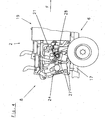
- Fig. 3 a view of the exposed drive unit of the forage harvester according to the invention of the embodiment from behind
- Fig. 4 one of the Fig. 2 corresponding detail view of the drive unit from the right
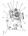
- Fig. 5 a perspective view of the partially schematically illustrated drive unit of the forage harvester Fig. 1 ,
- Fig. 1 shown in the present embodiment is a generally known forage harvester 2.
- the designed according to the features of the invention forage harvester 2 is in the embodiment shown with a trained as an attachment receiving and feeding device 3 for preferably in swaths on the ground equipped crop.
- the recorded crop is then fed to a work unit 4, not shown, of the working machine 1 for comminution and then transferred by means of the discharge chute 5 preferably to a transport vehicle.
- a chassis frame 6 work machine 1 which is propelled against the ground via wheels 7 self-propelled, is driven in total by a drive unit 8.
- Both the hydraulic traction drive in this case and the drives for the receiving and feeding device 3 and for the working unit 4 are based on this drive unit 8.
- Fig. 1 the partially only schematically illustrated drive unit 8 as a special feature of the invention recognizable.
- left side of the machine are particularly the rotary motion transmitting unit 9 and the outgoing from this main drive train 10, which mainly drives the power unit 4 by means of a drive belt 11 as a power transmission, visible. Furthermore, two exhaust silencers 12 with their tailpipes 13 can be recognized as an external identification mark for the two drive motors 14 of the drive unit 8.
- this compact and heavy drive unit 8 acts as a weight-balancing mass to heavy harvesting attachments in the front attachment.
- Fig. 1 the low design made possible by the use of two small drive motors 14 and the deep installation position of the drive unit 8 are clearly recognizable. This benefits advantageously a low center of gravity and thus the stability and driving stability.
- Fig. 2 shows in detail the rear of the forage harvester without panels in the same view as Fig. 1 ,
- the trained in this embodiment as a spur gear 15 rotational movement transmitting unit 9 of the drive unit 8 is connected by means of a support bracket 16 with the left side frame support 17 of the chassis frame 6.
- the connection in total rigidly shown in the drawing between the drive unit 8 and the chassis frame 6 is in a further embodiment, also elastically by, for example, rubber-metal fasteners conceivable.
- the main drive train 10 are in the Fig. 2 also the directly on the spur gear 15 flanged hydraulic pumps 18 of the other drives of the forage harvester as well as the cooling unit 19 and the air filter 20 visible.
- the main drive train 10 is driven by a direct drive through the spur gear 15 from the main motor 21 of the two drive motors 14 and is connected by a clutch 22 and switched off.
- the main motor 21 is also in constant engagement with the spur gear 15 and thus also with the directly on the spur gear 15 flanged hydraulic pumps 18th
- the auxiliary motor 24 is also in engagement with the spur gear 15, the drive unit 8 and thus rigidly coupled connection to the main motor 21, whereby the total power of both motors 21,24 for all outgoing from the spur gear 15 drives 10,18 available stands. Since the two drive motors 21,24 are identical in construction in the embodiment, it is thus possible to drive the forage harvester 2 according to the invention either by the main motor 21 with halved drive power, or operate with additionally switched off auxiliary motor 24 with the full overall drive power of the drive unit 8.
- the cooling unit 19 of the work machine 1 comprises centrally all the condensers for water, oil, charge air and coolant of the drive motors 14, the hydraulic systems, as well as the air conditioning of the cab 26th
- auxiliary frame 27 connects the motors 21, 24 approximately at the head end, and on the other hand forms the second connecting element of the drive unit 8 with the chassis frame 6 of the forage harvester 2 after the support frame 16.
- a pre-assembly drive unit 8 for a work machine 1 is provided according to the invention available due to Their compactness can be very advantageously installed transversely and so practically establishes a connection between the frame side members 17.
- the very good accessibility of the modules and the already mentioned favorable center of gravity position of the drive unit can only be achieved by this advantageous construction.
- Fig. 4 shows the rear of the forage harvester 2 accordingly Fig. 2 from the opposite right side of the machine.
- head on the motors 21, 24 of the subframe 27 is well recognized as a connecting and supporting element of the drive unit 8.
- the auxiliary drive 28 for the auxiliary cooling fan and generator which are not shown here, only from the front in the direction of travel F main motor 21 goes off.
- all units can be selectively driven by each motor, so that there is no main engine.
- the embodiment described is very advantageous, in particular from the point of view of costs, since this saves further units, drive elements and complex control systems.
- Fig. 5 shows in a perspective, partially schematic representation of the drive unit 8 of the forage harvester 2 according to the invention with the assemblies main motor 21, auxiliary motor 24, spur gear 15, support bracket 16, subframe 27 and clutches 22, 25. At the drives 29 of the spur gear 15 are in this Representation of the hydraulic pumps 18 not mounted.
- the Fig. 5 again makes it particularly clear how was created by the features of the invention, inter alia, a pre-assembly compact drive unit 8 for a self-propelled agricultural machine 1, which is shown in this embodiment with reference to a forage harvester 2.
- main motor 21 that this drives the switchable through the clutch 22 main drive train 10 in the direct power flow without detour via the rotary motion transmitting unit 9, while the possibility exists, the main drive train 10, the drive power of at least one other Engage motor 23.
- the coupling of the two motors 21 and 24 in the embodiment is done by the clutch 25.
- the clutch 25 provides the frictional connection between the auxiliary motor 24 and the spur gear 15 and thus also between the motors 21 and 24 ago. In order to keep the load for the coupling 25 as well as for the components of the spur gear 15 as low as possible at the moment of coupling, conditions for the synchronization of the motors 21,24 are necessary for the coupling process.
- the operator of the forage harvester 2 only detects with drive by the main motor 21 that the drive power is insufficient or is already established before the start of the work that both motors 21, 24 should be used, then first the Main motor 21 and then the auxiliary motor 24 are started.
- the auxiliary motor 24 is started in the usual way by its electric starter, not shown.
- the main motor 21 preferably tows the auxiliary motor 24 at low rotational speed upon actuation of the clutch 25, or stores kinetic energy which can be displaced by the main motor 21 in rotation and this from the instantaneous rotational speed of the main engine 21 can be used independently for the start of the auxiliary motor 24.
- the operator gives the start signal for the multi-motor drive to the control unit 30 of the work machine 1, whereupon this controls the motors 21,24 so that they run as synchronously as possible with respect to the speed.
- the clutch 25 is switched and thus completed the coupling.
- the desired synchronous speed is at the upper idle speed, since this is already relatively identical and in this speed range due to the only small torques of the motors 21,24, the torque differences are also very low.
- other synchronization options and other synchronization speeds or completely different technical solutions, for example, with freewheels are conceivable.
- the low component load, the operational safety and the costs speak in favor of the advantageous solution of the embodiment.
- the control and regulating device 30 of the working machine according to the invention also has monitoring and security functions. It is set up in such a way that the smallest disturbances of the drive unit 8 which are detected by sensors and which could represent a safety risk or lead to damage immediately lead at least to a controlled shutdown of the auxiliary engine 24 and / or to the switching of at least one of the clutches 22, 25.
Landscapes
- Life Sciences & Earth Sciences (AREA)
- Environmental Sciences (AREA)
- Combines (AREA)
- Harvester Elements (AREA)
- Agricultural Machines (AREA)
- Harvesting Machines For Root Crops (AREA)
- Harvesting Machines For Specific Crops (AREA)
- Control Of Position, Course, Altitude, Or Attitude Of Moving Bodies (AREA)
Claims (23)
- Récolteuse automotrice (1) notamment ramasseuse-hacheuse pour ramasser et hacher des produits de récolte tels que du maïs, des produits verts ou analogues, avec un châssis dont le bâti s'appuie sur le sol par des roues motrices (7), avec un entraînement de déplacement et au moins un entraînement pour au moins une unité entraînée de travail ou de récolte telle qu'une installation de ramassage et de transfert de produits (3), une unité de travail pour hacher, une goulotte d'éjection (5) pour transférer les produits, une puissance motrice totale variable étant fournie à tous les entraînements d'une unité d'entraînement (8) qui comporte au moins deux moteurs d'entraînement (14) et dont les au moins deux moteurs d'entraînement (14) sont associés à une unité de transmission (9) commune transmettant un mouvement de rotation, et avec une installation de commande et de régulation (30) par laquelle se commande la mise en service d'au moins un moteur d'entraînement supplémentaire (23),
dans laquelle, parmi au moins les deux moteurs d'entraînement (14), un moteur constitue le moteur principal (21) et une ligne de transmission principale (10) de la récolteuse est entraînée directement par le moteur principal (21), l'autre moteur d'entraînement (23) peut être branché en plus sélectivement et, après que l'utilisateur a donné un signal de démarrage pour le fonctionnement à plusieurs moteurs, l'installation de commande et de régulation (30) régule les moteurs (21, 23, 24) de telle sorte qu'ils tournent de la manière la plus synchrone possible quant à leur vitesse de rotation de sorte que, lorsqu'un synchronisme est atteint dans les limites d'une tolérance prédéterminée, un embrayage est enclenché et le couplage des moteurs (21, 23, 24) est ainsi réalisé. - Récolteuse automotrice selon la revendication 1,
caractérisée en ce que l'unité d'entraînement (8) constitue un ensemble compact, susceptible d'être pré-assemblé. - Récolteuse automotrice selon la revendication 2,
caractérisée en ce qu'un cadre auxiliaire (27) relie rigidement les moteurs d'entraînement (14), du côté de la tête, à l'opposé de la liaison avec l'unité (9) transmettant le mouvement de rotation. - Récolteuse automotrice selon l'une des revendications 1 à 3,
caractérisée en ce que l'unité d'entraînement (8) constitue un élément de liaison de la poutre latérale (17) du châssis de roulement (6) de la machine agricole automotrice (1). - Récolteuse automotrice selon les revendications 3 et 4,
caractérisée en ce que l'unité d'entraînement (8) constitue un élément de liaison des poutres latérales (17) du châssis de roulement (6) de la récolteuse automotrice (1), et d'une part le châssis auxiliaire (27) est relié et fixé de manière amovible à une poutre latérale de châssis (17) et d'autre part un bloc d'appui (16) de l'unité (9) transmettant le mouvement de rotation est relié et fixé de manière amovible à une autre poutre latérale de châssis (17) de manière à amortir les vibrations. - Récolteuse automotrice selon l'une des revendications 1 à 5,
caractérisée en ce que chaque moteur d'entraînement (14) comporte séparément les installations d'alimentation et d'évacuation nécessaires à son fonctionnement, un réservoir de carburant et un filtre à air étant communs. - Récolteuse automotrice selon l'une des revendications précédentes,
caractérisée en ce que les moteurs d'entraînement (14) de l'unité d'entraînement (8) ont un système de refroidissement commun. - Récolteuse automotrice selon l'une des revendications précédentes,
caractérisée en ce que le système de refroidissement commun des moteurs d'entraînement (14) de l'unité d'entraînement (8) est réalisé pour que le seul fonctionnement du moteur principal (21) dégage de la chaleur permettant de préchauffer au moins un autre moteur d'entraînement (23). - Récolteuse automotrice selon l'une des revendications 1 à 8,
caractérisée en ce que l'unité (9) transmettant le mouvement de rotation est constituée par une transmission à pignons droits ou une transmission planétaire. - Récolteuse automotrice selon l'une des revendications 1 à 9,
caractérisée en ce que les moteurs d'entraînement (14) de l'unité d'entraînement (8) constituent du côté de la sortie, avec l'unité transmettant le mouvement de rotation, une unité séparable et reliant l'ensemble. - Récolteuse automotrice selon l'une des revendications 1 à 10,
caractérisée en ce que l'un des moteurs d'entraînement est en prise permanente avec l'unité (9) transmettant le mouvement de rotation. - Récolteuse automotrice selon l'une des revendications 1 à 11,
caractérisée en ce que tous les moyens d'entraînement de la récolteuse (1) peuvent être entraînés par l'un des moteurs (14). - Récolteuse automotrice selon l'une des revendications 1 à 12,
caractérisée en ce que la puissance motrice pour des installations de refroidissement et le fonctionnement en générateur ne sont assurés que par l'un des moteurs d'entraînement (21). - Récolteuse automotrice selon l'une des revendications 1 à 13,
caractérisée en ce que la ligne d'entraînement principale (10) peut être entraînée de façon commutable. - Récolteuse automotrice selon l'une des revendications 1 à 14,
caractérisée en ce que la ligne de transmission principale (10) est entraînée en commun par le moteur principal (21) et au moins un autre moteur (23). - Récolteuse automotrice selon l'une des revendications précédentes,
caractérisée en ce que d'autres entraînements de la récolteuse (1) sont issus de l'unité (9) transmettant le mouvement de rotation. - Récolteuse automotrice selon l'une des revendications précédentes,
caractérisée en ce que tous les entraînements partant de l'unité (9) transmettant le mouvement de rotation peuvent être entraînés en commun par tous les moteurs d'entraînement (14). - Récolteuse automotrice selon l'une des quelconques revendications,
caractérisée en ce que des installations de commande et de régulation (30) sont prévues pour réaliser un état d'équilibre pour le couple fourni et la vitesse de rotation entre les moteurs d'entraînement pouvant être accouplés (14) de l'unité d'entraînement (8). - Récolteuse automotrice selon l'une des revendications précédentes,
caractérisée en ce que des installations de commande et de régulation (30) sont prévues pour, après un signal de déclenchement, assurer automatiquement les conditions nécessaires à l'accouplement des moteurs d'entraînement (14) et effectuer cet accouplement. - Récolteuse automotrice selon l'une des revendications précédentes,
caractérisée en ce que des installations de commande et de régulation (30) sont prévues pour surveiller l'état de fonctionnement et la coopération des moteurs d'entraînement (14) de l'unité d'entraînement pour qu'en cas de perturbation, des mesures appropriées soient prises immédiatement pour éviter des accidents et les dommages. - Récolteuse automotrice selon la revendication 20,
caractérisée en ce que les installations de commande et de régulation (30) sont conçues pour surveiller l'état de fonctionnement et la coopération des moteurs d'entraînement (14) pour qu'en cas de perturbation, au moins immédiatement le flux de force de l'au moins un autre moteur (23) soit coupé, par un embrayage (25), de l'unité (9) qui transmet le mouvement de rotation. - Récolteuse automotrice selon l'une des revendications précédentes,
caractérisée en ce que la nature d'utilisation et/ou les conditions d'utilisation définissent le nombre de moteurs (14) utilisés pour l'entraînement dans l'unité d'entraînement (8). - Récolteuse automotrice selon les revendications 22,
caractérisée en ce que, pour le mode de fonctionnement correspondant à la circulation sur route, un seul moteur (14) de l'unité d'entraînement (8) entraîne la récolteuse (1).
Applications Claiming Priority (1)
| Application Number | Priority Date | Filing Date | Title |
|---|---|---|---|
| DE102004046467A DE102004046467B4 (de) | 2004-09-24 | 2004-09-24 | Selbstfahrende Erntemaschine |
Publications (3)
| Publication Number | Publication Date |
|---|---|
| EP1640201A1 EP1640201A1 (fr) | 2006-03-29 |
| EP1640201B1 EP1640201B1 (fr) | 2008-04-30 |
| EP1640201B2 true EP1640201B2 (fr) | 2015-09-02 |
Family
ID=35432311
Family Applications (1)
| Application Number | Title | Priority Date | Filing Date |
|---|---|---|---|
| EP05020755.4A Expired - Lifetime EP1640201B2 (fr) | 2004-09-24 | 2005-09-23 | Moissonneuse automotrice |
Country Status (5)
| Country | Link |
|---|---|
| US (1) | US20060086076A1 (fr) |
| EP (1) | EP1640201B2 (fr) |
| AT (1) | ATE393717T1 (fr) |
| DE (2) | DE102004046467B4 (fr) |
| EA (1) | EA008197B1 (fr) |
Families Citing this family (25)
| Publication number | Priority date | Publication date | Assignee | Title |
|---|---|---|---|---|
| DE102006004143A1 (de) * | 2006-01-27 | 2007-08-02 | Claas Selbstfahrende Erntemaschinen Gmbh | Landwirtschaftlich nutzbares Motorfahrzeug |
| DE102007019202B4 (de) * | 2007-04-20 | 2015-05-21 | Wirtgen Gmbh | Selbstfahrende Baumaschine, inbesondere Straßenfräsmaschine, Recycler oder Stabilisierer |
| DE102007019661B4 (de) | 2007-04-26 | 2019-08-08 | Deere & Company | Selbstfahrende landwirtschaftliche Erntemaschine mit zwei Verbrennungsmotoren |
| DE102008009447B4 (de) | 2008-02-15 | 2015-11-19 | Deere & Company | Selbstfahrende landwirtschaftliche Erntemaschine mit zwei Verbrennungsmotoren |
| US8074433B2 (en) * | 2008-03-14 | 2011-12-13 | Deere & Company | Agricultural harvester with auxiliary power unit and intelligent power management |
| DE102009028055B4 (de) | 2008-08-04 | 2020-01-16 | Deere & Company | Selbstfahrende Erntemaschine |
| DE102009028094B4 (de) | 2008-08-04 | 2019-10-31 | Deere & Company | Selbstfahrende Erntemaschine |
| US8001771B2 (en) | 2008-08-08 | 2011-08-23 | Deere & Company | Dual engine work vehicle with control for exhaust aftertreatment regeneration |
| DE102009028056B4 (de) | 2008-08-12 | 2022-02-10 | Deere & Company | Selbstfahrende Erntemaschine |
| EP2774473B1 (fr) | 2009-05-08 | 2017-08-09 | Deere & Company | Moissonneuse automotrice |
| US8209095B2 (en) * | 2009-05-11 | 2012-06-26 | Deere & Company | Agricultural harvester with dual engines and power sharing based on engine temperature |
| US8150584B2 (en) * | 2009-05-12 | 2012-04-03 | Deere & Company | Generation and starting system |
| US8087900B2 (en) * | 2009-05-22 | 2012-01-03 | Deere & Company | Agricultural harvester with propulsion load shifting between dual engines |
| US7974757B2 (en) * | 2009-05-22 | 2011-07-05 | Deere & Company | Agricultural harvester with dual engine failure power transfer system |
| US8008800B2 (en) * | 2009-05-22 | 2011-08-30 | Deere & Company | Harvester multiple engine energy control system |
| US8897972B2 (en) * | 2009-05-22 | 2014-11-25 | Deere & Company | Harvester load control system |
| DE102009047343A1 (de) * | 2009-12-01 | 2011-06-09 | Deere & Company, Moline | Antriebsanordnung und Verfahren für eine Arbeitsmaschine mit zwei Verbrennungsmotoren |
| DE102011117860A1 (de) | 2011-11-08 | 2013-05-08 | Claas Selbstfahrende Erntemaschinen Gmbh | Verfahren und System zum Ernten und Silieren von Futtermaterial |
| US20140102432A1 (en) * | 2012-10-16 | 2014-04-17 | Diamond Products, Limited | Cooling System For Concrete Saw |
| DE102013206305B3 (de) * | 2013-04-10 | 2014-07-10 | Deere & Company | Selbstfahrende landwirtschaftliche Erntemaschine mit zwei Verbrennungsmotoren |
| JP6018033B2 (ja) * | 2013-10-23 | 2016-11-02 | ヤンマー株式会社 | コンバイン |
| US9668415B2 (en) | 2013-12-30 | 2017-06-06 | Cnh Industrial America Llc | Basecutter blade control for a cane harvester |
| DE102014001839A1 (de) * | 2014-02-11 | 2015-08-13 | Caterpillar Paving Products Inc. (Gesellschaft nach dem Recht des Staates Oklahoma, USA) | Pumpenantriebsvorrichtung für eine Arbeitsmaschine |
| CA3001527A1 (fr) * | 2015-10-22 | 2017-04-27 | Desch Antriebstechnik Gmbh & Co. Kg | Dispositif d'entrainement destine a une machine de construction |
| US10383278B2 (en) * | 2016-07-06 | 2019-08-20 | Tribine Industries Llc | Airflow for an agricultural harvesting combine |
Citations (1)
| Publication number | Priority date | Publication date | Assignee | Title |
|---|---|---|---|---|
| DE3644767A1 (de) † | 1986-12-30 | 1988-07-14 | Friedrich Fischer | Verfahren und vorrichtung zum ausbringen von saatgut oder dergleichen materialien |
Family Cites Families (24)
| Publication number | Priority date | Publication date | Assignee | Title |
|---|---|---|---|---|
| GB546237A (en) * | 1940-11-25 | 1942-07-03 | Gear Grinding Mach Co | Multimotored vehicle driving unit |
| US2366646A (en) * | 1943-01-18 | 1945-01-02 | Borg Warner | Multiengine drive |
| US2689621A (en) * | 1947-09-13 | 1954-09-21 | Four Wheel Drive Auto Company | Truck with interrelated multiple prime movers, power take-off couplings, and operating controls therefor |
| US2595336A (en) * | 1948-02-09 | 1952-05-06 | Corsentino Pete | Power transmission mechanism for farm implements |
| DE915779C (de) * | 1952-12-17 | 1954-07-29 | Carl F W Borgward G M B H | Kraftfahrzeug mit zwei oder mehreren Antriebsmaschinen |
| US2877664A (en) * | 1957-03-28 | 1959-03-17 | Sperry Rand Corp | Forage harvester drive means |
| SE320274B (fr) * | 1962-10-02 | 1970-02-02 | R Muotka | |
| DE1780052A1 (de) * | 1968-07-27 | 1972-01-13 | Kloeckner Humboldt Deutz Ag | Landwirtschaftlich nutzbares Motorfahrzeug mit zwei Antriebseinheiten |
| US3736732A (en) * | 1971-10-12 | 1973-06-05 | Deere & Co | Auxiliary drive system for combines |
| SU507464A1 (ru) * | 1974-06-24 | 1976-03-25 | Предприятие П/Я А-7656 | Гидромеханический привод самоходной машины |
| US4161991A (en) * | 1975-05-12 | 1979-07-24 | Lely Nv C Van Der | Tractors |
| NL7505526A (nl) * | 1975-05-12 | 1976-11-16 | Lely Nv C Van Der | Trekker. |
| DE3439710A1 (de) * | 1984-10-30 | 1986-05-07 | Baldur 6431 Hohenroda Wildner | Mehrzweckgeraetetraeger |
| NL8500760A (nl) * | 1985-03-15 | 1986-10-01 | Texas Industries Inc | Trekker, in het bijzonder een landbouwtrekker. |
| DD262061A1 (de) * | 1987-07-07 | 1988-11-16 | Landtechnik K | Rotationskolbenverbrennungskraftmaschine mit mehrkammersystem und arbeitsprinzip dazu |
| US5242146A (en) * | 1988-11-14 | 1993-09-07 | Navistar International Transportation Corp. | Engine mount having improved vibration isolation |
| DE4123681A1 (de) * | 1991-07-17 | 1993-01-21 | Aatec Assembling Automations T | Einrichtung zum ueberlastschutz und abbremsen eines durch einen motor angetriebenen maschinenteils |
| DE4210258A1 (de) * | 1992-03-28 | 1993-09-30 | Man Nutzfahrzeuge Ag | Kraftfahrzeug, insbesondere Lastkraftwagen oder Omnibus, mit zwei Motoren |
| US5627438A (en) * | 1995-01-25 | 1997-05-06 | Barrett; Robert D. | Pulsing control for an inertial drive system for a multi-motor binary array vehicle |
| DE19517262A1 (de) * | 1995-05-11 | 1996-11-14 | Ziegler Albert Gmbh Co Kg | Kraftfahrzeug mit einem Nebenverbraucher, insbesondere Feuerwehrfahrzeug mit einer Löschpumpe |
| US6247295B1 (en) * | 1999-10-28 | 2001-06-19 | New Holland North America, Inc. | Hydro-mechanical transmission system for an agricultural combine |
| DE20007994U1 (de) * | 2000-05-04 | 2001-09-13 | Maschinenfabrik Bernard Krone GmbH, 48480 Spelle | Selbstfahrende Erntemaschine, insbesondere Feldhäcksler |
| US6717281B1 (en) * | 2000-10-26 | 2004-04-06 | Dennis Brandon | Electric generator and motor drive system |
| US6666007B2 (en) * | 2001-12-12 | 2003-12-23 | Case Corporation | Hydro-mechanical variable speed feeder/header drive for an agricultural combine |
-
2004
- 2004-09-24 DE DE102004046467A patent/DE102004046467B4/de not_active Withdrawn - After Issue
-
2005
- 2005-09-23 DE DE502005003896T patent/DE502005003896D1/de not_active Expired - Lifetime
- 2005-09-23 EA EA200501340A patent/EA008197B1/ru unknown
- 2005-09-23 US US11/162,806 patent/US20060086076A1/en not_active Abandoned
- 2005-09-23 AT AT05020755T patent/ATE393717T1/de not_active IP Right Cessation
- 2005-09-23 EP EP05020755.4A patent/EP1640201B2/fr not_active Expired - Lifetime
Patent Citations (1)
| Publication number | Priority date | Publication date | Assignee | Title |
|---|---|---|---|---|
| DE3644767A1 (de) † | 1986-12-30 | 1988-07-14 | Friedrich Fischer | Verfahren und vorrichtung zum ausbringen von saatgut oder dergleichen materialien |
Non-Patent Citations (4)
| Title |
|---|
| "AUSZUG AUS RAUCH PREISLISTE", May 1995 † |
| "AUSZUG AUS RAUCH PREISLISTE", November 1993 † |
| "RAUCH KOMET50BEDIENUNGSANLEITUNG", 1991 † |
| "RAUCH ZEICHNUNG FREILAUF", 13 January 1993 † |
Also Published As
| Publication number | Publication date |
|---|---|
| DE102004046467A1 (de) | 2006-04-13 |
| EA008197B1 (ru) | 2007-04-27 |
| EP1640201B1 (fr) | 2008-04-30 |
| EP1640201A1 (fr) | 2006-03-29 |
| EA200501340A1 (ru) | 2006-04-28 |
| DE102004046467B4 (de) | 2006-08-31 |
| US20060086076A1 (en) | 2006-04-27 |
| ATE393717T1 (de) | 2008-05-15 |
| DE502005003896D1 (de) | 2008-06-12 |
Similar Documents
| Publication | Publication Date | Title |
|---|---|---|
| EP1640201B2 (fr) | Moissonneuse automotrice | |
| DE102007037631A1 (de) | Starterwechselstromerzeuger-Zubehörantriebssystem für ein Hybridfahrzeug | |
| EP2952087B1 (fr) | Système d'entraînement d'une moissonneuse automotrice | |
| EP3259975B1 (fr) | Engin agricole et procédé de fonctionnement d'un engin agricole | |
| DE102009003242B4 (de) | Antriebssystem für eine Erntemaschine | |
| EP3906770B1 (fr) | Système d'entraînement pour un engin d'abattage-façonnage autonome | |
| EP2329981A1 (fr) | Agencement d'entraînement et procédé pour une machine de travail dotée de deux moteurs à combustion | |
| EP1570724B1 (fr) | Disposition d'actionnement pour actionner la tête de récolte d'une machine de récolte | |
| EP2857246B1 (fr) | Machine agricole | |
| DE102014009159B4 (de) | Schneidwerk mit Eingangsgetriebe | |
| DE102009028094B4 (de) | Selbstfahrende Erntemaschine | |
| DE102007022077A1 (de) | Geriebeanordnung mit verstellbarem Übersetzungsverhältnis | |
| DE102009028056B4 (de) | Selbstfahrende Erntemaschine | |
| EP2269439B1 (fr) | Moissonneuse agricole automobile dotée de deux moteurs à combustion | |
| DE102007019661B4 (de) | Selbstfahrende landwirtschaftliche Erntemaschine mit zwei Verbrennungsmotoren | |
| EP2132975B1 (fr) | Système d'entraînement pour une moissonneuse | |
| EP1813459B2 (fr) | Véhicule à moteur utilitaire agricole | |
| DE202011002195U1 (de) | Selbstfahrende landwirtschaftliche Erntemaschine mit einem elektromotorisch angetriebenen Arbeitsorgan | |
| DE102008009447A1 (de) | Selbstfahrende landwirtschaftliche Erntemaschine mit zwei Verbrennungsmotoren | |
| EP2359676A1 (fr) | Machine de travail agricole | |
| EP1632131A1 (fr) | Système d'entraînement d'un dispositif d'alimentation pour une machine agricole | |
| EP2789825B1 (fr) | Moissonneuse | |
| DE102009028055B4 (de) | Selbstfahrende Erntemaschine | |
| DE102013206305B3 (de) | Selbstfahrende landwirtschaftliche Erntemaschine mit zwei Verbrennungsmotoren | |
| EP3906769A1 (fr) | Système d'entraînement pour un engin d'abattage-façonnage autonome |
Legal Events
| Date | Code | Title | Description |
|---|---|---|---|
| PUAI | Public reference made under article 153(3) epc to a published international application that has entered the european phase |
Free format text: ORIGINAL CODE: 0009012 |
|
| AK | Designated contracting states |
Kind code of ref document: A1 Designated state(s): AT BE BG CH CY CZ DE DK EE ES FI FR GB GR HU IE IS IT LI LT LU LV MC NL PL PT RO SE SI SK TR |
|
| AX | Request for extension of the european patent |
Extension state: AL BA HR MK YU |
|
| 17P | Request for examination filed |
Effective date: 20060928 |
|
| 17Q | First examination report despatched |
Effective date: 20061030 |
|
| AKX | Designation fees paid |
Designated state(s): AT BE BG CH CY CZ DE DK EE ES FI FR GB GR HU IE IS IT LI LT LU LV MC NL PL PT RO SE SI SK TR |
|
| GRAP | Despatch of communication of intention to grant a patent |
Free format text: ORIGINAL CODE: EPIDOSNIGR1 |
|
| GRAS | Grant fee paid |
Free format text: ORIGINAL CODE: EPIDOSNIGR3 |
|
| GRAA | (expected) grant |
Free format text: ORIGINAL CODE: 0009210 |
|
| AK | Designated contracting states |
Kind code of ref document: B1 Designated state(s): AT BE BG CH CY CZ DE DK EE ES FI FR GB GR HU IE IS IT LI LT LU LV MC NL PL PT RO SE SI SK TR |
|
| REG | Reference to a national code |
Ref country code: GB Ref legal event code: FG4D Free format text: NOT ENGLISH |
|
| REG | Reference to a national code |
Ref country code: CH Ref legal event code: EP |
|
| REG | Reference to a national code |
Ref country code: IE Ref legal event code: FG4D Free format text: LANGUAGE OF EP DOCUMENT: GERMAN |
|
| REF | Corresponds to: |
Ref document number: 502005003896 Country of ref document: DE Date of ref document: 20080612 Kind code of ref document: P |
|
| PG25 | Lapsed in a contracting state [announced via postgrant information from national office to epo] |
Ref country code: SI Free format text: LAPSE BECAUSE OF FAILURE TO SUBMIT A TRANSLATION OF THE DESCRIPTION OR TO PAY THE FEE WITHIN THE PRESCRIBED TIME-LIMIT Effective date: 20080430 |
|
| PG25 | Lapsed in a contracting state [announced via postgrant information from national office to epo] |
Ref country code: PT Free format text: LAPSE BECAUSE OF FAILURE TO SUBMIT A TRANSLATION OF THE DESCRIPTION OR TO PAY THE FEE WITHIN THE PRESCRIBED TIME-LIMIT Effective date: 20080930 Ref country code: FI Free format text: LAPSE BECAUSE OF FAILURE TO SUBMIT A TRANSLATION OF THE DESCRIPTION OR TO PAY THE FEE WITHIN THE PRESCRIBED TIME-LIMIT Effective date: 20080430 Ref country code: ES Free format text: LAPSE BECAUSE OF FAILURE TO SUBMIT A TRANSLATION OF THE DESCRIPTION OR TO PAY THE FEE WITHIN THE PRESCRIBED TIME-LIMIT Effective date: 20080810 Ref country code: BG Free format text: LAPSE BECAUSE OF FAILURE TO SUBMIT A TRANSLATION OF THE DESCRIPTION OR TO PAY THE FEE WITHIN THE PRESCRIBED TIME-LIMIT Effective date: 20080730 |
|
| PG25 | Lapsed in a contracting state [announced via postgrant information from national office to epo] |
Ref country code: PL Free format text: LAPSE BECAUSE OF FAILURE TO SUBMIT A TRANSLATION OF THE DESCRIPTION OR TO PAY THE FEE WITHIN THE PRESCRIBED TIME-LIMIT Effective date: 20080430 Ref country code: LV Free format text: LAPSE BECAUSE OF FAILURE TO SUBMIT A TRANSLATION OF THE DESCRIPTION OR TO PAY THE FEE WITHIN THE PRESCRIBED TIME-LIMIT Effective date: 20080430 |
|
| REG | Reference to a national code |
Ref country code: IE Ref legal event code: FD4D |
|
| PG25 | Lapsed in a contracting state [announced via postgrant information from national office to epo] |
Ref country code: IS Free format text: LAPSE BECAUSE OF FAILURE TO SUBMIT A TRANSLATION OF THE DESCRIPTION OR TO PAY THE FEE WITHIN THE PRESCRIBED TIME-LIMIT Effective date: 20080830 |
|
| PG25 | Lapsed in a contracting state [announced via postgrant information from national office to epo] |
Ref country code: SE Free format text: LAPSE BECAUSE OF FAILURE TO SUBMIT A TRANSLATION OF THE DESCRIPTION OR TO PAY THE FEE WITHIN THE PRESCRIBED TIME-LIMIT Effective date: 20080731 Ref country code: LT Free format text: LAPSE BECAUSE OF FAILURE TO SUBMIT A TRANSLATION OF THE DESCRIPTION OR TO PAY THE FEE WITHIN THE PRESCRIBED TIME-LIMIT Effective date: 20080430 Ref country code: IE Free format text: LAPSE BECAUSE OF FAILURE TO SUBMIT A TRANSLATION OF THE DESCRIPTION OR TO PAY THE FEE WITHIN THE PRESCRIBED TIME-LIMIT Effective date: 20080430 Ref country code: DK Free format text: LAPSE BECAUSE OF FAILURE TO SUBMIT A TRANSLATION OF THE DESCRIPTION OR TO PAY THE FEE WITHIN THE PRESCRIBED TIME-LIMIT Effective date: 20080430 Ref country code: CZ Free format text: LAPSE BECAUSE OF FAILURE TO SUBMIT A TRANSLATION OF THE DESCRIPTION OR TO PAY THE FEE WITHIN THE PRESCRIBED TIME-LIMIT Effective date: 20080430 |
|
| PLBI | Opposition filed |
Free format text: ORIGINAL CODE: 0009260 |
|
| EN | Fr: translation not filed | ||
| PG25 | Lapsed in a contracting state [announced via postgrant information from national office to epo] |
Ref country code: SK Free format text: LAPSE BECAUSE OF FAILURE TO SUBMIT A TRANSLATION OF THE DESCRIPTION OR TO PAY THE FEE WITHIN THE PRESCRIBED TIME-LIMIT Effective date: 20080430 Ref country code: RO Free format text: LAPSE BECAUSE OF FAILURE TO SUBMIT A TRANSLATION OF THE DESCRIPTION OR TO PAY THE FEE WITHIN THE PRESCRIBED TIME-LIMIT Effective date: 20080430 |
|
| 26 | Opposition filed |
Opponent name: CLAAS KGAA MBH Effective date: 20090129 |
|
| PLAX | Notice of opposition and request to file observation + time limit sent |
Free format text: ORIGINAL CODE: EPIDOSNOBS2 |
|
| PG25 | Lapsed in a contracting state [announced via postgrant information from national office to epo] |
Ref country code: MC Free format text: LAPSE BECAUSE OF NON-PAYMENT OF DUE FEES Effective date: 20080930 Ref country code: FR Free format text: LAPSE BECAUSE OF FAILURE TO SUBMIT A TRANSLATION OF THE DESCRIPTION OR TO PAY THE FEE WITHIN THE PRESCRIBED TIME-LIMIT Effective date: 20090227 Ref country code: EE Free format text: LAPSE BECAUSE OF FAILURE TO SUBMIT A TRANSLATION OF THE DESCRIPTION OR TO PAY THE FEE WITHIN THE PRESCRIBED TIME-LIMIT Effective date: 20080430 |
|
| NLR1 | Nl: opposition has been filed with the epo |
Opponent name: CLAAS KGAA MBH |
|
| PLAF | Information modified related to communication of a notice of opposition and request to file observations + time limit |
Free format text: ORIGINAL CODE: EPIDOSCOBS2 |
|
| PG25 | Lapsed in a contracting state [announced via postgrant information from national office to epo] |
Ref country code: IT Free format text: LAPSE BECAUSE OF FAILURE TO SUBMIT A TRANSLATION OF THE DESCRIPTION OR TO PAY THE FEE WITHIN THE PRESCRIBED TIME-LIMIT Effective date: 20080430 |
|
| PLBB | Reply of patent proprietor to notice(s) of opposition received |
Free format text: ORIGINAL CODE: EPIDOSNOBS3 |
|
| PG25 | Lapsed in a contracting state [announced via postgrant information from national office to epo] |
Ref country code: AT Free format text: LAPSE BECAUSE OF NON-PAYMENT OF DUE FEES Effective date: 20080923 |
|
| REG | Reference to a national code |
Ref country code: CH Ref legal event code: PL |
|
| GBPC | Gb: european patent ceased through non-payment of renewal fee |
Effective date: 20090923 |
|
| PG25 | Lapsed in a contracting state [announced via postgrant information from national office to epo] |
Ref country code: LU Free format text: LAPSE BECAUSE OF NON-PAYMENT OF DUE FEES Effective date: 20080923 Ref country code: HU Free format text: LAPSE BECAUSE OF FAILURE TO SUBMIT A TRANSLATION OF THE DESCRIPTION OR TO PAY THE FEE WITHIN THE PRESCRIBED TIME-LIMIT Effective date: 20081101 Ref country code: CY Free format text: LAPSE BECAUSE OF FAILURE TO SUBMIT A TRANSLATION OF THE DESCRIPTION OR TO PAY THE FEE WITHIN THE PRESCRIBED TIME-LIMIT Effective date: 20080430 |
|
| PG25 | Lapsed in a contracting state [announced via postgrant information from national office to epo] |
Ref country code: TR Free format text: LAPSE BECAUSE OF FAILURE TO SUBMIT A TRANSLATION OF THE DESCRIPTION OR TO PAY THE FEE WITHIN THE PRESCRIBED TIME-LIMIT Effective date: 20080430 |
|
| PG25 | Lapsed in a contracting state [announced via postgrant information from national office to epo] |
Ref country code: LI Free format text: LAPSE BECAUSE OF NON-PAYMENT OF DUE FEES Effective date: 20090930 Ref country code: GR Free format text: LAPSE BECAUSE OF FAILURE TO SUBMIT A TRANSLATION OF THE DESCRIPTION OR TO PAY THE FEE WITHIN THE PRESCRIBED TIME-LIMIT Effective date: 20080731 Ref country code: CH Free format text: LAPSE BECAUSE OF NON-PAYMENT OF DUE FEES Effective date: 20090930 |
|
| PLCK | Communication despatched that opposition was rejected |
Free format text: ORIGINAL CODE: EPIDOSNREJ1 |
|
| PG25 | Lapsed in a contracting state [announced via postgrant information from national office to epo] |
Ref country code: GB Free format text: LAPSE BECAUSE OF NON-PAYMENT OF DUE FEES Effective date: 20090923 |
|
| APBM | Appeal reference recorded |
Free format text: ORIGINAL CODE: EPIDOSNREFNO |
|
| APBP | Date of receipt of notice of appeal recorded |
Free format text: ORIGINAL CODE: EPIDOSNNOA2O |
|
| APAH | Appeal reference modified |
Free format text: ORIGINAL CODE: EPIDOSCREFNO |
|
| APBQ | Date of receipt of statement of grounds of appeal recorded |
Free format text: ORIGINAL CODE: EPIDOSNNOA3O |
|
| APBU | Appeal procedure closed |
Free format text: ORIGINAL CODE: EPIDOSNNOA9O |
|
| PUAH | Patent maintained in amended form |
Free format text: ORIGINAL CODE: 0009272 |
|
| STAA | Information on the status of an ep patent application or granted ep patent |
Free format text: STATUS: PATENT MAINTAINED AS AMENDED |
|
| 27A | Patent maintained in amended form |
Effective date: 20150902 |
|
| AK | Designated contracting states |
Kind code of ref document: B2 Designated state(s): AT BE BG CH CY CZ DE DK EE ES FI FR GB GR HU IE IS IT LI LT LU LV MC NL PL PT RO SE SI SK TR |
|
| REG | Reference to a national code |
Ref country code: DE Ref legal event code: R102 Ref document number: 502005003896 Country of ref document: DE |
|
| REG | Reference to a national code |
Ref country code: NL Ref legal event code: FP |
|
| REG | Reference to a national code |
Ref country code: BE Ref legal event code: HC Owner name: MASCHINENFABRIK BERNARD KRONE GMBH & CO. KG; DE Free format text: DETAILS ASSIGNMENT: CHANGE OF OWNER(S), CHANGE OF OWNER(S) NAME Effective date: 20210209 |
|
| REG | Reference to a national code |
Ref country code: DE Ref legal event code: R081 Ref document number: 502005003896 Country of ref document: DE Owner name: KRONE AGRICULTURE SE, DE Free format text: FORMER OWNER: MASCHINENFABRIK BERNARD KRONE GMBH, 48480 SPELLE, DE |
|
| REG | Reference to a national code |
Ref country code: NL Ref legal event code: PD Owner name: KRONE AGRICULTURE SE; DE Free format text: DETAILS ASSIGNMENT: CHANGE OF OWNER(S), MERGE; FORMER OWNER NAME: MASCHINENFABRIK KRONE BETEILIGUNGS-GMBH Effective date: 20211126 Ref country code: NL Ref legal event code: HC Owner name: MASCHINENFABRIK KRONE BETEILIGUNGS-GMBH; DE Free format text: DETAILS ASSIGNMENT: CHANGE OF OWNER(S), CHANGE OF OWNER(S) NAME; FORMER OWNER NAME: MASCHINENFABRIK BERNARD KRONE GMBH Effective date: 20211126 |
|
| REG | Reference to a national code |
Ref country code: DE Ref legal event code: R084 Ref document number: 502005003896 Country of ref document: DE |
|
| PGFP | Annual fee paid to national office [announced via postgrant information from national office to epo] |
Ref country code: NL Payment date: 20220922 Year of fee payment: 18 Ref country code: DE Payment date: 20220920 Year of fee payment: 18 |
|
| PGFP | Annual fee paid to national office [announced via postgrant information from national office to epo] |
Ref country code: BE Payment date: 20220921 Year of fee payment: 18 |
|
| P01 | Opt-out of the competence of the unified patent court (upc) registered |
Effective date: 20230517 |
|
| REG | Reference to a national code |
Ref country code: DE Ref legal event code: R119 Ref document number: 502005003896 Country of ref document: DE |
|
| REG | Reference to a national code |
Ref country code: NL Ref legal event code: MM Effective date: 20231001 |
|
| REG | Reference to a national code |
Ref country code: BE Ref legal event code: MM Effective date: 20230930 |
|
| PG25 | Lapsed in a contracting state [announced via postgrant information from national office to epo] |
Ref country code: NL Free format text: LAPSE BECAUSE OF NON-PAYMENT OF DUE FEES Effective date: 20231001 |
|
| PG25 | Lapsed in a contracting state [announced via postgrant information from national office to epo] |
Ref country code: NL Free format text: LAPSE BECAUSE OF NON-PAYMENT OF DUE FEES Effective date: 20231001 |
|
| PG25 | Lapsed in a contracting state [announced via postgrant information from national office to epo] |
Ref country code: DE Free format text: LAPSE BECAUSE OF NON-PAYMENT OF DUE FEES Effective date: 20240403 |
|
| PG25 | Lapsed in a contracting state [announced via postgrant information from national office to epo] |
Ref country code: BE Free format text: LAPSE BECAUSE OF NON-PAYMENT OF DUE FEES Effective date: 20230930 |