EP1637726A1 - Anordnung eines Luftfiltergehäuses für eine Brennkraftmaschine im Motorraum eines Kraftfahrzeugs - Google Patents
Anordnung eines Luftfiltergehäuses für eine Brennkraftmaschine im Motorraum eines Kraftfahrzeugs Download PDFInfo
- Publication number
- EP1637726A1 EP1637726A1 EP05017571A EP05017571A EP1637726A1 EP 1637726 A1 EP1637726 A1 EP 1637726A1 EP 05017571 A EP05017571 A EP 05017571A EP 05017571 A EP05017571 A EP 05017571A EP 1637726 A1 EP1637726 A1 EP 1637726A1
- Authority
- EP
- European Patent Office
- Prior art keywords
- air
- internal combustion
- combustion engine
- rohluftschale
- filter housing
- Prior art date
- Legal status (The legal status is an assumption and is not a legal conclusion. Google has not performed a legal analysis and makes no representation as to the accuracy of the status listed.)
- Granted
Links
Images
Classifications
-
- F—MECHANICAL ENGINEERING; LIGHTING; HEATING; WEAPONS; BLASTING
- F02—COMBUSTION ENGINES; HOT-GAS OR COMBUSTION-PRODUCT ENGINE PLANTS
- F02M—SUPPLYING COMBUSTION ENGINES IN GENERAL WITH COMBUSTIBLE MIXTURES OR CONSTITUENTS THEREOF
- F02M35/00—Combustion-air cleaners, air intakes, intake silencers, or induction systems specially adapted for, or arranged on, internal-combustion engines
- F02M35/10—Air intakes; Induction systems
- F02M35/10006—Air intakes; Induction systems characterised by the position of elements of the air intake system in direction of the air intake flow, i.e. between ambient air inlet and supply to the combustion chamber
- F02M35/10013—Means upstream of the air filter; Connection to the ambient air
-
- F—MECHANICAL ENGINEERING; LIGHTING; HEATING; WEAPONS; BLASTING
- F02—COMBUSTION ENGINES; HOT-GAS OR COMBUSTION-PRODUCT ENGINE PLANTS
- F02M—SUPPLYING COMBUSTION ENGINES IN GENERAL WITH COMBUSTIBLE MIXTURES OR CONSTITUENTS THEREOF
- F02M35/00—Combustion-air cleaners, air intakes, intake silencers, or induction systems specially adapted for, or arranged on, internal-combustion engines
- F02M35/02—Air cleaners
- F02M35/0201—Housings; Casings; Frame constructions; Lids; Manufacturing or assembling thereof
- F02M35/021—Arrangements of air flow meters in or on air cleaner housings
-
- F—MECHANICAL ENGINEERING; LIGHTING; HEATING; WEAPONS; BLASTING
- F02—COMBUSTION ENGINES; HOT-GAS OR COMBUSTION-PRODUCT ENGINE PLANTS
- F02M—SUPPLYING COMBUSTION ENGINES IN GENERAL WITH COMBUSTIBLE MIXTURES OR CONSTITUENTS THEREOF
- F02M35/00—Combustion-air cleaners, air intakes, intake silencers, or induction systems specially adapted for, or arranged on, internal-combustion engines
- F02M35/10—Air intakes; Induction systems
- F02M35/10373—Sensors for intake systems
- F02M35/10386—Sensors for intake systems for flow rate
-
- F—MECHANICAL ENGINEERING; LIGHTING; HEATING; WEAPONS; BLASTING
- F02—COMBUSTION ENGINES; HOT-GAS OR COMBUSTION-PRODUCT ENGINE PLANTS
- F02M—SUPPLYING COMBUSTION ENGINES IN GENERAL WITH COMBUSTIBLE MIXTURES OR CONSTITUENTS THEREOF
- F02M35/00—Combustion-air cleaners, air intakes, intake silencers, or induction systems specially adapted for, or arranged on, internal-combustion engines
- F02M35/16—Combustion-air cleaners, air intakes, intake silencers, or induction systems specially adapted for, or arranged on, internal-combustion engines characterised by use in vehicles
- F02M35/161—Arrangement of the air intake system in the engine compartment, e.g. with respect to the bonnet or the vehicle front face
-
- F—MECHANICAL ENGINEERING; LIGHTING; HEATING; WEAPONS; BLASTING
- F02—COMBUSTION ENGINES; HOT-GAS OR COMBUSTION-PRODUCT ENGINE PLANTS
- F02M—SUPPLYING COMBUSTION ENGINES IN GENERAL WITH COMBUSTIBLE MIXTURES OR CONSTITUENTS THEREOF
- F02M35/00—Combustion-air cleaners, air intakes, intake silencers, or induction systems specially adapted for, or arranged on, internal-combustion engines
- F02M35/02—Air cleaners
- F02M35/04—Air cleaners specially arranged with respect to engine, to intake system or specially adapted to vehicle; Mounting thereon ; Combinations with other devices
- F02M35/06—Air cleaners specially arranged with respect to engine, to intake system or specially adapted to vehicle; Mounting thereon ; Combinations with other devices combined or associated with engine's cooling blower or fan, or with flywheel
Definitions
- the invention relates to an arrangement of an air filter housing for an internal combustion engine in the engine compartment of a motor vehicle with the features of the preamble of patent claim 1.
- the air filter consists of an Rohluftschale and a clean air bowl, which are releasably connected to each other, with a replaceable intake air filter between Rohluftschale and clean air bowl is arranged.
- an air duct is arranged both on the clean air shell and on the Rohluftschale, enter through the air sucked by the internal combustion engine, or can escape.
- the Rohluftschale is stationarily arranged on the body of the motor vehicle.
- Object of the present invention is to integrate a generic air filter housing particularly space-saving in the engine compartment of a motor vehicle.
- the air is sucked through the intake, generally called intake snorkel, above the coolant heat exchanger.
- intake snorkel By formed by the body at least one air guide at the entrance to the air filter housing, the unfiltered air is deflected into the deep part of the air filter housing, where water and coarse particles are excreted and drained so that the filter is less polluted or moistened.
- Moist intake air cools an air mass meter faster than dry, so that when the intake air is too moist, too large an intake air mass is determined and thus an incorrect amount of fuel is supplied to the internal combustion engine.
- the pre-cleaned unfiltered air is fed to the air filter via an inflow opening with a catch collar. The cleaned after the air filter air then flows to an air flow measuring element, which is also integrated in the air filter module.
- a further embodiment variant may be arranged according to claim 2 in the main flow before the air flow measuring element another flow element, whereby the air is rectified before the air flow measurement and a more accurate and precise measurement is possible.
- the pressure loss is reduced by the flow guide to the air flow measuring element and the flow conditions of the air flow measuring element improves, whereby the characteristic of the air flow measuring element is improved, that is linearized.
- the air quantity measuring element is a particularly robust hot film air mass sensor.
- the Roh Kunststoffschale according to claim 4 has an opening through which the previously deposited pre-separated moisture and coarse dirt particles are excreted. This measure minimizes the danger of water hammer and extends the service life of the air filter.
- an additional resonator can be arranged on the Roh Kunststoffschale and / or on the clean air bowl. By this measure unwanted noise is effectively damped.
- the arrangement according to claim 6 allows a vibration control decoupling between air filter housing and internal combustion engine.
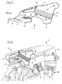
- Fig. 1 shows a section through an inventive air filter housing 1.
- the reference numerals of Fig. 1 apply to the same components for Fig. 2.
- the air filter housing 1 consists of a Rohluftschale 3 and a clean air shell 4, between which a filter element 5, a commercially available air filter, is arranged.
- the Roh Kunststoffschale 3 and the clean air tray 4 are detachably connected to each other at the peripheral edges 3 ', 4'. Between the peripheral edges 3 ', 4', a seal 12 is arranged.
- the raw air shell 3 has a suction region 3 ", which is arranged on the body of the vehicle front 6.
- the body forms in the present case, two air guide elements 6 'in the air intake.
- the forward direction of travel of the motor vehicle is indicated by a double arrow.
- FIG. 2 shows an installation situation for a cut, perspectively illustrated air filter housing 1 in the engine compartment of a motor vehicle.
- the intake area 3 is arranged above a coolant heat exchanger 7.
- the coolant heat exchanger 7 is largely covered by a cooling fan 11.
- Geodetically above the coolant heat exchanger 7 is the intake area 3" of the air filter housing 1.
- the air duct 4 In the perspective view in FIG the air duct 4 "recognizable, through which the clean air leaves the clean air bowl 4.
- an air quantity measuring element 8 in the present case a hot-film air mass meter, is integrated into the air duct 4 ", downstream of the air duct 4", the intake air is conducted further in a pipe 10 in the direction of the internal combustion engine.
- This is at least partially formed in a preferred embodiment as a corrugated pipe.
- the air filter housing 1 arranged according to the invention has a resonator 9, which in the exemplary embodiment is arranged, for example, on the tube 10.
- such resonators with which unwanted suction noise can be damped, can also be arranged on the untreated air shell 3 or on the clean air shell 4.
- hot-wire air mass meters can also be used instead of the hot-film air mass meter.
Landscapes
- Engineering & Computer Science (AREA)
- Chemical & Material Sciences (AREA)
- Combustion & Propulsion (AREA)
- Mechanical Engineering (AREA)
- General Engineering & Computer Science (AREA)
- Manufacturing & Machinery (AREA)
- Physics & Mathematics (AREA)
- Fluid Mechanics (AREA)
- Analytical Chemistry (AREA)
- Filtering Of Dispersed Particles In Gases (AREA)
- Measuring Volume Flow (AREA)
Abstract
Description
- Die Erfindung betrifft eine Anordnung eines Luftfiltergehäuses für eine Brennkraftmaschine im Motorraum eines Kraftfahrzeuges mit den Merkmalen aus dem Oberbegriff des Patentanspruchs 1.
- Sie geht von der europäischen Patentschrift EP 0 823 548 B1 aus, in der eine Anordnung eines Luftfiltergehäuses im Motorraum eines Kraftfahrzeuges beschrieben ist. Der Luftfilter besteht aus einer Rohluftschale und einer Reinluftschale, die lösbar miteinander verbunden sind, wobei ein austauschbarer Ansaugluftfilter zwischen Rohluftschale und Reinluftschale angeordnet ist. Sowohl an die Reinluftschale als auch an die Rohluftschale ist jeweils ein Luftführungskanal angeordnet, durch die von der Brennkraftmaschine angesaugte Luft eintreten, bzw. austreten kann. Die Rohluftschale ist ortsfest an die Karosserie des Kraftfahrzeuges angeordnet.
- Aufgabe der vorliegenden Erfindung ist es, ein gattungsgemäßes Luftfiltergehäuse besonders Platz sparend in den Motorraum eines Kraftfahrzeuges zu integrieren.
- Diese Aufgabe wird durch das Merkmal im kennzeichnenden Teil des Patentanspruchs 1 dadurch gelöst, dass der Ansaugbereich geodätisch oberhalb eines Kühlmittelwärmetauschers der Brennkraftmaschine angeordnet ist und von dem Motorraum vor dem Ansaugbereich zumindest ein Luftleitelement gebildet ist und in dem Luftführungskanal ein Luftmengenmesselement angeordnet ist.
- Durch die erfindungsgemäße Ausgestaltung wird die Luft durch den Ansaugbereich, allgemein Ansaugschnorchel genannt, oberhalb des Kühlmittelwärmetauschers angesaugt. Durch das von der Karosserie gebildete zumindest eine Luftleitelement am Eintritt in das Luftfiltergehäuse, wird die Rohluft in den tiefen Teil des Luftfiltergehäuses umgelenkt, wo Wasser und Grobpartikel ausgeschieden und drainiert werden sodass der Filter weniger verschmutzt, bzw. angefeuchtet wird. Dies ist insbesondere für selbstzündende Brennkraftmaschinen wichtig, da über die der Brennkraftmaschine zugeführte Luftmasse die aktuell notwendige Brennstoffmenge ermittelt wird. Feuchte Ansaugluft kühlt jedoch einen Luftmassenmesser schneller ab als Trockene, wodurch bei feuchter Ansaugluft eine zu große Ansaugluftmasse ermittelt wird und somit eine falsche Brennstoffmenge der Brennkraftmaschine zugeführt wird. Weiter wird über eine Einströmöffnung mit einem Fangkragen die vorgereinigte Rohluft dem Luftfilter zugeführt. Die nach dem Luftfilter gereinigte Luft strömt anschließend zu einem Luftmengenmesselement, das ebenfalls im Luftfiltermodul integriert ist.
- In einer weiteren Ausgestaltungsvariante kann gemäß Patentanspruch 2 in Hauptströmrichtung vor dem Luftmengenmesselement ein weiteres Strömungselement angeordnet sein, wodurch die Luft vor der Luftmengenmessung gleichgerichtet wird und eine genauere und präzisere Messung möglich ist. Zusätzlich wird der Druckverlust durch das Strömungsleitelement zum Luftmengenmesselement verringert und die Anströmverhältnisse des Luftmengenmesselementes verbessert, wodurch die Kennlinie des Luftmengenmesselementes verbessert, d. h. linearisiert wird.
- Gemäß Patentanspruch 3 ist das Luftmengenmesselement ein besonders robuster Heißfilmluftmassensensor.
- Ferner verfügt die Rohluftschale gemäß Patentanspruch 4 über eine Öffnung, durch die die zuvor beschriebene vorab abgeschiedene Feuchtigkeit sowie grobe Schmutzpartikel ausgeschieden werden. Durch diese Maßnahme ist die Wasserschlaggefahr minimiert und die Lebensdauer des Luftfilters verlängert.
- Gemäß Patentanspruch 5 kann an die Rohluftschale und/oder an die Reinluftschale ein zusätzlicher Resonator angeordnet sein. Durch diese Maßnahme werden ungewünschte Geräusche wirkungsvoll gedämpft.
- Die Anordnung gemäß Patentanspruch 6 erlaubt eine schwingungstechnische Entkopplung zwischen Luftfiltergehäuse und Brennkraftmaschine.
- Im Folgenden ist das erfindungsgemäße Luftfiltergehäuse anhand eines bevorzugten Ausführungsbeispieles in zwei Figuren näher erläutert.
- Fig. 1
- zeigt einen Schnitt durch eine erfindungsgemäße Luftfiltergehäuseanordnung,
- Fig. 2
- zeigt die Einbausituation eines geschnittenen Luftfiltergehäuses in dem Motorraum eines Kraftfahrzeuges.
- Fig. 1 zeigt einen Schnitt durch ein erfindungsgemäßes Luftfiltergehäuse 1. Die Bezugszeichen aus Fig. 1 gelten für gleiche Bauteile auch für Fig. 2. Das Luftfiltergehäuse 1 besteht aus einer Rohluftschale 3 und einer Reinluftschale 4, zwischen denen ein Filterelement 5, ein handelsüblicher Luftfilter, angeordnet ist. Die Rohluftschale 3 und die Reinluftschale 4 sind lösbar an deren umlaufenden Rändern 3', 4' miteinander verbunden. Zwischen den umlaufenden Rändern 3', 4' ist eine Dichtung 12 angeordnet. Die Rohluftschale 3 weist einen Ansaugbereich 3" auf. Dieser Ansaugbereich 3" ist an die Karosserie der Kfz-Front 6 angeordnet. Die Karosserie bildet im Bereich der Luftansaugung im vorliegenden Fall zwei Luftleitelemente 6'. Die Vorwärts-Fahrtrichtung des Kraftfahrzeuges ist durch einen Doppelpfeil gekennzeichnet.
- Beim Betrieb der Brennkraftmaschine saugt diese aus der Kfz-Front 6 an den Luftleitelementen 6' vorbei die Ansaugluft, vor dem Filterelement 5 auch Rohluft genannt, an. Der Weg der Ansaugluft ist durch einen Pfeil dargestellt. Nach den Luftleitelementen 6, 6' tritt die Rohluft in den Ansaugbereich 3" ein und anschließend in die Rohluftschale 3. An den Luftleitelementen 6', sowie in der Rohluftschale 3 werden die gröbsten Staubpartikel sowie Feuchtigkeit oder Wassertropfen ausgefällt. Anschließend wird die Ansaugluft durch das Filterelement 5 gesaugt, wo es endgereinigt wird und als so genannte Reinluft in die Reinluftschale 4 eintritt. Weiter wird die Ansaugluft durch einen, in Fig. 1 nicht dargestellten Luftführungskanal 4", in dem ein ebenfalls in Fig. 1 nicht erkennbares Luftmengenmesselement 8 angeordnet ist, weiter in Richtung der Brennkraftmaschine gefördert.
- Fig. 2 zeigt eine Einbausituation für ein geschnittenes, perspektivisch dargestelltes Luftfiltergehäuse 1 im Motorraum eines Kraftfahrzeuges. Erfindungsgemäß ist der Ansaugbereich 3" über einem Kühlmittelwärmetauscher 7 der Brennkraftmaschine angeordnet. Der Kühlmittelwärmetauscher 7 ist größtenteils von einem Kühlgebläse 11 verdeckt. Geodätisch oberhalb des Kühlmittelwärmetauschers 7 befindet sich der Ansaugbereich 3" des Luftfiltergehäuses 1. In der perspektivischen Darstellung in Fig. 2 ist auch der Luftführungskanal 4" erkennbar, durch den die Reinluft die Reinluftschale 4 verlässt.
- In den Luftführungskanal 4" ist wie oben beschrieben ein Luftmengenmesselement 8, im vorliegenden Fall ein Heißfilmluftmassenmesser, integriert. Nach dem Luftführungskanal 4" wird die Ansaugluft weiter in einem Rohr 10 in Richtung Brennkraftmaschine geleitet. Dieses ist zumindest abschnittsweise in einer bevorzugten Ausführungsform als Wellrohr ausgebildet. Des weiteren weist das erfindungsgemäß angeordnete Luftfiltergehäuse 1 einen Resonator 9 auf, der im Ausführungsbeispiel beispielsweise an das Rohr 10 angeordnet ist.
- In weiteren Ausführungsbeispielen können derartige Resonatoren, mit der ungewünschte Ansauggeräusche gedämpft werden, auch an der Rohluftschale 3 oder an der Reinluftschale 4 angeordnet sein. Ferner können anstelle der Heißfilmluftmassenmesser auch Hitzdrahtluftmassenmesser eingesetzt werden.
Claims (6)
- Anordnung eines Luftfiltergehäuses (1) für eine Brennkraftmaschine im Motorraum (2) eines Kraftfahrzeuges, wobei- das Luftfiltergehäuse (1) eine Rohluftschale (3) aufweist, deren umlaufender Rand (3') gegen einen zweiten Rand (4') einer Reinluftschale (4) abgedichtet ist und wobei- ein Filterelement (5) zwischen der Rohluftschale (3) und der Reinluftschale (4) angeordnet ist und- die Rohluftschale (3) einen Ansaugbereich (3") in Richtung einer Kraftfahrzeugfront (6) aufweist und- die Reinluftschale (4) einen Luftführungskanal (4") in Richtung der Brennkraftmaschine aufweist,
dadurch gekennzeichnet, dass- der Ansaugbereich (3") geodätisch oberhalb eines Kühlmittelwärmetauschers (7) der Brennkraftmaschine angeordnet ist und- von dem Motorraum (6) vor dem Ansaugbereich (3") zumindest ein Luftleitelement (6') gebildet ist und- in dem Luftführungskanal (4") ein Luftmengenmesselement (8) angeordnet ist. - Anordnung nach Patentanspruch 1,
dadurch gekennzeichnet, dass im Luftführungskanal (4") in Hauptströmrichtung vor dem Luftmengenmesselement (8) ein Strömungsleitelement angeordnet ist. - Anordnung nach Patentanspruch 1 oder 2,
dadurch gekennzeichnet, dass das Luftmengenmesselement (8) ein Heißfilm- oder ein Hitzdraht-Luftmassensensor ist. - Anordnung nach einem der zuvor genannten Patentansprüche,
dadurch gekennzeichnet, dass die Rohluftschale (3) eine Öffnung zur Abfuhr von einer in der Rohluftschale (3) gesammelten Flüssigkeit und/oder Partikel aufweist. - Anordnung nach einem der zuvor genannten Patentansprüche,
dadurch gekennzeichnet, dass an die Rohluftschale (3) und/oder an die Reinluftschale (4) ein Resonator (9) angeordnet ist. - Anordnung nach einem der zuvor genannten Patentansprüche,
dadurch gekennzeichnet, dass der Luftführungskanal (4") über zumindest ein flexibles, gasführendes Rohr (10) mit der Brennkraftmaschine verbunden ist.
Applications Claiming Priority (1)
| Application Number | Priority Date | Filing Date | Title |
|---|---|---|---|
| DE200410045270 DE102004045270A1 (de) | 2004-09-17 | 2004-09-17 | Anordnung eines Luftfiltergehäuses für eine Brennkraftmaschine im Motorraum eines Kraftfahrzeuges |
Publications (2)
| Publication Number | Publication Date |
|---|---|
| EP1637726A1 true EP1637726A1 (de) | 2006-03-22 |
| EP1637726B1 EP1637726B1 (de) | 2010-12-01 |
Family
ID=35376972
Family Applications (1)
| Application Number | Title | Priority Date | Filing Date |
|---|---|---|---|
| EP20050017571 Expired - Lifetime EP1637726B1 (de) | 2004-09-17 | 2005-08-12 | Anordnung eines Luftfiltergehäuses für eine Brennkraftmaschine im Motorraum eines Kraftfahrzeugs |
Country Status (2)
| Country | Link |
|---|---|
| EP (1) | EP1637726B1 (de) |
| DE (2) | DE102004045270A1 (de) |
Cited By (4)
| Publication number | Priority date | Publication date | Assignee | Title |
|---|---|---|---|---|
| EP2169210A3 (de) * | 2008-08-07 | 2010-05-12 | Mazda Motor Corporation | Motoreinlass-Durchlaufstruktur eines vorderen Fahrzeugkörpers und Verfahren zu deren Bereitstellung |
| EP2206621A1 (de) * | 2009-01-07 | 2010-07-14 | Honda Motor Co., Ltd | Ansaugluft einbringende Struktur für Kraftfahrzeug |
| DE102013007157A1 (de) * | 2013-04-24 | 2014-10-30 | GM Global Technology Operations, LLC (n.d. Ges. d. Staates Delaware) | Luftführungsvorrichtung |
| WO2016135972A1 (ja) * | 2015-02-27 | 2016-09-01 | 本田技研工業株式会社 | 車両の吸気構造 |
Families Citing this family (4)
| Publication number | Priority date | Publication date | Assignee | Title |
|---|---|---|---|---|
| DE102008058431B4 (de) | 2007-11-26 | 2019-10-02 | Denso Corporation | Luftreinigereinheit für Fahrzeug und Ventilatorabdeckung mit dieser |
| US8807113B2 (en) | 2009-05-04 | 2014-08-19 | Ford Global Technologies, Llc | Device and method for integrating an air cleaner into a radiator fan shroud |
| JP6413782B2 (ja) * | 2015-01-19 | 2018-10-31 | スズキ株式会社 | エンジンの吸気装置 |
| DE102017009492A1 (de) | 2017-10-12 | 2019-04-18 | Daimler Ag | Verfahren zur Einstellung einer Motorakustik einer Verbrennungskraftmaschine |
Citations (8)
| Publication number | Priority date | Publication date | Assignee | Title |
|---|---|---|---|---|
| US5059221A (en) * | 1989-08-15 | 1991-10-22 | Siemens-Bendix Automotive Electronics Limited | Integrated air cleaner assembly |
| DE9202785U1 (de) * | 1992-03-03 | 1992-04-23 | Adam Opel AG, 6090 Rüsselsheim | Struktur für die Motorluftansaugung von Brennkraftmaschinen |
| EP0515051A1 (de) * | 1991-05-23 | 1992-11-25 | Ford Motor Company Limited | Luftreiniger für eine Brennkraftmaschine |
| DE4302659C1 (de) * | 1993-01-30 | 1994-04-21 | Daimler Benz Ag | Ansaugluftführung für einen Verbrennungsmotor |
| EP0859145A1 (de) * | 1997-01-23 | 1998-08-19 | Denso Corporation | Luftreiniger für Verbrennungskraftmaschine |
| US5899196A (en) * | 1997-12-19 | 1999-05-04 | Jeffrey S. Melcher | Method and apparatus for supplying warm air to an air intake of an engine |
| EP0995895A2 (de) * | 1998-10-22 | 2000-04-26 | McCORD WINN TEXTRON INC. | Lüftergehäuse und Lufteinlassanordnung |
| EP0823548B1 (de) | 1996-08-09 | 2001-10-04 | Bayerische Motoren Werke Aktiengesellschaft, Patentabteilung AJ-3 | Anordnung eines Luftfiltergehäuses im Motorraum eines Kraftfahrzeuges |
Family Cites Families (2)
| Publication number | Priority date | Publication date | Assignee | Title |
|---|---|---|---|---|
| US5072698A (en) * | 1989-05-30 | 1991-12-17 | Mazda Motor Corporation | Intake apparatus for engine |
| US6736871B1 (en) * | 2002-12-09 | 2004-05-18 | Visteon Global Technologies, Inc. | Integrated filter screen and hydrocarbon adsorber |
-
2004
- 2004-09-17 DE DE200410045270 patent/DE102004045270A1/de not_active Withdrawn
-
2005
- 2005-08-12 DE DE200550010606 patent/DE502005010606D1/de not_active Expired - Lifetime
- 2005-08-12 EP EP20050017571 patent/EP1637726B1/de not_active Expired - Lifetime
Patent Citations (8)
| Publication number | Priority date | Publication date | Assignee | Title |
|---|---|---|---|---|
| US5059221A (en) * | 1989-08-15 | 1991-10-22 | Siemens-Bendix Automotive Electronics Limited | Integrated air cleaner assembly |
| EP0515051A1 (de) * | 1991-05-23 | 1992-11-25 | Ford Motor Company Limited | Luftreiniger für eine Brennkraftmaschine |
| DE9202785U1 (de) * | 1992-03-03 | 1992-04-23 | Adam Opel AG, 6090 Rüsselsheim | Struktur für die Motorluftansaugung von Brennkraftmaschinen |
| DE4302659C1 (de) * | 1993-01-30 | 1994-04-21 | Daimler Benz Ag | Ansaugluftführung für einen Verbrennungsmotor |
| EP0823548B1 (de) | 1996-08-09 | 2001-10-04 | Bayerische Motoren Werke Aktiengesellschaft, Patentabteilung AJ-3 | Anordnung eines Luftfiltergehäuses im Motorraum eines Kraftfahrzeuges |
| EP0859145A1 (de) * | 1997-01-23 | 1998-08-19 | Denso Corporation | Luftreiniger für Verbrennungskraftmaschine |
| US5899196A (en) * | 1997-12-19 | 1999-05-04 | Jeffrey S. Melcher | Method and apparatus for supplying warm air to an air intake of an engine |
| EP0995895A2 (de) * | 1998-10-22 | 2000-04-26 | McCORD WINN TEXTRON INC. | Lüftergehäuse und Lufteinlassanordnung |
Cited By (8)
| Publication number | Priority date | Publication date | Assignee | Title |
|---|---|---|---|---|
| EP2169210A3 (de) * | 2008-08-07 | 2010-05-12 | Mazda Motor Corporation | Motoreinlass-Durchlaufstruktur eines vorderen Fahrzeugkörpers und Verfahren zu deren Bereitstellung |
| US8474558B2 (en) | 2008-08-07 | 2013-07-02 | Mazda Motor Corporation | Engine intake passage structure of front vehicle body |
| EP2206621A1 (de) * | 2009-01-07 | 2010-07-14 | Honda Motor Co., Ltd | Ansaugluft einbringende Struktur für Kraftfahrzeug |
| US8127878B2 (en) | 2009-01-07 | 2012-03-06 | Honda Motor Co., Ltd. | Intake air introducing structure for automobile |
| CN101780763B (zh) * | 2009-01-07 | 2012-08-08 | 本田技研工业株式会社 | 机动车的进气导入结构 |
| DE102013007157A1 (de) * | 2013-04-24 | 2014-10-30 | GM Global Technology Operations, LLC (n.d. Ges. d. Staates Delaware) | Luftführungsvorrichtung |
| WO2016135972A1 (ja) * | 2015-02-27 | 2016-09-01 | 本田技研工業株式会社 | 車両の吸気構造 |
| JPWO2016135972A1 (ja) * | 2015-02-27 | 2017-12-21 | 本田技研工業株式会社 | 車両の吸気構造 |
Also Published As
| Publication number | Publication date |
|---|---|
| DE502005010606D1 (de) | 2011-01-13 |
| DE102004045270A1 (de) | 2006-03-23 |
| EP1637726B1 (de) | 2010-12-01 |
Similar Documents
| Publication | Publication Date | Title |
|---|---|---|
| EP2029976B1 (de) | Massenstromsensorvorrichtung mit einem strömungsführenden kanal | |
| EP3044451B1 (de) | Luftfilter | |
| EP1127250A1 (de) | Vorrichtung zur messung wenigstens eines parameters eines strömenden mediums | |
| EP1637726B1 (de) | Anordnung eines Luftfiltergehäuses für eine Brennkraftmaschine im Motorraum eines Kraftfahrzeugs | |
| DE102004024466A1 (de) | Kraftstoffmodul | |
| DE10245965B4 (de) | Vorrichtung zur Bestimmung wenigstens eines Parameters eines in einer Leitung strömenden Mediums | |
| DE10246069A1 (de) | Vorrichtung zur Bestimmung wenigstens eines Parameters eines in einer Leitung strömenden Mediums | |
| DE112012004149B4 (de) | Feuchtigkeitsmessvorrichtung | |
| DE102008049843B4 (de) | Luftmassensensor | |
| DE102020205591B4 (de) | Ansaugstruktur eines Fahrzeugs und Verfahren zum Befestigen eines Nippels an der Ansaugstruktur | |
| EP1340056A1 (de) | Luftstrommesser mit vorrichtung zur abscheidung femdpartikel | |
| DE202006019335U1 (de) | Feinstaub-Absaugvorrichtung in einem Fahrzeug | |
| EP1210565B1 (de) | Verwendung eines strömungsgleichrichters als kondensationsfalle für eine flüssigkeit in einer gasströmung | |
| EP2169209B1 (de) | Anordnung einer Luftmassen-Durchflussmesseinrichtung in einem Ansaugsystem einer Brennkraftmaschine | |
| DE10209132A1 (de) | Ansaugvorrichtung für Kaltluft | |
| DE102007034518A1 (de) | Luftfilter für eine Luftsauganlage einer mehrzylindrischen Brennkraftmaschine | |
| EP3737919B1 (de) | Messanordnung zur bestimmung eines parameters eines durch einen fluidströmungskanal strömenden fluiden mediums sowie fluidströmungskanal mit einer solchen messanordnung | |
| DE102008061538A1 (de) | Kanalanordnung zum Führen von Prozessluft zu einer Verbrennungskraftmaschine | |
| DE10316652B4 (de) | Luftfilter für eine Brennkraftmaschine | |
| EP1591653B1 (de) | Luftfilterpatrone für ein Lufteinlasssystem einer Brennkraftmaschine | |
| DE102018129957B4 (de) | Kraftfahrzeug | |
| DE112019006650T5 (de) | Luftdurchflussmessvorrichtung | |
| EP3855024B1 (de) | Absauganordnung für einen zentrifugalluftfilter | |
| DE102018112487A1 (de) | Verfahren zum Betreiben eines Antriebssystems eines Kraftfahrzeugs, Antriebssystem und Kraftfahrzeug | |
| DE102007035303A1 (de) | Kanalanordnung zum Führen von Prozessluft zu einer Verbrennungskraftmaschine |
Legal Events
| Date | Code | Title | Description |
|---|---|---|---|
| PUAI | Public reference made under article 153(3) epc to a published international application that has entered the european phase |
Free format text: ORIGINAL CODE: 0009012 |
|
| AK | Designated contracting states |
Kind code of ref document: A1 Designated state(s): AT BE BG CH CY CZ DE DK EE ES FI FR GB GR HU IE IS IT LI LT LU LV MC NL PL PT RO SE SI SK TR |
|
| AX | Request for extension of the european patent |
Extension state: AL BA HR MK YU |
|
| RIN1 | Information on inventor provided before grant (corrected) |
Inventor name: WIMMER, RUDOLF Inventor name: SCHOBER, MARTIN |
|
| 17P | Request for examination filed |
Effective date: 20060729 |
|
| 17Q | First examination report despatched |
Effective date: 20060824 |
|
| AKX | Designation fees paid |
Designated state(s): DE FR GB IT |
|
| GRAP | Despatch of communication of intention to grant a patent |
Free format text: ORIGINAL CODE: EPIDOSNIGR1 |
|
| GRAS | Grant fee paid |
Free format text: ORIGINAL CODE: EPIDOSNIGR3 |
|
| GRAA | (expected) grant |
Free format text: ORIGINAL CODE: 0009210 |
|
| AK | Designated contracting states |
Kind code of ref document: B1 Designated state(s): DE FR GB IT |
|
| REG | Reference to a national code |
Ref country code: GB Ref legal event code: FG4D Free format text: NOT ENGLISH |
|
| REF | Corresponds to: |
Ref document number: 502005010606 Country of ref document: DE Date of ref document: 20110113 Kind code of ref document: P |
|
| PLBE | No opposition filed within time limit |
Free format text: ORIGINAL CODE: 0009261 |
|
| STAA | Information on the status of an ep patent application or granted ep patent |
Free format text: STATUS: NO OPPOSITION FILED WITHIN TIME LIMIT |
|
| 26N | No opposition filed |
Effective date: 20110902 |
|
| REG | Reference to a national code |
Ref country code: DE Ref legal event code: R097 Ref document number: 502005010606 Country of ref document: DE Effective date: 20110902 |
|
| REG | Reference to a national code |
Ref country code: FR Ref legal event code: PLFP Year of fee payment: 12 |
|
| REG | Reference to a national code |
Ref country code: FR Ref legal event code: PLFP Year of fee payment: 13 |
|
| REG | Reference to a national code |
Ref country code: FR Ref legal event code: PLFP Year of fee payment: 14 |
|
| P01 | Opt-out of the competence of the unified patent court (upc) registered |
Effective date: 20230502 |
|
| PGFP | Annual fee paid to national office [announced via postgrant information from national office to epo] |
Ref country code: DE Payment date: 20240801 Year of fee payment: 20 |
|
| PGFP | Annual fee paid to national office [announced via postgrant information from national office to epo] |
Ref country code: GB Payment date: 20240822 Year of fee payment: 20 |
|
| PGFP | Annual fee paid to national office [announced via postgrant information from national office to epo] |
Ref country code: FR Payment date: 20240821 Year of fee payment: 20 |
|
| PGFP | Annual fee paid to national office [announced via postgrant information from national office to epo] |
Ref country code: IT Payment date: 20240830 Year of fee payment: 20 |
|
| REG | Reference to a national code |
Ref country code: DE Ref legal event code: R071 Ref document number: 502005010606 Country of ref document: DE |
|
| REG | Reference to a national code |
Ref country code: GB Ref legal event code: PE20 Expiry date: 20250811 |