EP1637059A2 - Installation de lave-vaiselle - Google Patents
Installation de lave-vaiselle Download PDFInfo
- Publication number
- EP1637059A2 EP1637059A2 EP05019186A EP05019186A EP1637059A2 EP 1637059 A2 EP1637059 A2 EP 1637059A2 EP 05019186 A EP05019186 A EP 05019186A EP 05019186 A EP05019186 A EP 05019186A EP 1637059 A2 EP1637059 A2 EP 1637059A2
- Authority
- EP
- European Patent Office
- Prior art keywords
- rinse
- storage tank
- water
- spray nozzles
- cleaning
- Prior art date
- Legal status (The legal status is an assumption and is not a legal conclusion. Google has not performed a legal analysis and makes no representation as to the accuracy of the status listed.)
- Granted
Links
Images
Classifications
-
- A—HUMAN NECESSITIES
- A47—FURNITURE; DOMESTIC ARTICLES OR APPLIANCES; COFFEE MILLS; SPICE MILLS; SUCTION CLEANERS IN GENERAL
- A47L—DOMESTIC WASHING OR CLEANING; SUCTION CLEANERS IN GENERAL
- A47L15/00—Washing or rinsing machines for crockery or tableware
- A47L15/24—Washing or rinsing machines for crockery or tableware with movement of the crockery baskets by conveyors
- A47L15/247—Details specific to conveyor-type machines, e.g. curtains
-
- A—HUMAN NECESSITIES
- A47—FURNITURE; DOMESTIC ARTICLES OR APPLIANCES; COFFEE MILLS; SPICE MILLS; SUCTION CLEANERS IN GENERAL
- A47L—DOMESTIC WASHING OR CLEANING; SUCTION CLEANERS IN GENERAL
- A47L15/00—Washing or rinsing machines for crockery or tableware
- A47L15/24—Washing or rinsing machines for crockery or tableware with movement of the crockery baskets by conveyors
- A47L15/241—Washing or rinsing machines for crockery or tableware with movement of the crockery baskets by conveyors the dishes moving in a horizontal plane
Definitions
- the invention relates to a dishwashing machine, comprising at least one conveyor dishwasher, preferably a conveyor dishwasher or a basket conveyor dishwasher, according to the preamble of claim 1.
- Prior art conveyor dishwashers include a dishwashing apparatus and recirculation circuits having elements for heating and / or purifying water and / or mixing different water streams to thereby refresh more polluted water with less polluted water.
- a dishwasher for example, shows the publication of a summary "Abstract of Invention" of the Russian patent RU 2 150 228 C1.
- conveyor ware washer There are two types of conveyor ware washer.
- the one type are tape washers (flight-type goods washers), in which the conveyor belt has holding elements for holding the dishes to be cleaned.
- the other type are rack-conveyor ware washers, in which a transport mechanism transports baskets containing the dishes.
- the conveyor belt or the transport mechanism is provided with a plurality of intermediate spaces or passage openings through which water sprayed onto the dishes can drain downwards.
- Dishwashers are not only suitable for cleaning dishes in the form of plates, cups and bowls, but also for cleaning dishes in the form of spoons, knives and forks and for cleaning trays and for cleaning other objects used in catering establishments, especially in hotels , Restaurants and canteens.
- the term "crockery" is used to represent all objects which can be cleaned by a dishwasher in order to simplify the description of the invention.
- the object of the invention is to solve the problem of designing a dishwashing machine which contains at least one conveyor dishwasher in such a way that the cleaning operation of the dishes becomes more independent of the provision of water for the cleaning process.
- a particular embodiment of the invention relates to a dishwashing machine comprising at least one conveyor dishwasher, preferably a conveyor dishwasher or a basket conveyor dishwasher, characterized in that the at least one conveyor dishwasher is divided into a dishwashing device and a water treatment station arranged spatially separate therefrom, and at least one recirculation circuit is formed, in which water is recirculated from the water treatment station to the dishwashing device and back again, the recirculation circuit in the dishwashing device having spray nozzles for spraying water onto the dishes and at least one water discharge opening for recirculating sprayed water to the water treatment station.
- the water may be treated separately from the dishwashing apparatus, for example, cleaned, heated, pumped and / or altered Mixing water of different quality and / or by mixing water with other liquids or with lettermittein.
- the water treatment station preferably contains a sieve device and / or a membrane filter device.
- the dishwashing device contains a plurality, for example two, rinsing zones, the water treatment station having a screening device for the first rinsing zone and a membrane filter device for the second rinsing zone.
- the screening device comprises a rotating screen cylinder, through which the water is passed, and a solids discharge device for discharging solids (dirt) from the water is arranged inside the screen cylinder.
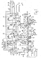
- Figure 1 schematically shows a dishwasher according to the invention, without the invention being limited to the illustrated number of individual elements, areas or zones.
- the water treatment station described below may be configured in various ways for one or more or all of the functions described below, such as, in particular, cleaning of the effluent from the at least one dishwashing device by filtering, screening, flushing and / or mechanically discharging solids and other impurities from the device Water and / or partial removal of dirty water and / or diluting dirty water with fresh water or with less contaminated, already used water, and / or heating the water Water before being recirculated from the water treatment station to the dishwashing device.
- the treatment of the water may be to divide a pump assembly having a plurality of pumps for distributing the water among a plurality of dishwashing devices and / or different cleaning zones and / or different rinse zones of one or more dishwashing devices.
- the dishwasher according to the invention described below with reference to FIG. 1 is optimized by a multiplicity of the aforementioned features.
- FIG. 1 shows a dishwashing machine with a dishwashing device 2 and with a water treatment station 4 spatially separate from it.
- the water treatment station 4 is preferably arranged at least one floor lower than the dishwashing device 2.
- the floors can be separated by a building ceiling 6 or an intermediate floor.
- the dishwashing device 2 and the water treatment station 4 together form a conveyor dishwasher (conveyor ware washer) in the form of a rack conveyor machine (rack-conveyor ware washer) or preferably according to FIG. 1 in the form of a flight-type ware washer.
- the dishwashing device 2 contains at least one cleaning zone and then at least one rinsing zone.
- the dishwashing apparatus 2 shown in FIG. 1 in succession has a first dishwashing zone 8, a second dishwashing zone 10, a third dishwashing zone 12, a first dishwashing zone 14 and a second dishwashing zone 16 in the dishwashing direction. Dishes are transported by an endless conveyor belt (conveyor) 18 through said zones 8 to 16.
- zones 8 to 16 are nozzles for spraying water on the dishes, for example, above the conveyor belt 18 in the cleaning zones 8, 10 and 12 upper spray nozzles 20 and in the rinse zones 14 and 16 upper spray nozzles 21, 22, 23, and between upper run 24 and lower run 26 of the conveyor belt 18 arranged lower nozzles 28 in the Cleaning zones 8, 10 and 12, and lower nozzles 29, 30, 31 in the rinse zones 14 and 16.
- each of the zones there is a water collecting floor 32, each having at least one water discharge opening 34 in each of the cleaning zones 8, 10 and 12 and having a water discharge opening 36 in the first rinse zone 14, to which the sprayed rinse water from both rinse zones 14 and 16 is inclined Zone bottom drains off by gravity.
- All of the aforementioned nozzles in the cleaning zones 8, 10 and 12 and in the rinse zones 14 and 16 direct the water sprayed by them against the dishes to be cleaned or rinsed.
- a valve arrangement 46 arranged in the fresh water supply line 40 may be located at the location of the dishwashing device 2 or preferably at the location of the water treatment station 4.
- a water supply 48 for the supply of demineralized water includes a valve assembly 50 and is connected to a heat exchange line 51 which extends through the upper spray nozzles 21, 22, 23 through both rinsing zones 14 and 16 so that the demineralized water flowing through it is heated by the water vapor rising in the rinsing zones 14 and 16.
- the demineralized water flows to the heat exchanger conduit 51 through a heater 52 in the form of an electric heater or a heat exchanger (also called "booster") and is heated therein before being discharged from the lower and upper spray nozzles 31 and 23 of the second (last) rinse zone 16 is sprayed on the cleaned dishes.
- the valve arrangement 50 of the water supply line 48 may be located at the location of the dishwashing device 2 or preferably at the location of the water treatment station 4.
- a second rinse water storage tank 56 receives by gravity (or a pump) via a membrane filter 58 rinse water from the first rinse water storage tank 44.
- the second rinse water storage tank 56 has a water overflow 60, from which overflowing water through an overflow pipe 63 in the first Rinse water storage tank 44 can flow back.
- a first rinse water pump assembly 62 is connected in the water treatment station 4 with its suction side to a water outlet 64 of the first rinse water storage tank 44 and connected with its pressure side to the upstream beginning of a flow line 66, the downstream end of the first in the transport direction 65 of the harness lower and upper spray nozzles 29 and 21 of the first rinse zone 14 is connected.
- the first rinse water pump assembly 62 preferably consists of a working pump 67, which has a sufficient for the promotion of the rinse water through the flow line 66 delivery capacity, and a parallel connected and optionally switchable reserve pump 68, which also one for the promotion of the rinse water through the flow line 66 has sufficient delivery capacity and thereby completely take over their function in case of failure of the operating pump 67.
- a second flow line 70 is connected at its upstream start to the pressure side of a second rinse water pump assembly 72 whose suction side is connected to an outlet 74 of the second rinse water storage tank 56.
- the second supply line 70 is connected at its downstream end via a heater 76 to the lower 30 and the upper 22 spray nozzles, which are arranged in the crockery transport direction 65 between the first and last spray nozzles 21, 29, 23 and 31 of the two rinse zones 14 and 16.
- the heater 76 may be a heat exchanger or electric heater (booster).
- the two heaters 52 and 76 of the two rinse zones 14 and 16 are preferably arranged in the dishwashing device 2 to avoid heat losses, but according to another embodiment may also be arranged in the water treatment station 4.
- the second rinse water pump assembly 72 may consist of a single pump, but consists in the preferred embodiment of a working pump 77 and a parallel connected to them backup pump 78, which latter is optionally switchable when the operating pump 77 fails due to defect or maintenance.
- the operation pump 77 and the reserve pump 78 each have a capacity sufficient for the conveyance of the purge water.
- the first rinse water storage tank 44 preferably has a water overflow 80, from which water can flow through an overflow pipe 83 into a second cleaning water storage tank 84.
- the second cleaning water storage tank 84 fresh water, preferably hot water, via a valve assembly 86 and a fresh water supply line 88 are supplied.
- An outlet 90 of the second scrubbing water storage tank 84 is connected via a second scrubbing water pump assembly 92 to the upstream end of a flow line 94, which branches to a branch 96 via parallel flow lines 98-1, 98-2, 98-3 and 98-4 is fluidly connected to the upper and lower spray nozzles 20 and 28 of the cleaning zones 10 and 12.
- the branch 96 of the feed line 94 could be arranged directly in the water treatment station 4 instead of in the dishwashing apparatus 2 on the pressure side of the second cleaning water pump assembly 92.
- the second cleaning water pump assembly 92 preferably includes two operating pumps 102 and 104, which are connected in parallel with each other and each of which has sufficient capacity to one of the two cleaning zones Supply 10 and 12 with cleaning water.
- a reserve pump 106 is connected in parallel, which is optionally switchable, if one of the operating pumps 102 or 104 fails.
- the reserve pump 106 has the same pump capacity as one of the other two pumps.
- a cleaning water line 108 is connected between the pressure side of the second cleaning water pump assembly 92 and the distribution point 96, the purpose of which will be described later.
- the second cleaning water storage tank 84 has a water overflow device 120 from which water from the second cleaning water storage tank 84 can flow via an overflow pipe 122 into a first cleaning water storage tank 124 provided with an overflow device 130, through which water passes through an overflow pipe 132 can drain.
- the first cleaning water storage tank 124 is preferably provided with a drainage drain 134.
- the first cleaning water storage tank 124 fresh water, preferably hot water, via a valve assembly 136 of a fresh water supply line 138 are supplied.
- An output 140 of the first cleaning water storage tank 124 is connected via a first cleaning water pump assembly 142 to the upstream end of a feed line 146 which is split at a branch point 148 onto two parallel feed line branches 146-1 and 146-2 which are adjacent to the upper one Spray nozzles 20 and the lower spray nozzles 28 of the first cleaning zone 8 are connected.
- the branching point 148 can be arranged in the dishwashing device 2 according to FIG. 1 or, according to an embodiment not shown, in the water treatment station 4 on the pressure side of the first cleaning water pumping arrangement 142.
- the first cleaning water pump assembly 142 preferably consists of an operating pump 152 and connected to it in parallel and optionally switchable reserve pump 154. Both pumps 152 and 154 are on the promotion of the Cleaning water in the first cleaning zone 8 required delivery capacity designed so that in case of failure or maintenance, the reserve pump 154 can be turned on in case of failure of the operating pump 152, so that even in such a case, the cleaning operation in the cleaning zone 8 can be maintained unchanged ,
- the water discharge opening 34 of the first cleaning zone 8 is connected in fluid communication with a first screening device 170 via a return line 172.
- the cleaning water purified by the first sieving device 170 flows into the first cleaning water storage tank 124.
- the Wasserab technologicalö réelleen 34 of the second and the third cleaning zone 10 and 12 are each connected via a return line 160 or 162, which may be connected to a common return line 164 together, with a second screening device 170 fluidly connected, with contaminants are held by the screen and the cleaning water after the sieve device flows into the second cleaning water storage tank 84.
- the sieve devices 170 and 174 are preferably rotary sieve devices which have a rotating screen cylinder 176 and 178, respectively, in whose interior the cleaning water of the return line 172 or 164 is directed. Cleaning water of the cleaning water pipe 108 is guided from outside to inside through the screen cylinders 176 and 178, respectively.
- a conveying element preferably a screw 180 or 182 for discontinuous or preferably continuous discharge of solids from the cleaning water, which is located in the screen cylinder.
- the discharged solid is indicated in Figure 1 with 184 and 186 and shown schematically by an arrow.
- the second cleaning water storage tank 84 and / or the first cleaning water storage tank 124 is preferably in each case a heating source 190, for example, a heat exchanger or an electric heater.
- the preferred embodiment of the invention shown in FIG. 1 includes the following recirculation cycles: a first recirculation circuit in which the supply line 146 and the supply line sections 146-1, 146-2, furthermore the return line 172, the first screening device 170, the first cleaning water Storage tank 124 and the first cleaning water pump assembly 142 are integrated. Further, a second recirculation circuit is provided, which the supply lines or feed line branches 94, 98-1, 98-2, 98-3, 98-4, the return lines 160, 162, 164, the second screening device 174, the second cleaning water storage tank 84th , and the second cleaning water pump assembly 92 includes.
- a third recirculation circuit contains the supply line 66, the return line 42, the first rinse water storage tank 44 and the first rinse water pump assembly 62.
- the last in the transport direction 65 of the harness fourth, recirculation circuit includes the supply line 70, in turn, the return line 42 and turn the first Rinse water storage tank 44, the membrane filter 58, the second rinse water storage tank 56, and the second rinse water pump assembly 72.
- a particular advantage of the invention is that not only a dishwashing device 2 can be connected to the water treatment station 4, but that two or more dishwashing devices 2 can be connected to the single water treatment station 4. This can be done via additional flow lines and return lines, which are connected to the described storage tanks 124, 84, 44 and 56 and / or to the described screening devices 170 and 174 in terms of flow, or via parallel branches of the described flow lines and the described return lines, using the For this purpose, only valves or other shut-off elements 202, 204, 206, 208, 210, 212, 214, 216, 218 or 220 are required in the flow lines or the parallel branches. Each of these dishwashing devices 2 together with the common water treatment station 4 forms its own conveyor dishwashing machine.
- the Water treatment station 4 for each dishwashing device 2 is a separate pump or pump group corresponding to the described pump assemblies 72, 62, 92 and 142.
- each pumping arrangement includes at least as many operating pumps 77, 67, 102 and 152, respectively, as dishwashing devices 2 are provided, so that in the event of failure of such a pump, only one of these dishwashing devices 2 is affected and this affected dishwashing device with the reserve pump 78, 68 , 106, 154 of the pump assembly in question can continue to operate.
- each pumping arrangement contains at least one operating pump and one reserve pump; that in the presence of two dishwashing devices 2, each pumping arrangement contains at least two operating pumps and one reserve pump; that, when using three dishwashing devices 2, each pumping arrangement includes three operating pumps and one standby pump; and so on.
- the pump capacity which is necessary for the reserve case, reduced to a single reserve pump at each pump assembly.
- two or more reserve pumps of an operating pump or of a group of operating pumps to be connected in parallel and to be optionally switchable.
- the invention particularly relates to commercial dishwashers.
- the inventive idea to arrange additional spray nozzles 22 and 30 between the spray nozzles 23, 31 of the last rinse zone 16 and the spray nozzles 21, 29 of the first rinse zone 14 in the tray transport direction 65 and to supply these additional spray nozzles 22 and 30 with a pre-used rinse liquid filtered by a membrane filter 58, can be used not only for dishwashers, in which a water treatment station 4 is arranged spatially separated from a dishwashing device 2, but also for conveyor dishwashers in the form of tape dishwashers and in the form of Korbtransport Schememaschinen, in which the dishwashing apparatus and the water treatment station integrated without spatial separation in the conveyor dishwasher are.
- This inventive idea can be realized at least by the following embodiments:
- Dishwashing machine comprising at least one conveyor dishwasher in the form of a belt conveyor dishwasher or a basket conveyor dishwasher, the conveyor dishwasher comprising at least one cleaning zone 8, 10, 12 with spray nozzles 20, 28 for spraying cleaning water onto the dishes; at least a first rinse zone 14 with spray nozzles 21, 29 for spraying rinse water onto the dishes; a final rinse zone 16 as a final rinse zone with spray nozzles 23, 31 for spraying rinse water onto the dishes; a transporting device 18 for transporting dishes through zones 8, 10, 12, 14 and 16; characterized by additional spray nozzles 22, 30 arranged in a tray transporting direction 65 between the spray nozzles 21, 29 of the first rinse zone 14 and the spray nozzles 23, 31 of the rinse zone 16 for spraying rinse water onto the dishes; a rinse water storage tank 44 for receiving the rinse water sprayed from the spray nozzles 23, 31 of the rinse zone 16, for receiving the rinse water sprayed from the additional spray nozzles 22, 30, and for receiving the rinse water sprayed from the spray nozzles 21, 29 of the first rinse zone 14;
- Dishwashing system characterized in that in the additional Spülwasservorlaufweg 58, 56, 72, 70, 76, an additional rinse water storage tank 56 in the Spülwasserströmungsweg between the membrane filter 58 and the pump 77, 78 is arranged.
- Dishwashing system characterized in that the additional rinse water storage tank 56 has an overflow 60, via which rinse water can flow back into the rinse water storage tank 44.
- Dishwasher according to at least one of the preceding embodiments, characterized in that in the additional Spülwasservorlaufweg 58, 56, 72, 70, 76 downstream of the pump 77, 78, a heater 76 is arranged to heat the rinse water.
- Dishwashing plant characterized in that at least one cleaning water storage tank 84, 124 is provided for receiving the cleaning water sprayed from the spray nozzles 20, 28 from at least one of the cleaning zones 8, 10, 12; in that at least one cleaning water supply line 92, 94 and 142, 146 with at least one pump 102, 104, 106 and 152, 154 from the at least one cleaning water storage tank 84, 124 to the spray nozzles 20, 28 of the at least a cleaning zone 8, 10, 12 is provided to these cleaning nozzles 20, 28 supply cleaning water from the cleaning water storage tank 84, 124, so that at least one cleaning water Rezirkulationsniklauf from the cleaning water storage tank 84, 124 to the spray nozzles 20, 28 of the respective cleaning zone 8, 10, 12 and back to the cleaning water storage tank 84, 124 is formed.
- Dishwashing system characterized in that the rinse water storage tank 44 and the at least one cleaning water storage tank 84, 124 are each provided with a water overflow 80, 120, through which water against the Geschirrtransportides 65 can flow from storage tank to storage tank, starting from the rinse water storage tank 44 to the last in the crockery transport direction 65 cleaning water storage tank 120th
Landscapes
- Washing And Drying Of Tableware (AREA)
- Cleaning By Liquid Or Steam (AREA)
Priority Applications (1)
| Application Number | Priority Date | Filing Date | Title |
|---|---|---|---|
| DE202005015387U DE202005015387U1 (de) | 2004-09-18 | 2005-09-03 | Geschirrspülanlage |
Applications Claiming Priority (1)
| Application Number | Priority Date | Filing Date | Title |
|---|---|---|---|
| DE102004045445A DE102004045445A1 (de) | 2004-09-18 | 2004-09-18 | Geschirrspülanlage |
Publications (3)
| Publication Number | Publication Date |
|---|---|
| EP1637059A2 true EP1637059A2 (fr) | 2006-03-22 |
| EP1637059A3 EP1637059A3 (fr) | 2008-07-23 |
| EP1637059B1 EP1637059B1 (fr) | 2009-08-05 |
Family
ID=35474724
Family Applications (2)
| Application Number | Title | Priority Date | Filing Date |
|---|---|---|---|
| EP05018980.2A Expired - Fee Related EP1637058B1 (fr) | 2004-09-18 | 2005-09-01 | Machine à laver la vaisselle |
| EP05019186A Expired - Fee Related EP1637059B1 (fr) | 2004-09-18 | 2005-09-03 | Installation de lave-vaiselle |
Family Applications Before (1)
| Application Number | Title | Priority Date | Filing Date |
|---|---|---|---|
| EP05018980.2A Expired - Fee Related EP1637058B1 (fr) | 2004-09-18 | 2005-09-01 | Machine à laver la vaisselle |
Country Status (3)
| Country | Link |
|---|---|
| US (2) | US20060060230A1 (fr) |
| EP (2) | EP1637058B1 (fr) |
| DE (2) | DE102004045445A1 (fr) |
Cited By (1)
| Publication number | Priority date | Publication date | Assignee | Title |
|---|---|---|---|---|
| DE102007024799A1 (de) | 2007-05-26 | 2008-11-27 | Premark Feg L.L.C., Wilmington | Gewerbliche Geschirrspülmaschine |
Families Citing this family (9)
| Publication number | Priority date | Publication date | Assignee | Title |
|---|---|---|---|---|
| FR2884690B1 (fr) | 2005-04-22 | 2007-06-29 | Premark Feg Llc | Four professionnel grande cuisine a eclairage perfectionne |
| DE102005035764A1 (de) * | 2005-07-29 | 2007-02-01 | Premark Feg L.L.C., Wilmington | Transportgeschirrspülmaschine und Betriebsverfahren hierfür |
| DE102009010182A1 (de) * | 2009-02-23 | 2010-08-26 | Krones Ag | Vorrichtung zum Reinigen von Behältern |
| US10722095B1 (en) | 2013-12-05 | 2020-07-28 | Chris Gilreath | Water conserving cleaning system, apparatus and method |
| US9782053B2 (en) | 2013-12-05 | 2017-10-10 | Christopher J. Gilreath | Water conserving cleaning system, apparatus, and method |
| CN104941939A (zh) * | 2015-05-25 | 2015-09-30 | 浙江明泉工业涂装有限公司 | 节水型涂装前处理清洗装置 |
| CN104959337A (zh) * | 2015-05-25 | 2015-10-07 | 浙江明泉工业涂装有限公司 | 涂装工件逆回流清洗方法 |
| ES2683599T3 (es) * | 2015-06-15 | 2018-09-27 | Rimowa Electronic Tag Gmbh | Bulto |
| KR20210158763A (ko) | 2020-06-24 | 2021-12-31 | 엘지전자 주식회사 | 신발 관리장치 |
Citations (2)
| Publication number | Priority date | Publication date | Assignee | Title |
|---|---|---|---|---|
| RU2150228C1 (ru) | 1998-05-20 | 2000-06-10 | Товарищество с ограниченной ответственностью Фирма "Техника-2000" | Посудомоечная машина |
| JP2003126000A (ja) | 2001-10-22 | 2003-05-07 | Winterhalter Japan Co Ltd | 食器洗浄機及び食器洗浄方法 |
Family Cites Families (50)
| Publication number | Priority date | Publication date | Assignee | Title |
|---|---|---|---|---|
| US1279949A (en) * | 1917-07-25 | 1918-09-24 | Fay L Waterman | Apparatus for separating suspended solids from liquids. |
| US2229610A (en) * | 1936-10-23 | 1941-01-21 | Scott Viner Company | Apparatus for heat treating vegetables prior to canning |
| US2240442A (en) * | 1938-07-18 | 1941-04-29 | Huntley Mfg Co | Cleaning and separating device |
| US2232425A (en) * | 1938-08-17 | 1941-02-18 | Maryland Baking Company Inc | Cone dispenser |
| US2714892A (en) * | 1952-09-20 | 1955-08-09 | Rulon Henderson Inc | Plural-chamber apparatus for treating objects |
| US2962741A (en) * | 1957-04-15 | 1960-12-06 | Albert A Petrillo | Portable electrically operated dish washer |
| DE1766212U (de) * | 1958-02-05 | 1958-05-08 | Krefft A G W | Geschirrspuelmaschine. |
| US3089325A (en) * | 1959-12-10 | 1963-05-14 | Robbins | Dry cleaning system |
| US3049134A (en) * | 1961-09-27 | 1962-08-14 | Detrex Chem Ind | Multi-flight washer or degreaser |
| DE1621679A1 (de) * | 1966-02-04 | 1971-06-09 | Wilhelm Wache Gmbh | Anordnung zur Behandlung von Metallwerkstuecken mit Hilfe von wenigstens zwei verschiedenen Fluessigkeiten |
| FR1527999A (fr) | 1967-04-21 | 1968-06-07 | Csf | Perfectionnement aux dispositifs d'élimination d'échos fixes |
| US3502215A (en) * | 1967-11-27 | 1970-03-24 | Robo Wash Inc | Water reclamation apparatus |
| US3504390A (en) * | 1968-05-08 | 1970-04-07 | Cornell Wing | Apparatus for washing cartons |
| US3598131A (en) * | 1969-08-12 | 1971-08-10 | Adamation Inc | Steam collection system for dishwashing machines |
| DE1956050C3 (de) * | 1969-11-07 | 1978-06-01 | Meiko Maschinen- Und Apparatebau, Ingenieur Oskar Meier Gmbh & Co, 7600 Offenburg | Vorabräumeinrichtung für Speiseplatten |
| US3698407A (en) * | 1971-04-05 | 1972-10-17 | Tore H Noren | Dishwashing machine and dish-conveying table with recirculating flushing trough |
| US3789860A (en) * | 1971-11-05 | 1974-02-05 | Hobart Mfg Co | Method and apparatus for treating dishwasher discharge |
| JPS5227615B2 (fr) * | 1971-12-24 | 1977-07-21 | ||
| US3798860A (en) * | 1972-11-09 | 1974-03-26 | Inter Modul Building Syst Corp | Modular building section |
| US3841116A (en) * | 1972-12-08 | 1974-10-15 | Century Niagara Corp | Multiple automatic washer system |
| US3849197A (en) * | 1973-03-08 | 1974-11-19 | B Sorrentino | Method and apparatus for decontaminating a rinse liquid |
| US3896828A (en) * | 1973-10-23 | 1975-07-29 | Interlake Inc | Treatment of pickle liquor rinse water |
| US3931013A (en) * | 1974-08-30 | 1976-01-06 | G. S. Balkeslee & Co. | Water separator-recirculator for dishwashing machine |
| US4039349A (en) * | 1976-02-17 | 1977-08-02 | Bethlehem Steel Corporation | Method and apparatus for multi-stage rinsing |
| US4076554A (en) * | 1976-11-01 | 1978-02-28 | Weihe Clyde R | Apparatus and method for displaying the cost of operation of a commercial dishwashing machine |
| US4156621A (en) * | 1977-09-28 | 1979-05-29 | American Sterilizer Company | Regeneration of used dishwashing water without chemical additives for sanitizing and spot-free rinse uses |
| US4441340A (en) * | 1982-02-18 | 1984-04-10 | Darryl Kaplan | Energy saving laundry system |
| FR2540720B1 (fr) * | 1983-02-16 | 1986-08-14 | Borel International Jacques | Machine industrielle a laver la vaisselle munie d'un dispositif economiseur de chaleur et de fluide de lavage |
| US4561904A (en) * | 1984-09-21 | 1985-12-31 | Hobart Corporation | Control system and method of controlling a dishwashing machine |
| DE3850254T2 (de) * | 1988-08-29 | 1994-09-29 | Toray Industries | Rotierende Filtertrommel für Fest-Flüssig-Trennung. |
| DE4006620A1 (de) * | 1989-03-03 | 1990-09-06 | Hoshizaki Electric Co Ltd | Geschirrspueler |
| US4941491A (en) * | 1989-04-07 | 1990-07-17 | Automated Cleaning Systems, Inc. | Method and apparatus for cleaning containers |
| US5182008A (en) * | 1991-04-24 | 1993-01-26 | Shelstad Richard J | Filtration assembly |
| US5374356A (en) * | 1992-07-28 | 1994-12-20 | Pall Corporation | Fluid treatment process using dynamic microfiltration and ultrafiltration |
| DE59309256D1 (de) * | 1992-11-16 | 1999-02-11 | Winterhalter Gastronom Gmbh | Geschirrspülmaschine |
| DE4428738A1 (de) * | 1994-08-13 | 1996-02-15 | Meiko Maschinenbau Gmbh & Co | Durchlauf-Geschirrspülmaschine |
| DE4437737A1 (de) * | 1994-10-21 | 1996-04-25 | Guenther Zippel Maschf | Verfahren und Vorrichtung zum Reinigen von Gegenständen |
| US5622196A (en) * | 1996-01-16 | 1997-04-22 | Luongo; Arthur J. | Apparatus for washing objects |
| DE29622760U1 (de) * | 1996-03-02 | 1997-07-17 | Finanziaria Ali S P A | Reinigungsmaschine insbesondere für Geschirr mit einer Nachspülwasserumleitung, die in der Menge verändert werden kann und gesteuert den einzelnen Tanks zugeleitet werden kann, Verwendung des umgeleiteten Wassers für Zwischenspülungen |
| DE19644438C2 (de) * | 1996-10-25 | 1998-11-12 | Premark Feg L L C N D Ges D St | Durchlaufgeschirrspülvorrichtung sowie Verfahren zum Reinigen von Geschirr- und/oder Tabletteilen |
| US6010621A (en) * | 1998-03-11 | 2000-01-04 | Pattee; Harley J. | Oil filter for absorbing free oil from laundry water |
| DE19829650C2 (de) * | 1998-07-02 | 2000-06-08 | Premark Feg Llc | Durchlaufgeschirrspülvorrichtung für Geschirrkörbe und Verfahren zum Betrieb davon |
| DE19836739A1 (de) | 1998-08-13 | 2000-02-17 | Meiko Maschinenbau Gmbh & Co | Geschirrspülmaschine |
| EP0980668A3 (fr) * | 1998-08-18 | 2002-05-22 | Epenhuysen Chemie N.V. | Méthode pour délivrer un liquide, méthode pour générer de la mousse et dispositif mettant en oeuvre une telle méthode |
| DE19913918C1 (de) * | 1999-03-26 | 2000-10-19 | Siemens Ag | Anlage zur Fertigung von Halbleiterprodukten, insbesondere zur Bearbeitung von Wafern |
| US6823878B1 (en) * | 1999-04-22 | 2004-11-30 | Eltek S.P.A. | Household appliance using water, namely a washing machine, with improved device for softening the water |
| US6299775B1 (en) * | 2000-03-17 | 2001-10-09 | Clint R. Elston | Waste and wastewater treatment and recycling system |
| US6328882B1 (en) * | 2000-04-03 | 2001-12-11 | Joel Hl. Rosenblatt | Residential waste water recycling system |
| US6820446B2 (en) * | 2000-05-29 | 2004-11-23 | Sharp Kabushiki Kaisha | Sewage disposal agent, sewage purifier, washing machine with purifier, and sewage purifying method |
| GB0224760D0 (en) * | 2002-10-25 | 2002-12-04 | Jowett E C | Waste water treatment station in shipping container |
-
2004
- 2004-09-18 DE DE102004045445A patent/DE102004045445A1/de not_active Ceased
-
2005
- 2005-09-01 EP EP05018980.2A patent/EP1637058B1/fr not_active Expired - Fee Related
- 2005-09-03 EP EP05019186A patent/EP1637059B1/fr not_active Expired - Fee Related
- 2005-09-03 DE DE502005007831T patent/DE502005007831D1/de active Active
- 2005-09-14 US US11/225,911 patent/US20060060230A1/en not_active Abandoned
- 2005-09-14 US US11/225,982 patent/US7481231B2/en not_active Expired - Fee Related
Patent Citations (2)
| Publication number | Priority date | Publication date | Assignee | Title |
|---|---|---|---|---|
| RU2150228C1 (ru) | 1998-05-20 | 2000-06-10 | Товарищество с ограниченной ответственностью Фирма "Техника-2000" | Посудомоечная машина |
| JP2003126000A (ja) | 2001-10-22 | 2003-05-07 | Winterhalter Japan Co Ltd | 食器洗浄機及び食器洗浄方法 |
Cited By (2)
| Publication number | Priority date | Publication date | Assignee | Title |
|---|---|---|---|---|
| DE102007024799A1 (de) | 2007-05-26 | 2008-11-27 | Premark Feg L.L.C., Wilmington | Gewerbliche Geschirrspülmaschine |
| DE202007018745U1 (de) | 2007-05-26 | 2009-03-12 | Premark Feg L.L.C., Wilmington | Gewerbliche Geschirrspülmaschine |
Also Published As
| Publication number | Publication date |
|---|---|
| EP1637058A3 (fr) | 2009-11-25 |
| DE102004045445A1 (de) | 2006-03-23 |
| EP1637058B1 (fr) | 2014-11-19 |
| US20060060231A1 (en) | 2006-03-23 |
| DE502005007831D1 (de) | 2009-09-17 |
| US20060060230A1 (en) | 2006-03-23 |
| EP1637058A2 (fr) | 2006-03-22 |
| EP1637059A3 (fr) | 2008-07-23 |
| US7481231B2 (en) | 2009-01-27 |
| EP1637059B1 (fr) | 2009-08-05 |
Similar Documents
| Publication | Publication Date | Title |
|---|---|---|
| EP1637059B1 (fr) | Installation de lave-vaiselle | |
| EP1752080B1 (fr) | Lave-vaisselle du type transport comportant des moyens pour réduire la salissure du fluide de lavage | |
| EP1743871B1 (fr) | Traitement des effluents aqueux avec des automates de rinçage et de nettoyage dans plusieurs réservoirs | |
| EP1717518B1 (fr) | Four comprenant une ouverture d'évacuation de l'enceinte et un siphon | |
| DE102012212638C5 (de) | Spülmaschine sowie Verfahren zum Betreiben einer Spülmaschine | |
| EP0838190B1 (fr) | Machine à laver la vaisselle type tunnel et procédé pour nettoyer la vaisselle et/ou les plateaux | |
| EP2252191B1 (fr) | Procédé d'auto-nettoyage d'un lave-vaisselle à avancement automatique et lave-vaisselle à avancement automatique correspondant | |
| DE102005039385A1 (de) | Transport-Geschirrspülmaschine | |
| EP1815779B1 (fr) | Machine à laver la vaisselle à bande | |
| EP2072000B1 (fr) | Lave-vaisselle en forme d'automate de programmation et son procédé de fonctionnement | |
| EP0689791A1 (fr) | Machine à rincer et dispositif de récupération de chaleur des eaux usées | |
| DE102005014353A1 (de) | Transportspülmaschine und Verfahren hierfür | |
| DE102019205919B4 (de) | Wasserführendes Haushaltsgerät und Verfahren zu seinem Betrieb | |
| DE112008000023T5 (de) | Gemüsewaschvorrichtung und -system | |
| DE102014208813A1 (de) | Transportspülmaschine sowie Verfahren zum Betreiben einer Transportspülmaschine | |
| DE102005039140A1 (de) | Transport-Geschirrspülmaschine | |
| WO2012139772A1 (fr) | Machine à laver à transporteur possédant une zone de traitement spéciale | |
| DE102009032964A1 (de) | Verfahren zum Betrieb einer Mehrtankgeschirrspülmaschine | |
| DE202006020580U1 (de) | Gewerbliche Geschirrspülmaschine in Form eines Programmautomaten | |
| AT502037B1 (de) | Verfahren zum reinigen von gegenständen und reinigungssystem | |
| EP2500459B2 (fr) | Procédé et dispositif de lavage, en particulier de pièces de linge | |
| DE202005013348U1 (de) | Geschirrspülanlage | |
| DE202005015387U1 (de) | Geschirrspülanlage | |
| EP2116168B1 (fr) | Dispositif de séparation d'impuretés doté d'un réglage de niveau | |
| EP2964067B1 (fr) | Lave-vaisselle à convoyeur comprenant plusieurs zones de traitement |
Legal Events
| Date | Code | Title | Description |
|---|---|---|---|
| PUAI | Public reference made under article 153(3) epc to a published international application that has entered the european phase |
Free format text: ORIGINAL CODE: 0009012 |
|
| 17P | Request for examination filed |
Effective date: 20050903 |
|
| AK | Designated contracting states |
Kind code of ref document: A2 Designated state(s): AT BE BG CH CY CZ DE DK EE ES FI FR GB GR HU IE IS IT LI LT LU LV MC NL PL PT RO SE SI SK TR |
|
| AX | Request for extension of the european patent |
Extension state: AL BA HR MK YU |
|
| PUAL | Search report despatched |
Free format text: ORIGINAL CODE: 0009013 |
|
| AK | Designated contracting states |
Kind code of ref document: A3 Designated state(s): AT BE BG CH CY CZ DE DK EE ES FI FR GB GR HU IE IS IT LI LT LU LV MC NL PL PT RO SE SI SK TR |
|
| AX | Request for extension of the european patent |
Extension state: AL BA HR MK YU |
|
| RIC1 | Information provided on ipc code assigned before grant |
Ipc: A47L 15/24 20060101AFI20080618BHEP |
|
| 17Q | First examination report despatched |
Effective date: 20080905 |
|
| GRAP | Despatch of communication of intention to grant a patent |
Free format text: ORIGINAL CODE: EPIDOSNIGR1 |
|
| AKX | Designation fees paid |
Designated state(s): DE FR GB IT |
|
| GRAS | Grant fee paid |
Free format text: ORIGINAL CODE: EPIDOSNIGR3 |
|
| GRAA | (expected) grant |
Free format text: ORIGINAL CODE: 0009210 |
|
| AK | Designated contracting states |
Kind code of ref document: B1 Designated state(s): DE FR GB IT |
|
| REG | Reference to a national code |
Ref country code: GB Ref legal event code: FG4D Free format text: NOT ENGLISH |
|
| REF | Corresponds to: |
Ref document number: 502005007831 Country of ref document: DE Date of ref document: 20090917 Kind code of ref document: P |
|
| PLBE | No opposition filed within time limit |
Free format text: ORIGINAL CODE: 0009261 |
|
| STAA | Information on the status of an ep patent application or granted ep patent |
Free format text: STATUS: NO OPPOSITION FILED WITHIN TIME LIMIT |
|
| 26N | No opposition filed |
Effective date: 20100507 |
|
| PGFP | Annual fee paid to national office [announced via postgrant information from national office to epo] |
Ref country code: GB Payment date: 20120925 Year of fee payment: 8 |
|
| PGFP | Annual fee paid to national office [announced via postgrant information from national office to epo] |
Ref country code: IT Payment date: 20120921 Year of fee payment: 8 Ref country code: FR Payment date: 20121001 Year of fee payment: 8 |
|
| PGFP | Annual fee paid to national office [announced via postgrant information from national office to epo] |
Ref country code: DE Payment date: 20120927 Year of fee payment: 8 |
|
| GBPC | Gb: european patent ceased through non-payment of renewal fee |
Effective date: 20130903 |
|
| REG | Reference to a national code |
Ref country code: DE Ref legal event code: R119 Ref document number: 502005007831 Country of ref document: DE Effective date: 20140401 |
|
| REG | Reference to a national code |
Ref country code: FR Ref legal event code: ST Effective date: 20140530 |
|
| PG25 | Lapsed in a contracting state [announced via postgrant information from national office to epo] |
Ref country code: GB Free format text: LAPSE BECAUSE OF NON-PAYMENT OF DUE FEES Effective date: 20130903 |
|
| PG25 | Lapsed in a contracting state [announced via postgrant information from national office to epo] |
Ref country code: FR Free format text: LAPSE BECAUSE OF NON-PAYMENT OF DUE FEES Effective date: 20130930 Ref country code: IT Free format text: LAPSE BECAUSE OF NON-PAYMENT OF DUE FEES Effective date: 20130903 Ref country code: DE Free format text: LAPSE BECAUSE OF NON-PAYMENT OF DUE FEES Effective date: 20140401 |