EP1635107B1 - Procédé et dispositif de commande d'une fonction de sécurité d'une machine - Google Patents
Procédé et dispositif de commande d'une fonction de sécurité d'une machine Download PDFInfo
- Publication number
- EP1635107B1 EP1635107B1 EP05014464A EP05014464A EP1635107B1 EP 1635107 B1 EP1635107 B1 EP 1635107B1 EP 05014464 A EP05014464 A EP 05014464A EP 05014464 A EP05014464 A EP 05014464A EP 1635107 B1 EP1635107 B1 EP 1635107B1
- Authority
- EP
- European Patent Office
- Prior art keywords
- machine
- movement
- control
- evaluation unit
- accordance
- Prior art date
- Legal status (The legal status is an assumption and is not a legal conclusion. Google has not performed a legal analysis and makes no representation as to the accuracy of the status listed.)
- Active
Links
- 238000000034 method Methods 0.000 title claims abstract description 21
- 230000033001 locomotion Effects 0.000 claims abstract description 73
- 238000011156 evaluation Methods 0.000 claims abstract description 44
- 230000005540 biological transmission Effects 0.000 claims description 5
- 230000000007 visual effect Effects 0.000 claims description 4
- 230000008569 process Effects 0.000 claims description 3
- 230000009471 action Effects 0.000 claims description 2
- 238000009795 derivation Methods 0.000 claims 1
- 230000001960 triggered effect Effects 0.000 description 7
- 238000012544 monitoring process Methods 0.000 description 6
- 230000008878 coupling Effects 0.000 description 5
- 238000010168 coupling process Methods 0.000 description 5
- 238000005859 coupling reaction Methods 0.000 description 5
- 238000001514 detection method Methods 0.000 description 4
- 238000013459 approach Methods 0.000 description 3
- 239000013598 vector Substances 0.000 description 3
- 230000008901 benefit Effects 0.000 description 2
- 238000012423 maintenance Methods 0.000 description 2
- 238000004519 manufacturing process Methods 0.000 description 2
- 230000002457 bidirectional effect Effects 0.000 description 1
- 230000015572 biosynthetic process Effects 0.000 description 1
- 238000004891 communication Methods 0.000 description 1
- 230000007717 exclusion Effects 0.000 description 1
- 231100001261 hazardous Toxicity 0.000 description 1
- 238000005259 measurement Methods 0.000 description 1
- 230000035515 penetration Effects 0.000 description 1
- 230000005855 radiation Effects 0.000 description 1
- 230000009467 reduction Effects 0.000 description 1
Images


Classifications
-
- F—MECHANICAL ENGINEERING; LIGHTING; HEATING; WEAPONS; BLASTING
- F16—ENGINEERING ELEMENTS AND UNITS; GENERAL MEASURES FOR PRODUCING AND MAINTAINING EFFECTIVE FUNCTIONING OF MACHINES OR INSTALLATIONS; THERMAL INSULATION IN GENERAL
- F16P—SAFETY DEVICES IN GENERAL; SAFETY DEVICES FOR PRESSES
- F16P3/00—Safety devices acting in conjunction with the control or operation of a machine; Control arrangements requiring the simultaneous use of two or more parts of the body
- F16P3/12—Safety devices acting in conjunction with the control or operation of a machine; Control arrangements requiring the simultaneous use of two or more parts of the body with means, e.g. feelers, which in case of the presence of a body part of a person in or near the danger zone influence the control or operation of the machine
- F16P3/14—Safety devices acting in conjunction with the control or operation of a machine; Control arrangements requiring the simultaneous use of two or more parts of the body with means, e.g. feelers, which in case of the presence of a body part of a person in or near the danger zone influence the control or operation of the machine the means being photocells or other devices sensitive without mechanical contact
- F16P3/144—Safety devices acting in conjunction with the control or operation of a machine; Control arrangements requiring the simultaneous use of two or more parts of the body with means, e.g. feelers, which in case of the presence of a body part of a person in or near the danger zone influence the control or operation of the machine the means being photocells or other devices sensitive without mechanical contact using light grids
-
- F—MECHANICAL ENGINEERING; LIGHTING; HEATING; WEAPONS; BLASTING
- F16—ENGINEERING ELEMENTS AND UNITS; GENERAL MEASURES FOR PRODUCING AND MAINTAINING EFFECTIVE FUNCTIONING OF MACHINES OR INSTALLATIONS; THERMAL INSULATION IN GENERAL
- F16P—SAFETY DEVICES IN GENERAL; SAFETY DEVICES FOR PRESSES
- F16P3/00—Safety devices acting in conjunction with the control or operation of a machine; Control arrangements requiring the simultaneous use of two or more parts of the body
- F16P3/12—Safety devices acting in conjunction with the control or operation of a machine; Control arrangements requiring the simultaneous use of two or more parts of the body with means, e.g. feelers, which in case of the presence of a body part of a person in or near the danger zone influence the control or operation of the machine
- F16P3/14—Safety devices acting in conjunction with the control or operation of a machine; Control arrangements requiring the simultaneous use of two or more parts of the body with means, e.g. feelers, which in case of the presence of a body part of a person in or near the danger zone influence the control or operation of the machine the means being photocells or other devices sensitive without mechanical contact
- F16P3/142—Safety devices acting in conjunction with the control or operation of a machine; Control arrangements requiring the simultaneous use of two or more parts of the body with means, e.g. feelers, which in case of the presence of a body part of a person in or near the danger zone influence the control or operation of the machine the means being photocells or other devices sensitive without mechanical contact using image capturing devices
Definitions
- the present invention relates to a device for controlling at least one safety-relevant function of a machine with a machine control for controlling the movement of the machine, with at least one sensor for detecting an object within a monitoring area and with an evaluation unit for defining a danger area and for triggering the safety-relevant function during Penetration of the detected object into the danger area. Furthermore, the invention is directed to a method of using such a device.
- a device and a method of this type are known from DE 101 52 543 A1.
- a safety-relevant function of a machine is triggered when an object detected by the sensor enters the danger zone of a machine.
- the danger zone can be determined dynamically depending on the position, the speed of movement and / or the direction of movement of the person.
- the machine can also be monitored via the sensor in a corresponding manner.
- the sensor first has to measure the position and possibly also the speed of the machine and pass this data to the evaluation unit.
- a further disadvantage of the known device is that the machine must be recognized without errors by the sensor in order to be able to ensure the required safety, since the determination of the danger zone is effected as a function of the machine data acquired by the sensor.
- the object relating to the device is achieved on the basis of a device of the type mentioned above in that the evaluation unit is coupled with the machine control to determine the danger zone, and that the evaluation unit derives the parameters required for the definition of the danger zone from those from the machine control Motion control of the machine control signals used is formed.
- the object relating to the method is achieved on the basis of a method of the type mentioned above in that the evaluation unit is coupled to the machine control in order to determine the danger area, and that the evaluation unit has the parameters required for this purpose derived from the control signals used by the machine control to control the movement of the machine.
- the method according to the invention or the device presented enables the direct communication between the machine control and the evaluation unit for defining the danger area. It no longer needs to be communicated via the sensor as in the prior art, but the machine control supplies the data relating to the machine directly to the evaluation, which both saves time in the evaluation of dangerous situations and allows a more accurate definition of the danger zone. As a result, danger areas can be defined narrower than previously or higher machine speeds can be permitted without the required safety being reduced.
- the evaluation unit for determining the danger area is coupled not only with the machine control but also with the sensor.
- the danger area can not only be determined based on the machine data, but additionally predetermined data of the object can be used to determine the danger area. If a rapidly moving object is detected by the sensor, then, for example, the danger area can be selected larger than in the case of a slowly moving object. The size of the default danger area, as selected for slowly moving objects, can therefore be minimized without sacrificing safety, since the movement of a fast moving object is taken into account individually.
- the senor are location and / or time-resolved and the evaluation unit for determination the position, movement direction and / or movement speed of the object formed. If, in addition to the position, the direction of movement of the object is determined, then the danger zone can be adapted to the individual movements of the object. In this case, for example, the danger area can be made larger when the object approaches the machine, and smaller as the object moves away from the machine. All these options are used to define the danger area as small as possible, but also as large as necessary.
- the machine control is designed to transmit the position and / or direction of movement and / or movement speed of the machine to the evaluation unit.
- the immediate detection of the machine speed can also be implemented in minimizing the danger zone during slow machine movements and in extending the danger zone during fast machine movements.
- a slow-moving machine will not endanger an object to the same extent as a fast-moving machine.
- the detection of the direction of movement is also advantageous, since a protection area must be defined only in the appropriate danger direction.
- this embodiment allows maximum utilization of the work area by the objects and minimal exclusion of a range of this work area as a danger area.
- the machine control for transmitting the future, in particular the immediately future position and / or movement direction and / or movement speed of the machine to the evaluation unit is formed. If the evaluation unit is already informed in advance about the future movement and / or speed and / or position of the machine, this can be taken into account in the definition of the danger zone, so that it can be adapted to expected dangerous situations. This can be done, for example, by evaluating future program steps of the control program of the machine. A machine which is at rest, but which is to be brought up to high speed in a short time, is accordingly assigned a large danger zone, while a machine which is at rest and remains there can be regarded as safe. The future direction of movement can also be incorporated into the definition of the danger zone.
- a dangerous movement of the machine can be prevented from the outset by increasing the danger area in the direction of the future movement. For example, when the machine is at a standstill, evaluating the future direction of travel and / or speed and determining an appropriate danger area before starting the machine may prevent the machine from starting up when an object is within the future danger area ,
- the extent of the danger zone at standstill of the machine is equal to zero. This is made possible by the information of the evaluation unit about the future behavior of the machine. Should the machine after the Standstill be approached again, so a danger area is set in the direction of this movement and checked for intrusion of an object, but should it remain at a standstill, the danger zone can remain zero. This embodiment is of particular importance when an operator must work directly with the machine. Likewise, maintenance work on the machine can be carried out without the entire machine having to be shut down.
- the slowing down and / or the stopping of the machine is defined as one of the safety-relevant functions.
- maximum safety is achieved if the machine is stopped as quickly as possible when an object enters the danger zone. In some cases, however, slowing down the speed of movement of the machine may be sufficient.
- either a reduction in the speed of movement or the complete stop of the machine can therefore be selected.
- this has the advantage that a machine stop is really only triggered in necessary cases, while in less urgent cases slowing the machine movement is sufficient. This ensures that the manufacturing process is not unnecessarily hindered.
- the deflection of the machine relative to the object can be defined. Dodging the machine can often be safer than slowing or stopping the machine because of the inertia of the machine Stopping may be less easy to achieve than an evasive action. For this purpose, however, it is necessary to have information about the direction of movement and speed of movement of the object so that the evasive movement takes place in the right direction. In addition, this also ensures that the manufacturing process is not interrupted unnecessarily.
- the emission of an acoustic and / or visual warning signal is defined as one of the safety-relevant functions.
- This has the particular advantage that the operation of the machine is not interrupted and at the same time an effective warning against invading objects, especially people, is issued.
- Particularly advantageous is a combination of the warning signal with one or more of the above-mentioned safety-related functions.
- danger areas of different degrees can be defined. If an object penetrates into a first-degree area, ie a relatively low hazard, an acoustic or visual warning signal is triggered which does not interrupt the work flow of the machine yet. However, if the object penetrates into the danger zone of the second degree, the machine either deviates from the object or is slowed down in its movement and possibly stopped completely.
- the at least one sensor Preferably, several objects can be monitored by the at least one sensor.
- a single sensor for simultaneous monitoring of multiple objects may be formed.
- it can also be provided a plurality of sensors, each of which is designed either to monitor one or more objects. This is particularly advantageous if the area to be monitored in the working space of several Persons, because in this case the greatest possible safety must be ensured for all persons.
- the evaluation unit in particular classifies the objects entering the monitoring area into objects belonging to the machine and not belonging to the machine. This is necessary when the machine is arranged so that it is also detected by the sensors. Since the machine is by definition always located within the danger zone, without the specified classification, self-triggering of the safety-relevant functions by the machine would take place.
- the machine position data obtained directly from the machine control can be compared with the position data detected by the sensor, so that the specified classification can be achieved in this way. The detected "object data" belonging to the machine can then be disregarded when checking the danger area.
- a use of an infrared sensor is possible, which only reacts to the heat radiation of people.
- a classification is unnecessary if the machine is arranged so that it can not be detected by the sensor at least within the monitoring area. This can be achieved, for example, by using an area sensor arranged such that the working area of the machine is outside the scanning area of the area sensor. Of course, the area sensor must continue to be arranged so that objects entering the surveillance area are reliably detected.
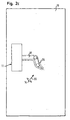
- FIG. 1 and 2 show an apparatus for controlling a safety-related function of a robot 11 designed as a robot with a movable robot arm 12.
- the machine 11 comprises a machine control 19, which is connected to an evaluation unit 17 via a line 15 for bidirectional transmission of data ,
- a wireless connection can also be provided.
- the evaluation unit 17 is connected via a further line 21 to a trained as a security camera sensor 16, in which case a wireless connection is also conceivable in principle.
- a security camera sensor 16 in which case a wireless connection is also conceivable in principle.
- the sensor can also be designed as another position and / or time-resolving sensor, for example as a laser scanner, in particular as a surface sensor.
- the sensor 16 is positioned above the machine 11 to monitor a surveillance area 10 (see FIG. 2) that includes the work area of the machine 11 within which the robotic arm 12 moves and an area adjacent thereto. Within the monitoring area 10 is a person 14 (object), which is detected by the sensor 16, wherein data on the position, movement direction and / or movement speed of the person 14 are transmitted via the line 21 to the evaluation unit 17.
- a danger zone 22 can be seen, which is determined by the evaluation unit 17.
- the danger zone 22 identifies the area of the surveillance area 10 whose violation by an object 14 must trigger a safety-relevant function. For example, when the person 14 enters the danger zone 22, the machine 11 can be switched off.
- the size and shape of the danger zone 22 are determined by the evaluation unit 17 based on the data obtained directly from the machine control 19 via the line 18, such as position, movement speed and direction of movement of the robot arm 12.
- the danger zone 22 as shown in FIGS. 1 and 2
- the data collected by the sensor 16 or derived therefrom with respect to the person 14, such as, for example, their position, movement speed and direction of movement, are also used to define the danger zone 22.
- the danger zone 22 can be determined dynamically, ie with the robot arm 12, or statically.
- second danger zone 24 is indicated by dashed lines in Fig. 1. According to FIG. 1, the person 14 would be arranged within the danger zone 24, so that the machine 11 would be switched off, for example, which is avoided with the minimized danger zone 22 according to the invention.
- velocities are in magnitude and direction, respectively.
- the velocity vectors of the robot arm 12 and the person 14 are represented by arrows 18 and 20.
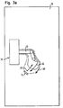
- FIGS. 2 a) to 2 c) show a further difference in the determination of the danger zone in the case of a direct coupling of the machine control 19 with the evaluation unit 17 in contrast to an indirect coupling via measurements of the sensor 16.
- Fig. 2a is due to the relative speed between person 14 and robot arm 12 defined danger zone according to the invention 22 just so large that no safety-related function is triggered, while in a danger zone 24 according to the prior art, a safety-relevant function would be triggered.
- Fig. 2b the relative speed between the person 14 and the robot arm 12 is greater than in Fig. 2a), which is illustrated by the greater length of the arrows 18 and 20.
- the hazard area 24 according to the invention is set larger according to the higher speed, so that even after the invention reliably a safety-relevant function is triggered.
- Fig. 2c shows the case that the robot arm 12 is stationary.
- a safety distance between person 14 and robot arm 12 still has to be maintained, since it can not be assumed that the robot arm 12 is at a further standstill or the danger zone 24 must be defined with a safety tolerance due to the measuring process of the sensor 16.
- the method according to the invention according to which the future position of the robot arm 12 of the evaluation unit 17 is known or can be reliably established before restarting the robot arm 12 of the danger zone 22 due to the direct coupling of the machine control 19 and evaluation 17, can at a longer idle phase of the robot arm 12, the person 14 to approach the robot arm 12, for example, perform maintenance.
- Fig. 3 illustrates the importance of determining the future movement of the machine.
- the person 14 and the robot arm 12 first move towards each other according to the arrows 18 and 20.
- the movement of the robot arm 12 slows down in the further course of time movement.
- the danger area 22 can be correspondingly reduced, so that the machine 11 does not have to be switched off.
- the machine 11 would have to be switched off since the size of the danger zone 24 is not reduced.
- Fig. 3b is indicated by an arrow 18 "that the robot arm 12 just starts to turn around while the person 14 continues to move to the robot arm 12. If the future position of the robot arm 12 and the future direction of motion is not evaluated, so again, the machine 11 would have to be switched off, as indicated by the prior art danger zone 24. According to the invention, however, the size of the danger zone 22 can be adapted to the future backward movement of the robot arm 12, again preventing unnecessary shutdown of the machine 11 ,
- the danger area 22 can be set to zero, so that the person 14 can approach the stationary robot arm 12 down to the zero distance. Due to the knowledge of the future planned movement of the robot arm 12, these movements are prevented from the outset, so that no sudden movement of the robot arm 12 can bring the person 14 in danger.
Landscapes
- Engineering & Computer Science (AREA)
- General Engineering & Computer Science (AREA)
- Mechanical Engineering (AREA)
- Manipulator (AREA)
- Control And Safety Of Cranes (AREA)
- Component Parts Of Construction Machinery (AREA)
- Control Of Positive-Displacement Air Blowers (AREA)
Claims (18)
- Dispositif de commande d'au moins une fonction concernant la sécurité d'une machine (11), comportant une commande de machine (19) pour commander les mouvements de la machine (11), comportant au moins un capteur (16) pour détecter un objet (14) à l'intérieur d'une zone de surveillance (10) et comportant une unité d'évaluation (17) pour déterminer une zone de danger (22) et pour déclencher la fonction concernant la sécurité lorsque l'objet (14) détecté pénètre dans la zone de danger (22), caractérisé en ce que pour déterminer la zone de danger (22), l'unité d'évaluation (17) est couplée à la commande de machine (19) et en ce que l'unité d'évaluation (17) est réalisée pour dériver les paramètres nécessaires pour la détermination de la zone de danger (22) à partir des signaux de commande utilisés par la commande de machine (19) pour commander les mouvements de la machine (11).
- Dispositif selon la revendication 1, caractérisé en ce que pour déterminer la zone de danger (22), l'unité d'évaluation (17) est couplée au capteur (16).
- Dispositif selon l'une des revendications précédentes, caractérisé en ce que le capteur (16) a une résolution locale et/ou temporelle et l'unité d'évaluation (17) est réalisée pour déterminer la position, la direction de mouvement et/ou la vitesse de mouvement de l'objet (14).
- Dispositif selon l'une des revendications précédentes, caractérisé en ce que la commande de machine (19) est réalisée pour transmettre la position momentanée et/ou la direction de mouvement momentanée et/ou la vitesse de mouvement momentanée de la machine (11) à l'unité d'évaluation (17).
- Dispositif selon l'une des revendications précédentes, caractérisé en ce que la commande de machine (19) est réalisée pour transmettre la position future, en particulier la position immédiatement future et/ou la direction de mouvement future, en particulier la direction de mouvement immédiatement future et/ou la vitesse de mouvement future, en particulier la vitesse de mouvement immédiatement future de la machine (11) à l'unité d'évaluation (17).
- Dispositif selon l'une des revendications précédentes, caractérisé en ce que l'extension de la zone de danger (22) à l'arrêt de la machine (11) est égale à zéro.
- Dispositif selon l'une des revendications précédentes, caractérisé en ce que
le ralentissement et/ou l'arrêt de la machine est défini en tant que fonction concernant la sécurité et/ou en ce que
le déport de la machine (11) par rapport à l'objet (14) est défini en tant que fonction concernant la sécurité et/ou en ce que
l'émission d'un signal d'alarme acoustique et/ou optique est définie en tant que fonction concernant la sécurité. - Dispositif selon l'une des revendications précédentes, caractérisé en ce que plusieurs objets (14) peuvent être surveillés par ledit au moins un capteur (16).
- Dispositif selon l'une des revendications précédentes, caractérisé en ce qu'il est fait une classification des objets (12, 14) détectés dans la zone de surveillance (10) en des objets (12) appartenant à la machine et en des objets (14) n'appartenant pas à la machine (11), et en ce que la fonction concernant la sécurité ne peut pas être déclenchée par la détection d'objets (12) appartenant à la machine (11).
- Procédé de commande d'au moins une fonction concernant la sécurité d'une machine (11) dont les mouvements sont commandés via une commande de machine (19), comportant au moins un capteur (16) pour détecter un objet (14) à l'intérieur d'une zone de surveillance (10) et comportant une unité d'évaluation (17) qui détermine une zone de danger (22) et déclenche la fonction concernant la sécurité lorsque l'objet (14) détecté pénètre dans la zone de danger (22), en particulier destiné à être utilisé dans un dispositif selon l'une des revendications précédentes, caractérisé en ce que
l'unité d'évaluation (17) est couplée à une commande de machine (19) pour déterminer la zone de danger (22) et en ce que l'unité d'évaluation (17) dérive les paramètres nécessaires à cet effet à partir des signaux de commande utilisés par la commande de machine (19) pour commander les mouvements de la machine (11). - Procédé selon la revendication 10, caractérisé en ce que l'unité d'évaluation (17) est couplée au capteur (16) pour déterminer la zone de danger (22).
- Procédé selon l'une des revendications précédentes, caractérisé en ce que l'objet (14) est détecté avec résolution locale et/ou temporelle par le capteur (16) et en ce que la position, la direction de mouvement et/ou la vitesse de mouvement de l'objet est déterminée par l'unité d'évaluation (17).
- Procédé selon l'une des revendications 10 à 12, caractérisé en ce que l'unité d'évaluation (17) traite les signaux de commande de la commande de machine (19) du point de vue de la position momentanée et/ou de la direction de mouvement momentanée et/ou de la vitesse de mouvement momentanée de la machine (11).
- Procédé selon l'une des revendications 10 à 13, caractérisé en ce que l'unité d'évaluation (17) traite les signaux de commande de la commande de machine (19) du point de vue de la position future, en particulier la position immédiatement future et/ou de la direction de mouvement future, en particulier de la direction de mouvement immédiatement future et/ou de la vitesse de mouvement future, en particulier de la vitesse de mouvement immédiatement future de la machine (11).
- Procédé selon l'une des revendications 10 à 14, caractérisé en ce que l'extension de la zone de danger (22) à l'arrêt de la machine (11) est égale à zéro.
- Procédé selon l'une des revendications 10 à 15, caractérisé en ce que
le déclenchement de la fonction concernant la sécurité comprend le ralentissement et/ou l'arrêt de la machine (11) et/ou en ce que
le déclenchement de la fonction concernant la sécurité comprend un déport de la machine (11) par rapport à l'objet (14) et/ou en ce que
le déclenchement de la fonction concernant la sécurité comprend l'émission d'un signal d'alarme acoustique et/ou optique. - Procédé selon l'une des revendications 10 à 16, caractérisé en ce que plusieurs objets (14) sont surveillés en même temps par ledit au moins un capteur (16).
- Procédé selon l'une des revendications 10 à 17, caractérisé en ce que les objets (12, 14) saisis par le capteur (16) sont classifiés en objets (12) appartenant à la machine et en objets (14) n'appartenant pas à la machine, de sorte qu'un objet (12) appartenant à la machine ne déclenche pas la fonction concernant la sécurité.
Applications Claiming Priority (1)
| Application Number | Priority Date | Filing Date | Title |
|---|---|---|---|
| DE102004043514A DE102004043514A1 (de) | 2004-09-08 | 2004-09-08 | Verfahren und Vorrichtung zum Steuern einer sicherheitsrelevanten Funktion einer Maschine |
Publications (3)
| Publication Number | Publication Date |
|---|---|
| EP1635107A1 EP1635107A1 (fr) | 2006-03-15 |
| EP1635107B1 true EP1635107B1 (fr) | 2007-02-14 |
| EP1635107B2 EP1635107B2 (fr) | 2016-01-27 |
Family
ID=34982417
Family Applications (1)
| Application Number | Title | Priority Date | Filing Date |
|---|---|---|---|
| EP05014464.1A Active EP1635107B2 (fr) | 2004-09-08 | 2005-07-04 | Procédé et dispositif de commande d'une fonction de sécurité d'une machine |
Country Status (5)
| Country | Link |
|---|---|
| US (1) | US7623031B2 (fr) |
| EP (1) | EP1635107B2 (fr) |
| AT (1) | ATE354056T1 (fr) |
| DE (2) | DE102004043514A1 (fr) |
| ES (1) | ES2278361T3 (fr) |
Cited By (3)
| Publication number | Priority date | Publication date | Assignee | Title |
|---|---|---|---|---|
| EP2386876A1 (fr) | 2010-05-04 | 2011-11-16 | Sick AG | Capteur de sécurité optoélectronique mesurant l'éloignement et procédé de surveillance d'une zone de surveillance |
| EP3578319A1 (fr) | 2018-06-07 | 2019-12-11 | Sick AG | Procédé de sécurisation d'un endroit dangereux |
| EP3611422A1 (fr) | 2018-08-15 | 2020-02-19 | Sick Ag | Dispositif capteur et procédé de sécurisation d'une zone de surveillance |
Families Citing this family (92)
| Publication number | Priority date | Publication date | Assignee | Title |
|---|---|---|---|---|
| FR2894318B1 (fr) * | 2005-12-07 | 2008-03-07 | Lectra Sa | Procede de gestion de securite active pour une machine de travail automatique. |
| US8676379B2 (en) * | 2006-07-04 | 2014-03-18 | Panasonic Corporation | Device and method for controlling robot arm, robot, and robot arm control program |
| DE102006046759B4 (de) * | 2006-09-29 | 2018-05-17 | Abb Ag | Verfahren zur Erhöhung der Sicherheit beim Betrieb eines Roboters |
| DE102007009225B3 (de) * | 2007-02-26 | 2008-07-03 | Sick Ag | Bearbeitungsmaschine |
| DE102007028390A1 (de) * | 2007-06-15 | 2008-12-18 | Abb Research Ltd. | Prozesssteuerung, System und Verfahren zur automatisierten Anpassung von Prozessparametern wenigstens einer Handhabungsvorrichtung |
| JP2009050958A (ja) * | 2007-08-27 | 2009-03-12 | Fanuc Ltd | 停止監視機能を備えたロボット制御装置 |
| DE102008021671B4 (de) * | 2008-04-30 | 2013-04-11 | Kuka Laboratories Gmbh | Verfahren und Vorrichtung zur Überwachung eines Manipulators |
| DE102008001664B4 (de) | 2008-05-08 | 2015-07-30 | Deutsches Zentrum für Luft- und Raumfahrt e.V. | Medizinischer Roboter und Verfahren zur Erfüllung der Performanceanforderung eines medizinischen Roboters |
| DE102009051145A1 (de) * | 2008-10-29 | 2010-05-06 | Sms Siemag Aktiengesellschaft | Roboterisierte hüttenmännische Anlage |
| CA2741710C (fr) | 2008-10-29 | 2014-06-03 | Sms Siemag Aktiengesellschaft | Systeme interactif de robot |
| US8249747B2 (en) | 2008-12-03 | 2012-08-21 | Abb Research Ltd | Robot safety system and a method |
| DE102008063081B4 (de) * | 2008-12-24 | 2014-10-23 | Gottfried Wilhelm Leibniz Universität Hannover | Sicherungsvorrichtung und Verfahren zum Betreiben einer mehrgliedrigen Maschine |
| JP4648486B2 (ja) | 2009-01-26 | 2011-03-09 | ファナック株式会社 | 人間とロボットとの協調動作領域を有する生産システム |
| WO2010088934A1 (fr) | 2009-02-04 | 2010-08-12 | Sms Siemag Ag | Robots dotés d'une zone de protection variable |
| EP2315052B1 (fr) * | 2009-10-22 | 2012-02-29 | Sick Ag | Scanner de sécurité |
| WO2011089885A1 (fr) * | 2010-01-25 | 2011-07-28 | パナソニック株式会社 | Dispositif de présentation de danger, système de présentation de danger, procédé de présentation de danger et programme associé |
| DE102010017857B4 (de) | 2010-04-22 | 2019-08-08 | Sick Ag | 3D-Sicherheitsvorrichtung und Verfahren zur Absicherung und Bedienung mindestens einer Maschine |
| US20110298579A1 (en) * | 2010-06-08 | 2011-12-08 | Cedes Safety & Automation Ag | Dynamically adaptable safety zones |
| US20120081537A1 (en) * | 2010-10-04 | 2012-04-05 | General Electric Company | Camera protective system and method |
| US20120095575A1 (en) * | 2010-10-14 | 2012-04-19 | Cedes Safety & Automation Ag | Time of flight (tof) human machine interface (hmi) |
| DE102010063214A1 (de) * | 2010-12-16 | 2012-06-21 | Robert Bosch Gmbh | Sicherungseinrichtung für eine Handhabungsvorrichtung, insbesondere einen Industrieroboter, sowie Verfahren zum Betreiben der Sicherungseinrichtung |
| DE102011009299A1 (de) | 2011-01-24 | 2012-07-26 | Esab Cutting Systems Gmbh | Werkstückbearbeitungsmaschine und Verfahren zum Betreiben einer solchen |
| WO2012174406A1 (fr) | 2011-06-15 | 2012-12-20 | University Of Washington | Procédés et systèmes de rendu haptique et de création de dispositifs virtuels à partir de nuages de points |
| ITBO20110626A1 (it) * | 2011-11-04 | 2013-05-05 | Biesse Spa | Macchina per la lavorazione di componenti di legno o simili |
| WO2013105264A1 (fr) * | 2012-01-13 | 2013-07-18 | 三菱電機株式会社 | Système de mesure de risque |
| DE102012007242A1 (de) * | 2012-03-09 | 2013-09-12 | Fraunhofer-Gesellschaft zur Förderung der angewandten Forschung e.V. | Vorrichtung und Verfahren zur sicheren Mensch-Roboter-Kooperation |
| DE102012102236A1 (de) | 2012-03-16 | 2013-09-19 | Pilz Gmbh & Co. Kg | Verfahren und Vorrichtung zum Absichern eines gefährlichen Arbeitsbereichs einer automatisiert arbeitenden Maschine |
| CN104321169A (zh) * | 2012-05-21 | 2015-01-28 | 株式会社安川电机 | 机器人及机器人系统 |
| ITRN20120036A1 (it) | 2012-07-09 | 2014-01-10 | Wide Automation S R L | Sistema e procedimento di supervisione |
| CN103894807A (zh) * | 2012-12-28 | 2014-07-02 | Abb技术有限公司 | 降低操作员潜在伤害的方法和装置 |
| JP6123307B2 (ja) | 2013-01-23 | 2017-05-10 | 株式会社デンソーウェーブ | ロボット周辺への物体の侵入を監視する監視システムおよび監視方法 |
| US20140320629A1 (en) | 2013-01-24 | 2014-10-30 | University Of Washington Through Its Center For Commericialization | Haptically-Enabled Co-Robotics for Underwater Tasks |
| JP5668770B2 (ja) * | 2013-03-15 | 2015-02-12 | 株式会社安川電機 | ロボットシステム、及び、ロボットシステムの制御方法 |
| JP5835254B2 (ja) * | 2013-03-15 | 2015-12-24 | 株式会社安川電機 | ロボットシステム、及び、ロボットシステムの制御方法 |
| JP5672327B2 (ja) * | 2013-03-19 | 2015-02-18 | 株式会社安川電機 | ロボットシステム |
| DE102013104265A1 (de) | 2013-04-26 | 2014-10-30 | Pilz Gmbh & Co. Kg | Vorrichtung und Verfahren zum Absichern einer automatisiert arbeitenden Maschine |
| US9427871B2 (en) * | 2013-05-06 | 2016-08-30 | Abb Technology Ag | Human safety provision in mobile automation environments |
| DE202013104264U1 (de) * | 2013-09-18 | 2015-01-09 | Daimler Ag | Arbeitsstation |
| DE202013104860U1 (de) * | 2013-10-30 | 2015-02-02 | Daimler Ag | Arbeitsvorrichtung |
| TWI547355B (zh) * | 2013-11-11 | 2016-09-01 | 財團法人工業技術研究院 | 人機共生安全監控系統及其方法 |
| US9604362B2 (en) * | 2013-11-27 | 2017-03-28 | Infineon Technologies Ag | Method and apparatus for failure handling of a robot |
| DE102013114773A1 (de) * | 2013-12-23 | 2015-06-25 | Deutsches Zentrum für Luft- und Raumfahrt e.V. | Einrichtung zur Übertragung von Energie mittels Laserstrahlung |
| US9452531B2 (en) * | 2014-02-04 | 2016-09-27 | Microsoft Technology Licensing, Llc | Controlling a robot in the presence of a moving object |
| US10226869B2 (en) | 2014-03-03 | 2019-03-12 | University Of Washington | Haptic virtual fixture tools |
| JP6402469B2 (ja) * | 2014-04-04 | 2018-10-10 | 富士電機株式会社 | 安全制御装置および安全制御システム |
| DE102014209525A1 (de) * | 2014-05-20 | 2015-11-26 | Bayerische Motoren Werke Aktiengesellschaft | Verfahren zur Kommunikation zwischen einem Roboter und einem Menschen bei der Mensch-Roboter-Kooperation |
| DE102014210612A1 (de) * | 2014-06-04 | 2015-12-17 | Holzma Plattenaufteiltechnik Gmbh | Verfahren zum Betreiben einerPlattenbearbeitungsanlage, sowiePlattenbearbeitungsanlage |
| EP2952301B1 (fr) * | 2014-06-05 | 2019-12-25 | Softbank Robotics Europe | Robot humanoïde avec des capacités d'évitement de collisions et de récupération d'une trajectoire |
| US9902061B1 (en) * | 2014-08-25 | 2018-02-27 | X Development Llc | Robot to human feedback |
| DE102014226691A1 (de) | 2014-12-19 | 2016-06-23 | Carl Zeiss Industrielle Messtechnik Gmbh | Verfahren zur Überwachung eines Koordinatenmessgeräts |
| US9914218B2 (en) * | 2015-01-30 | 2018-03-13 | Toyota Motor Engineering & Manufacturing North America, Inc. | Methods and apparatuses for responding to a detected event by a robot |
| DE102015007395A1 (de) * | 2015-06-08 | 2016-12-08 | Kuka Roboter Gmbh | Verfahren und System zum Betreiben und/oder Überwachen einer Maschine, insbesondere eines Roboters |
| US10198706B2 (en) * | 2015-07-31 | 2019-02-05 | Locus Robotics Corp. | Operator identification and performance tracking |
| DE102015011910A1 (de) * | 2015-09-11 | 2017-03-16 | Kuka Roboter Gmbh | Verfahren und System zum Steuern einer Roboteranordnung |
| US10065316B2 (en) * | 2016-02-05 | 2018-09-04 | Rethink Robotics, Inc. | Systems and methods for safe robot operation |
| US10924881B2 (en) * | 2016-03-03 | 2021-02-16 | Husqvarna Ab | Device for determining construction device and worker position |
| JP6733239B2 (ja) * | 2016-03-18 | 2020-07-29 | セイコーエプソン株式会社 | 制御装置及びロボットシステム |
| US11052537B2 (en) * | 2016-05-16 | 2021-07-06 | Mitsubishi Electric Corporation | Robot operation evaluation device, robot operation evaluating method, and robot system |
| ITUA20163608A1 (it) * | 2016-05-19 | 2017-11-19 | Milano Politecnico | Procedimento e dispositivo per il controllo della movimentazione di uno o più robot collaborativi |
| DE102016007519A1 (de) * | 2016-06-20 | 2017-12-21 | Kuka Roboter Gmbh | Überwachung einer Anlage mit wenigstens einem Roboter |
| US9868214B2 (en) | 2016-06-20 | 2018-01-16 | X Development Llc | Localization of a mobile system |
| US10016896B2 (en) * | 2016-06-30 | 2018-07-10 | Brain Corporation | Systems and methods for robotic behavior around moving bodies |
| CN107717982B (zh) * | 2016-08-12 | 2020-09-25 | 财团法人工业技术研究院 | 机械手臂的控制装置及操作方法 |
| US11000953B2 (en) * | 2016-08-17 | 2021-05-11 | Locus Robotics Corp. | Robot gamification for improvement of operator performance |
| JP6822069B2 (ja) * | 2016-11-01 | 2021-01-27 | オムロン株式会社 | 監視システム、監視装置、および監視方法 |
| US10416646B2 (en) | 2016-11-11 | 2019-09-17 | Safe Tek, LLC | Systems, methods, and articles of manufacture for operation of an industrial machine |
| DE102016222245A1 (de) * | 2016-11-14 | 2018-05-30 | Volkswagen Aktiengesellschaft | Einrichtung und Verfahren zur Einwirkung auf Gegenstände |
| JP6490121B2 (ja) * | 2017-02-17 | 2019-03-27 | ファナック株式会社 | ロボットシステム |
| JP6496335B2 (ja) * | 2017-03-03 | 2019-04-03 | ファナック株式会社 | ロボットシステム |
| US10766140B2 (en) * | 2017-04-13 | 2020-09-08 | Battelle Memorial Institute | Teach mode collision avoidance system and method for industrial robotic manipulators |
| JP2018176397A (ja) * | 2017-04-21 | 2018-11-15 | オムロン株式会社 | ロボットシステム |
| DE102017111886B3 (de) * | 2017-05-31 | 2018-05-03 | Sick Ag | Bestimmen der Bewegung einer abzusichernden Maschine |
| DE102017111885B4 (de) | 2017-05-31 | 2019-06-27 | Sick Ag | Verfahren und System zum Überwachen einer Maschine |
| DE102017005604A1 (de) * | 2017-06-12 | 2018-12-13 | Kuka Deutschland Gmbh | Überwachung eines Roboters |
| EP3427904B1 (fr) * | 2017-07-13 | 2020-06-10 | Siemens Aktiengesellschaft | Système comprenant un manipulateur et un dispositif de limitation d'un espace de travail |
| DE202017104603U1 (de) | 2017-08-01 | 2018-11-06 | Sick Ag | System zum Absichern einer Maschine |
| JP2019058990A (ja) * | 2017-09-27 | 2019-04-18 | ファナック株式会社 | ロボットシステム |
| DE102017221305A1 (de) * | 2017-11-23 | 2019-05-23 | Robert Bosch Gmbh | Verfahren zum Betreiben eines kollaborativen Roboters |
| DE102018110852A1 (de) * | 2018-05-07 | 2019-11-07 | Kinotex Sensor Gmbh | Vorrichtung und Verfahren zur Sicherung eines maschinell oder automatisch gesteuerten beweglichen Gerätes und Sensorkachel |
| JP7155660B2 (ja) * | 2018-06-26 | 2022-10-19 | セイコーエプソン株式会社 | ロボット制御装置およびロボットシステム |
| DE102018118265B4 (de) * | 2018-07-27 | 2020-11-12 | Sick Ag | Verfahren und Überwachungssystem zum Absichern einer Maschine |
| JP7224843B2 (ja) * | 2018-10-15 | 2023-02-20 | 株式会社今仙電機製作所 | ロボット、このロボットを備えた搬送車、このロボットの制御方法及び制御プログラム |
| EP3650740B1 (fr) | 2018-11-06 | 2020-12-30 | Sick Ag | Système de sécurité et procédé de surveillance d'une machine |
| CN109732220B (zh) * | 2018-12-14 | 2021-02-05 | 青岛宇鑫源金属制品有限公司 | 一种激光切割机 |
| DE102018133472B3 (de) * | 2018-12-21 | 2020-03-12 | Franka Emika Gmbh | Bewegungsüberwachung eines Robotermanipulators |
| EP3744482B1 (fr) | 2019-05-27 | 2021-12-29 | Sick Ag | Fixation d'une pièce de machine mobile |
| US10872514B1 (en) | 2019-08-14 | 2020-12-22 | The Boeing Company | Safety system for tracking movable objects during vehicle production |
| EP3825731B1 (fr) | 2019-11-21 | 2022-01-05 | Sick Ag | Capteur optoélectronique de sécurité et procédé de détermination sécurisée de position propre |
| EP3859382B1 (fr) * | 2020-01-28 | 2022-08-03 | Sick Ag | Système de sécurité et procédé de localisation d'une personne ou d'un objet dans une zone de surveillance à l'aide d'un système de sécurité |
| EP4047257A1 (fr) * | 2021-02-22 | 2022-08-24 | Leuze electronic GmbH + Co. KG | Dispositif de surveillance et procédé de fonctionnement d'un dispositif de surveillance |
| KR20240070752A (ko) * | 2022-11-14 | 2024-05-22 | (주)아이티공간 | 가상펜스와 스켈레톤 영상을 이용한 기기의 안전사고 방지 시스템 |
| KR20240074933A (ko) * | 2022-11-14 | 2024-05-29 | (주)아이티공간 | 가상펜스와 스켈레톤 영상을 이용한 기기의 안전사고 방지 시스템 |
Citations (6)
| Publication number | Priority date | Publication date | Assignee | Title |
|---|---|---|---|---|
| JPH08108383A (ja) | 1994-10-05 | 1996-04-30 | Fujitsu Ltd | マニピュレータ制御装置 |
| EP1267234A2 (fr) | 1997-12-06 | 2002-12-18 | Elan Schaltelemente GmbH & Co. KG | Méthode de surveillance d'un équipement technique, en particulier un manipulateur, ainsi qu'un appareil de surveillance et de commande |
| US20030024421A1 (en) | 2001-08-03 | 2003-02-06 | Sick Ag | Method of controlling a light grid |
| DE10152543A1 (de) | 2001-10-24 | 2003-05-08 | Sick Ag | Verfahren und Vorrichtung zum Steuern einer sicherheitsrelevanten Funktion einer Maschine |
| DE10245720A1 (de) | 2002-09-24 | 2004-04-01 | Pilz Gmbh & Co. | Verfahren un Vorrichtung zum Absichern eines Gefahrenbereichs |
| WO2004042269A1 (fr) | 2002-11-05 | 2004-05-21 | Pilz Gmbh & Co. | Dispositif de securite pour machine, en particulier pour une presse a plier |
Family Cites Families (4)
| Publication number | Priority date | Publication date | Assignee | Title |
|---|---|---|---|---|
| ITRE20020030A1 (it) * | 2002-04-12 | 2003-10-13 | Giorgio Grasselli | Sistema di sicurezza perfezionato per macchine utensili |
| US7448241B2 (en) * | 2002-06-11 | 2008-11-11 | Davies Kevin S | Safety system |
| WO2004009303A1 (fr) * | 2002-07-18 | 2004-01-29 | Kabushiki Kaisha Yaskawa Denki | Commande de robot et systeme robot |
| DE10360789B4 (de) * | 2003-12-23 | 2007-03-15 | Leuze Lumiflex Gmbh + Co. Kg | Vorrichtung zur Überwachung eines Erfassungsbereichs an einem Arbeitsmittel |
-
2004
- 2004-09-08 DE DE102004043514A patent/DE102004043514A1/de not_active Withdrawn
-
2005
- 2005-07-04 AT AT05014464T patent/ATE354056T1/de not_active IP Right Cessation
- 2005-07-04 DE DE502005000379T patent/DE502005000379D1/de active Active
- 2005-07-04 EP EP05014464.1A patent/EP1635107B2/fr active Active
- 2005-07-04 ES ES05014464T patent/ES2278361T3/es active Active
- 2005-08-25 US US11/212,935 patent/US7623031B2/en active Active
Patent Citations (6)
| Publication number | Priority date | Publication date | Assignee | Title |
|---|---|---|---|---|
| JPH08108383A (ja) | 1994-10-05 | 1996-04-30 | Fujitsu Ltd | マニピュレータ制御装置 |
| EP1267234A2 (fr) | 1997-12-06 | 2002-12-18 | Elan Schaltelemente GmbH & Co. KG | Méthode de surveillance d'un équipement technique, en particulier un manipulateur, ainsi qu'un appareil de surveillance et de commande |
| US20030024421A1 (en) | 2001-08-03 | 2003-02-06 | Sick Ag | Method of controlling a light grid |
| DE10152543A1 (de) | 2001-10-24 | 2003-05-08 | Sick Ag | Verfahren und Vorrichtung zum Steuern einer sicherheitsrelevanten Funktion einer Maschine |
| DE10245720A1 (de) | 2002-09-24 | 2004-04-01 | Pilz Gmbh & Co. | Verfahren un Vorrichtung zum Absichern eines Gefahrenbereichs |
| WO2004042269A1 (fr) | 2002-11-05 | 2004-05-21 | Pilz Gmbh & Co. | Dispositif de securite pour machine, en particulier pour une presse a plier |
Non-Patent Citations (2)
| Title |
|---|
| STEFAN THIEMERMANN: "Direkte Mensch-Roboter-Kooperation in der Kleinteilemontage mit einem SCARA-Roboter", 2005, JOST-JETTER VERLAG,, pages: 22, 23, XP002523808 |
| THIEMERMANN ET AL.: "Trennung aufgehoben", ELEKTRONIKNET.DE, 30 April 2003 (2003-04-30), XP055257919, Retrieved from the Internet <URL:http://www.elektroniknet.de/topics/automatisieren/2002/0026/index.htm> |
Cited By (6)
| Publication number | Priority date | Publication date | Assignee | Title |
|---|---|---|---|---|
| EP2386876A1 (fr) | 2010-05-04 | 2011-11-16 | Sick AG | Capteur de sécurité optoélectronique mesurant l'éloignement et procédé de surveillance d'une zone de surveillance |
| EP3578319A1 (fr) | 2018-06-07 | 2019-12-11 | Sick AG | Procédé de sécurisation d'un endroit dangereux |
| DE102019111640A1 (de) | 2018-06-07 | 2019-12-12 | Sick Ag | Verfahren zum Absichern einer Gefahrenstelle |
| US10726538B2 (en) | 2018-06-07 | 2020-07-28 | Sick Ag | Method of securing a hazard zone |
| EP3611422A1 (fr) | 2018-08-15 | 2020-02-19 | Sick Ag | Dispositif capteur et procédé de sécurisation d'une zone de surveillance |
| US11174989B2 (en) | 2018-08-15 | 2021-11-16 | Sick Ag | Sensor arrangement and method of securing a monitored zone |
Also Published As
| Publication number | Publication date |
|---|---|
| US7623031B2 (en) | 2009-11-24 |
| EP1635107A1 (fr) | 2006-03-15 |
| ATE354056T1 (de) | 2007-03-15 |
| EP1635107B2 (fr) | 2016-01-27 |
| ES2278361T3 (es) | 2007-08-01 |
| DE102004043514A1 (de) | 2006-03-09 |
| DE502005000379D1 (de) | 2007-03-29 |
| US20060049939A1 (en) | 2006-03-09 |
Similar Documents
| Publication | Publication Date | Title |
|---|---|---|
| EP1635107B1 (fr) | Procédé et dispositif de commande d'une fonction de sécurité d'une machine | |
| EP2989369B1 (fr) | Dispositif et procédé de sécurisation d'une machine travaillant de manière automatisée | |
| EP2985636B1 (fr) | Procédé d'alignement d'un dispositif de capteurs | |
| EP1200767B1 (fr) | Dispositif de protection pour machines telles que presses-plieuses, decoupeuses, machines a estamper ou analogues | |
| EP1353196B1 (fr) | Détection d'un objet et barrière optique | |
| EP1306603B1 (fr) | Procédé et dispositif de commande d'une fonction relative à la sécurité d'une machine | |
| EP1494048B1 (fr) | Rideau de lumière | |
| EP2234778B1 (fr) | Ensemble machine-outil et procédé avec ce ensemble machine-outil | |
| DE102007033766B4 (de) | Lichtgitter | |
| EP1443343B1 (fr) | Détecteur optique avec plusiers sorties de commutation | |
| EP3916286B1 (fr) | Capteur optoélectronique de sécurité et procédé de sécurisation d'une machine | |
| EP3425256A1 (fr) | Système de protection d'accès | |
| EP3150898B2 (fr) | Procede de commande automatisee d'un composant de machine | |
| DE102019104218A1 (de) | Arbeitszug, umfassend eine Bodenbearbeitungsmaschine und ein weiteres Fahrzeug sowie eine automatisierte Abstandsüberwachung | |
| DE102019131774A1 (de) | Überwachungssystem für Roboter und Robotersystem | |
| EP3287809B1 (fr) | Procédé de fonctionnement d'un dispositif de baleyage et dispositif de baleyage | |
| DE102017101905B4 (de) | Überwachungseinrichtung | |
| EP2395372B1 (fr) | Scanner de sécurité | |
| EP2811318B1 (fr) | Capteur optoélectronique | |
| EP3882505B1 (fr) | Dispositif de surveillance et procédé de fonctionnement d'un dispositif de surveillance | |
| EP2586544A1 (fr) | Machine-outil avec un dispositif de butée et procédé de fonctionnement de la machine-outil | |
| EP3447540B1 (fr) | Rideau lumineux | |
| EP2431650A1 (fr) | Système de protection pour unité de commande sur des machines, notamment des presses de pliage | |
| DE202010017960U1 (de) | Schutzsystem für Bediensicherheit an Maschinen, insbesondere Gesenkbiegepressen | |
| DE202008003444U1 (de) | Sicherheitseinrichtung zum Absichern einer Maschine |
Legal Events
| Date | Code | Title | Description |
|---|---|---|---|
| PUAI | Public reference made under article 153(3) epc to a published international application that has entered the european phase |
Free format text: ORIGINAL CODE: 0009012 |
|
| AK | Designated contracting states |
Kind code of ref document: A1 Designated state(s): AT BE BG CH CY CZ DE DK EE ES FI FR GB GR HU IE IS IT LI LT LU LV MC NL PL PT RO SE SI SK TR |
|
| AX | Request for extension of the european patent |
Extension state: AL BA HR MK YU |
|
| 17P | Request for examination filed |
Effective date: 20060613 |
|
| GRAP | Despatch of communication of intention to grant a patent |
Free format text: ORIGINAL CODE: EPIDOSNIGR1 |
|
| AKX | Designation fees paid |
Designated state(s): AT BE BG CH CY CZ DE DK EE ES FI FR GB GR HU IE IS IT LI LT LU LV MC NL PL PT RO SE SI SK TR |
|
| GRAS | Grant fee paid |
Free format text: ORIGINAL CODE: EPIDOSNIGR3 |
|
| GRAA | (expected) grant |
Free format text: ORIGINAL CODE: 0009210 |
|
| AK | Designated contracting states |
Kind code of ref document: B1 Designated state(s): AT BE BG CH CY CZ DE DK EE ES FI FR GB GR HU IE IS IT LI LT LU LV MC NL PL PT RO SE SI SK TR |
|
| PG25 | Lapsed in a contracting state [announced via postgrant information from national office to epo] |
Ref country code: SI Free format text: LAPSE BECAUSE OF FAILURE TO SUBMIT A TRANSLATION OF THE DESCRIPTION OR TO PAY THE FEE WITHIN THE PRESCRIBED TIME-LIMIT Effective date: 20070214 Ref country code: NL Free format text: LAPSE BECAUSE OF FAILURE TO SUBMIT A TRANSLATION OF THE DESCRIPTION OR TO PAY THE FEE WITHIN THE PRESCRIBED TIME-LIMIT Effective date: 20070214 Ref country code: FI Free format text: LAPSE BECAUSE OF FAILURE TO SUBMIT A TRANSLATION OF THE DESCRIPTION OR TO PAY THE FEE WITHIN THE PRESCRIBED TIME-LIMIT Effective date: 20070214 Ref country code: DK Free format text: LAPSE BECAUSE OF FAILURE TO SUBMIT A TRANSLATION OF THE DESCRIPTION OR TO PAY THE FEE WITHIN THE PRESCRIBED TIME-LIMIT Effective date: 20070214 Ref country code: IE Free format text: LAPSE BECAUSE OF FAILURE TO SUBMIT A TRANSLATION OF THE DESCRIPTION OR TO PAY THE FEE WITHIN THE PRESCRIBED TIME-LIMIT Effective date: 20070214 Ref country code: PL Free format text: LAPSE BECAUSE OF FAILURE TO SUBMIT A TRANSLATION OF THE DESCRIPTION OR TO PAY THE FEE WITHIN THE PRESCRIBED TIME-LIMIT Effective date: 20070214 |
|
| RAP1 | Party data changed (applicant data changed or rights of an application transferred) |
Owner name: SICK AG |
|
| REG | Reference to a national code |
Ref country code: GB Ref legal event code: FG4D Free format text: NOT ENGLISH |
|
| REG | Reference to a national code |
Ref country code: CH Ref legal event code: EP |
|
| REF | Corresponds to: |
Ref document number: 502005000379 Country of ref document: DE Date of ref document: 20070329 Kind code of ref document: P |
|
| REG | Reference to a national code |
Ref country code: IE Ref legal event code: FG4D Free format text: LANGUAGE OF EP DOCUMENT: GERMAN |
|
| GBT | Gb: translation of ep patent filed (gb section 77(6)(a)/1977) |
Effective date: 20070321 |
|
| REG | Reference to a national code |
Ref country code: SE Ref legal event code: TRGR |
|
| PG25 | Lapsed in a contracting state [announced via postgrant information from national office to epo] |
Ref country code: BG Free format text: LAPSE BECAUSE OF FAILURE TO SUBMIT A TRANSLATION OF THE DESCRIPTION OR TO PAY THE FEE WITHIN THE PRESCRIBED TIME-LIMIT Effective date: 20070514 |
|
| PG25 | Lapsed in a contracting state [announced via postgrant information from national office to epo] |
Ref country code: IS Free format text: LAPSE BECAUSE OF FAILURE TO SUBMIT A TRANSLATION OF THE DESCRIPTION OR TO PAY THE FEE WITHIN THE PRESCRIBED TIME-LIMIT Effective date: 20070614 |
|
| PG25 | Lapsed in a contracting state [announced via postgrant information from national office to epo] |
Ref country code: PT Free format text: LAPSE BECAUSE OF FAILURE TO SUBMIT A TRANSLATION OF THE DESCRIPTION OR TO PAY THE FEE WITHIN THE PRESCRIBED TIME-LIMIT Effective date: 20070716 |
|
| NLV1 | Nl: lapsed or annulled due to failure to fulfill the requirements of art. 29p and 29m of the patents act | ||
| REG | Reference to a national code |
Ref country code: ES Ref legal event code: FG2A Ref document number: 2278361 Country of ref document: ES Kind code of ref document: T3 |
|
| ET | Fr: translation filed | ||
| REG | Reference to a national code |
Ref country code: IE Ref legal event code: FD4D |
|
| PLBI | Opposition filed |
Free format text: ORIGINAL CODE: 0009260 |
|
| PG25 | Lapsed in a contracting state [announced via postgrant information from national office to epo] |
Ref country code: SK Free format text: LAPSE BECAUSE OF FAILURE TO SUBMIT A TRANSLATION OF THE DESCRIPTION OR TO PAY THE FEE WITHIN THE PRESCRIBED TIME-LIMIT Effective date: 20070214 |
|
| 26 | Opposition filed |
Opponent name: I F M ELECTRONIC GMBH Effective date: 20071114 |
|
| PG25 | Lapsed in a contracting state [announced via postgrant information from national office to epo] |
Ref country code: RO Free format text: LAPSE BECAUSE OF FAILURE TO SUBMIT A TRANSLATION OF THE DESCRIPTION OR TO PAY THE FEE WITHIN THE PRESCRIBED TIME-LIMIT Effective date: 20070214 Ref country code: CZ Free format text: LAPSE BECAUSE OF FAILURE TO SUBMIT A TRANSLATION OF THE DESCRIPTION OR TO PAY THE FEE WITHIN THE PRESCRIBED TIME-LIMIT Effective date: 20070214 |
|
| BERE | Be: lapsed |
Owner name: SICK A.G. Effective date: 20070731 |
|
| PG25 | Lapsed in a contracting state [announced via postgrant information from national office to epo] |
Ref country code: LV Free format text: LAPSE BECAUSE OF FAILURE TO SUBMIT A TRANSLATION OF THE DESCRIPTION OR TO PAY THE FEE WITHIN THE PRESCRIBED TIME-LIMIT Effective date: 20070214 |
|
| PLAX | Notice of opposition and request to file observation + time limit sent |
Free format text: ORIGINAL CODE: EPIDOSNOBS2 |
|
| PG25 | Lapsed in a contracting state [announced via postgrant information from national office to epo] |
Ref country code: LT Free format text: LAPSE BECAUSE OF FAILURE TO SUBMIT A TRANSLATION OF THE DESCRIPTION OR TO PAY THE FEE WITHIN THE PRESCRIBED TIME-LIMIT Effective date: 20070214 |
|
| PG25 | Lapsed in a contracting state [announced via postgrant information from national office to epo] |
Ref country code: MC Free format text: LAPSE BECAUSE OF NON-PAYMENT OF DUE FEES Effective date: 20070731 Ref country code: GR Free format text: LAPSE BECAUSE OF FAILURE TO SUBMIT A TRANSLATION OF THE DESCRIPTION OR TO PAY THE FEE WITHIN THE PRESCRIBED TIME-LIMIT Effective date: 20070515 |
|
| PLBB | Reply of patent proprietor to notice(s) of opposition received |
Free format text: ORIGINAL CODE: EPIDOSNOBS3 |
|
| PG25 | Lapsed in a contracting state [announced via postgrant information from national office to epo] |
Ref country code: BE Free format text: LAPSE BECAUSE OF NON-PAYMENT OF DUE FEES Effective date: 20070731 |
|
| PG25 | Lapsed in a contracting state [announced via postgrant information from national office to epo] |
Ref country code: AT Free format text: LAPSE BECAUSE OF NON-PAYMENT OF DUE FEES Effective date: 20070704 |
|
| PG25 | Lapsed in a contracting state [announced via postgrant information from national office to epo] |
Ref country code: EE Free format text: LAPSE BECAUSE OF FAILURE TO SUBMIT A TRANSLATION OF THE DESCRIPTION OR TO PAY THE FEE WITHIN THE PRESCRIBED TIME-LIMIT Effective date: 20070214 |
|
| PG25 | Lapsed in a contracting state [announced via postgrant information from national office to epo] |
Ref country code: CY Free format text: LAPSE BECAUSE OF FAILURE TO SUBMIT A TRANSLATION OF THE DESCRIPTION OR TO PAY THE FEE WITHIN THE PRESCRIBED TIME-LIMIT Effective date: 20070214 |
|
| PG25 | Lapsed in a contracting state [announced via postgrant information from national office to epo] |
Ref country code: LU Free format text: LAPSE BECAUSE OF NON-PAYMENT OF DUE FEES Effective date: 20070704 |
|
| PG25 | Lapsed in a contracting state [announced via postgrant information from national office to epo] |
Ref country code: HU Free format text: LAPSE BECAUSE OF FAILURE TO SUBMIT A TRANSLATION OF THE DESCRIPTION OR TO PAY THE FEE WITHIN THE PRESCRIBED TIME-LIMIT Effective date: 20070815 Ref country code: TR Free format text: LAPSE BECAUSE OF FAILURE TO SUBMIT A TRANSLATION OF THE DESCRIPTION OR TO PAY THE FEE WITHIN THE PRESCRIBED TIME-LIMIT Effective date: 20070214 |
|
| REG | Reference to a national code |
Ref country code: CH Ref legal event code: PL |
|
| PG25 | Lapsed in a contracting state [announced via postgrant information from national office to epo] |
Ref country code: LI Free format text: LAPSE BECAUSE OF NON-PAYMENT OF DUE FEES Effective date: 20090731 Ref country code: CH Free format text: LAPSE BECAUSE OF NON-PAYMENT OF DUE FEES Effective date: 20090731 |
|
| APBM | Appeal reference recorded |
Free format text: ORIGINAL CODE: EPIDOSNREFNO |
|
| APBP | Date of receipt of notice of appeal recorded |
Free format text: ORIGINAL CODE: EPIDOSNNOA2O |
|
| APAH | Appeal reference modified |
Free format text: ORIGINAL CODE: EPIDOSCREFNO |
|
| APBM | Appeal reference recorded |
Free format text: ORIGINAL CODE: EPIDOSNREFNO |
|
| APBP | Date of receipt of notice of appeal recorded |
Free format text: ORIGINAL CODE: EPIDOSNNOA2O |
|
| APBQ | Date of receipt of statement of grounds of appeal recorded |
Free format text: ORIGINAL CODE: EPIDOSNNOA3O |
|
| APBQ | Date of receipt of statement of grounds of appeal recorded |
Free format text: ORIGINAL CODE: EPIDOSNNOA3O |
|
| PGFP | Annual fee paid to national office [announced via postgrant information from national office to epo] |
Ref country code: ES Payment date: 20130722 Year of fee payment: 9 |
|
| PGFP | Annual fee paid to national office [announced via postgrant information from national office to epo] |
Ref country code: FR Payment date: 20130719 Year of fee payment: 9 Ref country code: GB Payment date: 20130723 Year of fee payment: 9 |
|
| PGFP | Annual fee paid to national office [announced via postgrant information from national office to epo] |
Ref country code: IT Payment date: 20130725 Year of fee payment: 9 |
|
| GBPC | Gb: european patent ceased through non-payment of renewal fee |
Effective date: 20140704 |
|
| REG | Reference to a national code |
Ref country code: FR Ref legal event code: ST Effective date: 20150331 |
|
| PG25 | Lapsed in a contracting state [announced via postgrant information from national office to epo] |
Ref country code: IT Free format text: LAPSE BECAUSE OF NON-PAYMENT OF DUE FEES Effective date: 20140704 |
|
| PG25 | Lapsed in a contracting state [announced via postgrant information from national office to epo] |
Ref country code: FR Free format text: LAPSE BECAUSE OF NON-PAYMENT OF DUE FEES Effective date: 20140731 Ref country code: GB Free format text: LAPSE BECAUSE OF NON-PAYMENT OF DUE FEES Effective date: 20140704 |
|
| APBU | Appeal procedure closed |
Free format text: ORIGINAL CODE: EPIDOSNNOA9O |
|
| REG | Reference to a national code |
Ref country code: ES Ref legal event code: FD2A Effective date: 20150828 |
|
| PG25 | Lapsed in a contracting state [announced via postgrant information from national office to epo] |
Ref country code: ES Free format text: LAPSE BECAUSE OF NON-PAYMENT OF DUE FEES Effective date: 20140705 |
|
| PUAH | Patent maintained in amended form |
Free format text: ORIGINAL CODE: 0009272 |
|
| STAA | Information on the status of an ep patent application or granted ep patent |
Free format text: STATUS: PATENT MAINTAINED AS AMENDED |
|
| 27A | Patent maintained in amended form |
Effective date: 20160127 |
|
| AK | Designated contracting states |
Kind code of ref document: B2 Designated state(s): AT BE BG CH CY CZ DE DK EE ES FI FR GB GR HU IE IS IT LI LT LU LV MC NL PL PT RO SE SI SK TR |
|
| REG | Reference to a national code |
Ref country code: DE Ref legal event code: R102 Ref document number: 502005000379 Country of ref document: DE |
|
| REG | Reference to a national code |
Ref country code: SE Ref legal event code: RPEO |
|
| PGFP | Annual fee paid to national office [announced via postgrant information from national office to epo] |
Ref country code: SE Payment date: 20170724 Year of fee payment: 13 |
|
| PG25 | Lapsed in a contracting state [announced via postgrant information from national office to epo] |
Ref country code: SE Free format text: LAPSE BECAUSE OF NON-PAYMENT OF DUE FEES Effective date: 20180705 |
|
| PGFP | Annual fee paid to national office [announced via postgrant information from national office to epo] |
Ref country code: DE Payment date: 20230720 Year of fee payment: 19 |