EP1635019B2 - Beschlaganordnung für ein Fenster, eine Tür oder dergleichen - Google Patents
Beschlaganordnung für ein Fenster, eine Tür oder dergleichen Download PDFInfo
- Publication number
- EP1635019B2 EP1635019B2 EP05017157.8A EP05017157A EP1635019B2 EP 1635019 B2 EP1635019 B2 EP 1635019B2 EP 05017157 A EP05017157 A EP 05017157A EP 1635019 B2 EP1635019 B2 EP 1635019B2
- Authority
- EP
- European Patent Office
- Prior art keywords
- push rod
- guide
- rod element
- fitting assembly
- assembly according
- Prior art date
- Legal status (The legal status is an assumption and is not a legal conclusion. Google has not performed a legal analysis and makes no representation as to the accuracy of the status listed.)
- Expired - Lifetime
Links
Images

Classifications
-
- E—FIXED CONSTRUCTIONS
- E05—LOCKS; KEYS; WINDOW OR DOOR FITTINGS; SAFES
- E05C—BOLTS OR FASTENING DEVICES FOR WINGS, SPECIALLY FOR DOORS OR WINDOWS
- E05C9/00—Arrangements of simultaneously actuated bolts or other securing devices at well-separated positions on the same wing
- E05C9/24—Means for transmitting movements between vertical and horizontal sliding bars, rods or cables for the fastening of wings, e.g. corner guides
-
- E—FIXED CONSTRUCTIONS
- E05—LOCKS; KEYS; WINDOW OR DOOR FITTINGS; SAFES
- E05C—BOLTS OR FASTENING DEVICES FOR WINGS, SPECIALLY FOR DOORS OR WINDOWS
- E05C9/00—Arrangements of simultaneously actuated bolts or other securing devices at well-separated positions on the same wing
- E05C9/20—Coupling means for sliding bars, rods, or cables
-
- E—FIXED CONSTRUCTIONS
- E05—LOCKS; KEYS; WINDOW OR DOOR FITTINGS; SAFES
- E05D—HINGES OR SUSPENSION DEVICES FOR DOORS, WINDOWS OR WINGS
- E05D15/00—Suspension arrangements for wings
- E05D15/06—Suspension arrangements for wings for wings sliding horizontally more or less in their own plane
- E05D15/0621—Details, e.g. suspension or supporting guides
- E05D15/066—Details, e.g. suspension or supporting guides for wings supported at the bottom
- E05D15/0665—Details, e.g. suspension or supporting guides for wings supported at the bottom on wheels with fixed axis
-
- E—FIXED CONSTRUCTIONS
- E05—LOCKS; KEYS; WINDOW OR DOOR FITTINGS; SAFES
- E05D—HINGES OR SUSPENSION DEVICES FOR DOORS, WINDOWS OR WINGS
- E05D15/00—Suspension arrangements for wings
- E05D15/06—Suspension arrangements for wings for wings sliding horizontally more or less in their own plane
- E05D15/0621—Details, e.g. suspension or supporting guides
- E05D15/066—Details, e.g. suspension or supporting guides for wings supported at the bottom
- E05D15/0691—Top guides
-
- E—FIXED CONSTRUCTIONS
- E05—LOCKS; KEYS; WINDOW OR DOOR FITTINGS; SAFES
- E05Y—INDEXING SCHEME ASSOCIATED WITH SUBCLASSES E05D AND E05F, RELATING TO CONSTRUCTION ELEMENTS, ELECTRIC CONTROL, POWER SUPPLY, POWER SIGNAL OR TRANSMISSION, USER INTERFACES, MOUNTING OR COUPLING, DETAILS, ACCESSORIES, AUXILIARY OPERATIONS NOT OTHERWISE PROVIDED FOR, APPLICATION THEREOF
- E05Y2900/00—Application of doors, windows, wings or fittings thereof
- E05Y2900/10—Application of doors, windows, wings or fittings thereof for buildings or parts thereof
- E05Y2900/13—Type of wing
- E05Y2900/132—Doors
-
- E—FIXED CONSTRUCTIONS
- E05—LOCKS; KEYS; WINDOW OR DOOR FITTINGS; SAFES
- E05Y—INDEXING SCHEME ASSOCIATED WITH SUBCLASSES E05D AND E05F, RELATING TO CONSTRUCTION ELEMENTS, ELECTRIC CONTROL, POWER SUPPLY, POWER SIGNAL OR TRANSMISSION, USER INTERFACES, MOUNTING OR COUPLING, DETAILS, ACCESSORIES, AUXILIARY OPERATIONS NOT OTHERWISE PROVIDED FOR, APPLICATION THEREOF
- E05Y2900/00—Application of doors, windows, wings or fittings thereof
- E05Y2900/10—Application of doors, windows, wings or fittings thereof for buildings or parts thereof
- E05Y2900/13—Type of wing
- E05Y2900/148—Windows
Definitions
- the invention relates to a fitting arrangement of a window, a door or the like according to the preamble of claim 1.
- Fitting arrangements are often arranged at the fold side in the case of a window or a door or the like. As a result of such fitting arrangements, forces or movements introduced by a control element must generally be transferred to fitting parts along the fold of the window or the door.
- a fitting arrangement on a wing or a fixed enclosure of the window or the door, wherein a guide is fixedly arranged on the wing or the fixed enclosure and a push rod element is movable relative to this guide.
- the push rod element is guided in or on the guide.
- On the push rod element one or more fitting parts are arranged through which a certain function is performed.
- a plurality of fitting parts must be arranged on the push rod element and coupled with it in motion.
- Object of the present invention is to provide a fitting assembly that can be mounted with little use of tools.
- a fitting arrangement of the type mentioned in which both the push rod element and the nose of at least one leg portion of the legs are engaged behind.
- the fitting part does not have to be connected directly to the push rod element. It may sit relatively loosely in or on the push rod member during assembly or assembly of the fitting assembly.
- the fitting part can be inserted with its nose in the recess.
- the fitting is held in the assembled state by the guide on the push rod element.
- the fitting is simply placed for mounting on the push rod element, so that the nose protrudes into the recess and is inserted together with the push rod element in the guide. After insertion into the guide, the fitting is held by the legs of the guide. This makes a tool-free installation possible.
- the fitting part is arranged captive on the push rod element. Characterized in that the nose protrudes into the recess, the push rod member and the fitting part are also movement coupled.
- the cross-sectionally C-shaped guide may be formed as a C-profile.
- the cross-sectionally C-shaped guide is designed in several parts. In particular, it can be composed of two profiles which are U-shaped in cross-section. It is also conceivable to provide a fitting part as a guide which has at a distance from the groove bottom of the groove flanks protruding webs, which form the legs of the guide.
- the push rod member is typically between two end positions, i. movable in limits along the guide. It may therefore be sufficient not to form the legs completely along the guide, but to provide them only in those areas as leg sections in which the fitting parts are moved along the guide. In other words, this means that it must be ensured that the lugs are held in engagement with the recesses in all possible movements of the push rod element.
- the strength of the nose preferably corresponds approximately to the strength of the push rod element.
- the thickness of the nose and a rear engagement portion of the push rod member are tuned approximately to the groove-like recess of the cross-sectionally C-shaped guide.
- the push rod member and the fitting part can be arranged substantially free of play in the guide.
- the dimensions of the nose are adapted to the recess.
- the fitting part in the direction of movement of the push rod element i. in the axial direction, arranged without play.
- the lugs can be arranged accurately in the recesses.
- a cross slide guide element may be provided which is mountable together with the push rod element in the C-shaped guide.
- a cross slide guide element must be stationary, in particular stationary with respect to the guide. This means that the push rod element must be displaceable relative to the cross slide guide element.
- the cross slide guide element is arranged with a holding portion behind the push rod element, can be fastened to the guide and engages with at least one guide means for a transverse slide a passage opening of the push rod element.
- the cross slide guide element is arranged with a holding portion behind the push rod element. This means that in the assembled state, the holding portion between the push rod member and the C-shaped guide is arranged.
- the push rod element preferably has a slot through which the guide means projects. This ensures that the push rod element is movable relative to the cross slide guide element.
- a particularly simple assembly results when the cross slide guide element is clipped into the at least partially cross-sectionally C-shaped guide.
- the cross slide guide element can be introduced together with the push rod element and one or more fitting parts in the C-shaped guide. Subsequently, the cross slide guide element can be attached in a simple manner to the C-shaped guide, in which it is simply clipped into corresponding Klipsfactn. For this purpose, e.g. only a force on the cross slide guide element perpendicular to the extension of the guide necessary.
- the assembly is further simplified if the cross slide guide element has an alignment aid for alignment with respect to the push rod member during assembly of the fitting assembly.
- the alignment aid cooperates with a corresponding alignment aid of the push rod element and forms a displacement safety device in order to prevent unintentional axial displacement of the transverse slide guide element with respect to the push rod element during assembly.
- the anti-displacement prevents a displacement of the push rod member relative to the guide because of the fixed cross slide guide element.
- the alignment aids cooperate in such a way that they form a displacement safety device, the problem arises that after assembly the push rod element is immovable with respect to the transverse slide guide element.
- the anti-displacement device is destructible, in particular one of the alignment aids is designed to be sheared off.
- the alignment aid is stable enough to ensure the mutual alignment of the components during assembly. By a corresponding force entry, the anti-slip device can be solved. In a particularly simple manner, the anti-displacement device can be released when the alignment aid is removed.
- the alignment aid may be formed as a pin which projects into a trained as a recess alignment aid of the push rod member, and which is sheared by a movement of the push rod member.
- a transverse slide which is held on a sliding member designed as a longitudinal member and a control pin on the push rod element.
- the cross slide preferably has guide means, which are guided by corresponding guide means of the cross slide guide element.
- the cross slide is thereby displaced obliquely to the direction of movement of the push rod element.
- a control slot is formed in the cross slide or in the longitudinal slide, in which the control pin is guided. The control pin is fixed to the slider which has no control slot.
- the longitudinal slide may be a fitting part which has a nose which projects into a corresponding recess of the push rod element.
- sealing elements of a seal assembly can be arranged so that the fitting assembly for controlling the seal assembly can be used to selectively open a gap between the window or door and a fixed enclosure for air passage or to close against air passage.
- the cross slide and / or the longitudinal slide on an orientation aid can be formed asymmetrically depending on the application.
- a mark can be provided, which indicates to the fitter how to properly install the longitudinal slide or the cross slide.
- the fitting arrangement can be used particularly easily in sliding doors.
- the carriage may be provided at the bottom end of the window or the door and the slider at the top.
- the carriage or the slider is screwed or clipped to the guide.
- the fitting arrangement can largely be assembled without tools.
- the carriage or slider is bolted to the guide, the use of tools in assembly of the fitting assembly is minimized.
- the slider and the carriage are each secured only with a screw.
- a corner deflection is provided, which is connected to the push rod element.
- the fitting arrangement is used in a sliding door which has a controllable sealing arrangement in the horizontally extending fold area, a movement introduced on a control element often has to be transferred to the fitting arrangement for controlling the seal arrangement, the operating element being attached, for example, to a vertical bar of the door. or window sash is arranged. A movement introduced there can be transmitted in a particularly simple manner via a corner drive to a fitting arrangement arranged in or on a horizontal spar of the door or window sash.
- a plurality of assemblies are provided, wherein at least one assembly has an at least partially cross-sectionally C-shaped guide and a push rod member and the push rod element is coupled in motion with a push rod element of an adjacent module.
- the C-shaped guide does not have to extend along the entire width of the window or door. It is sufficient to provide a guide at the places where fitting parts are necessary.
- Assemblies can be assembled for different purposes and locations, with different assemblies can use the same or similar components.
- end assemblies may be provided in the corner regions of the window or the door and for bridging larger distances between the end assemblies may be provided intermediate modules, wherein the push rod elements of the assemblies are coupled in motion via connecting elements.
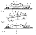
- the illustrated assembly 1 has a push rod element 2, which recesses 3, 4 contains.
- the push rod element 2 has passage openings 5, 6 formed as elongated holes.
- a transverse slide guide element 7 is pushed through the passage opening 6 with a first of two guide means 8, 9.
- the cross slide guide element 7 is aligned with respect to the push rod element 2 by inserting a detachable alignment aid 10 from behind into an alignment aid 11 of the push rod element 2 designed as a passage opening.
- a holding portion 12 of the cross slide guide element 7 is behind or under the push rod element 2.
- a nose 14 is inserted into the recess 4 of the push rod element 2.
- the assembled fitting part 13 is coupled for movement with the push rod element 2.
- the fitting part 20 also has a nose 21, the dimensions of which are adapted to the recess 3.
- the cross slide 15 has a notch trained orientation aid 25, which ensures the correct installation of the cross slide 15. This is advantageous in particular in the case of asymmetrical control slot 17.
- the cross slide guide element 7 can be fastened by clipping into the guide 28.
- clip portions 34, 35 are provided on the holding element 12, which clip into the associated clip receptacles of the guide 28 by corresponding pressure. If now the push rod element 2 is acted upon in the axial direction 36 with a force and thereby moved, the alignment aid 10 is sheared off. As a result, a relative movement of the push rod element 2 to the cross slide guide element 7 is possible.
- the assembly 1 is intended to be used in an upper end region of a sliding door. Therefore, a slider 38 is still mounted.
- the slider 38 should be arranged stationary with respect to the guide 28. Furthermore, he should not hinder the axial movement of the push rod element 2. Therefore, the trained as a slot 5 passage opening is provided, through which the slider 38 can be inserted with a mounting portion 39.
- the slider 38 is fastened in the exemplary embodiment via a screw connection 40.
- anti-rotation means which are designed as pins 41, 42, are provided, which protrude into corresponding receptacles of the guide 28.
- the push rod element 2 with a push rod element of an adjacent module be movably coupled by attaching a connector to adjacent connectors of the two assemblies.
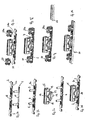
- FIGS. 2a to 2c Mounting steps for producing an end assembly of a fitting assembly are shown.
- the assembly 50 is intended for use in the lower end region of a sliding door. Components that correspond to components of the assembly 1 are designated by the same reference numerals. Since the assembly 50 is to be used at the lower end of a sliding door, the slider must be replaced by a carriage 51.
- the carriage 51 in turn has a mounting portion 52 which projects through the passage opening 5 and can be screwed from behind by means of a screw 40 with the guide 28.
- a single screw 53 is sufficient, since a rotation of the carriage 51 is excluded.
- There protrude cones 41, 42 through corresponding openings of the guide 28. Through them, a rotation lock is realized. Since the assembly 50 is an end assembly, a single connector 20 component is sufficient for motion coupling with an adjacent assembly.
- the control slot 17 is formed differently than in the cross slide 15 of the assembly 1. This is related to the operation of each driven by the cross slide 15 seal assembly.
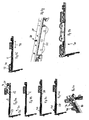
- FIGS. 3a to 3h the assembly of a designed as a center assembly of a fitting assembly assembly 60 is shown.
- the push rod element 2 has two recesses 3, 3a for lugs 21, 21a of components 20, 20a designed as connectors. Since the module 60 acts as a center module, a push rod element of an adjacent module must be coupled to the push rod element 2 on both sides in each case. Therefore, two components 20, 20a are provided.
- the adjacent assembly may be another center assembly or an end or corner assembly.
- the cross slide guide element 7 Before attaching the control unit, consisting of component 13, cross slide 15 and control pin 16, the cross slide guide element 7 is arranged from the rear of the push rod element 2, wherein the first and second guide means 8, 9 pass through the openings formed as slots 6, 6a.
- the alignment aid 10 engages in the alignment 11, so that when applying the control unit, the nose 14 automatically enters the recess 4 when the guide means 18, 19 are inserted into the guide means 8, 9.
- the entire still loosely assembled arrangement consisting of push rod element 2, components 20, 20a, control unit and cross slide guide element 7 is inserted together in a cross-sectionally C-shaped guide 28, whereby the components 20, 20a and 13 are held captive on the push rod 2.
- the cross slide guide element 7 is clipped to the guide 28.
- the cross slide guide element 7 is held immovably on the guide 28.
- the cross slide guide element 7 and the push rod element 2 are immovable relative to one another via the alignment aids 10, 11 which act as a displacement safeguard.
- the position of the push rod element 2 is fixed. It can not move unintentionally and the components 20, 20a, 13 can not "fall out” because the push rod element 2 can not slip out of the guide 28. Only when the assemblies 60 are mounted, for example, in a fitting part of a sash, the components 20, 20a are connected via a rigid connecting element with an adjacent assembly 60.
- the displacement protection ensures that when connecting adjacent components 20, 20a of adjacent subassemblies 60, the guide means 8, 9 are arranged centrally in the passage openings 6, 6a. Only when all adjacent formed as a connector components 20, 20a are motion-coupled, the anti-displacement device is destroyed.
- FIGS. 4a to 4h the assembly of a designed as a corner assembly assembly 70, which can be arranged in the lower corner of a sliding door, is shown.
- the push rod element 2 is coupled for movement with a corner drive 71.
- a movement of the push rod member 72, which can be driven via a control handle is transmitted by a flexible push rod member 73 to the push rod member 2, wherein a deflection of the movement takes place from a vertical to a horizontal movement.
- the components 20, 13 and the cross slide guide element 7 are arranged on the push rod element 2. Subsequently, the entire assembly is inserted into a guide 28 ( Fig. 4c ).
- a longitudinal slide 75 is fastened to a connecting element 74 of the corner drive 71. Since it is not easy to attach a cross slide guide element 7 in the corner region of the corner drive 71, as in the Fig. 4e shown, a guide member 76 disposed in the corner. This guide element 76 engages, as in the Fig. 4f can be seen, in a slot 77 of the cross slide 78 and holds it immobile in the folding longitudinal direction 79.
- the cross slide 78 is placed on the longitudinal slide 75 and held on this via a control pin, which passes through a through hole 80.
- the push rod element 2 has a passage opening 5 for receiving the attachment portion of a carriage 51. This is fastened via a screw 40 to the guide 28.
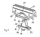
- FIG. 5 an exploded view of a control device is shown.
- Trained as a longitudinal slide member 13 has a nose 14.
- Laterally U-shaped recesses 81, 82 are provided, the make it possible to approach with the component 13 as close as possible to the guide means 18, 19 of the cross slide 15.
- the guide means 18, 19 are designed as pins, which can engage in corresponding formed as sleeves guide means of the cross slide guide element 7.
- the component 13 has a control pin receptacle 83 into which the control pin 16 can be inserted.
- the control pin 16 also passes through a control slot 17 in the cross slide 15. In axially fixed cross slide 15, therefore, a transverse movement of the cross slide 15 is generated by a longitudinal movement of the component 13.
- sealing elements of a seal assembly can be attached.
- the longitudinal slide 13 has a bearing surface 84 with which it can rest on the push rod element 2.
Landscapes
- Engineering & Computer Science (AREA)
- Mechanical Engineering (AREA)
- Window Of Vehicle (AREA)
- Securing Of Glass Panes Or The Like (AREA)
- Power-Operated Mechanisms For Wings (AREA)
- Connection Of Plates (AREA)
Description
- Die Erfindung betrifft eine Beschlaganordnung eines Fensters, einer Tür oder dergleichen nach dem Oberbegriff des Anspruchs 1.
- Das Dokument
EP 0 208 993 A offenbart eine Beschlaganordnung gemäß dem Oberbegriff des Anspruchs 1. - Beschlaganordnungen sind häufig falzseitig bei einem Fenster oder einer Tür oder dergleichen angeordnet. Durch solche Beschlaganordnungen müssen in der Regel durch ein Bedienelement eingeleitete Kräfte oder Bewegungen auf Beschlagteile entlang des Falzes des Fenster oder der Türe übertragen werden. So ist es bekannt, eine Beschlaganordnung an einem Flügel oder einer festen Einfassung des Fensters oder der Türe zu montieren, wobei eine Führung fest an dem Flügel oder der festen Einfassung angeordnet ist und ein Schubstangenelement relativ zu dieser Führung beweglich ist. Das Schubstangenelement ist in oder an der Führung geführt. An dem Schubstangenelement sind ein oder mehrere Beschlagteile angeordnet, durch die eine bestimmte Funktion ausgeführt wird. Je nach Funktion müssen mehrere Beschlagteile an dem Schubstangenelement angeordnet werden und mit diesem bewegungsgekoppelt werden. Hierzu ist es beispielsweise bekannt, Beschlagteile an dem Schubstangenelement anzuschrauben. Dies ist mit einem erheblichen Montageaufwand verbunden.
- Aufgabe der vorliegenden Erfindung ist es, eine Beschlaganordnung zu schaffen, die mit geringem Werkzeugeinsatz montiert werden kann.
- Gelöst wird diese Aufgabe durch eine Beschlaganordnung der eingangs genannten Art, bei der sowohl das Schubstangenelement als auch die Nase von zumindest einem Schenkelabschnitt der Schenkel hintergriffen sind. Dies bedeutet, dass das Beschlagteil nicht unmittelbar mit dem Schubstangenelement verbunden werden muss. Es kann während der Montage bzw. dem Zusammenbau der Beschlaganordnung relativ lose in oder an dem Schubstangenelement sitzen. Insbesondere kann das Beschlagteil mit seiner Nase in die Ausnehmung eingesteckt werden. Das Beschlagteil wird im montierten Zustand durch die Führung an dem Schubstangenelement gehalten. Das Beschlagteil wird zur Montage einfach auf das Schubstangenelement aufgesetzt, so dass die Nase in die Ausnehmung ragt und zusammen mit dem Schubstangenelement in die Führung eingeführt wird. Nach dem Einführen in die Führung wird das Beschlagteil durch die Schenkel der Führung, gehalten. Dadurch ist eine werkzeugfreie Montage möglich. Das Beschlagteil ist unverlierbar an dem Schubstangenelement angeordnet. Dadurch, dass die Nase in die Ausnehmung ragt, sind das Schubstangenelement und das Beschlagteil auch bewegungsgekoppelt.
- Die im Querschnitt C-förmige Führung kann als C-Profil ausgebildet sein. Alternativ ist es denkbar, dass die im Querschnitt C-förmige Führung mehrteilig ausgebildet ist. Insbesondere kann sie aus zwei im Querschnitt U-förmigen Profilen zusammengesetzt sein. Es ist weiterhin denkbar, als Führung eine Beschlagteilnut vorzusehen, die im Abstand vom Nutgrund von den Nutflanken hervorstehende Stege aufweist, die die Schenkel der Führung bilden.
- Das Schubstangenelement ist in der Regel zwischen zwei Endpositionen, d.h. in Grenzen entlang der Führung beweglich. Es kann daher ausreichend sein, die Schenkel nicht vollständig entlang der Führung auszubilden, sondern sie nur in denjenigen Bereichen als Schenkelabschnitte vorzusehen, in denen die Beschlagteile entlang der Führung bewegt werden. Mit anderen Worten bedeutet dies, dass sichergestellt sein muss, dass die Nasen bei allen möglichen Bewegungen des Schubstangenelements in Eingriff mit den Ausnehmungen gehalten werden.
- Vorzugsweise entspricht die Stärke der Nase etwa der Stärke des Schubstangenelements. Insbesondere sind die Dicke der Nase und eines Hintergreifabschnitts des Schubstangenelements etwa auf die nutartige Ausnehmung der im Querschnitt C-förmigen Führung abgestimmt. Somit können das Schubstangenelement und das Beschlagteil im Wesentlichen spielfrei in der Führung angeordnet werden.
- Bei der bevorzugten Ausgestaltung der Erfindung ist vorgesehen, dass die Ausmaße der Nase auf die Ausnehmung angepasst sind. Dadurch ist das Beschlagteil in Bewegungsrichtung des Schubstangenelements, d.h. in axialer Richtung,spielfrei angeordnet. Es können unterschiedlich dimensionierte Ausnehmungen für unterschiedliche Nasen unterschiedlicher Beschlagteile vorgesehen sein. Dadurch kann sichergestellt werden, dass ein bestimmtes Beschlagteil nur an der richtigen Stelle des Schubstangenelements angeordnet werden kann. Dadurch wird der Zusammenbau der Beschlaganordnung erleichtert. Insbesondere können die Nasen passgenau in den Ausnehmungen angeordnet sein.
- Bei einer besonders bevorzugten Ausführungsform kann ein Querschieberführungselement vorgesehen sein, das gemeinsam mit dem Schubstangenelement in der C-förmigen Führung montierbar ist.
- Ein Querschieberführungselement muss in der Regel ortsfest, insbesondere ortsfest gegenüber der Führung, angeordnet sein. Dies bedeutet, dass das Schubstangenelement relativ zum Querschieberführungselement verschiebbar sein muss. Das Querschieberführungselement und das Schubstangenelement getrennt voneinander in oder an der Führung zu montieren, erweist sich als schwierig. Die Montage kann daher vereinfacht werden, wenn das Querschieberführungselement und das Schubstangenelement gemeinsam montiert werden können, da das Querschieberführungselement bereits vor der endgültigen Montage bezüglich des Schubstangenelements richtig angeordnet werden kann.
- Bei einer Weiterbildung kann vorgesehen sein, dass das Querschieberführungselement mit einem Halteabschnitt hinter dem Schubstangenelement angeordnet ist, an der Führung befestigbar ist und mit zumindest einem Führungsmittel für einen Querschieber eine Durchgangsöffnung des Schubstangenelements durchgreift. Insbesondere bei dieser Weiterbildung wird klar, dass es vorteilhaft ist, das Querschieberführungselement gemeinsam mit dem Schubstangenelement zu montieren. Das Querschieberführungselement ist mit einem Halteabschnitt hinter dem Schubstangenelement angeordnet. Dies bedeutet, dass im montierten Zustand der Halteabschnitt zwischen dem Schubstangenelement und der C-förmigen Führung angeordnet ist. Das Schubstangenelement weist vorzugsweise ein Langloch auf, durch das das Führungsmittel ragt. Somit ist sichergestellt, dass das Schubstangenelement relativ zum Querschieberführungselement beweglich ist.
- Eine besonders einfache Montage ergibt sich, wenn das Querschieberführungselement in die zumindest abschnittsweise im Querschnitt C-förmige Führung eingeklipst ist. Dies bedeutet, dass das Querschieberführungselement zusammen mit dem Schubstangenelement und einem oder mehreren Beschlagteilen in die C-förmige Führung eingeführt werden kann. Anschließend kann das Querschieberführungselement auf einfache Art und Weise an der C-förmigen Führung befestigt werden, in dem es dort einfach in entsprechender Klipsaufnahmen eingeklipst wird. Dazu ist z.B. lediglich ein Krafteintrag auf das Querschieberführungselement senkrecht zur Erstreckung der Führung notwendig.
- Die Montage wird weiterhin vereinfacht, wenn das Querschieberführungselement eine Ausrichthilfe zur Ausrichtung bezüglich dem Schubstangenelement während der Montage der Beschlaganordnung aufweist.
- Bei einer vorteilhaften Ausgestaltung kann vorgesehen sein, dass die Ausrichthilfe mit einer entsprechenden Ausrichthilfe des Schubstangenelements zusammenwirkt und eine Verschiebesicherung bildet, um ein ungewolltes axiales Verschieben des Querschieberführungselements bezüglich des Schubstangenelements bei der Montage zu verhindern. Bei der Montage der zusammengebauten Baugruppe, beispielsweise an einem Flügel eines Fensters, verhindert die Verschiebesicherung wegen des ortsfesten Querschieberführungselements ein Verschieben des Schubstangenelements relativ zu Führung.
- Wenn die Ausrichthilfen so zusammenwirken, dass sie eine Verschiebesicherung bilden, stellt sich das Problem, dass nach erfolgter Montage das Schubstangenelement bezüglich des Querschieberführungselements unbeweglich ist. Für die ordnungsgemäße Funktion der Beschlaganordnung ist es jedoch notwendig, dass eine Relativbewegung der beiden Bautelemente zueinander möglich ist. Deshalb ist es vorteilhaft, wenn die Verschiebesicherung zerstörbar ist, insbesondere eine der Ausrichthilfen abscherbar ausgebildet ist. Die Ausrichthilfe ist dabei stabil genug, die gegenseitige Ausrichtung der Bauteile während der Montage sicherzustellen. Durch einen entsprechenden Krafteintrag kann die Verschiebesicherung gelöst werden. Auf besonders einfache Art und Weise lässt sich die Verschiebesicherung lösen, wenn die Ausrichthilfe entfernt wird. Dazu kann sie beispielsweise abscherbar oder mit einer Sollbruchstelle ausgestaltet sein. Beispielsweise kann die Ausrichthilfe als Zapfen ausgebildet sein, der in eine als Ausnehmung ausgebildete Ausrichthilfe des Schubstangenelements ragt, und der durch eine Bewegung des Schubstangenelements abgeschert wird.
- Besonders bevorzugt ist es, wenn ein Querschieber vorgesehen ist, der über ein als Längsschieber ausgebildetes Bauteil und einen Steuerzapfen an dem Schubstangenelement gehalten ist. Dabei weist der Querschieber vorzugsweise Führungsmittel auf, die durch entsprechende Führungsmittel des Querschieberführungselements geführt sind. Der Querschieber ist dadurch schräg zur Bewegungsrichtung des Schubstangenelements verschiebbar. Durch den Quer- und Längsschieber lässt sich eine Längsbewegung der Schubstange in eine Querbewegung des Querschiebers umsetzen. Dazu ist in dem Querschieber oder in dem Längsschieber ein Steuerschlitz ausgebildet, in dem der Steuerzapfen geführt ist. Der Steuerzapfen ist an demjenigen Schieber, der keinen Steuerschlitz aufweist, fest angeordnet. Über den Steuerzapfen sind der Längs- und Querschieber miteinander verbunden bzw. aneinander gehalten, so dass es ausreichend ist, den Längsschieber unverlierbar an dem Schubstangenelement anzuordnen. Insbesondere kann der Längsschieber ein Beschlagteil sein, das eine Nase aufweist, die in eine entsprechende Ausnehmung des Schubstangenelements ragt. An dem Querschieber können Dichtungselemente einer Dichtungsanordnung angeordnet werden, so dass die Beschlaganordnung zur Steuerung der Dichtungsanordnung eingesetzt werden kann, um gezielt einen Spalt zwischen Fenster- oder Türflügel und einer festen Einfassung für Luftdurchtritt zu öffnen oder gegen Luftdurchtritt zu verschließen.
- Vorteilhafterweise weisen der Querschieber und/oder der Längsschieber eine Orientierungshilfe auf. Der Steuerschlitz in dem Querschieber oder dem Längsschieber kann je nach Anwendungsfall unsymmetrisch ausgebildet sein. Um den seitenrichtigen Einbau sicherzustellen, kann eine Markierung vorgesehen sein, die dem Monteur anzeigt, wie der Längsschieber bzw. der Querschieber richtigerweise einzubauen ist.
- Wenn an der zumindest abschnittsweise im Querschnitt C-förmigen Führung wenigstens ein Gleiter oder ein Laufwagen befestigt sind, kann die Beschlaganordnung besonders einfach bei Schiebetüren eingesetzt werden. Dabei kann der Laufwagen am bodenseitigen Ende des Fensters oder der Türe vorgesehen sein und der Gleiter am oberen Ende.
- Es bestehen mehrere Möglichkeiten, den Laufwagen oder den Gleiter zu befestigen. Besonders vorteilhaft ist es, wenn der Laufwagen oder der Gleiter mit der Führung verschraubt oder verklipst sind. Bei einer Verklipsung kann die Beschlaganordnung weitestgehend ohne Werkzeug zusammengebaut werden. Jedoch selbst, wenn der Laufwagen oder der Gleiter mit der Führung verschraubt sind, ist der Einsatz von Werkzeug bei der Montage der Beschlaganordnung minimiert. Insbesondere kann vorgesehen sein, dass der Gleiter und der Laufwagen jeweils nur mit einer Schraube befestigt sind.
- Besonders bevorzugt ist es, wenn eine Eckumlenkung vorgesehen ist, die mit dem Schubstangenelement verbunden ist. Insbesondere, wenn die Beschlaganordnung bei einer Schiebetüre eingesetzt wird, die eine steuerbare Dichtungsanordnung im horizontal verlaufenden Falzbereich aufweist, muss häufig eine an einem Bedienelement eingebrachte Bewegung auf die Beschlaganordnung zur Steuerung der Dichtungsanordnung übertragen werden, wobei das Bedienelement beispielsweise an einem vertikalen Holm des Tür- oder Fensterflügels angeordnet ist. Eine dort eingebrachte Bewegung lässt sich besonders einfach über eine Eckumlenkung auf eine in oder an einem horizontalen Holm des Tür- oder Fensterflügels angeordnete Beschlaganordnung übertragen.
- Bei einer besonders vorteilhaften Ausführungsform der Erfindung sind mehrere Baugruppen vorgesehen, wobei mindestens eine Baugruppe eine zumindest abschnittsweise im Querschnitt C-förmige Führung und ein Schubstangenelement aufweist und das Schubstangenelement mit einem Schubstangenelement einer benachbarten Baugruppe bewegungsgekoppelt ist. Durch diese Maßnahme kann eine Materialersparnis erzielt werden. Beispielsweise muss die C-förmige Führung sich nicht entlang der gesamten Fenster- oder Türbreite erstrecken. Es ist ausreichend, eine Führung an den Stellen vorzusehen, wo Beschlagteile notwendig sind. Es können Baugruppen für unterschiedliche Einsatzzwecke und Einsatzorte zusammengebaut werden, wobei verschiedene Baugruppen gleiche oder ähnliche Bauteile verwenden können. Insbesondere können in den Eckbereichen des Fensters oder der Türe Endbaugruppen vorgesehen sein und zur Überbrückung größerer Strecken zwischen den Endbaugruppen können Mittelbaugruppen vorgesehen sein, wobei die Schubstangenelemente der Baugruppen über Verbindungselemente bewegungsgekoppelt sind.
- Die Erfindung wird nachfolgend anhand der Figuren der Zeichnung näher erläutert. Es zeigen:
- Fig. 1a
- eine perspektivische Ansicht eines Schubstangenelements und eines Querschieberführungselements einer Baugruppe einer Beschlaganordnung vor der Montage der Baugruppe;
- Fig. 1b
- einen Montageschritt bei der Herstellung der Beschlaganordnung, wobei das Querschieberführungselement an dem Schubstangenelement angeordnet ist;
- Fig. 1c
- die Beschlaganordnung mit an dem Schubstangenelement angeordnetem Verbinder und Querschieber;
- Fig. 1d
- eine Darstellung zur Verdeutlichung der Montage des Schubstangenelements zusammen mit weiteren Beschlagteilen in einer im Querschnitt C-förmigen Führung;
- Fig. 1e
- eine Darstellung zur Verdeutlichung der Montage eines Gleiters;
- Fig. 1f
- eine Draufsicht auf die Rückseite der im Querschnitt C-förmigen Führung zur Verdeutlichung der Montage des Gleiters;
- Fig. 1g
- die fertigmontierte Baugruppe der Beschlaganordnung;
- Fig. 2a
- eine Ansicht einer Baugruppe einer Beschlaganordnung zur Darstellung der Montage eines Laufwagens;
- Fig. 2b
- eine perspektivische Draufsicht auf die Rückseite der Baugruppe zur Darstellung der Montage des Laufwagens;
- Fig. 2c
- eine Ausführungsform einer Baugruppe einer Beschlaganordnung;
- Fig. 3a
- ein Schubstangenelement und ein Querschieberführungselement einer Baugruppe einer Beschlaganordnung vor der Montage;
- Fig. 3b
- das auf das Querschieberführungselement aufgesetzte Schubstangenelement;
- Fig. 3c
- einen Querschieber und einen Längsschieber vor der Anordnung des Querschiebers an dem Querschieberführungselement;
- Fig. 3d
- den an dem Querschieberführungselement angeordneten Querschieber;
- Fig. 3e
- die Anordnung der
Fig. 3d mit zwei daran anzuordnenden Verbindern; - Fig. 3f
- die Anordnung der
Fig. 3d mit daran angeordneten Verbindern; - Fig. 3g
- eine Darstellung zur Verdeutlichung der Montage der Anordnung der
Fig. 3f in einer im Querschnitt C-förmigen Führung; - Fig. 3h
- eine fertigmontierte Mittenbaugruppe einer Beschlaganordnung;
- Fig. 4a
- eine Darstellung zur Verdeutlichung der Montage einer Eckbaugruppe einer Beschlaganordnung mit einer Eckumlenkung;
- Fig. 4b
- die Endbaugruppe der
Fig. 4a mit daran angeordnetem Querschieber und Verbinder; - Fig. 4c
- die Anordnung der
Fig. 4b mit einer im Querschnitt C-förmigen Führung; - Fig. 4d
- die Anordnung der
Fig. 4c mit an der Eckumlenkung angeordnetem Längsschieber; - Fig. 4e
- eine Detaildarstellung des Eckbereichs der Eckumlenkung;
- Fig. 4f
- eine Darstellung der Anordnung der
Fig. 4d mit an dem Längsschieber angebrachtem Querschieber; - Fig. 4g
- eine perspektivische Ansicht zur Darstellung der Verbindung eines Laufwagens;
- Fig. 4h
- eine Ansicht einer fertigmontierten Eckbaugruppe einer Beschlaganordnung;
- Fig. 5
- eine Explosionsdarstellung einer Steuereinheit bestehend aus Längsschieber, Querschieber und Steuerzapfen.
- Anhand der
Fign. 1a bis 1g wird die Montage einer Endbaugruppe einer Beschlaganordnung dargestellt. Die dargestellte Baugruppe 1 weist ein Schubstangenelement 2 auf, welches Ausnehmungen 3, 4 enthält. Das Schubstangenelement 2 hat als Langlöcher ausgebildete Durchgangsöffnungen 5, 6. Zu Beginn der Montage wird ein Querschieberführungselement 7 mit einem ersten von zwei Führungsmitteln 8, 9 durch die Durchgangsöffnung 6 geschoben. Das Querschieberführungselement 7 wird gegenüber dem Schubstangenelement 2 ausgerichtet, indem eine abscherbare Ausrichthilfe 10 von hinten in eine als Durchgangsöffnung ausgebildete Ausrichthilfe 11 des Schubstangenelements 2 eingeführt wird. - In der
Fig. 1b ist gezeigt, wie das Querschieberführungselement 7 an dem Schubstangenelement 2 angeordnet ist. Dabei liegt ein Halteabschnitt 12 des Querschieberführungselements 7 hinter bzw. unter dem Schubstangenelement 2. Anschließend wird ein als Längsschieber ausgebildetes Beschlagteil 13 aufgesetzt, wobei eine Nase 14 in die Ausnehmung 4 des Schubstangenelements 2 eingesetzt wird. Über die Nase 14 und die Ausnehmung 4 ist das montierte Beschlagteil 13 mit dem Schubstangenelement 2 bewegungsgekoppelt. - An dem Beschlagteil 13 ist ein Querschieber 15 über einen Steuerzapfen 16, der in einem Steuerschlitz 17 des Querschiebers 15 geführt ist, gehalten. Beim Aufsetzen des Beschlagteils 13 gelangen als Zapfen ausgebildete Führungsmittel 18, 19 in die als Führungshülsen ausgebildeten Führungsmittel 8, 9. Da das Querschieberführungselement 7 über die Ausrichthilfen 10, 11 bereits richtig zum Schubstangenelement 2 ausgerichtet ist, kommen die Nase 14 und die Führungsmittel 18, 19 bei der Montage ohne weiteres in Eingriff mit der Ausnehmung 4 und den Führungsmitteln 8, 9.
- Weiterhin wird ein als Verbinder ausgebildetes Beschlagteil 20 aufgesetzt. Das Beschlagteil 20 weist ebenfalls eine Nase 21 auf, deren Ausmaße auf die Ausnehmung 3 angepasst sind.
- Der Querschieber 15 weist eine als Kerbe ausgebildete Orientierungshilfe 25 auf, die den korrekten Einbau des Querschiebers 15 sicherstellt. Dies ist insbesondere bei unsymmetrischem Steuerschlitz 17 vorteilhaft.
- Aus der
Fig. 1d ist ersichtlich, dass die gesamte Anordnung bestehend aus Schubstangenelement 2, Beschlagteilen 13, 20, Querschieberführungselement 7, Querschieber 15 und Steuerzapfen 16 gemeinsam in eine als C-Profil ausgebildete im Querschnitt C-förmige Führung 28 eingeführt werden. Im eingeführten Zustand hintergreifen die Schenkel 29, 30 der Führung 28, die mit dem Führungsgrund 33 eine nutartige Ausnehmung bilden, Hintergreifabschnitte 31 des Schubstangenelements 2 und die Nasen 14, 21. Das Schubstangenelement 2 ist stufenförmig ausgebildet. Insbesondere steht der Bereich 32 nach oben über die Hintergreifabschnitte 31 vor, so dass ein genügend großer Zwischenraum zwischen dem Bereich 32 und dem Grund 33 der Führung 28 für den Halteabschnitt 12 des Querschieberführungselement 7 verbleibt. - Nach der Einführung in die Führung 28 kann das Querschieberführungselement 7 durch Einklipsen in die Führung 28 befestigt werden. Dafür sind am Halteelement 12 Klipsabschnitte 34, 35 vorgesehen, die durch entsprechenden Druck in zugeordnete Klipsaufnahmen der Führung 28 einrasten. Wird nun das Schubstangenelement 2 in axialer Richtung 36 mit einer Kraft beaufschlagt und dadurch bewegt, wird die Ausrichthilfe 10 abgeschert. Dadurch ist eine Relativbewegung des Schubstangenelements 2 zum Querschieberführungselement 7 möglich.
- Die Baugruppe 1 soll in einem oberen Endbereich einer Schiebetüre eingesetzt werden. Deshalb wird noch ein Gleiter 38 montiert. Der Gleiter 38 soll bezüglich der Führung 28 ortsfest angeordnet sein. Weiterhin soll er die axiale Bewegung des Schubstangenelements 2 nicht behindern. Deshalb ist die als Langloch 5 ausgebildete Durchgangsöffnung vorgesehen, durch die der Gleiter 38 mit einem Befestigungsabschnitt 39 hindurchgesteckt werden kann. Rückseitig ist der Gleiter 38 im Ausführungsbeispiel über eine Schraubverbindung 40 befestigt. Um ein Verdrehen des Gleiters 38 zu verhindern, sind Drehsicherungsmittel, die als Zapfen 41, 42 ausgebildet sind, vorgesehen, die in entsprechende Aufnahmen der Führung 28 hineinragen. Über den Verbinder 20 kann das Schubstangenelement 2 mit einem Schubstangenelement einer benachbarten Baugruppe bewegungsgekoppelt werden, indem ein Verbindungselement an benachbarten Verbindern der beiden Baugruppen befestigt wird.
- In den
Fign. 2a bis 2c sind Montageschritte zur Herstellung einer Endbaugruppe einer Beschlaganordnung gezeigt. Die Baugruppe 50 ist zum Einsatz im unteren Endbereich einer Schiebetüre vorgesehen. Bauelemente, die Bauelementen der Baugruppe 1 entsprechen, sind mit denselben Bezugszeichen bezeichnet. Da die Baugruppe 50 am unteren Ende einer Schiebetüre eingesetzt werden soll, muss der Gleiter durch einen Laufwagen 51 ersetzt werden. Der Laufwagen 51 weist wiederum einen Befestigungsabschnitt 52 auf, der durch die Durchgangsöffnung 5 ragt und von hinten mittels einer Schraubverbindung 40 mit der Führung 28 verschraubt werden kann. Eine einzige Schraube 53 ist ausreichend, da ein Verdrehen des Laufwagens 51 ausgeschlossen ist. Es ragen Zapfen 41, 42 durch entsprechende Durchbrüche der Führung 28. Durch sie wird eine Drehsicherung realisiert. Da es sich bei der Baugruppe 50 um eine Endbaugruppe handelt, ist ein einziges als Verbinder ausgebildetes Bauteil 20 zur Bewegungskopplung mit einer benachbarten Baugruppe ausreichend. Der Steuerschlitz 17 ist anders ausgebildet als bei dem Querschieber 15 der Baugruppe 1. Dies hängt mit der Funktionsweise der jeweils durch den Querschieber 15 angetriebenen Dichtungsanordnung zusammen. - In den
Fign. 3a bis 3h ist die Montage einer als Mittenbaugruppe einer Beschlaganordnung ausgebildeten Baugruppe 60 dargestellt. Für Bauelemente, die Bauelementen derFig. 1 entsprechen, werden wieder dieselben Bezugszeichen verwendet. Das Schubstangenelement 2 weist zwei Ausnehmungen 3, 3a für Nasen 21, 21a von als Verbinder ausgebildeten Bauteilen 20, 20a auf. Da die Baugruppe 60 als Mittenbaugruppe fungiert, muss beidseits jeweils ein Schubstangenelement einer benachbarten Baugruppe mit dem Schubstangenelement 2 bewegungsgekoppelt werden. Deshalb sind zwei Bauteile 20, 20a vorgesehen. Bei der benachbarten Baugruppe kann es sich um eine weitere Mittenbaugruppe oder um eine End- oder Eckbaugruppe handeln. Vor dem Anbringen der Steuereinheit, bestehend aus Bauteil 13, Querschieber 15 und Steuerzapfen 16, wird das Querschieberführungselement 7 von hinten an dem Schubstangenelement 2 angeordnet, wobei das erste und zweite Führungsmittel 8, 9 die als Langlöcher ausgebildeten Durchgangsöffnungen 6, 6a durchgreifen. Dabei greift die Ausrichthilfe 10 in die Ausrichthilfe 11 ein, so dass beim Aufbringen der Steuereinheit die Nase 14 automatisch in die Ausnehmung 4 gelangt, wenn die Führungsmittel 18, 19 in die Führungsmittel 8, 9 eingeführt werden. Die gesamte noch lose zusammengesetzte Anordnung bestehend aus Schubstangenelement 2, Bauteilen 20, 20a, Steuereinheit und Querschieberführungselement 7 wird gemeinsam in eine im Querschnitt C-förmige Führung 28 eingeführt, wodurch die Bauteile 20, 20a und 13 unverlierbar an der Schubstange 2 gehalten werden. - Nach dem Einführen der Anordnung wird das Querschieberführungselement 7 mit der Führung 28 verklipst. Dadurch ist das Querschieberführungselement 7 unverschieblich an der Führung 28 gehalten. In diesem Zustand sind das Querschieberführungselement 7 und das Schubstangenelement 2 über die als Verschiebesicherung wirkenden Ausrichthilfen 10, 11 zueinander unbeweglich. Dies bedeutet, dass die Position des Schubstangenelementes 2 festgelegt ist. Es kann sich nicht ungewollt verstellen und die Bauteile 20, 20a, 13 können nicht "herausfallen", da das Schubstangenelement 2 nicht aus der Führung 28 rutschen kann. Erst, wenn die Baugruppen 60 beispielsweise in einer Beschlagteilnut eines Flügelrahmens montiert ist, werden die Bauteile 20, 20a über ein starres Verbindungselement mit einer benachbarten Baugruppe 60 verbunden. Durch die Verschiebesicherung wird sichergestellt, dass beim Verbinden benachbarter Bauteile 20, 20a benachbarter Baugruppen 60 die Führungsmittel 8, 9 mittig in den Durchgangsöffnungen 6, 6a angeordnet sind. Erst, wenn alle benachbarten als Verbinder ausgebildete Bauteile 20, 20a bewegungsgekoppelt sind, wird die Verschiebesicherung zerstört.
- In den
Fign. 4a bis 4h wird die Montage einer als Eckbaugruppe ausgebildeten Baugruppe 70, die im unteren Eckbereich einer Schiebetüre angeordnet werden kann, dargestellt. Das Schubstangenelement 2 ist mit einer Eckumlenkung 71 bewegungsgekoppelt. Eine Bewegung des Schubstangenelements 72, das über einen Bediengriff angetrieben werden kann, wird durch ein flexibles Schubstangenelement 73 an das Schubstangenelement 2 übertragen, wobei eine Umlenkung der Bewegung von einer vertikalen in eine horizontale Bewegung erfolgt. In gleicher Weise wie zuvor beschrieben, werden die Bauteile 20, 13 sowie das Querschieberführungselement 7 an dem Schubstangenelement 2 angeordnet. Anschließend wird die gesamte Anordnung in eine Führung 28 eingeschoben (Fig. 4c ). Daraufhin wird auf ein Verbindungselement 74 der Eckumlenkung 71 ein Längsschieber 75 befestigt. Da sich im Eckbereich der Eckumlenkung 71 ein Querschieberführungselement 7 nicht einfach anbringen lässt, wird, wie in derFig. 4e dargestellt, ein Führungselement 76 im Eckbereich angeordnet. Dieses Führungselement 76 greift, wie dies in derFig. 4f zu erkennen ist, in einen Schlitz 77 des Querschiebers 78 ein und hält diesen in Falzlängsrichtung 79 unbeweglich fest. Der Querschieber 78 ist auf den Längsschieber 75 aufgesetzt und an diesem über einen Steuerzapfen, der eine Durchgangsöffnung 80 durchgreift, gehalten. Das Schubstangenelement 2 weist eine Durchgangsöffnung 5 zur Aufnahme des Befestigungsabschnitts eines Laufwagens 51 auf. Dieser wird über eine Schraubverbindung 40 an der Führung 28 befestigt. - In der
Fig. 5 ist eine Explosionsdarstellung einer Steuereinrichtung dargestellt. Das als Längsschieber ausgebildete Bauteil 13 weist eine Nase 14 auf. Seitlich sind U-förmige Ausnehmungen 81, 82 vorgesehen, die es erlauben, mit dem Bauteil 13 möglichst nahe an die Führungsmittel 18, 19 des Querschiebers 15 heranzufahren. Die Führungsmittel 18, 19 sind als Zapfen ausgebildet, die in entsprechende als Hülsen ausgebildete Führungsmittel des Querschieberführungselements 7 eingreifen können. Das Bauteil 13 weist eine Steuerzapfenaufnahme 83 auf, in die der Steuerzapfen 16 einführbar ist. Der Steuerzapfen 16 durchgreift außerdem einen Steuerschlitz 17 im Querschieber 15. Bei axial feststehendem Querschieber 15 wird durch eine Längsbewegung des Bauteils 13 daher eine Querbewegung des Querschiebers 15 erzeugt. An dem Querschieber 15 können Dichtungselemente einer Dichtungsanordnung befestigt werden. Der Längsschieber 13 weist eine Auflagefläche 84 auf, mit der er auf dem Schubstangenelement 2 aufliegen kann.
Claims (15)
- Beschlaganordnung eines Fensters, einer Tür oder dgl. mit einer zumindest abschnittsweise im Querschnitt C-förmig ausgebildeten Führung (28), welche im Abstand vom Führungsgrund (33) von den Nutflanken hervorstehende Schenkel (29, 30) aufweist, mit einem durch die Führung (28) geführten Schubstangenelement (2) und zumindest einem mit dem Schubstangenelement (2) bewegungsgekoppelten Beschlagteil (13, 20, 20a), wobei das Schubstangenelement (2) zumindest eine Ausnehmung (3, 4) und das Beschlagteil (13, 20, 20a) zumindest eine In die Ausnehmung (3, 4) ragende Nase (14, 21, 21a) aufweist, wobei das Beschlagteil (13, 20, 20a) über die Nase (14, 21, 21a) und die Ausnehmung (3, 4) mit dem Schubstangenelement (2) bewegungsgekoppelt ist, dadurch gekennzeichnet, dass sowohl das Schubstangenelement (2) als auch die Nase (14, 21, 21a) von zumindest einem Schenkelabschnitt der Schenkel (29, 30) hintergriffen sind.
- Beschlaganordnung nach Anspruch 1, dadurch gekennzeichnet, dass die Stärke der Nase (14, 21, 21a) etwa der Stärke des Schubstangenelements (2) entspricht.
- Beschlaganordnung nach Anspruch 1 oder 2, dadurch gekennzeichnet, dass die Ausmaße der Nase (14, 21, 21a) auf die Ausnehmung (3, 4) angepasst sind.
- Beschlaganordnung nach einem der vorhergehenden Ansprüche, dadurch gekennzeichnet, dass ein Querschieberführungselement (7) vorgesehen ist, das gemeinsam mit dem Schubstangenelement (2) in der zumindest abschnittsweise im Querschnitt C-förmigen Führung (28) montierbar ist.
- Beschlaganordnung nach Anspruch 4, dadurch gekennzeichnet, dass das Querschieberführungselement (7) mit einem Halteabschnitt (12) hinter dem Schubstangenelement (2) angeordnet ist, an der Führung (28) befestigbar ist und mit zumindest einem Führungsmittel (8, 9) für einen Querschieber (15) eine Durchgangsöffnung (6, 6a) des Schubstangenelements (2) durchgreift.
- Beschlaganordnung nach Anspruch 4 oder 5, dadurch gekennzeichnet, dass das Querschieberführungselement (7) in die zu-mindest abschnittsweise im Querschnitt C-förmige Führung (28) eingeklipst ist.
- Beschlaganordnung nach einem der vorhergehenden Ansprüche 4 bis 6, dadurch gekennzeichnet, dass das Querschieberführungselement (7) eine Ausrichthilfe (10) zur Ausrichtung bezüglich dem Schubstangenelement (2) während der Montage der Beschlaganordnung aufweist.
- Beschlaganordnung nach Anspruch 7, dadurch gekennzeichnet, dass die Ausrichthilfe (10) mit einer entsprechenden Ausrichthilfe (11) des Schubstangenelements (2) zusammenwirkt und eine Verschiebesicherung bildet, um ein axiales Verschieben des Querschieberführungselements (7) bezüglich des Schubstangenelements bei der Montage zu verhindern.
- Beschlaganordnung nach Anspruch 8, dadurch gekennzeichnet, dass die Verschiebesicherung zerstörbar ist, insbesondere eine der Ausrichthilfen (10, 11) abscherbar ausgebildet ist.
- Beschlaganordnung nach einem der vorhergehenden Ansprüche, dadurch gekennzeichnet, dass ein Querschieber (15) vorgesehen ist, der über ein als Längsschieber ausgebildetes Bauteil (13) und einen Steuerzapfen (16) an dem Schubstangenelement (2) gehalten ist.
- Beschlaganordnung nach Anspruch 10, dadurch gekennzeichnet, dass der Querschieber (15) und/oder der Längsschieber (13) eine Orientierungshilfe (25) aufweist.
- Beschlaganordnung nach einem der vorhergehenden Ansprüche, dadurch gekennzeichnet, dass an der zumindest abschnittsweise im Querschnitt C-förmigen Führung (28) ein Gleiter (38) oder ein Laufwagen (51) befestigt ist.
- Beschlaganordnung nach Anspruch 12, dadurch gekennzeichnet, dass der Laufwagen (51) oder der Gleiter (38) mit der Führung (28) befestigt, insbesondere verschraubt oder verklipst sind.
- Beschlaganordnung nach einem der vorhergehenden Ansprüche, dadurch gekennzeichnet, dass zumindest eine Eckumlenkung (71) vorgesehen ist, die mit dem Schubstangenelement (2) verbunden ist.
- Beschlaganordnung nach einem der vorhergehenden Ansprüche, dadurch gekennzeichnet, dass mehrere Baugruppen (1, 50, 60, 70) vorgesehen sind, wobei mindestens eine Baugruppe eine zumindest abschnittsweise im Querschnitt C-förmige Führung (28) und ein Schubstangenelement (2) aufweist und das Schubstangenelement (2) mit einem Schubstangenelement (2) einer benachbarten Baugruppe (1, 50, 60, 70) bewegungsgekoppelt ist.
Priority Applications (1)
| Application Number | Priority Date | Filing Date | Title |
|---|---|---|---|
| PL05017157T PL1635019T5 (pl) | 2004-09-11 | 2005-08-06 | Układ okuć dla okna, drzwi lub temu podobnych |
Applications Claiming Priority (1)
| Application Number | Priority Date | Filing Date | Title |
|---|---|---|---|
| DE102004043942A DE102004043942A1 (de) | 2004-09-11 | 2004-09-11 | Beschlaganordnung für ein Fenster, eine Tür oder dergleichen |
Publications (4)
| Publication Number | Publication Date |
|---|---|
| EP1635019A2 EP1635019A2 (de) | 2006-03-15 |
| EP1635019A3 EP1635019A3 (de) | 2006-04-12 |
| EP1635019B1 EP1635019B1 (de) | 2007-10-17 |
| EP1635019B2 true EP1635019B2 (de) | 2013-10-23 |
Family
ID=35482598
Family Applications (1)
| Application Number | Title | Priority Date | Filing Date |
|---|---|---|---|
| EP05017157.8A Expired - Lifetime EP1635019B2 (de) | 2004-09-11 | 2005-08-06 | Beschlaganordnung für ein Fenster, eine Tür oder dergleichen |
Country Status (4)
| Country | Link |
|---|---|
| EP (1) | EP1635019B2 (de) |
| AT (1) | ATE376112T1 (de) |
| DE (2) | DE102004043942A1 (de) |
| PL (1) | PL1635019T5 (de) |
Families Citing this family (1)
| Publication number | Priority date | Publication date | Assignee | Title |
|---|---|---|---|---|
| CA3093608A1 (en) * | 2019-09-17 | 2021-03-17 | Truth Hardware Corporation | Tie bar and guide for casement window |
Citations (7)
| Publication number | Priority date | Publication date | Assignee | Title |
|---|---|---|---|---|
| DE2217458C2 (de) † | 1971-04-15 | 1982-06-03 | Manfred 4972 Löhne Mühle | Beschlag für Fenster, Türen o.dgl. mit einer Halterung für Betätigungsschienen |
| DE29920094U1 (de) † | 1999-11-15 | 2000-02-10 | Siegenia-Frank Kg, 57074 Siegen | Beschlag eines zumindest behebbaren, vorzugsweise aber auch bewegbaren Flügels eines Fensters oder einer Tür |
| EP1002919B1 (de) † | 1998-11-20 | 2002-11-27 | Siegenia-Frank Kg | Treibstangenbeschlag für Fenster, Türen od. dgl. |
| EP1219768B1 (de) † | 2000-12-13 | 2004-04-28 | Euroinvest S.r.L. | Mechanische Verbindungsanordnung für Umfangsverriegelungsvorrichtung von einbruchsicheren aus Metallprofilen bestehenden Tür- und Fensterflügeln |
| EP1447505A2 (de) † | 2001-01-29 | 2004-08-18 | van Parys, Remi Emiel | Fensterbeschlag |
| DE10345758A1 (de) † | 2003-10-01 | 2005-04-21 | Wicona Bausysteme Gmbh | Beschlag für den Flügelrahmen eines Fensters, einer Tür o. dgl. |
| EP1491706B1 (de) † | 2003-06-27 | 2006-11-02 | SAVIO S.p.A. | Kraftübertragungsgestänge für Zubehörteile für Türe und Fenster |
Family Cites Families (6)
| Publication number | Priority date | Publication date | Assignee | Title |
|---|---|---|---|---|
| CH437727A (de) * | 1964-10-21 | 1967-06-15 | Gretsch Unitas Gmbh | Fensterflügelrahmen mit in mindestens einer Rahmenleiste längs verschiebbarer Schiene |
| DE2426030C2 (de) * | 1974-05-30 | 1986-09-11 | Winkhaus, August, 4404 Telgte | Ausstellvorrichtung für ein Drehkippfenster |
| AT373342B (de) * | 1974-05-30 | 1984-01-10 | Winkhaus Fa August | Befestigungswinkel eines schubstangeneckumlenkers |
| DE3525705A1 (de) * | 1985-07-18 | 1987-01-22 | Winkhaus Fa August | Paarung von verriegelungselementen an einem fenster einer tuer oder dergleichen |
| FR2747150B1 (fr) * | 1996-04-04 | 1998-08-07 | Ferco Int Usine Ferrures | Cremone ou cremone-serrure, notamment du type multipoints |
| EP0945580B1 (de) * | 1998-03-25 | 2005-11-09 | Siegenia-Aubi Kg | Beschlag für Fenster oder Türen |
-
2004
- 2004-09-11 DE DE102004043942A patent/DE102004043942A1/de not_active Withdrawn
-
2005
- 2005-08-06 DE DE502005001709T patent/DE502005001709D1/de not_active Expired - Lifetime
- 2005-08-06 PL PL05017157T patent/PL1635019T5/pl unknown
- 2005-08-06 AT AT05017157T patent/ATE376112T1/de active
- 2005-08-06 EP EP05017157.8A patent/EP1635019B2/de not_active Expired - Lifetime
Patent Citations (7)
| Publication number | Priority date | Publication date | Assignee | Title |
|---|---|---|---|---|
| DE2217458C2 (de) † | 1971-04-15 | 1982-06-03 | Manfred 4972 Löhne Mühle | Beschlag für Fenster, Türen o.dgl. mit einer Halterung für Betätigungsschienen |
| EP1002919B1 (de) † | 1998-11-20 | 2002-11-27 | Siegenia-Frank Kg | Treibstangenbeschlag für Fenster, Türen od. dgl. |
| DE29920094U1 (de) † | 1999-11-15 | 2000-02-10 | Siegenia-Frank Kg, 57074 Siegen | Beschlag eines zumindest behebbaren, vorzugsweise aber auch bewegbaren Flügels eines Fensters oder einer Tür |
| EP1219768B1 (de) † | 2000-12-13 | 2004-04-28 | Euroinvest S.r.L. | Mechanische Verbindungsanordnung für Umfangsverriegelungsvorrichtung von einbruchsicheren aus Metallprofilen bestehenden Tür- und Fensterflügeln |
| EP1447505A2 (de) † | 2001-01-29 | 2004-08-18 | van Parys, Remi Emiel | Fensterbeschlag |
| EP1491706B1 (de) † | 2003-06-27 | 2006-11-02 | SAVIO S.p.A. | Kraftübertragungsgestänge für Zubehörteile für Türe und Fenster |
| DE10345758A1 (de) † | 2003-10-01 | 2005-04-21 | Wicona Bausysteme Gmbh | Beschlag für den Flügelrahmen eines Fensters, einer Tür o. dgl. |
Also Published As
| Publication number | Publication date |
|---|---|
| EP1635019B1 (de) | 2007-10-17 |
| DE502005001709D1 (de) | 2007-11-29 |
| ATE376112T1 (de) | 2007-11-15 |
| DE102004043942A1 (de) | 2006-03-30 |
| PL1635019T3 (pl) | 2008-03-31 |
| EP1635019A2 (de) | 2006-03-15 |
| EP1635019A3 (de) | 2006-04-12 |
| PL1635019T5 (pl) | 2014-03-31 |
Similar Documents
| Publication | Publication Date | Title |
|---|---|---|
| EP3165703A2 (de) | Absenkbare dichtungsvorrichtung | |
| DE2313690A1 (de) | Treibstangenbeschlag fuer fenster, tueren od.dgl | |
| EP3535824B1 (de) | Sammelschienenhalter und eine entsprechende anordnung | |
| EP3266969B1 (de) | Eckumlenkung eines beschlages für einen flügel eines fensters oder einer tür | |
| EP0843064B1 (de) | Beschlag für ein Fenster | |
| EP1264954B1 (de) | Verriegelungsvorrichtung | |
| EP3071896A1 (de) | Haltevorrichtung für ein gehäuse und verfahren zur montage des gehäuses unter verwendung der haltevorrichtung | |
| DE202008004032U1 (de) | Fenster oder Tür | |
| EP1635019B2 (de) | Beschlaganordnung für ein Fenster, eine Tür oder dergleichen | |
| EP4105432B1 (de) | Automatische dichtung mit einem führungselement zum führen einer schubstange und verfahren zum positionieren des führungselementes in einem gehäuse der dichtung | |
| DE3225049C2 (de) | Treibstangenverschluß | |
| EP2754803B1 (de) | Riegelstangenbeschlag für ein Fenster oder eine Tür und Riegelstange für einen solchen Riegelstangenbeschlag | |
| EP4074931B1 (de) | Beschlag mit einem durch längsschieben arretierbaren rasthaken | |
| DE19859546A1 (de) | Schieberstangenbefestigungs- und -führungselement | |
| EP0833028B1 (de) | Gleitführungs-Anschlagstück für Öffnungsbegrenzer von Fenster- und Türflügeln | |
| EP4146888A1 (de) | Scharnierbaugruppe mit gemeinsamer betätigung | |
| EP2317047A2 (de) | Beschlaganordnung | |
| EP1746235B1 (de) | Beschlaganordnung | |
| EP1580370B1 (de) | Beschlaganordnung | |
| EP1580371B1 (de) | Beschlaganordnung | |
| EP4219873B1 (de) | Gebäudeverschlusseinrichtung sowie verfahren zum montieren einer gebäudeverschlusseinrichtung | |
| DE2461228A1 (de) | Verschlussvorrichtung fuer fenster, tueren oder dergleichen | |
| DE102021125772B4 (de) | Abstandhalter, Führungsschiene für einen Raffstore oder eine Jalousie sowie Raffstore und Jalousie und Verfahren hierfür | |
| EP1626150B1 (de) | Dichtungsanordnung | |
| DE102004043973B3 (de) | Verfahren zur Verbindung von Baugruppen einer Beschlaganordnung in einer Beschlagteilnut eines Tür- oder Fensterflügels |
Legal Events
| Date | Code | Title | Description |
|---|---|---|---|
| PUAI | Public reference made under article 153(3) epc to a published international application that has entered the european phase |
Free format text: ORIGINAL CODE: 0009012 |
|
| PUAL | Search report despatched |
Free format text: ORIGINAL CODE: 0009013 |
|
| AK | Designated contracting states |
Kind code of ref document: A2 Designated state(s): AT BE BG CH CY CZ DE DK EE ES FI FR GB GR HU IE IS IT LI LT LU LV MC NL PL PT RO SE SI SK TR |
|
| AX | Request for extension of the european patent |
Extension state: AL BA HR MK YU |
|
| AK | Designated contracting states |
Kind code of ref document: A3 Designated state(s): AT BE BG CH CY CZ DE DK EE ES FI FR GB GR HU IE IS IT LI LT LU LV MC NL PL PT RO SE SI SK TR |
|
| AX | Request for extension of the european patent |
Extension state: AL BA HR MK YU |
|
| 17P | Request for examination filed |
Effective date: 20060810 |
|
| AKX | Designation fees paid |
Designated state(s): AT BE BG CH CY CZ DE DK EE ES FI FR GB GR HU IE IS IT LI LT LU LV MC NL PL PT RO SE SI SK TR |
|
| GRAP | Despatch of communication of intention to grant a patent |
Free format text: ORIGINAL CODE: EPIDOSNIGR1 |
|
| GRAS | Grant fee paid |
Free format text: ORIGINAL CODE: EPIDOSNIGR3 |
|
| GRAA | (expected) grant |
Free format text: ORIGINAL CODE: 0009210 |
|
| AK | Designated contracting states |
Kind code of ref document: B1 Designated state(s): AT BE BG CH CY CZ DE DK EE ES FI FR GB GR HU IE IS IT LI LT LU LV MC NL PL PT RO SE SI SK TR |
|
| REG | Reference to a national code |
Ref country code: GB Ref legal event code: FG4D Free format text: NOT ENGLISH |
|
| REG | Reference to a national code |
Ref country code: CH Ref legal event code: EP |
|
| REG | Reference to a national code |
Ref country code: IE Ref legal event code: FG4D Free format text: LANGUAGE OF EP DOCUMENT: GERMAN |
|
| REF | Corresponds to: |
Ref document number: 502005001709 Country of ref document: DE Date of ref document: 20071129 Kind code of ref document: P |
|
| ET | Fr: translation filed | ||
| REG | Reference to a national code |
Ref country code: PL Ref legal event code: T3 |
|
| PG25 | Lapsed in a contracting state [announced via postgrant information from national office to epo] |
Ref country code: ES Free format text: LAPSE BECAUSE OF FAILURE TO SUBMIT A TRANSLATION OF THE DESCRIPTION OR TO PAY THE FEE WITHIN THE PRESCRIBED TIME-LIMIT Effective date: 20080128 Ref country code: SE Free format text: LAPSE BECAUSE OF FAILURE TO SUBMIT A TRANSLATION OF THE DESCRIPTION OR TO PAY THE FEE WITHIN THE PRESCRIBED TIME-LIMIT Effective date: 20080117 |
|
| GBV | Gb: ep patent (uk) treated as always having been void in accordance with gb section 77(7)/1977 [no translation filed] | ||
| PG25 | Lapsed in a contracting state [announced via postgrant information from national office to epo] |
Ref country code: PT Free format text: LAPSE BECAUSE OF FAILURE TO SUBMIT A TRANSLATION OF THE DESCRIPTION OR TO PAY THE FEE WITHIN THE PRESCRIBED TIME-LIMIT Effective date: 20080317 Ref country code: SI Free format text: LAPSE BECAUSE OF FAILURE TO SUBMIT A TRANSLATION OF THE DESCRIPTION OR TO PAY THE FEE WITHIN THE PRESCRIBED TIME-LIMIT Effective date: 20071017 Ref country code: BG Free format text: LAPSE BECAUSE OF FAILURE TO SUBMIT A TRANSLATION OF THE DESCRIPTION OR TO PAY THE FEE WITHIN THE PRESCRIBED TIME-LIMIT Effective date: 20080117 Ref country code: LV Free format text: LAPSE BECAUSE OF FAILURE TO SUBMIT A TRANSLATION OF THE DESCRIPTION OR TO PAY THE FEE WITHIN THE PRESCRIBED TIME-LIMIT Effective date: 20071017 Ref country code: IS Free format text: LAPSE BECAUSE OF FAILURE TO SUBMIT A TRANSLATION OF THE DESCRIPTION OR TO PAY THE FEE WITHIN THE PRESCRIBED TIME-LIMIT Effective date: 20080217 Ref country code: LT Free format text: LAPSE BECAUSE OF FAILURE TO SUBMIT A TRANSLATION OF THE DESCRIPTION OR TO PAY THE FEE WITHIN THE PRESCRIBED TIME-LIMIT Effective date: 20071017 |
|
| REG | Reference to a national code |
Ref country code: IE Ref legal event code: FD4D |
|
| PLBI | Opposition filed |
Free format text: ORIGINAL CODE: 0009260 |
|
| PG25 | Lapsed in a contracting state [announced via postgrant information from national office to epo] |
Ref country code: DK Free format text: LAPSE BECAUSE OF FAILURE TO SUBMIT A TRANSLATION OF THE DESCRIPTION OR TO PAY THE FEE WITHIN THE PRESCRIBED TIME-LIMIT Effective date: 20071017 |
|
| 26 | Opposition filed |
Opponent name: SIEGENIA-AUBI KG Effective date: 20080711 |
|
| PLAX | Notice of opposition and request to file observation + time limit sent |
Free format text: ORIGINAL CODE: EPIDOSNOBS2 |
|
| PG25 | Lapsed in a contracting state [announced via postgrant information from national office to epo] |
Ref country code: SK Free format text: LAPSE BECAUSE OF FAILURE TO SUBMIT A TRANSLATION OF THE DESCRIPTION OR TO PAY THE FEE WITHIN THE PRESCRIBED TIME-LIMIT Effective date: 20071017 Ref country code: RO Free format text: LAPSE BECAUSE OF FAILURE TO SUBMIT A TRANSLATION OF THE DESCRIPTION OR TO PAY THE FEE WITHIN THE PRESCRIBED TIME-LIMIT Effective date: 20071017 |
|
| PG25 | Lapsed in a contracting state [announced via postgrant information from national office to epo] |
Ref country code: IE Free format text: LAPSE BECAUSE OF FAILURE TO SUBMIT A TRANSLATION OF THE DESCRIPTION OR TO PAY THE FEE WITHIN THE PRESCRIBED TIME-LIMIT Effective date: 20071017 |
|
| PGFP | Annual fee paid to national office [announced via postgrant information from national office to epo] |
Ref country code: NL Payment date: 20080828 Year of fee payment: 4 |
|
| NLR1 | Nl: opposition has been filed with the epo |
Opponent name: SIEGENIA-AUBI KG |
|
| PG25 | Lapsed in a contracting state [announced via postgrant information from national office to epo] |
Ref country code: GB Free format text: LAPSE BECAUSE OF FAILURE TO SUBMIT A TRANSLATION OF THE DESCRIPTION OR TO PAY THE FEE WITHIN THE PRESCRIBED TIME-LIMIT Effective date: 20071017 |
|
| PLBB | Reply of patent proprietor to notice(s) of opposition received |
Free format text: ORIGINAL CODE: EPIDOSNOBS3 |
|
| PG25 | Lapsed in a contracting state [announced via postgrant information from national office to epo] |
Ref country code: GR Free format text: LAPSE BECAUSE OF FAILURE TO SUBMIT A TRANSLATION OF THE DESCRIPTION OR TO PAY THE FEE WITHIN THE PRESCRIBED TIME-LIMIT Effective date: 20080118 |
|
| PGFP | Annual fee paid to national office [announced via postgrant information from national office to epo] |
Ref country code: TR Payment date: 20080725 Year of fee payment: 4 |
|
| PG25 | Lapsed in a contracting state [announced via postgrant information from national office to epo] |
Ref country code: FI Free format text: LAPSE BECAUSE OF FAILURE TO SUBMIT A TRANSLATION OF THE DESCRIPTION OR TO PAY THE FEE WITHIN THE PRESCRIBED TIME-LIMIT Effective date: 20071017 |
|
| PGFP | Annual fee paid to national office [announced via postgrant information from national office to epo] |
Ref country code: BE Payment date: 20080908 Year of fee payment: 4 |
|
| PG25 | Lapsed in a contracting state [announced via postgrant information from national office to epo] |
Ref country code: MC Free format text: LAPSE BECAUSE OF NON-PAYMENT OF DUE FEES Effective date: 20080831 |
|
| PG25 | Lapsed in a contracting state [announced via postgrant information from national office to epo] |
Ref country code: EE Free format text: LAPSE BECAUSE OF FAILURE TO SUBMIT A TRANSLATION OF THE DESCRIPTION OR TO PAY THE FEE WITHIN THE PRESCRIBED TIME-LIMIT Effective date: 20071017 |
|
| PG25 | Lapsed in a contracting state [announced via postgrant information from national office to epo] |
Ref country code: CY Free format text: LAPSE BECAUSE OF FAILURE TO SUBMIT A TRANSLATION OF THE DESCRIPTION OR TO PAY THE FEE WITHIN THE PRESCRIBED TIME-LIMIT Effective date: 20071017 |
|
| BERE | Be: lapsed |
Owner name: ROTO FRANK A.G. Effective date: 20090831 |
|
| REG | Reference to a national code |
Ref country code: NL Ref legal event code: V1 Effective date: 20100301 |
|
| PG25 | Lapsed in a contracting state [announced via postgrant information from national office to epo] |
Ref country code: BE Free format text: LAPSE BECAUSE OF NON-PAYMENT OF DUE FEES Effective date: 20090831 |
|
| PG25 | Lapsed in a contracting state [announced via postgrant information from national office to epo] |
Ref country code: HU Free format text: LAPSE BECAUSE OF FAILURE TO SUBMIT A TRANSLATION OF THE DESCRIPTION OR TO PAY THE FEE WITHIN THE PRESCRIBED TIME-LIMIT Effective date: 20080418 Ref country code: NL Free format text: LAPSE BECAUSE OF NON-PAYMENT OF DUE FEES Effective date: 20100301 Ref country code: LU Free format text: LAPSE BECAUSE OF NON-PAYMENT OF DUE FEES Effective date: 20080806 |
|
| PLAY | Examination report in opposition despatched + time limit |
Free format text: ORIGINAL CODE: EPIDOSNORE2 |
|
| PLBC | Reply to examination report in opposition received |
Free format text: ORIGINAL CODE: EPIDOSNORE3 |
|
| PG25 | Lapsed in a contracting state [announced via postgrant information from national office to epo] |
Ref country code: TR Free format text: LAPSE BECAUSE OF NON-PAYMENT OF DUE FEES Effective date: 20090806 |
|
| PUAH | Patent maintained in amended form |
Free format text: ORIGINAL CODE: 0009272 |
|
| STAA | Information on the status of an ep patent application or granted ep patent |
Free format text: STATUS: PATENT MAINTAINED AS AMENDED |
|
| 27A | Patent maintained in amended form |
Effective date: 20131023 |
|
| AK | Designated contracting states |
Kind code of ref document: B2 Designated state(s): AT BE BG CH CY CZ DE DK EE ES FI FR GB GR HU IE IS IT LI LT LU LV MC NL PL PT RO SE SI SK TR |
|
| REG | Reference to a national code |
Ref country code: CH Ref legal event code: AELC |
|
| REG | Reference to a national code |
Ref country code: DE Ref legal event code: R102 Ref document number: 502005001709 Country of ref document: DE Effective date: 20131023 |
|
| PG25 | Lapsed in a contracting state [announced via postgrant information from national office to epo] |
Ref country code: LV Free format text: LAPSE BECAUSE OF FAILURE TO SUBMIT A TRANSLATION OF THE DESCRIPTION OR TO PAY THE FEE WITHIN THE PRESCRIBED TIME-LIMIT Effective date: 20131023 |
|
| REG | Reference to a national code |
Ref country code: FR Ref legal event code: PLFP Year of fee payment: 12 |
|
| REG | Reference to a national code |
Ref country code: FR Ref legal event code: PLFP Year of fee payment: 13 |
|
| PGFP | Annual fee paid to national office [announced via postgrant information from national office to epo] |
Ref country code: RO Payment date: 20170518 Year of fee payment: 13 |
|
| PGFP | Annual fee paid to national office [announced via postgrant information from national office to epo] |
Ref country code: AT Payment date: 20170821 Year of fee payment: 13 |
|
| REG | Reference to a national code |
Ref country code: FR Ref legal event code: PLFP Year of fee payment: 14 |
|
| REG | Reference to a national code |
Ref country code: CH Ref legal event code: PL |
|
| REG | Reference to a national code |
Ref country code: AT Ref legal event code: MM01 Ref document number: 376112 Country of ref document: AT Kind code of ref document: T Effective date: 20180806 |
|
| PG25 | Lapsed in a contracting state [announced via postgrant information from national office to epo] |
Ref country code: CZ Free format text: LAPSE BECAUSE OF NON-PAYMENT OF DUE FEES Effective date: 20180806 Ref country code: AT Free format text: LAPSE BECAUSE OF NON-PAYMENT OF DUE FEES Effective date: 20180806 Ref country code: CH Free format text: LAPSE BECAUSE OF NON-PAYMENT OF DUE FEES Effective date: 20180831 Ref country code: LI Free format text: LAPSE BECAUSE OF NON-PAYMENT OF DUE FEES Effective date: 20180831 |
|
| PGFP | Annual fee paid to national office [announced via postgrant information from national office to epo] |
Ref country code: IT Payment date: 20190821 Year of fee payment: 15 Ref country code: FR Payment date: 20190822 Year of fee payment: 15 |
|
| PGFP | Annual fee paid to national office [announced via postgrant information from national office to epo] |
Ref country code: PL Payment date: 20190725 Year of fee payment: 15 |
|
| PG25 | Lapsed in a contracting state [announced via postgrant information from national office to epo] |
Ref country code: FR Free format text: LAPSE BECAUSE OF NON-PAYMENT OF DUE FEES Effective date: 20200831 |
|
| PG25 | Lapsed in a contracting state [announced via postgrant information from national office to epo] |
Ref country code: IT Free format text: LAPSE BECAUSE OF NON-PAYMENT OF DUE FEES Effective date: 20200806 |
|
| PG25 | Lapsed in a contracting state [announced via postgrant information from national office to epo] |
Ref country code: PL Free format text: LAPSE BECAUSE OF NON-PAYMENT OF DUE FEES Effective date: 20200806 |
|
| PGFP | Annual fee paid to national office [announced via postgrant information from national office to epo] |
Ref country code: DE Payment date: 20230822 Year of fee payment: 19 |
|
| REG | Reference to a national code |
Ref country code: DE Ref legal event code: R119 Ref document number: 502005001709 Country of ref document: DE |
|
| PG25 | Lapsed in a contracting state [announced via postgrant information from national office to epo] |
Ref country code: DE Free format text: LAPSE BECAUSE OF NON-PAYMENT OF DUE FEES Effective date: 20250301 |