EP1634983A2 - Polbildungsverfahren und Polbildungsvorrrichtung in Frottierwebmaschinen mit bewegbarem Tuch - Google Patents
Polbildungsverfahren und Polbildungsvorrrichtung in Frottierwebmaschinen mit bewegbarem Tuch Download PDFInfo
- Publication number
- EP1634983A2 EP1634983A2 EP05018297A EP05018297A EP1634983A2 EP 1634983 A2 EP1634983 A2 EP 1634983A2 EP 05018297 A EP05018297 A EP 05018297A EP 05018297 A EP05018297 A EP 05018297A EP 1634983 A2 EP1634983 A2 EP 1634983A2
- Authority
- EP
- European Patent Office
- Prior art keywords
- driving
- weaving
- pile
- cloth
- loom
- Prior art date
- Legal status (The legal status is an assumption and is not a legal conclusion. Google has not performed a legal analysis and makes no representation as to the accuracy of the status listed.)
- Withdrawn
Links
Images


Classifications
-
- D—TEXTILES; PAPER
- D03—WEAVING
- D03D—WOVEN FABRICS; METHODS OF WEAVING; LOOMS
- D03D39/00—Pile-fabric looms
- D03D39/22—Terry looms
- D03D39/223—Cloth control
Definitions
- the present invention relates to a pile-formation method and a pile-formation device in a cloth-shifting-type pile loom.
- Japanese Unexamined Patent Application Publication No. 2-47334 discloses an example of a cloth-shifting-type pile loom.
- a guide roller 4 defining a let-off-side terry motion member for guiding ground warp yarns and a breast beam 6 defining a take-up-side terry motion member for guiding woven cloth are respectively driven by servo-motors 37, 36.
- a control operation of the guide roller 4 includes shedding compensation.
- the term "shedding compensation" refers to an operation for compensating for a change (an increase) in warp tension caused by a shedding motion.
- Japanese Unexamined Patent Application Publication No. 11-172552 Another example of a cloth-shifting-type pile loom is disclosed in Japanese Unexamined Patent Application Publication No. 11-172552.
- a ground-warp tension roller 7 defining a let-off-side terry motion member and a take-up-side terry motion member are controlled in an asynchronous fashion. It is disclosed that this structure allows for compensation for a change in warp tension caused by a shedding motion.
- the phrase “shedding compensation is performed” is written in the specification of Japanese Unexamined Patent Application Publication No. 2-47334, the specification does not have any detailed description concerning the phrase.
- the terry motion members are driven by a cam mechanism, which is driven by a main shaft. Consequently, according to this structure, the difference in driving modes (i.e. driving distances, driving timings, and driving speeds) between the terry motion members is always constant for the driving operations of the terry motion members.
- a let-off-side terry motion member ground-warp tension roller
- a take-up-side terry motion member termeast beam / cloth guide roller
- the present invention provides a pile-formation method in a cloth-shifting-type pile loom which drives a take-up-side terry motion member and a let-off-side terry motion member individually with designated first and second electrical actuators, respectively.
- the pile-formation method includes the steps of driving the second electrical actuator for the let-off-side terry motion member and the first electrical actuator for the take-up-side terry motion member in an asynchronous manner, wherein a driving condition corresponding to each of a plurality of weaving conditions is set for at least one of the electrical actuators such that a magnitude of a difference in driving amounts between the electrical actuators varies depending on weaving operations performed under different weaving conditions; and changing the driving condition of one of or each of the electrical actuators when a weaving condition is switched to another weaving condition during a weaving operation.
- the designated electrical actuators are generally defined by servo-motors, but are not limited to servo-motors.
- the electrical actuators may be any type of actuators as long as they are capable of electrically controlling the driving distances.
- the asynchronous driving operations may alternatively be performed based on different driving timings (drive-start timings and drive-end timings) or on different speed patterns (speed patterns when shifting between a forward-limit position and a backward-limit position). Consequently, the term "driving condition" for each electrical actuator includes the driving distance, the driving timing, and the driving speed.
- the term "weaving condition” includes a plurality of weaving-related parameters.
- the "weaving-related parameters” include, for example, a shedding pattern, a rotational speed of the loom, a weft density, a weft type, a warp tension, a shifting distance of cloth (pile length), and the number of pile picks.
- the term "a plurality of weaving conditions” refers to two or more weaving conditions, such that at least one of the weaving-related parameters is different between the weaving conditions.
- the present invention also provides a pile-formation device in a cloth-shifting-type pile loom.
- the pile-formation device includes a first electrical actuator for driving a take-up-side terry motion member; a second electrical actuator for driving a let-off-side terry motion member; a driving-condition setting device for setting driving conditions for the first electrical actuator and the second electrical actuator; and drive-control means for driving the electrical actuators based on the driving conditions set in the driving-condition setting device.
- the cloth-shifting-type pile loom drives the first electrical actuator and the second electrical actuator in an asynchronous manner based on different driving conditions so that the take-up-side terry motion member and the let-off-side terry motion member are driven in different modes.
- the driving-condition setting device sets a plurality of driving conditions for at least one of the electrical actuators.
- each weaving condition may include a rotational speed of the loom, a weft density, a weft type, a shifting distance of cloth, and the number of pile picks.
- at least one of the rotational speed of the loom, the weft density, the weft type, the shifting distance of cloth, and the number of pile picks is different between the weaving conditions.
- each driving condition may be set in view of at least two of a shedding pattern, a rotational speed of the loom, a weft density, and a weft type.
- the first electrical actuator and the second electrical actuator are driven asynchronously so that the take-up-side terry motion member and the let-off-side terry motion member are driven in different modes. Moreover, the magnitude of the difference in driving modes between the two actuators is changed in correspondence with the weaving conditions. Accordingly, the present invention has the following advantages.
- the difference in driving modes between the terry motion members is set in correspondence with the number of pile picks such that the difference in driving modes can be changed in accordance with the change in the number of pile picks. Accordingly, the problems mentioned above can be effectively prevented.
- Fig. 1 illustrates an example of a cloth-shifting-type pile loom 1 according to the present invention.
- Fig. 2 illustrates a terry motion mechanism 20 of the cloth-shifting-type pile loom 1.
- pile warp yarns 4 for pile formation are fed from an upper warp beam 2 and are wound around guide rollers 8 and a pile-warp tension roller 6 so as to be supplied to a cloth fell 11 of cloth 13 via a heald 9 and a reed 10.
- the pile-warp tension roller 6 is supported by tension-applying means 19 in a movable manner in the front-back direction such that the pile-warp tension roller 6 is biased in a direction for applying a predetermined tension to the pile warp yarns 4.
- ground warp yarns 5 for ground weaving are fed from a lower warp beam 3 and are wound around a ground-warp tension roller 7 so as to be supplied to the cloth fell 11 of the cloth 13 via the heald 9 and the reed 10.
- the pile warp yarns 4 and the ground warp yarns 5 are interwoven with each weft yarn 12 inserted in a shed, whereby the cloth 13 of pile fabric is formed.
- the cloth 13 of pile fabric is subsequently guided by a cloth guide roller 18, a take-up roller 14, a guide roller 15, and a guide roller 16 so as to be finally taken up by a cloth roller 17.
- the ground-warp tension roller 7 defines a let-off-side terry motion member
- the cloth guide roller 18 defines a take-up-side terry motion member.
- the ground-warp tension roller 7 is supported by a rocking lever unit 22 and a rocking shaft 24 in a rocking manner in the front-back direction with respect to, for example, a loom frame (not shown).
- the cloth guide roller 18 is supported by a rocking lever unit 21 and a rocking shaft 23 in a rocking manner in the front-back direction with respect to, for example, the loom frame (not shown).
- the ground-warp tension roller 7 and the cloth guide roller 18 defining the terry motion members may be unrotatable or rotatable, and are supported by the terry motion mechanism 20 in a movable manner in the front-back direction.
- the ground-warp tension roller 7 and the cloth guide roller 18 are set at a backward-limit position where the amount of terry motion is zero, that is, a first-pick position F corresponding to a beating position.
- the ground-warp tension roller 7 and the cloth guide roller 18 are set at a forward-limit position where the amount of terry motion is present, that is, a loose-pick position L.
- the first-pick position F and the loose-pick position L will be described below in detail with reference to the ground-warp tension roller 7 and the cloth guide roller 18 in Figs. 4A and 4B.
- the top ends of the rocking lever units 21, 22 are respectively linked with the top ends of two rocking lever units 36, 37 disposed at the central section of the terry motion mechanism 20. Specifically, the top ends of the rocking lever units 21, 22 are respectively linked with the top ends of two rocking lever units 36, 37 via linking rods 25, 26 and linking pins 27, 28 disposed at opposite ends of the linking rods 25, 26.
- the lengths of the linking rods 25, 26 can be adjusted with screws (not shown) provided at the opposite ends thereof.
- the rocking lever unit 36 is supported by a spindle 38 in a rotatable manner with respect to, for example, the loom frame (not shown).
- the rocking lever unit 37 is supported by a spindle 39 in a rotatable manner with respect to, for example, the loom frame (not shown).
- cranks 31, 32 are respectively linked with front end portions of cranks 31, 32 via link components 29, 30 and linking pins 33, 34 disposed at opposite ends of the link components 29, 30.
- the base end portions of the cranks 31, 32 are respectively attached to a driving shaft 40 of a first electrical actuator 41 and a driving shaft 43 of a second electrical actuator 42 in a rotatably-locked fashion.
- the first electrical actuator 41 and the second electrical actuator 42 are designated electrical actuators that operate in synchronization with the rotation of a main shaft 35 of the loom 1.
- the first electrical actuator 41 and the second electrical actuator 42 are electrical servo-motors that are individually controlled by a loom-controlling computer 50 shown in Fig. 3 in an asynchronous manner with respect to each other.
- the rotation of the first electrical actuator 41 is converted to a rocking motion by the crank 31, the link component 29, the rocking lever unit 36, the linking rod 25, and the rocking lever unit 21.
- the rocking motion is transmitted to the cloth guide roller 18 serving as the take-up-side terry motion member.
- the rotation of the second electrical actuator 42 is converted to a rocking motion by the crank 32, the link component 30, the rocking lever unit 37, the linking rod 26, and the rocking lever unit 22.
- the rocking motion is transmitted to the ground-warp tension roller 7 serving as the let-off-side terry motion member.
- the cloth guide roller 18 and the ground-warp tension roller 7 are rocked in an asynchronous manner so as to move in the front-back direction. Therefore, the cloth 13 of pile fabric is moved in the front-back direction in response to the weaving operation of the cloth-shifting-type pile loom 1, whereby the cloth fell 11 reciprocates between the first-pick position F and the loose-pick position L. Accordingly, the terry motion mechanism 20 asynchronously moves the cloth guide roller 18 and the ground-warp tension roller 7 in the front-back direction so as to change the distance between the cloth guide roller 18 and the ground-warp tension roller 7. As a result, the tension of the pile warp yarns 4 and the tension of the ground warp yarns 5 are adjusted to appropriate values for pile formation.
- the inserted weft yarn 12 is not completely beaten against the cloth fell 11 for the purpose of preparing for pile formation. Therefore, the incompletely beaten weft yarn 12 and the cloth fell 11 form a distance therebetween that corresponds to the amount of terry motion (i.e. an amount of reed clearance).
- the cloth fell 11 is at the first-pick position F, the inserted weft yarn 12 is completely beaten against the cloth fell 11.
- the cloth fell 11 is retreated to the beating position (i.e. the first-pick position F) where the weft yarn 12 is completed beaten against the cloth fell 11.
- the pile warp yarns 4 form piles having a length that corresponds to the amount of terry motion (i.e. the amount of reed clearance).
- the terry motion mechanism 20 includes the link mechanism (i.e. a combination of the crank-lever units and the lever units) which is driven based on the rotations of the first electrical actuator 41 and the second electrical actuator 42.
- the first electrical actuator 41, the second electrical actuator 42, and the link mechanism are designed to predetermined dimensions in view that desired movements are attained for the cloth guide roller 18 defining the take-up-side terry motion member and the ground-warp tension roller 7 defining the let-off-side terry motion member.
- the cloth guide roller 18 and the ground-warp tension roller 7 are capable of being reciprocated between the first-pick position F and the loose-pick position L at individual timings, or may be stopped at one of the positions F and L.
- the terry motion mechanism 20 may alternatively be defined by a combination of a cam mechanism and electrical actuators that operate in synchronization with the rotation of the main shaft 35.
- the magnitude of the difference in driving amounts between the first electrical actuator 41 and the second electrical actuator 42 varies depending on weaving operations performed under different weaving conditions.
- a driving condition corresponding to each weaving condition is set for at least one of the electrical actuators.
- the driving condition for one of or each of the electrical actuators is changed.
- Fig. 3 illustrates the loom-controlling computer 50 for controlling the driving operation of the first electrical actuator 41 and the second electrical actuator 42; a weaving-condition setting device 46 connected to an input side of the loom-controlling computer 50; a driving-condition setting device 47; a rotation detector 48, such as an encoder; and first drive-control means 44 and second drive-control means 45 which are connected to an output side of the loom-controlling computer 50.
- the first drive-control means 44 includes a control circuit 51 which receives an output from the loom-controlling computer 50 and an output from the rotation detector 48, and an amplification circuit 53 which receives an output from the control circuit 51 so as to drive the first electrical actuator 41.
- the second drive-control means 45 includes a control circuit 52 which receives an output from the loom-controlling computer 50 and an output from the rotation detector 48, and an amplification circuit 54 which receives an output from the control circuit 52 so as to drive the second electrical actuator 42.
- various set values for a plurality of weaving-related parameters included in each weaving condition are set in the loom-controlling computer 50.
- the weaving-related parameters include, for example, a shedding pattern, the rotational speed of the loom 1, the weft density, the weft type, and the warp tension.
- the weaving-related parameters are changeable. Accordingly, a plurality of condition settings can be set in the loom-controlling computer 50 with respect to at least one changeable weaving-related parameter.
- a switch timing is additionally set.
- this switch timing is set based on, for example, a cycle number in a weaving operation.
- the loom-controlling computer 50 is provided with a counter (pick counter), which is not shown, for counting the number of cycles of the loom 1.
- This pick counter performs a count-up operation every time a predetermined main-shaft angle (for example, 0°) is detected based on a signal from the rotation detector 48 provided for the main shaft 35.
- the pick counter performs a count-down operation when the main shaft 35 rotates in the reverse direction.
- the loom-controlling computer 50 Based on the set weaving condition and the set cycle number, the loom-controlling computer 50 outputs a driving signal to each of devices included in the cloth-shifting-type pile loom 1 (such as a main driving device, a weft-insertion device, a shedding device, a take-up device, and a let-off device).
- a driving signal to each of devices included in the cloth-shifting-type pile loom 1 (such as a main driving device, a weft-insertion device, a shedding device, a take-up device, and a let-off device).
- the driving-condition setting device 47 sets the driving conditions of the two electrical actuators (i.e. the first electrical actuator 41 and the second electrical actuator 42) for respectively driving the two terry motion members (i.e. the cloth guide roller 18 and the ground-warp tension roller 7).
- each driving condition includes a pile pattern (the number of pile picks and the length of the piles); the driving distance (the amount of rotation of each electrical actuator for moving the corresponding terry motion member by a predetermined distance); the driving timing (the timing for retreating each terry motion member from the forward-limit position in order to perform the beating operation for the first pick, and the end timing at which each terry motion member reaches the forward-limit position when the terry motion member is shifted from the backward-limit position toward the forward-limit position); and a speed pattern (the transition pattern of speed of each terry motion member in the process of the movement from the forward-limit position towards the backward-limit position or from the backward-limit position towards the forward-limit position).
- a pile pattern the number of pile picks and the length of the piles
- the driving distance the amount of rotation of each electrical actuator for moving the corresponding terry motion member by a predetermined distance
- the driving timing the timing for retreating each terry motion member from the forward-limit position in order to perform
- a plurality of set values can be set in the driving-condition setting device 47 with respect to a driving condition for one of or each of the first electrical actuator 41 of the take-up side and the second electrical actuator 42 of the let-off-side.
- each driving condition may include at least one of the driving distance, the driving timing, and the speed pattern.
- the loom-controlling computer 50 outputs the driving condition for the first electrical actuator 41 set in the driving-condition setting device 47 to the control circuit 51 in the first drive-control means 44, the driving condition corresponding to the current weaving condition. Based on the set timing and the set driving distance in the output driving condition, the control circuit 51 drives and controls the corresponding first electrical actuator 41 via the amplification circuit 53. Similarly, the loom-controlling computer 50 outputs the driving condition for the second electrical actuator 42 set in the driving-condition setting device 47 to the control circuit 52 in the second drive-control means 45, the driving condition corresponding to the current weaving condition. Based on the set timing and the set driving distance in the output driving condition, the control circuit 52 drives and controls the corresponding second electrical actuator 42 via the amplification circuit 54.
- the present invention may also be applied to an example in which a predetermined unit length is woven under a predetermined weaving condition and the subsequent predetermined unit length is woven under a weaving condition different from the previous weaving condition, or to an example in which multiple types of weft yarns 12 are used for the weaving operation such that the type of weft yarn 12 inserted is changed for every predetermined number of picks.
- the operation of the cloth-shifting-type pile loom 1 is performed in the same manner.
- the weaving operation is performed under two types of weaving conditions (i.e. weaving condition A and weaving condition B) between which the weft density and the weft type included in the weaving-related parameters are different. Consequently, two types of set values for each of the weft density and the weft type included in the weaving-related parameters are set in the weaving-condition setting device 46.
- the driving distance of the second electrical actuator 42 may be changed. Accordingly, two types of driving distances for the second electrical actuator 42, which correspond to the two respective weaving conditions, are set in the driving-condition setting device 47. The magnitude of each of the driving distances is set in view of the content of the corresponding weaving-related parameters in each weaving condition.
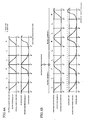
- Figs. 4A and 4B are diagrams illustrating the driving patterns of the let-off-side and take-up-side terry motion members (let-off-side tension roller 7 and take-up-side cloth guide roller 18) according to this embodiment.
- Figs. 4A and 4B illustrate an example of a triple-weft pile fabric (2L - 1F).
- one unit for pile formation includes three weft yarns, such that one unit is equal to three cycles (three rotations) of the loom 1. In each unit, one weft yarn is inserted for the first pick, and two weft yarns are inserted for the loose picks.
- the let-off-side tension roller 7 and the take-up-side cloth guide roller 18 are at the forward-limit position (loose-pick position L) when the rotational angle of the main shaft 35 is at 0°.
- the let-off-side tension roller 7 and the take-up-side cloth guide roller 18 are shifted to the backward-limit position (first-pick position F) in which the rotational angle of the main shaft 35 is at 0°.
- the let-off-side tension roller 7 and the take-up-side cloth guide roller 18 are shifted to the forward-limit position (loose-pick position L) in which the rotational angle of the main shaft 35 is at 0°.
- the let-off-side tension roller 7 and the take-up-side cloth guide roller 18 are maintained at the forward-limit position (loose-pick position L).
- the driving pattern for the cloth guide roller 18 in a moving state substantially forms a sinusoidal waveform.
- the driving pattern for the ground-warp tension roller 7 in a moving state changes drastically from the middle of the rising phase with respect to a sinusoidal waveform (indicated by a dotted line) so as to form a curve with high acceleration.
- the driving pattern changes gradually with respect to the sinusoidal waveform (indicated by the dotted line) so as to form a curve with low acceleration.
- the ground-warp tension roller 7 serving as the let-off-side terry motion member and the cloth guide roller 18 serving as the take-up-side terry motion member are driven based on different driving modes (i.e. different timings and different speed patterns in the drawings).
- the first electrical actuator 41 corresponding to the cloth guide roller 18 and the second electrical actuator 42 corresponding to the tension roller 7 are driven and controlled in an asynchronous manner.
- Fig. 4B illustrates an example in which the weaving condition is switched from weaving condition A to weaving condition B during a continuous operation of the loom 1.
- Weaving condition B has a weft density and a weft type of the weaving-related parameters that are different from those in weaving condition A.
- the weft density and the weft type in weaving condition B require higher warp tension during the beating operation for the first pick than those in weaving condition A. Therefore, as shown in Fig. 4B, the driving distance of the ground-warp tension roller 7 in weaving condition B is set in the driving-condition setting device 47 at a higher value (backward-limit position indicated by a dotted line) than that in weaving condition A.
- the loom-controlling computer 50 determines switching of the weaving conditions based on the count value of the pick counter (loom cycle number), and outputs a command signal to the relevant devices (take-up device, weft-insertion device, etc.) in order to switch the driving modes. Moreover, the loom-controlling computer 50 also outputs the driving distance corresponding to the switched condition to the control circuit 52 in the second drive-control means 45. Accordingly, under the switched weaving condition, the second drive-control means 45 controls the driving operation of the second electrical actuator 42 based on an amount of rotation greater than that in the previous weaving condition. This changes the backward shifting distance of the ground-warp tension roller 7 (let-off-side terry motion member), whereby the warp tension during the beating operation of the first pick is increased.
- the loom-controlling computer 50 outputs the driving distance corresponding to weaving condition A in response to the switching of the weaving conditions.
- the second drive-control means 45 drives the second electrical actuator 42 based on the corresponding amount of rotation.
- the cloth-shifting-type pile loom 1 drives the let-off-side terry motion member (ground-warp tension roller 7) and the take-up-side terry motion member (cloth guide roller 18) individually via the designated second electrical actuator 42 and first electrical actuator 41, respectively, such that the let-off-side second electrical actuator 42 and the take-up-side first electrical actuator 41 are driven in an asynchronous manner.
- the magnitude of the difference in driving amounts between the first electrical actuator 41 and the second electrical actuator 42 varies depending on weaving operations performed under different weaving conditions. This is achieved by setting a driving condition corresponding to each weaving condition in the weaving-condition setting device 46 for at least one of the first electrical actuator 41 and the second electrical actuator 42.
- the loom-controlling computer 50 changes the driving condition for one of or each of the first electrical actuator 41 and the second electrical actuator 42.
Landscapes
- Engineering & Computer Science (AREA)
- Textile Engineering (AREA)
- Looms (AREA)
Applications Claiming Priority (1)
| Application Number | Priority Date | Filing Date | Title |
|---|---|---|---|
| JP2004260644A JP2006077340A (ja) | 2004-09-08 | 2004-09-08 | 布移動式パイル織機におけるパイル形成方法およびその装置 |
Publications (2)
| Publication Number | Publication Date |
|---|---|
| EP1634983A2 true EP1634983A2 (de) | 2006-03-15 |
| EP1634983A3 EP1634983A3 (de) | 2007-08-01 |
Family
ID=35445858
Family Applications (1)
| Application Number | Title | Priority Date | Filing Date |
|---|---|---|---|
| EP05018297A Withdrawn EP1634983A3 (de) | 2004-09-08 | 2005-08-23 | Polbildungsverfahren und Polbildungsvorrrichtung in Frottierwebmaschinen mit bewegbarem Tuch |
Country Status (3)
| Country | Link |
|---|---|
| EP (1) | EP1634983A3 (de) |
| JP (1) | JP2006077340A (de) |
| CN (1) | CN1746355A (de) |
Cited By (1)
| Publication number | Priority date | Publication date | Assignee | Title |
|---|---|---|---|---|
| CN102899783A (zh) * | 2011-07-27 | 2013-01-30 | 津田驹工业株式会社 | 织机的织造方法和织造装置 |
Families Citing this family (3)
| Publication number | Priority date | Publication date | Assignee | Title |
|---|---|---|---|---|
| CN103437045B (zh) * | 2013-08-27 | 2015-07-08 | 山东日发纺织机械有限公司 | 一种毛巾织机起圈控制装置 |
| ITUB20152354A1 (it) * | 2015-07-21 | 2017-01-21 | Itema Spa | Dispositivo di regolazione della tensione dei fili di ordito del riccio in un telaio per la tessitura di spugna |
| CN108823762B (zh) * | 2018-09-04 | 2024-04-02 | 山东日发纺织机械有限公司 | 一种布动起毛装置及布动起毛装置动力机构 |
Citations (2)
| Publication number | Priority date | Publication date | Assignee | Title |
|---|---|---|---|---|
| JPH0247334A (ja) | 1988-07-08 | 1990-02-16 | Gebr Sulzer Ag | テリー織機を運転する方法及びテリー織機 |
| JPH11172552A (ja) | 1997-12-09 | 1999-06-29 | Tsudakoma Corp | 布移動式パイル織機の経糸張力補正方法 |
-
2004
- 2004-09-08 JP JP2004260644A patent/JP2006077340A/ja active Pending
-
2005
- 2005-08-01 CN CN 200510084578 patent/CN1746355A/zh active Pending
- 2005-08-23 EP EP05018297A patent/EP1634983A3/de not_active Withdrawn
Patent Citations (2)
| Publication number | Priority date | Publication date | Assignee | Title |
|---|---|---|---|---|
| JPH0247334A (ja) | 1988-07-08 | 1990-02-16 | Gebr Sulzer Ag | テリー織機を運転する方法及びテリー織機 |
| JPH11172552A (ja) | 1997-12-09 | 1999-06-29 | Tsudakoma Corp | 布移動式パイル織機の経糸張力補正方法 |
Cited By (3)
| Publication number | Priority date | Publication date | Assignee | Title |
|---|---|---|---|---|
| CN102899783A (zh) * | 2011-07-27 | 2013-01-30 | 津田驹工业株式会社 | 织机的织造方法和织造装置 |
| EP2551390A3 (de) * | 2011-07-27 | 2013-08-07 | Tsudakoma Kogyo Kabushiki Kaisha | Webverfahren und Webvorrichtung in einer Webmaschine |
| CN102899783B (zh) * | 2011-07-27 | 2015-05-27 | 津田驹工业株式会社 | 织机的织造方法和织造装置 |
Also Published As
| Publication number | Publication date |
|---|---|
| EP1634983A3 (de) | 2007-08-01 |
| CN1746355A (zh) | 2006-03-15 |
| JP2006077340A (ja) | 2006-03-23 |
Similar Documents
| Publication | Publication Date | Title |
|---|---|---|
| US5014756A (en) | Pile warp tension control in a loom | |
| CN1071814C (zh) | 一种用于在织机上织造纱罗织物控制经纱的装置 | |
| US7438092B2 (en) | Power loom, particularly an air jet power loom, for the production of a leno fabric with integral patterning | |
| EP0352791B1 (de) | Verfahren und Webmaschine zum Weben von Gewebe mit gekräuselter Oberfläche | |
| EP3106554B1 (de) | Verfahren zur steuerung der fachöffnung von florkettgarn auf einem florgewebewebstuhl | |
| EP1634983A2 (de) | Polbildungsverfahren und Polbildungsvorrrichtung in Frottierwebmaschinen mit bewegbarem Tuch | |
| US3889719A (en) | Weaving machine for producing terry cloth | |
| EP0774538B1 (de) | Fachbildungssteuerverfahren und -vorrichtung | |
| EP1920094B1 (de) | Verfahren und vorrichtung zur herstellung eines drehergewebes auf einer webmaschine | |
| US6029715A (en) | Method of controlling pile warp tension on pile fabric loom | |
| EP1065306B1 (de) | Verfahren und Vorrichtung zur Fachbildungssteuerung in einer Webmaschine | |
| CN109680389A (zh) | 一种汽车安全气囊弹开翻盖中的加强筋织物织机 | |
| CN106400283B (zh) | 用于调整毛巾织机中绒头经纱张力的装置 | |
| JP2000212849A (ja) | 織機における開口制御方法及び装置 | |
| JPH11172552A (ja) | 布移動式パイル織機の経糸張力補正方法 | |
| JPH10130988A (ja) | 織機における開口制御方法及び装置 | |
| EP1424415B1 (de) | Webmaschine mit moduliertem Antrieb und Verfahren zur Webkontrolle mit Veränderung der Antriebsgeschwindigkeit | |
| JP3377166B2 (ja) | パイル形成装置 | |
| JP3713842B2 (ja) | 織機における開口制御方法及び装置 | |
| JP2002173849A (ja) | パイル経糸制御方法およびパイル経糸制御装置 | |
| JPH10331053A (ja) | パイル形成装置 | |
| Wang et al. | Computer aided analysis of loom beating-up mechanisms | |
| JP2547766Y2 (ja) | 織機における織り段防止装置 | |
| EP1826302A2 (de) | Fachbildungsvorrichtung einer Webmaschine und Wechselverfahren für den Kettbaum einer Webmaschine mit Fachbildungsvorrichtung | |
| EP3144421A2 (de) | Verfahren zur gewebeherstellung und vorrichtung zur durchführung davon |
Legal Events
| Date | Code | Title | Description |
|---|---|---|---|
| PUAI | Public reference made under article 153(3) epc to a published international application that has entered the european phase |
Free format text: ORIGINAL CODE: 0009012 |
|
| AK | Designated contracting states |
Kind code of ref document: A2 Designated state(s): AT BE BG CH CY CZ DE DK EE ES FI FR GB GR HU IE IS IT LI LT LU LV MC NL PL PT RO SE SI SK TR |
|
| AX | Request for extension of the european patent |
Extension state: AL BA HR MK YU |
|
| PUAL | Search report despatched |
Free format text: ORIGINAL CODE: 0009013 |
|
| AK | Designated contracting states |
Kind code of ref document: A3 Designated state(s): AT BE BG CH CY CZ DE DK EE ES FI FR GB GR HU IE IS IT LI LT LU LV MC NL PL PT RO SE SI SK TR |
|
| AX | Request for extension of the european patent |
Extension state: AL BA HR MK YU |
|
| AKX | Designation fees paid | ||
| STAA | Information on the status of an ep patent application or granted ep patent |
Free format text: STATUS: THE APPLICATION IS DEEMED TO BE WITHDRAWN |
|
| 18D | Application deemed to be withdrawn |
Effective date: 20080203 |
|
| REG | Reference to a national code |
Ref country code: DE Ref legal event code: 8566 |