EP1634817A2 - Artikel mit einer etikettierten Mantelfläche und Vorrichtung zum Etikettieren eines Artikels - Google Patents
Artikel mit einer etikettierten Mantelfläche und Vorrichtung zum Etikettieren eines Artikels Download PDFInfo
- Publication number
- EP1634817A2 EP1634817A2 EP05019595A EP05019595A EP1634817A2 EP 1634817 A2 EP1634817 A2 EP 1634817A2 EP 05019595 A EP05019595 A EP 05019595A EP 05019595 A EP05019595 A EP 05019595A EP 1634817 A2 EP1634817 A2 EP 1634817A2
- Authority
- EP
- European Patent Office
- Prior art keywords
- label
- article
- edge
- article according
- radially inwardly
- Prior art date
- Legal status (The legal status is an assumption and is not a legal conclusion. Google has not performed a legal analysis and makes no representation as to the accuracy of the status listed.)
- Granted
Links
Images
Classifications
-
- B—PERFORMING OPERATIONS; TRANSPORTING
- B65—CONVEYING; PACKING; STORING; HANDLING THIN OR FILAMENTARY MATERIAL
- B65D—CONTAINERS FOR STORAGE OR TRANSPORT OF ARTICLES OR MATERIALS, e.g. BAGS, BARRELS, BOTTLES, BOXES, CANS, CARTONS, CRATES, DRUMS, JARS, TANKS, HOPPERS, FORWARDING CONTAINERS; ACCESSORIES, CLOSURES, OR FITTINGS THEREFOR; PACKAGING ELEMENTS; PACKAGES
- B65D23/00—Details of bottles or jars not otherwise provided for
- B65D23/08—Coverings or external coatings
- B65D23/0842—Sheets or tubes applied around the bottle with or without subsequent folding operations
- B65D23/0878—Shrunk on the bottle
-
- B—PERFORMING OPERATIONS; TRANSPORTING
- B65—CONVEYING; PACKING; STORING; HANDLING THIN OR FILAMENTARY MATERIAL
- B65C—LABELLING OR TAGGING MACHINES, APPARATUS, OR PROCESSES
- B65C3/00—Labelling other than flat surfaces
- B65C3/06—Affixing labels to short rigid containers
- B65C3/08—Affixing labels to short rigid containers to container bodies
- B65C3/14—Affixing labels to short rigid containers to container bodies the container being positioned for labelling with its centre-line vertical
- B65C3/16—Affixing labels to short rigid containers to container bodies the container being positioned for labelling with its centre-line vertical by rolling the labels onto cylindrical containers, e.g. bottles
- B65C3/163—Affixing labels to short rigid containers to container bodies the container being positioned for labelling with its centre-line vertical by rolling the labels onto cylindrical containers, e.g. bottles where the label is of the wrap-around type
- B65C3/166—Affixing labels to short rigid containers to container bodies the container being positioned for labelling with its centre-line vertical by rolling the labels onto cylindrical containers, e.g. bottles where the label is of the wrap-around type the label being shrunken after application
-
- B—PERFORMING OPERATIONS; TRANSPORTING
- B65—CONVEYING; PACKING; STORING; HANDLING THIN OR FILAMENTARY MATERIAL
- B65C—LABELLING OR TAGGING MACHINES, APPARATUS, OR PROCESSES
- B65C9/00—Details of labelling machines or apparatus
- B65C9/0015—Preparing the labels or articles, e.g. smoothing, removing air bubbles
-
- Y—GENERAL TAGGING OF NEW TECHNOLOGICAL DEVELOPMENTS; GENERAL TAGGING OF CROSS-SECTIONAL TECHNOLOGIES SPANNING OVER SEVERAL SECTIONS OF THE IPC; TECHNICAL SUBJECTS COVERED BY FORMER USPC CROSS-REFERENCE ART COLLECTIONS [XRACs] AND DIGESTS
- Y10—TECHNICAL SUBJECTS COVERED BY FORMER USPC
- Y10T—TECHNICAL SUBJECTS COVERED BY FORMER US CLASSIFICATION
- Y10T156/00—Adhesive bonding and miscellaneous chemical manufacture
- Y10T156/12—Surface bonding means and/or assembly means with cutting, punching, piercing, severing or tearing
Definitions
- the invention relates to an article with a labeled lateral surface according to the preamble of claim 1 or 9 and an apparatus for labeling such an article according to the preamble of claim 10 or 12.
- a generic article is known for example from WO 95/01912.
- the article disclosed therein is a container having upper and lower cylindrical surfaces and an intermediate concave peripheral groove. Adjoining the upper cylindrical region of the lateral surface is a conically tapered jacket section which, together with the cylindrical lateral surfaces and the groove, is covered by a heat-shrinkable wrap-around label with overlapping end sections.
- a rectangular label blank which is separated, for example, from a label roll, adhered in the region of its label leading edge to the cylindrical shell sections, completely wound around the vessel to form an overlap connection between the label edges and applied by means of a shrink treatment to the described vessel contour.
- the problem is in particular the shrinkage treatment, especially in the region of the concave radially inwardly shaped Nutzone.
- the invention has for its object to improve the labeling of articles with a radial indicate an inwardly formed region, in particular a region formed inside a lateral surface.
- the air outlet openings may be formed as a barely perceptible to the naked eye perforation in the label.
- z. B. concave groove is also an approximately over the entire circumference of the label extending perforation line particularly advantageous to ensure a uniform air discharge in the shrinkage treatment.
- the perforation line is preferably arranged centrally to the groove.
- the adhesive bond at the Etikettendraggings- or label leading edge can be temporary nature, only upright during the winding of the label on the article an adhesive bond obtained after the completion of the overlap connection between the beginning of the label and this overlapping label end edge is no longer needed. This optional measure also facilitates label removal in conjunction with a later recycling process.
- the overlap connection between the initial label and the overlapping label end edge must be of lasting quality in order to withstand the shrinkage treatment after winding, which is usually triggered by heating.
- a hot melt curable by ultraviolet irradiation is particularly advantageous. If necessary, this can also be used for attaching the initial label edge to the article, in particular if a permanent attachment of the label, even after the shrinking treatment, is desired.
- This type of attachment with UV-curable hot glue at the label start edge and / or label end edge is also in a Rundumetikettierung of articles without a radially inwardly formed, ie concave area of advantage, eg in bottles, cups or the like.
- cylindrical and / or convex shell sections see US 4,923,557 or EP 0 675 806 B1). These items may be rigid or compliant when labeling, depending on the material (glass, metal, plastic, cardboard).
- a second Leimwerk can be applied to produce adhesive zones in the region of the label edge lower cost adhesive, while the application of UV-curable adhesives near the label end edge can be done by a separate Glue.
- the article to be labeled is a bottle made of plastic, glass or metal, which is intended for example for filling with drinks, food or the like.
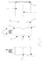
- FIG. 1 shows a bottle 1 labeled with a wrap-around label on the left hand, while the bottle 1 'shown in the center of the illustration shows the contour of the same bottle in the label-free state.
- Shown on the right hand side is a rectangular label blank 3, which is preferably provided by separating from a label tape.
- the lateral surface of the bottle 1 has an upper shell portion 2a, to which a tapered shoulder portion 2d in the direction of the bottle mouth followed. Further, the lateral surface has a lower shell portion 2b, followed by a in the direction of the bottle bottom tapered formed skirt portion 2e followed.
- the shell sections 2a and 2b may be cylindrical, ie have an extension along the axis of the bottle, or areas with a convex, convex surface with a maximum diameter.
- a radially inwardly formed portion 2c which extends in the illustrated embodiment over the entire circumference of the bottle 1 'and is concave.
- the bottle 1 'thus has a rotationally symmetrical outer contour to the bottle longitudinal axis.
- the wrap-around label 3 which consists of a shrinkable material, has a length extending from the label leading edge 3a to the label trailing edge 3b, which is greater than the maximum bottle circumference in the region of the upper and lower jacket sections 2a and 2b, so that the label trailing edge 3b after a complete Winding the label 3 on the bottle 1 'overlaps the label leading edge 3a in the circumferential direction.
- an adhesive zone 4b preferably extending over the entire label height, which may for example be in the form of a continuous hot glue strip.
- Hot glue for use, which is curable by UV irradiation.
- adhesive zones 4a which are preferably assigned to the upper and lower shell portion 2a, 2b of the bottle in terms of height on the label.
- a UV-curable hot glue can be used.
- a lower quality adhesive, in particular a conventional hot glue can be sufficient for this purpose.
- the shrinkable wrap-around label 3 has air outlet openings 5 which, in terms of height, are assigned approximately radially to the radially inward-shaped region 2c of the bottle 1 'and, for example, in the form of a perforation line running parallel to the label longitudinal edges.
- These air outlet openings may be formed as small holes or elongated slots in the label material, which are barely perceptible from the outside with the naked eye.
- the wrap-around label 3 is attached at least temporarily with the adhesive zones 4a and completely wound by subsequent rotation of the bottle 1 'about its vertical axis to overlap the front and rear edge of the label. After this winding process, the wrap-around label 3 not only covers the radially inward-shaped portion 2c but also portions of the skirt portions 2d and 2e.
- the permanent crosslinking of the adhesive takes place when using a curable hot glue, even before a shrink treatment of the label 3 for application to the bottle contour is started.
- the shrinking process is carried out by a heat treatment, for. B. by exposure to hot air, steam or infrared radiation.
- the label material contracts in the radial direction to the bottle casing surface, wherein the radially trapped region 2c between the lateral surface of the bottle and the back of the wrap-around label 3 trapped air can escape through the aforementioned air outlet openings 5 to the outside, so that a bubble-free application of the label material is ensured to the bottle contour.
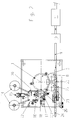
- FIG. 2 shows a schematic top view of a labeling machine which is suitable for the above-described labeling, which enables a continuously high-performance application of wrap-around labels 3 on bottles 1 'continuously fed in a single-lane series.
- the bottles have a feed conveyor 24, an inlet star wheel 25 with upstream Einteilschnecke 23, a guide arc 22, a carousel 6 with a plurality of uniformly spaced on a common pitch circle turntables 7, a discharge star wheel 8 and a discharge conveyor 9, which by a UV Tunnel 10 and a shrink tunnel 11 passes.
- the bottles are moving through the machine transport elements speed and position synchronous with each other continuously drivable.
- a labeling unit 12 for applying wrap-around labels 3 made of heat-shrinkable plastic film.
- the labeling unit 12 has two label roll receptacles 14 with an intermediate splicing station 15, a cutting unit 16, at least one gluing station 17, preferably a further gluing station 26, and a vacuum cylinder 18 for transferring a pre-cut label 3 glued to its leading and trailing edge a passing bottle 1 '.
- the labeling has a seen in the tape running direction between the splicing station 15 and the cutting unit 16 perforating 20, which consists for example of a equipped with needles perforating and a counter roll.
- the plastic film strip is fed to the cutting unit 16 by one of the two label tape rolls in a controlled strip take-off in cooperation with a print image or a marking-recognizing sensor so that a rectangular label blank having a length corresponding to the cylindrical shell circumference of the bottle 1 (with oversize) separated in the correct position to the printed image is passed to the vacuum cylinder 18, which then passes the wrap-around label 3 with the back facing outward on the glue roller of the gluing station 17 and possibly also on the glue roller of a further gluing station 26.
- the wrap-around label 3 receives in the region of its trailing edge 3b a glue application of UV-curable hot glue, which is preferably applied according to the form shown in Fig. 1, and possibly also in the leading edge 3a, but this one by the second Glue roller 26 can be applied conventional applicator glue.
- the label leading edge 3a is then brought to the lateral surfaces 2a and 2b of the bottle 1 ', adhered to the associated glue zones 4a and in the further course by a rotation of the bottle 1' caused by the turntable 7 fully wound around its vertical axis, the label trailing edge 3b after completion the rotation overlaps the label leading edge 3a and is adhered to the glue zone 4b on the outside thereof.
- the described process takes place during a continuous forward movement of the carousel 6.
- the labeled bottle 1 After passing through the labeling unit 12 and after completion of the winding process, the labeled bottle 1 reaches the outlet starwheel 8 in the further course and is transferred to the outlet conveyor 9.
- the outlet conveyor 9 transports the bottle 1 first through the UV tunnel 10, which brings about intense crosslinking and curing of the hot glue by UV irradiation, before the thermal loading of the shrinkable plastic label in the shrink tunnel 11 begins. Due to the UV treatment, the hot glue is temperature-resistant. A bursting of the fürlappungsverklebung during the shrinking treatment is reliably prevented in this way.
- the shrink treatment can be designed so that the upper and lower edge of the label before the middle label area is subjected to heat. It is possibly a local heat treatment for shrinking with appropriately positioned nozzles or heat radiators conceivable so that the voltage applied during winding of a label already on the lateral surface label areas need not be shrunk.
- the described innovation is also applicable to articles having a plurality of radially inwardly formed regions in the lateral surface.
Landscapes
- Engineering & Computer Science (AREA)
- Mechanical Engineering (AREA)
- Labeling Devices (AREA)
Abstract
Description
- Die Erfindung betrifft einen Artikel mit einer etikettierten Mantelfläche gemäß dem Oberbegriff des Anspruchs 1 bzw. 9 und eine Vorrichtung zum Etikettieren eines derartigen Artikels gemäß dem Oberbegriff des Anspruchs 10 bzw. 12.
- Ein gattungsgemäßer Artikel ist beispielsweise aus WO 95/01912 bekannt. Der dort offenbarte Artikel ist ein Behälter mit einer oberen und unteren zylindrischen Mantelfläche und einer dazwischenliegenden konkav ausgebildeten Umfangsnut. An den oberen zylindrischen Bereich der Mantelfläche schließt sich ein kegelförmig verjüngt ausgebildeter Mantelabschnitt an, der zusammen mit den zylindrischen Mantelflächen und der Nut von einem wärmeschrumpfbaren Rundumetikett mit überlappenden Endabschnitten überdeckt wird. Zur Etikettierung wird ein rechteckiger Etikettenzuschnitt, der beispielsweise von einer Etikettenrolle abgetrennt wird, im Bereich seiner Etikettenvorderkante an den zylindrischen Mantelabschnitten angeheftet, unter Ausbildung einer Überlappungsverbindung zwischen den Etikettenkanten vollständig um das Gefäß herumgewickelt und mittels einer Schrumpfbehandlung an die beschriebene Gefäßkontur angelegt. Problematisch ist dabei insbesondere die Schrumpfbehandlung, vor allem im Bereich der konkav radial einwärts geformten Nutzone.
- Demgegenüber liegt der Erfindung die Aufgabe zugrunde, eine Verbesserung der Etikettierung von Artikeln mit einem radial einwärts geformten Bereich anzugeben, insbesondere einem innerhalb einer Mantelfläche einwärts geformten Bereich.
- Gelöst wird diese Aufgabe einen Artikel betreffend durch die kennzeichnenden Merkmale des Anspruchs 1 bzw. 9 und eine Vorrichtung betreffend durch die Merkmale des Anspruchs 10 bzw. 12.
- Durch die Maßnahme, Luftaustrittsöffnungen in dem den radial einwärts geformten Bereich des Artikels überdeckenden Abschnitt des Etiketts vorzusehen, wird eine verbesserte Abfuhr der zwischen dem Etikett und dem radial einwärts geformten Bereich der Mantelfläche eingeschlossenen Luft sichergestellt, da das zwischen dem Etikett und dem genanntem Bereich der Artikeloberfläche eingeschlossene Luftvolumen durch die Luftaustrittsöffnungen problemlos radial nach außen entweichen kann, während sich das schrumpffähige Etikettenmaterial bei der Schrumpfbehandlung nach und nach an die Kontur der Artikeloberfläche anlegt. Durch diese neuerungsgemäße Maßnahme wird das Entstehen von Luftblasen unter dem Etikett wirkungsvoll vermieden.
- Um das optische Erscheinungsbild des Etiketts nicht zu beinträchtigen, können die Luftaustrittsöffnungen als eine mit bloßem Auge kaum wahrnehmbare Perforation im Etikett ausgebildet sein. Im Falle einer über den gesamten Umfang eines Artikels verlaufenden radial einwärts geformten, z. B. konkaven Nut ist eine sich ebenfalls annähernd über den gesamten Umfang des Etiketts erstreckende Perforationslinie besonders vorteilhaft, um eine gleichmäßige Luftabfuhr bei der Schrumpfbehandlung sicherzustellen. Die Perforationslinie ist bevorzugt mittig zur Nut angeordnet.
- Da nach der Schrumpfbehandlung des Etiketts eine formschlüssige Verbindung zwischen dem Etikett und dem Artikel zumindest in axialer Richtung gegeben ist, kann die Haftverbindung an der Etikettenanfangs- bzw. Etikettenvorderkante temporärer Natur sein, um lediglich während dem Aufwickelvorgang des Etiketts auf den Artikel eine Haftverbindung aufrecht zu erhalten, die nach Abschluss der Überlappungsverbindung zwischen der Etikettenanfangs- und der diese überlappenden Etikettenendkante nicht mehr weiter benötigt wird. Mit dieser optionalen Maßnahme wird auch eine Etikettenentfernung im Zusammenhang mit einem späteren Recyclingvorgang erleichtert.
- Die Überlappungsverbindung zwischen der Etikettenanfangs- und der diese überdeckenden Etikettenendkante muss dagegen von dauerhafter Qualität sein, um der nach dem Aufwickeln stattfindenden Schrumpfbehandlung, die in der Regel durch eine Erwärmung ausgelöst wird, standzuhalten.
- Hierfür ist ein durch Ultraviolettbestrahlung aushärtbarer Heißleim besonders vorteilhaft. Dieser kann ggf. auch für das Anheften der Etikettenanfangskante am Artikel verwendet werden, insbesondere wenn eine auch nach der Schrumpfbehandlung dauerhaft verdrehsichere Anbringung des Etiketts gewünscht wird. Diese Befestigungsart mit UV-aushärtbarem Heißleim an der Etikettenanfangskante und/oder Etikettenendkante ist auch bei einer Rundumetikettierung von Artikeln ohne einen radial einwärts geformten, d.h. konkaven Bereich von Vorteil, z.B. bei Flaschen, Bechern oder dgl. mit zylindrischen und/oder konvexen Mantelabschnitten (siehe US 4 923 557 oder EP 0 675 806 B1). Diese Gegenstände können beim Etikettieren starr oder nachgiebig sein, je nach Werkstoff (Glas, Metall, Kunststoff, Karton). Durch ein zweites Leimwerk kann zur Erzeugung von Klebstoffzonen im Bereich der Etikettenanfangskante ein kostengünstigerer Klebstoff aufgetragen werden, während das Aufbringen von UV-aushärtbaren Klebstoffen nahe der Etikettenendkante durch ein eigenes Leimwerk erfolgen kann.
- Weitere vorteilhafte Ausgestaltungen der Erfindung sind Gegenstand der verbleibenden Unteransprüche.
- Nachfolgend wird ein bevorzugtes Ausführungsbeispiel anhand der Figuren erläutert. Es zeigt:
- Figur 1
- einen Artikel mit einem radial einwärts geformten Bereich in seiner von einem Etikett überdeckten Mantelfläche vor und nach dem Etikettieren und
- Figur 2
- eine Vorrichtung zum Etikettieren eines Artikels gemäß Figur 1 in einer schematischen Draufsicht.
- Bei dem in Figur 1 gezeigten Ausführungsbeispiel ist der zu etikettierende Artikel eine Flasche aus Kunststoff, Glas oder Metall, die beispielsweise zur Befüllung mit Getränken, Lebensmitteln oder dgl. bestimmt ist. In Figur 1 ist eine mit einem Rundumetikett fertig etikettierte Flasche 1 linker Hand dargestellt, während die in der Mitte der Abbildung gezeigte Flasche 1' die Kontur der gleichen Flasche im noch etikettenfreien Zustand zeigt. Rechter Hand ist ein rechteckiger Etikettenzuschnitt 3 abgebildet, der bevorzugt durch Abtrennen von einem Etikettenband bereitgestellt wird.
- Die Mantelfläche der Flasche 1' besitzt einen oberen Mantelabschnitt 2a, an den sich in Richtung zur Flaschenmündung ein sich verjüngender Schulterabschnitt 2d anschließt. Ferner besitzt die Mantelfläche einen unteren Mantelabschnitt 2b, an den sich ein in Richtung zum Flaschenboden verjüngt ausgebildeter Mantelabschnitt 2e anschließt. Die Mantelabschnitte 2a und 2b können zylindrisch, d.h. eine Erstreckung längs zur Flaschenachse aufweisen, oder Bereiche mit einer balligen, konvexen Fläche mit einem maximalen Durchmesser sein.
- Zwischen dem oberen Mantelabschnitt 2a und dem unteren Mantelabschnitt 2b befindet sich ein radial einwärts geformter Bereich 2c, der sich bei dem dargestellten Ausführungsbeispiel über den gesamten Umfang der Flasche 1' erstreckt und konkav ausgebildet ist. Die Flasche 1' weist also eine zur Flaschenlängsachse rotationssymmetrische Außenkontur auf.
- Das aus einem schrumpffähigen Material bestehende Rundumetikett 3 besitzt eine sich von der Etikettenvorderkante 3a bis zur Etikettenhinterkante 3b erstreckende Länge, die größer als der maximale Flaschenumfang im Bereich des oberen und unteren Mantelabschnitts 2a bzw. 2b bemessen ist, so dass die Etikettenhinterkante 3b nach einem vollständigen Aufwickeln des Etiketts 3 auf die Flasche 1' die Etikettenvorderkante 3a in Umfangsrichtung überlappt.
- Um die Etikettenvorderkante 3a und die überlappende Etikettenhinterkante 3b dauerhaft miteinander zu verbinden, befindet sich im Bereich der Etikettenhinterkante 3b eine sich vorzugsweise über die gesamte Etikettenhöhe erstreckende Klebezone 4b, die beispielsweise in Form eines durchgehenden Heißleimstreifens ausgebildet sein kann. Bevorzugt kommt ein Heißleim zum Einsatz, der durch UV-Bestrahlung aushärtbar ist.
- Zum Aufwickeln des Rundumetiketts 3 auf die Flasche 1' befinden sich nahe an der Etikettenvorderkante 3a Klebstoffzonen 4a, die bevorzugt ausschließlich dem oberen und unteren Mantelabschnitt 2a, 2b der Flasche höhenmäßig auf dem Etikett zugeordnet sind. Auch für diesen Zweck kann ein UV-härtbarer Heißleim Verwendung finden. Aus Kostengründen kann ein qualitativ geringerwertiger Klebstoff, insbesondere ein konventioneller Heißleim hierfür ausreichen.
- Das schrumpffähige Rundumetikett 3 weist Luftaustrittsöffnungen 5 auf, die höhenmäßig dem radial einwärts geformten Bereich 2c der Flasche 1' annähernd mittig zugeordnet und beispielsweise in Form einer zu den Etikettenlängsrändern parallel verlaufenden Perforationslinie ausgebildet sind. Diese Luftaustrittsöffnungen können als kleine Löcher oder längliche Schlitze im Etikettenmaterial ausgeformt sein, die mit bloßem Auge von außen kaum wahrnehmbar sind.
- Durch tangentiales Heranführen der Etikettenvorderkante 3a an den oberen und unteren zylindrischen Mantelabschnitt 2a bzw. 2b wird das Rundumetikett 3 mit den Klebstoffzonen 4a zumindest temporär angeheftet und durch nachfolgendes Drehen der Flasche 1' um ihre Hochachse vollständig bis zum Überlappen der vorderen und hinteren Etikettenkante aufgewickelt. Nach diesem Aufwickelvorgang überdeckt das Rundumetikett 3 nicht nur den radial einwärts geformten Bereich 2c, sondern auch Teile der Mantelbereiche 2d und 2e.
- Durch eine Beaufschlagung der Klebezone 4b im Überlappungsbereich mit UV-Strahlen erfolgt bei verwendung eines härtbaren Heißleims die dauerhafte Vernetzung des Klebstoffs, noch bevor eine Schrumpfbehandlung des Etiketts 3 zur Anlegung an die Flaschenkontur gestartet wird.
- Bei Etiketten aus einem thermoplastischen Kunststofffolienmaterial erfolgt der Schrumpfvorgang durch eine Wärmebehandlung, z. B. durch Beaufschlagung mit Heißluft, Dampf oder Infrarotstrahlung. Dabei zieht sich das Etikettenmaterial in radialer Richtung zur Flaschenmantelfläche zusammen, wobei die im radial eingezogenen Bereich 2c zwischen der Mantelfläche der Flasche und der Rückseite des Rundumetiketts 3 eingeschlossene Luft durch die zuvor erwähnten Luftaustrittsöffnungen 5 nach außen entweichen kann, so dass ein blasenfreies Anlegen des Etikettenmaterials an die Flaschenkontur sichergestellt ist.
- In Figur 2 ist eine für die vorhergehend beschriebene Etikettierung geeignete Etikettiermaschine in einer schematischen Draufsicht erkennbar, die eine kontinuierlich mit hoher Leistung erfolgende Aufbringung von Rundumetiketten 3 auf in einer einspurigen Reihe fortlaufend zugeführte Flaschen 1' ermöglicht.
- Sie verfügt über einen Zulaufförderer 24, ein Einlaufsternrad 25 mit vorgeordneter Einteilschnecke 23, einen Führungsbogen 22, ein Karussell 6 mit einer Vielzahl von in gleichmäßigen Abständen auf einem gemeinsamen Teilkreis angeordneten Drehtellern 7, ein Auslaufsternrad 8 und einen Auslaufförderer 9, der durch einen UV-Tunnel 10 und einen Schrumpftunnel 11 hindurchführt. Die genannten, die Flaschen durch die Maschine bewegenden Transportelemente sind geschwindigkeits- und stellungssynchron zueinander kontinuierlich antreibbar.
- Im Umlaufbereich zwischen dem Einlaufsternrad 25 und dem Auslaufsternrad 8 befindet sich an der äußeren Peripherie des Karussells 6 ein Etikettieraggregat 12 zum Aufbringen von Rundumetiketten 3 aus wärmeschrumpfbarer Kunststofffolie. Das Etikettieraggregat 12 verfügt über zwei Etikettenrollenaufnahmen 14 mit einer dazwischen liegenden Anspleißstation 15, ein Schneidwerk 16, wenigstens eine Beleimungsstation 17, vorzugsweise eine weitere Beleimungsstation 26, und einen Vakuumzylinder 18 zum Übertragen eines vorgeschnittenen, an seiner vor- und nachlaufenden Kante beleimten Etiketts 3 auf eine vorbeilaufende Flasche 1'. Wird ein Etikettenfolienband verarbeitet, das nicht vorab bereits mit Luftdurchtrittsöffnungen 5 versehen ist, verfügt das Etikettieraggregat über eine in Bandlaufrichtung gesehen zwischen der Anspleißstation 15 und dem Schneidwerk 16 angeordnete Perforationseinrichtung 20, die beispielsweise aus einer mit Nadeln bestückten Perforationswalze und einer Gegenwalze besteht.
- Der Etikettiervorgang einer Flasche 1' läuft im Einzelnen wie folgt ab:
- Eine vom Zulaufförderer 24 herangeführte Flasche 1' wird in Verbindung mit der seitlich angeordneten Einteilschnecke 23 stellungsgerecht in das Einlaufsternrad 5 eingeführt und von diesem in Zusammenarbeit mit dem gegenüberliegenden Führungsbogen 22 in kontinuierlicher Bewegung auf einen Drehteller 7 des rotierenden Karussells 6 übergeschoben. Dort wird die Flasche 1' von einer nicht dargestellten, relativ zum Drehteller 7 gesteuert heb- und senkbaren Zentrierglocke axial auf dem Drehteller mit diesem drehbar eingespannt und durch die Umlaufbewegung des Karussells tangential an den Vakuumzylinder 18 des Etikettieraggregats 12 herangeführt.
- Dazu zeitlich parallel verlaufend wird von einer der beiden Etikettenbandrollen das Kunststofffolienband einem gesteuerten Bandabzug im Zusammenwirken mit einem Druckbild oder einer Markierung erkennenden Sensor dem Schneidwerk 16 so zugeführt, dass ein rechteckiger Etikettenzuschnitt mit einer dem zylindrischen Mantelumfang der Flasche 1' entsprechenden Länge (mit Übermaß) lagerichtig zum Druckbild abgetrennt an den Vakuumzylinder 18 übergeben wird, der das Rundumetikett 3 dann mit der Rückseite nach außen weisend an der Leimwalze der Beleimungsstation 17 und ggf. noch an der Leimwalze einer weiteren Beleimungsstation 26 vorbeiführt. Das Rundumetikett 3 erhält dabei im Bereich seiner nachlaufenden Kante 3b einen Leimauftrag aus UV-härtbaren Heißleim, der bevorzugt entsprechend der in Fig. 1 dargestellten Form aufgebracht wird, und ggf. auch im Bereich der vorlaufenden Kante 3a, wobei hierfür allerdings ein durch die zweite Leimwalze 26 auftragbarer konventioneller Leim genügen kann.
- Die Etikettenvorderkante 3a wird dann an die Mantelflächen 2a und 2b der Flasche 1' herangeführt, mit den zugeordneten Leimzonen 4a angeheftet und im weiteren Verlauf durch eine vom Drehteller 7 veranlasste Drehung der Flasche 1' um ihre Hochachse vollumfänglich aufgewickelt, wobei die Etikettenhinterkante 3b nach Abschluss der Drehung die Etikettenvorderkante 3a überlappt und mit der Leimzone 4b an deren Außenseite angeheftet wird. Der geschilderte Vorgang erfolgt während einer kontinuierlichen Vorwärtsbewegung des Karussells 6.
- Nach dem Passieren des Etikettieraggregats 12 und nach Abschluss des Aufwickelvorgangs erreicht die etikettierte Flasche 1 im weiteren Verlauf das Auslaufsternrad 8 und wird an den Auslaufförderer 9 übergeben.
- Der Auslaufförderer 9 transportiert die Flasche 1 zuerst durch den UV-Tunnel 10, der durch UV-Bestrahlung eine intensive Vernetzung und Aushärtung des Heißleims herbeiführt, noch bevor die thermische Beaufschlagung des schrumpffähigen Kunststoffetiketts im Schrumpftunnel 11 einsetzt. Durch die genannte UV-Behandlung ist der Heißleim temperaturbelastbar. Ein Aufplatzen der Überlappungsverklebung während der Schrumpfbehandlung wird auf diese Weise zuverlässig verhindert. Die Schrumpfbehandlung kann so gestaltet sein, dass der obere und untere Etikettenrand vor dem mittleren Etikettenbereich mit wärme beaufschlagt wird. Es ist ggf. eine lokale Wärmebehandlung zum Schrumpfen mit entsprechend positionierten Blasdüsen oder Wärmestrahlern denkbar, so dass die beim Aufwickeln eines Etiketts bereits an der Mantelfläche anliegenden Etikettenbereiche nicht mehr geschrumpft werden brauchen.
- Natürlich ist die beschriebene Neuerung auch auf Artikel mit mehreren radial einwärts geformten Bereichen in der Mantelfläche anwendbar.
Claims (14)
- Artikel (1) mit einer etikettierten Mantelfläche, die einen oberen und unteren zylindrischen und/oder konvexen Mantelabschnitt (2a, 2b) und wenigstens einen dazwischenliegenden, radial einwärts geformten, von einem schrumpffähigen Etikett (3) überdeckten Bereich (2c) aufweist, dadurch gekennzeichnet, dass das Etikett (3) wenigstens dem radial einwärts geformten Bereich (2c) zugeordnete Luftaustrittsöffnungen (5) aufweist.
- Artikel nach Anspruch 1, dadurch gekennzeichnet, dass die Luftaustrittsöffnungen (5) als Perforation im Etikettenmaterial ausgebildet sind.
- Artikel nach Anspruch 1 oder 2, dadurch gekennzeichnet, dass der radial einwärts geformte Bereich (2c) der Mantelfläche vollumfänglich verlaufend ausgebildet ist.
- Artikel nach Anspruch 2 und 3, dadurch gekennzeichnet, dass die Luftaustrittsöffnungen (5) als wenigstens eine vollumfänglich verlaufende Perforationslinie ausgebildet sind.
- Artikel nach wenigsten einem der vorhergehenden Ansprüche, dadurch gekennzeichnet, dass das Etikett (3) ein Rundumetikett mit überlappender Anfangs- und Endkante (3a, 3b) ist.
- Artikel nach Anspruch 5, dadurch gekennzeichnet, dass das Etikett (3) im Bereich seiner Anfangskante (3a) mit einem Haftmittel (4a), vorzugsweise Heißleim, zumindest temporär mit der Mantelfläche (2a, 2b), des Artikels verbunden ist.
- Artikel nach Anspruch 5 oder 6, dadurch gekennzeichnet, dass das Etikett (3) zumindest im Bereich seiner überlappenden Endkante (3b) dauerhaft mit der Anfangskante (3a) verbunden ist, vorzugsweise durch einen UV-aushärtbaren Heißleim (4b).
- Artikel nach wenigstens einem der vorhergehenden Ansprüche 1 bis 7, dadurch gekennzeichnet, dass die Mantelfläche wenigstens ober- und/oder unterhalb des radial einwärts geformten Bereichs (2c) einen sich verjüngenden Bereich (2d, 2e) aufweist, der vom Etikett (3) zumindest teilweise überdeckt wird.
- Artikel (1) mit einer mit einem insbesondere wärmeschrumpfbaren Rundumetikett (3) etikettierten Mantelfläche, dadurch gekennzeichnet, dass das Etikett (3) nahe seiner Anfangskante und/oder Endkante (3b) eine Zone W-aushärtbaren Heißleims (4b, 4a) aufweist, wobei die Etikettenlänge vorzugsweise so bemessen ist, dass die Endkante die Anfangskante überlappt und mit dieser verbunden ist.
- Vorrichtung zum Etikettieren eines Artikels nach dem Oberbegriff des Anspruchs 1, insbesondere entsprechend wenigstens einem der vorhergehenden Ansprüche 1 bis 8, dadurch gekennzeichnet, dass die Vorrichtung Mittel (20) zum Einbringen von Luftaustrittsöffnungen (5) in ein Etikett (3) aufweist.
- Vorrichtung nach Anspruch 10, dadurch gekennzeichnet, dass die Mittel ein Perforationswerkzeug (20) umfassen, das im Förderweg der Etiketten (3) angeordnet ist, insbesondere in Höhe des dem radial einwärts geformten Bereichs (2c) der Mantelfläche des Artikels zugeordneten Abschnitts der Etiketten.
- Vorrichtung zum Etikettieren eines Artikels nach dem Oberbegriff des Anspruchs 1 oder 9, dadurch gekennzeichnet, dass sie wenigstens eine Beleimungsstation (17) zum Bilden von Klebstoffzonen (4a, 4b) mit UV-aushärtbarem Heißleim nahe der Etikettenanfangs- und/oder Etikettenendkante eines Etiketts (3) und eine Einrichtung (10) zur Beaufschlagung eines Artikels nach dem Aufbringen eines Etiketts mit UV-Strahlung aufweist.
- Vorrichtung nach Anspruch 12, dadurch gekennzeichnet, dass sie einen umlaufend antreibbaren Vakuumzylinder (18) aufweist, an dessen Peripherie die wenigstens eine Beleimungsstation (17) angeordnet ist, und der die Etiketten (3) zur Bildung der Klebstoffzonen (4a, 4b) an der Beleimungsstation vorbeiführt.
- Vorrichtung nach Anspruch 12 oder 13, dadurch gekennzeichnet, dass wenigstens zwei Beleimungsstationen (17, 26) vorgesehen sind, wobei eine Beleimungsstation (17) zum Bilden von Klebstoffzonen (4b) mit UV-aushärtbarem Heißleim nahe der Etikettenendkante (3b) und die wenigstens zweite Beleimungsstation (26) zum Bilden von Klebstoffzonen (4a) mit einem anderen Klebstoff, insbesondere einem konventionellen Heißleim, nahe der Etikettenanfangskante (3a) vorgesehen ist.
Applications Claiming Priority (1)
| Application Number | Priority Date | Filing Date | Title |
|---|---|---|---|
| DE202004013947U DE202004013947U1 (de) | 2004-09-08 | 2004-09-08 | Artikel mit einer etikettierten Mantelfläche und Vorrichtung zum Etikettieren eines Artikels |
Publications (3)
| Publication Number | Publication Date |
|---|---|
| EP1634817A2 true EP1634817A2 (de) | 2006-03-15 |
| EP1634817A3 EP1634817A3 (de) | 2006-09-13 |
| EP1634817B1 EP1634817B1 (de) | 2008-10-29 |
Family
ID=34202625
Family Applications (1)
| Application Number | Title | Priority Date | Filing Date |
|---|---|---|---|
| EP05019595A Expired - Lifetime EP1634817B1 (de) | 2004-09-08 | 2005-09-08 | Artikel mit einer etikettierten Mantelfläche und Vorrichtung zum Etikettieren eines Artikels |
Country Status (4)
| Country | Link |
|---|---|
| US (1) | US20060048417A1 (de) |
| EP (1) | EP1634817B1 (de) |
| AT (1) | ATE412581T1 (de) |
| DE (2) | DE202004013947U1 (de) |
Cited By (5)
| Publication number | Priority date | Publication date | Assignee | Title |
|---|---|---|---|---|
| DE102007014870A1 (de) * | 2007-03-26 | 2008-10-02 | Khs Ag | Verfahren zum Herstellen von Flaschen oder dergleichen Behälter aus Kunststoff |
| EP2186734A1 (de) | 2008-11-14 | 2010-05-19 | Krones AG | Schrumpffähiges Etikett sowie Verfahren und Vorrichtung zum Etikettieren von Behältnissen |
| EP2287080A2 (de) | 2009-08-21 | 2011-02-23 | Krones AG | Einrichtung und Verfahren zum Etikettieren von Behältern mit unterschiedlichen Etikettentypen |
| EP2394918A1 (de) | 2010-06-08 | 2011-12-14 | Henkel AG & Co. KGaA | Verfahren zum Verkleben von UV-härtbaren Klebstoffen |
| DE102018209902A1 (de) | 2018-06-19 | 2019-12-19 | Krones Aktiengesellschaft | Verfahren zur Etikettierung von Leerflaschen aus Kunststoff und Etikettiermaschine |
Families Citing this family (14)
| Publication number | Priority date | Publication date | Assignee | Title |
|---|---|---|---|---|
| WO2007015245A2 (en) * | 2005-08-04 | 2007-02-08 | Polysack Plastic Industries Ltd | Thermoplastic shrinkable polymeric film |
| EP1955952B1 (de) | 2007-02-06 | 2016-05-04 | Krones Ag | Vorrichtung zum Ausstatten von Gegenständen mit einem Rundumetikett |
| US8282754B2 (en) * | 2007-04-05 | 2012-10-09 | Avery Dennison Corporation | Pressure sensitive shrink label |
| DE102009031479A1 (de) * | 2009-07-01 | 2011-01-05 | Krones Ag | Vorrichtung zum Anbringen von Etikettenstreifen an Behältnissen |
| DE102009035269A1 (de) * | 2009-07-29 | 2011-02-03 | Krones Ag | Schneideinrichtung und Schneidverfahren zum Schneiden von Etiketten sowie Etikettiervorrichtung |
| WO2011094117A2 (en) | 2010-01-28 | 2011-08-04 | Avery Dennison Corporation | Label applicator belt system |
| JP5672089B2 (ja) * | 2011-03-15 | 2015-02-18 | オムロン株式会社 | 表示シートを備える機器の組立方法および表示シートを備える機器 |
| JP2014019492A (ja) * | 2012-07-23 | 2014-02-03 | Fuji Seal International Inc | ラベル付き容器 |
| JP5974287B2 (ja) * | 2012-08-22 | 2016-08-23 | 株式会社フジシール | シュリンクラベル付き容器及びシュリンクラベル |
| CN105473457A (zh) * | 2013-05-06 | 2016-04-06 | 达能日尔维公司 | 饮料瓶、制造饮料瓶的方法和设计插图的方法 |
| PL411535A1 (pl) * | 2015-03-10 | 2016-09-12 | Aleuro Converting Trade Spółka Z Ograniczoną Odpowiedzialnością | Sposób etykietowania rulonu folii spożywczej, urządzenie perforacyjne maszyny etykietującej oraz etykieta rulonu folii spożywczej |
| DE102015204821A1 (de) * | 2015-03-17 | 2016-09-22 | Krones Aktiengesellschaft | Vorrichtung und Verfahren zum Perforieren eines Folienschlauchs |
| JP2018120082A (ja) * | 2017-01-25 | 2018-08-02 | 株式会社トービ | シュリンクラベルおよびその製造方法 |
| CN109353628B (zh) * | 2018-12-11 | 2024-05-14 | 常熟利星光电科技有限公司 | 一种电源线双标签同步贴标装置 |
Citations (3)
| Publication number | Priority date | Publication date | Assignee | Title |
|---|---|---|---|---|
| US4923557A (en) | 1988-08-01 | 1990-05-08 | Trine Manufacturing Co., Inc. | Apparatus and method for applying a heat shrink film to a container |
| WO1995001912A1 (en) | 1993-07-09 | 1995-01-19 | B & H Manufacturing Co., Inc. | Labeling containers having deep grooves |
| EP0675806B1 (de) | 1992-12-18 | 2001-02-28 | B & H MANUFACTURING COMPANY, INC. | Verfahren zum etikettieren von gegenständen mit konvexen oberflächen |
Family Cites Families (14)
| Publication number | Priority date | Publication date | Assignee | Title |
|---|---|---|---|---|
| US4704173A (en) * | 1982-05-27 | 1987-11-03 | Wolfgang Hoffman | System for applying heat shrink film to containers and other articles and heat shrinking the same |
| US4574020A (en) * | 1983-11-28 | 1986-03-04 | Owens-Illinois, Inc. | Apparatus and method for wrapping a plastic label around a container |
| US4844760A (en) * | 1986-09-23 | 1989-07-04 | Trine Manufacturing Co., Inc. | Apparatus and method for applying |
| US4976798A (en) * | 1990-01-12 | 1990-12-11 | Shibuya America Corporation | Method of applying a plastic wrap to a contoured container |
| US5639529A (en) * | 1993-02-02 | 1997-06-17 | Moore Business Forms, Inc. | Permanent placed, easy removable label, for bottles and cans |
| ATE264225T1 (de) * | 1995-06-07 | 2004-04-15 | B & H Mfg Co Inc | Verfahren und vorrichtung zum anbringen von etiketten in blindenschrift auf gegenständen |
| BR9609498A (pt) * | 1995-06-28 | 1999-05-25 | B & H Mfg Co Inc | Processo para aplicar um segmento elástico de material em folha à superfície de um artigo e artigo enrolado por um segmento elástico de material em folha |
| US5897722A (en) * | 1996-07-12 | 1999-04-27 | B & H Manufacturing Company, Inc. | Process for applying labels with delayed adhesive activation |
| DE19750429A1 (de) * | 1997-11-14 | 1999-05-20 | Gerro Plast Gmbh | Verfahren zum Aufbringen einer schrumpfartigen Hülse aus folienartigem Schaumstoff auf eine Flasche oder dergleichen und Flasche oder dergleichen mit einer solchen Hülse |
| CA2327790C (en) * | 1998-04-09 | 2007-07-17 | Asahi Breweries, Ltd. | Full-shrink labeled container and tubular shrink label |
| DE19859063A1 (de) * | 1998-12-22 | 2000-06-29 | Frank Berrenbaum | Dekoratives Rundumetikett für Getränkeflaschen |
| US6649259B1 (en) * | 2000-02-29 | 2003-11-18 | National Starch And Chemical Investment Holding Corporation | Adhesives for thermally shrinkable films or labels |
| US6486229B1 (en) * | 2000-03-02 | 2002-11-26 | National Starch And Chemical Investment Holding Corporation | Radiation curable hot melt adhesive |
| JP4243085B2 (ja) * | 2002-10-07 | 2009-03-25 | 株式会社フジシールインターナショナル | 切取り線付き熱収縮性フィルム、その切取り線形成方法及び連続フィルム体 |
-
2004
- 2004-09-08 DE DE202004013947U patent/DE202004013947U1/de not_active Expired - Lifetime
-
2005
- 2005-08-18 US US11/207,397 patent/US20060048417A1/en not_active Abandoned
- 2005-09-08 DE DE502005005789T patent/DE502005005789D1/de not_active Expired - Lifetime
- 2005-09-08 EP EP05019595A patent/EP1634817B1/de not_active Expired - Lifetime
- 2005-09-08 AT AT05019595T patent/ATE412581T1/de not_active IP Right Cessation
Patent Citations (3)
| Publication number | Priority date | Publication date | Assignee | Title |
|---|---|---|---|---|
| US4923557A (en) | 1988-08-01 | 1990-05-08 | Trine Manufacturing Co., Inc. | Apparatus and method for applying a heat shrink film to a container |
| EP0675806B1 (de) | 1992-12-18 | 2001-02-28 | B & H MANUFACTURING COMPANY, INC. | Verfahren zum etikettieren von gegenständen mit konvexen oberflächen |
| WO1995001912A1 (en) | 1993-07-09 | 1995-01-19 | B & H Manufacturing Co., Inc. | Labeling containers having deep grooves |
Cited By (8)
| Publication number | Priority date | Publication date | Assignee | Title |
|---|---|---|---|---|
| DE102007014870A1 (de) * | 2007-03-26 | 2008-10-02 | Khs Ag | Verfahren zum Herstellen von Flaschen oder dergleichen Behälter aus Kunststoff |
| EP2186734A1 (de) | 2008-11-14 | 2010-05-19 | Krones AG | Schrumpffähiges Etikett sowie Verfahren und Vorrichtung zum Etikettieren von Behältnissen |
| EP2287080A2 (de) | 2009-08-21 | 2011-02-23 | Krones AG | Einrichtung und Verfahren zum Etikettieren von Behältern mit unterschiedlichen Etikettentypen |
| DE102009043880A1 (de) | 2009-08-21 | 2011-02-24 | Krones Ag | Einrichtung und Verfahren zum Etikettieren von Behältern mit unterschiedlichen Etikettentypen |
| US8627870B2 (en) | 2009-08-21 | 2014-01-14 | Krones Ag | Apparatus and method for labeling containers with different types of labels |
| EP2394918A1 (de) | 2010-06-08 | 2011-12-14 | Henkel AG & Co. KGaA | Verfahren zum Verkleben von UV-härtbaren Klebstoffen |
| DE102018209902A1 (de) | 2018-06-19 | 2019-12-19 | Krones Aktiengesellschaft | Verfahren zur Etikettierung von Leerflaschen aus Kunststoff und Etikettiermaschine |
| EP3584184A1 (de) | 2018-06-19 | 2019-12-25 | Krones AG | Verfahren zur etikettierung von leerflaschen aus kunststoff und etikettiermaschine |
Also Published As
| Publication number | Publication date |
|---|---|
| DE502005005789D1 (de) | 2008-12-11 |
| ATE412581T1 (de) | 2008-11-15 |
| EP1634817A3 (de) | 2006-09-13 |
| US20060048417A1 (en) | 2006-03-09 |
| EP1634817B1 (de) | 2008-10-29 |
| DE202004013947U1 (de) | 2005-02-17 |
Similar Documents
| Publication | Publication Date | Title |
|---|---|---|
| EP1634817B1 (de) | Artikel mit einer etikettierten Mantelfläche und Vorrichtung zum Etikettieren eines Artikels | |
| EP2287080B1 (de) | Einrichtung und Verfahren zum Etikettieren von Behältern mit unterschiedlichen Etikettentypen | |
| EP2785596B1 (de) | Vorrichtung zur bildung von verpackungseinheiten | |
| EP0525729B1 (de) | Verfahren und Vorrichtung zum Ausstatten von Gefässen mit einem Etikett aus siegelfähigem Material und derart ausgestattete Gefässe | |
| DE69329976T3 (de) | Verfahren zum etikettieren von gegenständen mit konvexen oberflächen | |
| DE3442995C2 (de) | ||
| DE102011106759B3 (de) | Verfahren zur Herstellung von Gebinden | |
| EP0559005B1 (de) | Verfahren und Vorrichtung zum Aufbringen eines Rundumetiketts auf einen Behälter | |
| DE3123637C2 (de) | Vorrichtung zur Aufbringung von Kunststoffhüllen auf Behälter | |
| DE19630690A1 (de) | Flasche o. dgl. mit einem den Umfang umschließenden Etikett, Verfahren und Vorrichtung zur Erzeugung dieser Flasche | |
| DE69100355T2 (de) | Verfahren und Vorrichtung zur Heisssiegelung von Etiketten auf Behältern. | |
| EP2801535B1 (de) | Vorrichtung zum Etikettieren von Behältern und zum Anbringen von Schrumpfhülsen auf Behältern und Verfahren dazu | |
| DE68905233T2 (de) | Maschine mit verlängerten Spannfuttern zum Anbringen von Schrumpfetiketten. | |
| WO2013004340A1 (de) | Verfahren zur herstellung von gebinden aus behältern | |
| DE3637465A1 (de) | Verfahren und vorrichtung zur aufbringung eines kunststoffetikettes auf einen behaelter | |
| WO2013113464A1 (de) | Ovale behälterbehandlungsvorrichtung | |
| DE3637466A1 (de) | Verfahren und vorrichtung zur aufbringung eines loesungsmittels auf kunststoffetiketten | |
| DE69712040T2 (de) | Verfahren und vorrichtung zum etikettieren von behältern | |
| EP3099580B1 (de) | Verfahren und vorrichtung zur bildung von verpackungseinheiten | |
| DE69808319T2 (de) | Verfahren und vorrichtung zur etikettierung von behältern mit durch pressluft unterstütztem transfer der etiketten | |
| DE69623624T2 (de) | Verfahren zum aufbringen von dehnbaren etiketten | |
| DE102004047595A1 (de) | Verfahren und Vorrichtung zum Ausstatten von Gefäßen | |
| EP2186734B1 (de) | Schrumpffähiges Etikett sowie Verfahren und Vorrichtung zum Etikettieren von Behältnissen | |
| DE69409822T2 (de) | Vorrichtung und verfahren zum etikettieren von behältern unter verwendung heissverschweissbarer etiketten | |
| DE19531839A1 (de) | Verfahren und Vorrichtung zum Ausstatten von Gegenständen |
Legal Events
| Date | Code | Title | Description |
|---|---|---|---|
| PUAI | Public reference made under article 153(3) epc to a published international application that has entered the european phase |
Free format text: ORIGINAL CODE: 0009012 |
|
| AK | Designated contracting states |
Kind code of ref document: A2 Designated state(s): AT BE BG CH CY CZ DE DK EE ES FI FR GB GR HU IE IS IT LI LT LU LV MC NL PL PT RO SE SI SK TR |
|
| AX | Request for extension of the european patent |
Extension state: AL BA HR MK YU |
|
| 17P | Request for examination filed |
Effective date: 20060315 |
|
| PUAL | Search report despatched |
Free format text: ORIGINAL CODE: 0009013 |
|
| AK | Designated contracting states |
Kind code of ref document: A3 Designated state(s): AT BE BG CH CY CZ DE DK EE ES FI FR GB GR HU IE IS IT LI LT LU LV MC NL PL PT RO SE SI SK TR |
|
| AX | Request for extension of the european patent |
Extension state: AL BA HR MK YU |
|
| 17Q | First examination report despatched |
Effective date: 20061108 |
|
| AKX | Designation fees paid |
Designated state(s): AT BE BG CH CY CZ DE DK EE ES FI FR GB GR HU IE IS IT LI LT LU LV MC NL PL PT RO SE SI SK TR |
|
| GRAP | Despatch of communication of intention to grant a patent |
Free format text: ORIGINAL CODE: EPIDOSNIGR1 |
|
| GRAS | Grant fee paid |
Free format text: ORIGINAL CODE: EPIDOSNIGR3 |
|
| GRAA | (expected) grant |
Free format text: ORIGINAL CODE: 0009210 |
|
| AK | Designated contracting states |
Kind code of ref document: B1 Designated state(s): AT BE BG CH CY CZ DE DK EE ES FI FR GB GR HU IE IS IT LI LT LU LV MC NL PL PT RO SE SI SK TR |
|
| REG | Reference to a national code |
Ref country code: GB Ref legal event code: FG4D Free format text: NOT ENGLISH |
|
| REG | Reference to a national code |
Ref country code: CH Ref legal event code: EP |
|
| REG | Reference to a national code |
Ref country code: IE Ref legal event code: FG4D Free format text: LANGUAGE OF EP DOCUMENT: GERMAN |
|
| REF | Corresponds to: |
Ref document number: 502005005789 Country of ref document: DE Date of ref document: 20081211 Kind code of ref document: P |
|
| NLV1 | Nl: lapsed or annulled due to failure to fulfill the requirements of art. 29p and 29m of the patents act | ||
| LTIE | Lt: invalidation of european patent or patent extension |
Effective date: 20081029 |
|
| PG25 | Lapsed in a contracting state [announced via postgrant information from national office to epo] |
Ref country code: ES Free format text: LAPSE BECAUSE OF FAILURE TO SUBMIT A TRANSLATION OF THE DESCRIPTION OR TO PAY THE FEE WITHIN THE PRESCRIBED TIME-LIMIT Effective date: 20090209 Ref country code: BG Free format text: LAPSE BECAUSE OF FAILURE TO SUBMIT A TRANSLATION OF THE DESCRIPTION OR TO PAY THE FEE WITHIN THE PRESCRIBED TIME-LIMIT Effective date: 20090129 Ref country code: LT Free format text: LAPSE BECAUSE OF FAILURE TO SUBMIT A TRANSLATION OF THE DESCRIPTION OR TO PAY THE FEE WITHIN THE PRESCRIBED TIME-LIMIT Effective date: 20081029 |
|
| PG25 | Lapsed in a contracting state [announced via postgrant information from national office to epo] |
Ref country code: IS Free format text: LAPSE BECAUSE OF FAILURE TO SUBMIT A TRANSLATION OF THE DESCRIPTION OR TO PAY THE FEE WITHIN THE PRESCRIBED TIME-LIMIT Effective date: 20090228 Ref country code: LV Free format text: LAPSE BECAUSE OF FAILURE TO SUBMIT A TRANSLATION OF THE DESCRIPTION OR TO PAY THE FEE WITHIN THE PRESCRIBED TIME-LIMIT Effective date: 20081029 Ref country code: PL Free format text: LAPSE BECAUSE OF FAILURE TO SUBMIT A TRANSLATION OF THE DESCRIPTION OR TO PAY THE FEE WITHIN THE PRESCRIBED TIME-LIMIT Effective date: 20081029 Ref country code: PT Free format text: LAPSE BECAUSE OF FAILURE TO SUBMIT A TRANSLATION OF THE DESCRIPTION OR TO PAY THE FEE WITHIN THE PRESCRIBED TIME-LIMIT Effective date: 20090330 Ref country code: NL Free format text: LAPSE BECAUSE OF FAILURE TO SUBMIT A TRANSLATION OF THE DESCRIPTION OR TO PAY THE FEE WITHIN THE PRESCRIBED TIME-LIMIT Effective date: 20081029 Ref country code: SI Free format text: LAPSE BECAUSE OF FAILURE TO SUBMIT A TRANSLATION OF THE DESCRIPTION OR TO PAY THE FEE WITHIN THE PRESCRIBED TIME-LIMIT Effective date: 20081029 Ref country code: FI Free format text: LAPSE BECAUSE OF FAILURE TO SUBMIT A TRANSLATION OF THE DESCRIPTION OR TO PAY THE FEE WITHIN THE PRESCRIBED TIME-LIMIT Effective date: 20081029 |
|
| REG | Reference to a national code |
Ref country code: IE Ref legal event code: FD4D |
|
| PG25 | Lapsed in a contracting state [announced via postgrant information from national office to epo] |
Ref country code: DK Free format text: LAPSE BECAUSE OF FAILURE TO SUBMIT A TRANSLATION OF THE DESCRIPTION OR TO PAY THE FEE WITHIN THE PRESCRIBED TIME-LIMIT Effective date: 20081029 Ref country code: RO Free format text: LAPSE BECAUSE OF FAILURE TO SUBMIT A TRANSLATION OF THE DESCRIPTION OR TO PAY THE FEE WITHIN THE PRESCRIBED TIME-LIMIT Effective date: 20081029 Ref country code: EE Free format text: LAPSE BECAUSE OF FAILURE TO SUBMIT A TRANSLATION OF THE DESCRIPTION OR TO PAY THE FEE WITHIN THE PRESCRIBED TIME-LIMIT Effective date: 20081029 Ref country code: IE Free format text: LAPSE BECAUSE OF FAILURE TO SUBMIT A TRANSLATION OF THE DESCRIPTION OR TO PAY THE FEE WITHIN THE PRESCRIBED TIME-LIMIT Effective date: 20081029 |
|
| PLBI | Opposition filed |
Free format text: ORIGINAL CODE: 0009260 |
|
| PLAB | Opposition data, opponent's data or that of the opponent's representative modified |
Free format text: ORIGINAL CODE: 0009299OPPO |
|
| PG25 | Lapsed in a contracting state [announced via postgrant information from national office to epo] |
Ref country code: SE Free format text: LAPSE BECAUSE OF FAILURE TO SUBMIT A TRANSLATION OF THE DESCRIPTION OR TO PAY THE FEE WITHIN THE PRESCRIBED TIME-LIMIT Effective date: 20090129 Ref country code: CZ Free format text: LAPSE BECAUSE OF FAILURE TO SUBMIT A TRANSLATION OF THE DESCRIPTION OR TO PAY THE FEE WITHIN THE PRESCRIBED TIME-LIMIT Effective date: 20081029 |
|
| 26 | Opposition filed |
Opponent name: KHS AG Effective date: 20090729 |
|
| PLAX | Notice of opposition and request to file observation + time limit sent |
Free format text: ORIGINAL CODE: EPIDOSNOBS2 |
|
| R26 | Opposition filed (corrected) |
Opponent name: KHS AG Effective date: 20090729 |
|
| PG25 | Lapsed in a contracting state [announced via postgrant information from national office to epo] |
Ref country code: SK Free format text: LAPSE BECAUSE OF FAILURE TO SUBMIT A TRANSLATION OF THE DESCRIPTION OR TO PAY THE FEE WITHIN THE PRESCRIBED TIME-LIMIT Effective date: 20081029 |
|
| PLBB | Reply of patent proprietor to notice(s) of opposition received |
Free format text: ORIGINAL CODE: EPIDOSNOBS3 |
|
| BERE | Be: lapsed |
Owner name: KRONES A.G. Effective date: 20090930 |
|
| PG25 | Lapsed in a contracting state [announced via postgrant information from national office to epo] |
Ref country code: MC Free format text: LAPSE BECAUSE OF NON-PAYMENT OF DUE FEES Effective date: 20090930 |
|
| REG | Reference to a national code |
Ref country code: CH Ref legal event code: PL |
|
| GBPC | Gb: european patent ceased through non-payment of renewal fee |
Effective date: 20090908 |
|
| REG | Reference to a national code |
Ref country code: FR Ref legal event code: ST Effective date: 20100531 |
|
| PG25 | Lapsed in a contracting state [announced via postgrant information from national office to epo] |
Ref country code: FR Free format text: LAPSE BECAUSE OF NON-PAYMENT OF DUE FEES Effective date: 20090930 |
|
| PG25 | Lapsed in a contracting state [announced via postgrant information from national office to epo] |
Ref country code: BE Free format text: LAPSE BECAUSE OF NON-PAYMENT OF DUE FEES Effective date: 20090930 |
|
| PG25 | Lapsed in a contracting state [announced via postgrant information from national office to epo] |
Ref country code: LI Free format text: LAPSE BECAUSE OF NON-PAYMENT OF DUE FEES Effective date: 20090930 Ref country code: GR Free format text: LAPSE BECAUSE OF FAILURE TO SUBMIT A TRANSLATION OF THE DESCRIPTION OR TO PAY THE FEE WITHIN THE PRESCRIBED TIME-LIMIT Effective date: 20090130 Ref country code: CH Free format text: LAPSE BECAUSE OF NON-PAYMENT OF DUE FEES Effective date: 20090930 |
|
| PG25 | Lapsed in a contracting state [announced via postgrant information from national office to epo] |
Ref country code: AT Free format text: LAPSE BECAUSE OF NON-PAYMENT OF DUE FEES Effective date: 20090908 Ref country code: GB Free format text: LAPSE BECAUSE OF NON-PAYMENT OF DUE FEES Effective date: 20090908 |
|
| PG25 | Lapsed in a contracting state [announced via postgrant information from national office to epo] |
Ref country code: LU Free format text: LAPSE BECAUSE OF NON-PAYMENT OF DUE FEES Effective date: 20090908 |
|
| PG25 | Lapsed in a contracting state [announced via postgrant information from national office to epo] |
Ref country code: HU Free format text: LAPSE BECAUSE OF FAILURE TO SUBMIT A TRANSLATION OF THE DESCRIPTION OR TO PAY THE FEE WITHIN THE PRESCRIBED TIME-LIMIT Effective date: 20090430 |
|
| PG25 | Lapsed in a contracting state [announced via postgrant information from national office to epo] |
Ref country code: TR Free format text: LAPSE BECAUSE OF FAILURE TO SUBMIT A TRANSLATION OF THE DESCRIPTION OR TO PAY THE FEE WITHIN THE PRESCRIBED TIME-LIMIT Effective date: 20081029 |
|
| APAH | Appeal reference modified |
Free format text: ORIGINAL CODE: EPIDOSCREFNO |
|
| APBM | Appeal reference recorded |
Free format text: ORIGINAL CODE: EPIDOSNREFNO |
|
| APBP | Date of receipt of notice of appeal recorded |
Free format text: ORIGINAL CODE: EPIDOSNNOA2O |
|
| PG25 | Lapsed in a contracting state [announced via postgrant information from national office to epo] |
Ref country code: CY Free format text: LAPSE BECAUSE OF FAILURE TO SUBMIT A TRANSLATION OF THE DESCRIPTION OR TO PAY THE FEE WITHIN THE PRESCRIBED TIME-LIMIT Effective date: 20081029 |
|
| APBQ | Date of receipt of statement of grounds of appeal recorded |
Free format text: ORIGINAL CODE: EPIDOSNNOA3O |
|
| PLAB | Opposition data, opponent's data or that of the opponent's representative modified |
Free format text: ORIGINAL CODE: 0009299OPPO |
|
| R26 | Opposition filed (corrected) |
Opponent name: KHS GMBH Effective date: 20090729 |
|
| REG | Reference to a national code |
Ref country code: DE Ref legal event code: R100 Ref document number: 502005005789 Country of ref document: DE |
|
| APBU | Appeal procedure closed |
Free format text: ORIGINAL CODE: EPIDOSNNOA9O |
|
| PLCK | Communication despatched that opposition was rejected |
Free format text: ORIGINAL CODE: EPIDOSNREJ1 |
|
| PLBN | Opposition rejected |
Free format text: ORIGINAL CODE: 0009273 |
|
| STAA | Information on the status of an ep patent application or granted ep patent |
Free format text: STATUS: OPPOSITION REJECTED |
|
| 27O | Opposition rejected |
Effective date: 20150212 |
|
| PGFP | Annual fee paid to national office [announced via postgrant information from national office to epo] |
Ref country code: DE Payment date: 20240730 Year of fee payment: 20 |
|
| PGFP | Annual fee paid to national office [announced via postgrant information from national office to epo] |
Ref country code: IT Payment date: 20240812 Year of fee payment: 20 |
|
| REG | Reference to a national code |
Ref country code: DE Ref legal event code: R071 Ref document number: 502005005789 Country of ref document: DE |