EP1634558B1 - Pflegebett - Google Patents
Pflegebett Download PDFInfo
- Publication number
- EP1634558B1 EP1634558B1 EP04021259A EP04021259A EP1634558B1 EP 1634558 B1 EP1634558 B1 EP 1634558B1 EP 04021259 A EP04021259 A EP 04021259A EP 04021259 A EP04021259 A EP 04021259A EP 1634558 B1 EP1634558 B1 EP 1634558B1
- Authority
- EP
- European Patent Office
- Prior art keywords
- weight
- height
- care bed
- support carrier
- adjusting device
- Prior art date
- Legal status (The legal status is an assumption and is not a legal conclusion. Google has not performed a legal analysis and makes no representation as to the accuracy of the status listed.)
- Expired - Lifetime
Links
- 238000011156 evaluation Methods 0.000 claims description 8
- 230000000474 nursing effect Effects 0.000 description 27
- 238000005259 measurement Methods 0.000 description 16
- 238000012544 monitoring process Methods 0.000 description 4
- 125000006850 spacer group Chemical group 0.000 description 4
- 238000005303 weighing Methods 0.000 description 3
- 230000001419 dependent effect Effects 0.000 description 2
- 238000013459 approach Methods 0.000 description 1
- 230000037396 body weight Effects 0.000 description 1
- 230000007423 decrease Effects 0.000 description 1
- 230000037213 diet Effects 0.000 description 1
- 235000005911 diet Nutrition 0.000 description 1
- 230000000694 effects Effects 0.000 description 1
- 239000000314 lubricant Substances 0.000 description 1
- 230000000737 periodic effect Effects 0.000 description 1
- 230000000284 resting effect Effects 0.000 description 1
- 230000001360 synchronised effect Effects 0.000 description 1
- 230000001225 therapeutic effect Effects 0.000 description 1
Images


Classifications
-
- G—PHYSICS
- G01—MEASURING; TESTING
- G01G—WEIGHING
- G01G19/00—Weighing apparatus or methods adapted for special purposes not provided for in the preceding groups
- G01G19/44—Weighing apparatus or methods adapted for special purposes not provided for in the preceding groups for weighing persons
- G01G19/445—Weighing apparatus or methods adapted for special purposes not provided for in the preceding groups for weighing persons in a horizontal position
-
- A—HUMAN NECESSITIES
- A61—MEDICAL OR VETERINARY SCIENCE; HYGIENE
- A61G—TRANSPORT, PERSONAL CONVEYANCES, OR ACCOMMODATION SPECIALLY ADAPTED FOR PATIENTS OR DISABLED PERSONS; OPERATING TABLES OR CHAIRS; CHAIRS FOR DENTISTRY; FUNERAL DEVICES
- A61G7/00—Beds specially adapted for nursing; Devices for lifting patients or disabled persons
- A61G7/002—Beds specially adapted for nursing; Devices for lifting patients or disabled persons having adjustable mattress frame
- A61G7/012—Beds specially adapted for nursing; Devices for lifting patients or disabled persons having adjustable mattress frame raising or lowering of the whole mattress frame
-
- A—HUMAN NECESSITIES
- A61—MEDICAL OR VETERINARY SCIENCE; HYGIENE
- A61G—TRANSPORT, PERSONAL CONVEYANCES, OR ACCOMMODATION SPECIALLY ADAPTED FOR PATIENTS OR DISABLED PERSONS; OPERATING TABLES OR CHAIRS; CHAIRS FOR DENTISTRY; FUNERAL DEVICES
- A61G7/00—Beds specially adapted for nursing; Devices for lifting patients or disabled persons
- A61G7/05—Parts, details or accessories of beds
- A61G7/0527—Weighing devices
-
- A—HUMAN NECESSITIES
- A61—MEDICAL OR VETERINARY SCIENCE; HYGIENE
- A61G—TRANSPORT, PERSONAL CONVEYANCES, OR ACCOMMODATION SPECIALLY ADAPTED FOR PATIENTS OR DISABLED PERSONS; OPERATING TABLES OR CHAIRS; CHAIRS FOR DENTISTRY; FUNERAL DEVICES
- A61G2203/00—General characteristics of devices
- A61G2203/30—General characteristics of devices characterised by sensor means
- A61G2203/44—General characteristics of devices characterised by sensor means for weight
-
- A—HUMAN NECESSITIES
- A61—MEDICAL OR VETERINARY SCIENCE; HYGIENE
- A61G—TRANSPORT, PERSONAL CONVEYANCES, OR ACCOMMODATION SPECIALLY ADAPTED FOR PATIENTS OR DISABLED PERSONS; OPERATING TABLES OR CHAIRS; CHAIRS FOR DENTISTRY; FUNERAL DEVICES
- A61G7/00—Beds specially adapted for nursing; Devices for lifting patients or disabled persons
- A61G7/002—Beds specially adapted for nursing; Devices for lifting patients or disabled persons having adjustable mattress frame
- A61G7/018—Control or drive mechanisms
Definitions
- the present invention relates to a nursing bed with feet or wheels, a distance above the chassis frame arranged support and a support arranged between the chassis frame and support plate height adjustment, which is attached to the support carrier at a central position
- Modern nursing beds such as those used in hospitals, have a height adjustment device in order to be able to vary a height determined by a support on the support support lying surface.
- the lying surface is lowered, for example, to facilitate patient entry and exit.
- the lying surface is raised with the patient, so that the nursing staff can carry out these activities at an ergonomically sensible height.
- Such care beds are in the DE 102 15 395 C1 as well as in the DE 299 18 805 U1 disclosed.
- a heavy load height adjustment of the chassis frame is provided with rollers, so designed as a chassis.
- telescopic guides Between the chassis frame and the support beam are telescopic guides, which allow for a tilt-free stroke of the support support relative to the chassis frame to care.
- the stroke is accomplished by means of a gear provided in a central column which is driven by one or more electric motors.
- the motors are housed in a closed housing and bring sufficient forces, so that the required lifting weight and the necessary stroke distance is guaranteed.
- the present invention is therefore based on the object in a simple way to enable weight monitoring of patients, especially bedridden patients.
- a nursing bed of the type mentioned in the invention is characterized in that arranged on the height adjustment, acting on a central position of the support carrier weight measuring device with at least one weight sensor.
- a weight measuring device is thus provided between the height adjustment device and the support carrier, wherein the height adjustment device is arranged centrally below the support carrier.
- the lifting movement thus starts only at a central position on the support carrier.
- the invention enables weight monitoring of patients, especially bedridden patients, by means of a weight measuring device integrated into the structure of the nursing bed.
- the weight of the patient lying on the lying surface can be recorded without the patient having to leave the nursing bed.
- the weight measurement is carried out in a simple manner without special measures and without a special additional frame.
- the structure of the nursing bed is thus structurally simple and allows regular weight measurement with a small time and personnel costs.
- the arrangement of the weight measuring device in the center of the nursing bed ensures a high accuracy of measurement.
- the weight measuring device has a base body which is fixedly mounted with its underside on the top of the height adjustment and with its top is movably mounted on the underside of the support.
- the one-sided fixed and opposite side movable storage allows reliable weight measurement, since on the movably mounted side, the occurring weight forces are passed into the weight sensors.
- the support carrier assumes the function of the weighing pan or weighing surface.
- the nursing bed in the base body at least one vertical bore for receiving a mounted on the support carrier and provided by this projecting cylinder, so that the main body on the cylinder is up and down slidingly movable.
- the up and down sliding movement depends on the resting on the support carrier mass or the weight there.
- the bore wall, which slides along the cylinder wall, ensures reliable guidance of the body during weight-dependent movement.
- the base body of the weight measuring device has a recess open to the movably mounted side.
- this recess for example, a blind bore, at least one weight sensor is introduced and stored stable.
- the nursing bed according to the invention is provided with a preferably electronic evaluation and control device connected to the weight measuring device.
- a zero position can take place via this evaluation and control device. That is, the weight measuring device is calibrated to zero after the nursing bed has been completely prepared for patient reception, that is after mattress, bedding and necessary medical equipment has been applied. If a patient is subsequently bedded on the lying surface of the nursing bed, the weight acting on the weight measuring device changes. Consequently, only the patient weight is detected by the weight measuring device.
- it can be adjusted, for example, via the evaluation and control device, at which intervals a weight measurement is carried out. In this case, for example, a permanent measurement or a measurement is possible only when prompted. A periodic, automatically repeated measurement of the weight is conceivable.
- a display connected to the evaluation and control device for displaying the measured weight is provided in a nursing bed according to the invention.
- This display is arranged, for example, in a well-visible place of the nursing bed and displays the result of the weight measurement converted into kg-figures.
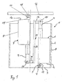
- An in FIG. 1 illustrated height adjustment device 1 has a cylindrical shell-shaped housing 2, the lower end face 3 can be covered open or hygienic reasons. Over the depth of the housing 2 extends at the lower end of a mounting rail 4, which has at least one passage opening for a fastening bolt 5.
- the two electric motors 6, 7 each have a cylindrical housing 8, from which a spindle rod 9 axially slidably extends outwardly on one end face.
- a fork-like projection 11 of the first electric motor 6 engages over the mounting rail 4 and has in the fork-shaped part through holes for the fastening bolt 5, so that the first electric motor 6 is fixed to the rail 4 by means of the fastening bolt 5.
- the two electric motors 6, 7 are arranged in the housing 2 next to each other, but antiparallel to each other.
- the two spindle rods 9 are partially extended.
- a connecting part 12 is fixed, which consists of a height distance between the two ends of the spindle rod 9 bridging middle piece 13 and two at the ends of the central piece 13 at right angles approaches 14.
- the lugs 14 are diametrically opposed to each other with respect to the center axis of the center piece 13, thus pointing in opposite directions.
- the attachment of the lugs 14 to the spindle rods 9 can be done in an analogous manner with a forked end of the spindle rod 9, in which the projection 14 can be inserted.
- a connecting bolt 15 which cause relative to the movement of the spindle rods 9 in the direction of the height rigid attachment of the connecting part 12 with the spindle rods 9.
- the two electric motors 6, 7 are preferably synchronized controlled by a common control, so that both electric motors 6, 7 at the same time and in the same way their spindle rods 9 extend out of the housing 8.
- a weight measuring device 17 is arranged between the bottom end 10 of the second electric motor 7 and a head plate 16 arranged above it as a support support.
- the second electric motor 7 is connected to the weight measuring device 17 with a fork-like projection 11.
- a preferably electronic weight sensor 18 is arranged, which contacts the top plate 16.
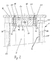
- FIG. 2 is shown in a cross-sectional view of the weight measuring device 17, which is arranged at the top of the height adjustment device 1.
- the weight measuring device 17 has a base body 19, in which a web 20 is formed centrally.
- the web 20 is inserted into the fork-like projection 11 of the second electric motor 7, so that the projection 11 engages over the web 20.
- a fastening bolt 21 is inserted into aligned passage openings of the fork-like projection 11 and the web 20 and thus causes a firm connection of the base body 19 with the height adjustment device. 1
- the base body 19 has on its two sides next to the web 20 two holes 22.
- a spacer sleeve 23 is introduced in each case.
- the spacer sleeve 23 is fastened by means of a washer 24 and a screw 25 to the top plate 16.
- a sliding movement of the inner wall surface of the bore 22 on the outer wall surface of the spacer sleeve 23 a vertical movement of the base body 19 is made possible relative to the top plate 16. Consequently, the base body 19 is movably mounted on the top plate 16.
- a sliding or lubricant between the spacer sleeve 23 and the bore 22 is preferably provided.
- the vertical relative movement between the base body 19 and the top plate 16 is caused by the weight acting on the top plate 16.
- the weight is now forwarded to the weight sensors 18.
- the top plate 16 is moved in the direction of the base body 19, thus decreases with increasing weight, the distance between the base body 19 and the top plate 16 from.
- slide bearings 26 are arranged, in which associated cylindrical piston 27 are guided, which are connected at its upper end to the top plate 16.
- the cylindrical piston 27 ensure that the top plate 16 does not tilt about the fastening bolt 21 as a fulcrum.
- the head plate 16 is held in a horizontal position relative to the direction of movement of the stroke.
- FIG. 3a a cross-section of the base body 19 is shown.
- the main body 19 has in its middle the web 20 with a through hole 28 for receiving the fastening bolt 21 FIG. 2 on.
- a bore 22 is formed in each case.
- the bore has a circular shoulder 29, so that the bore 22 below the shoulder 29 has a larger diameter.
- the paragraph 29 serves as a stop for the washer 24 FIG. 2 ,
- the main body preferably has a length of about 70 to 80 mm, a width of about 10 to 20 mm and a height of about 20 to 30 mm. In the embodiment shown in the figures, the values are 74 mm in length, 15 mm in width and 25 mm in height.
- FIG. 4 illustrates the substructure of a nursing bed and leaves the - shown in this illustration - head plate 16, located in contact with the top plate 16 pressure sensor 18, the relative to the top plate 16 movably mounted weight measuring device 17 and the attached electric motor 7 recognize. Also visible are the cylindrical piston 27, which are guided in plain bearings 26 on the side of the housing 2 and are connected at its upper end to the top plate 16.
- the housing 2 is by screw 31 with a chassis frame 32nd connected, which is provided with wheels 33 and so forms a chassis for the nursing bed.
- the wheelbase of the wheels 33 is preferably wider in comparison to the width of the housing 2.
- FIG. 5 corresponds to the illustration from the FIG. 4 with an additionally illustrated lying surface 34.
- the lying surface 34 is disposed above the top plate 16 and secured thereto. It can be seen from the figures that the lying surface 34 represents the measuring surface for the weight measurement.
- a patient lying above the lying surface 34 and the lying on the bed surface 34 (not shown) lying patient can be monitored with the help of the nursing bed according to the invention in terms of body weight, without having to leave the nursing bed or another increased effort is required.
- use in a changing table and / or a treatment table in medical therapeutic area is possible.
Landscapes
- Health & Medical Sciences (AREA)
- Nursing (AREA)
- Life Sciences & Earth Sciences (AREA)
- Animal Behavior & Ethology (AREA)
- General Health & Medical Sciences (AREA)
- Public Health (AREA)
- Veterinary Medicine (AREA)
- Physics & Mathematics (AREA)
- General Physics & Mathematics (AREA)
- Invalid Beds And Related Equipment (AREA)
- Devices For Medical Bathing And Washing (AREA)
- Thermotherapy And Cooling Therapy Devices (AREA)
Priority Applications (7)
| Application Number | Priority Date | Filing Date | Title |
|---|---|---|---|
| DE502004008353T DE502004008353D1 (de) | 2004-09-08 | 2004-09-08 | Pflegebett |
| DK04021259T DK1634558T3 (da) | 2004-09-08 | 2004-09-08 | Plejeseng |
| PL04021259T PL1634558T3 (pl) | 2004-09-08 | 2004-09-08 | Łóżko pielęgnacyjne |
| AT04021259T ATE412394T1 (de) | 2004-09-08 | 2004-09-08 | Pflegebett |
| EP04021259A EP1634558B1 (de) | 2004-09-08 | 2004-09-08 | Pflegebett |
| ES04021259T ES2316905T3 (es) | 2004-09-08 | 2004-09-08 | Cama para cuidados. |
| PCT/EP2005/009626 WO2006027237A1 (de) | 2004-09-08 | 2005-09-08 | Pflegebett |
Applications Claiming Priority (1)
| Application Number | Priority Date | Filing Date | Title |
|---|---|---|---|
| EP04021259A EP1634558B1 (de) | 2004-09-08 | 2004-09-08 | Pflegebett |
Publications (2)
| Publication Number | Publication Date |
|---|---|
| EP1634558A1 EP1634558A1 (de) | 2006-03-15 |
| EP1634558B1 true EP1634558B1 (de) | 2008-10-29 |
Family
ID=34926447
Family Applications (1)
| Application Number | Title | Priority Date | Filing Date |
|---|---|---|---|
| EP04021259A Expired - Lifetime EP1634558B1 (de) | 2004-09-08 | 2004-09-08 | Pflegebett |
Country Status (7)
| Country | Link |
|---|---|
| EP (1) | EP1634558B1 (pl) |
| AT (1) | ATE412394T1 (pl) |
| DE (1) | DE502004008353D1 (pl) |
| DK (1) | DK1634558T3 (pl) |
| ES (1) | ES2316905T3 (pl) |
| PL (1) | PL1634558T3 (pl) |
| WO (1) | WO2006027237A1 (pl) |
Cited By (1)
| Publication number | Priority date | Publication date | Assignee | Title |
|---|---|---|---|---|
| CN108992256A (zh) * | 2018-08-24 | 2018-12-14 | 南方医科大学南方医院 | 透析患者用称重轮椅 |
Families Citing this family (6)
| Publication number | Priority date | Publication date | Assignee | Title |
|---|---|---|---|---|
| EP2020217B1 (de) | 2007-08-03 | 2011-04-27 | TRUMPF Medizin Systeme GmbH | Operationstisch |
| PL2175759T3 (pl) | 2007-08-11 | 2012-05-31 | Linak As | Mebel wypoczynkowy, jak łóżko lub krzesło |
| US8717181B2 (en) | 2010-07-29 | 2014-05-06 | Hill-Rom Services, Inc. | Bed exit alert silence with automatic re-enable |
| DE102010051126A1 (de) | 2010-11-11 | 2012-05-16 | Berchtold Holding Gmbh | Operationstisch |
| WO2012066580A2 (en) * | 2010-11-19 | 2012-05-24 | Sundaram Medical Devices (P) Ltd | Hospital bed |
| CZ2016582A3 (cs) * | 2016-09-20 | 2017-07-12 | BORCAD Medical a.s. | Zdravotnický prostředek s teleskopickým podpěrným sloupem |
Family Cites Families (6)
| Publication number | Priority date | Publication date | Assignee | Title |
|---|---|---|---|---|
| DE29707518U1 (de) * | 1997-03-01 | 1997-08-14 | Heins, Uwe, 76473 Iffezheim | Gerät zur automatischen Gewichtsfeststellung von menschlichen oder tierischen Patienten zur Vorbereitung der Anästhesie |
| DE29917639U1 (de) * | 1998-10-06 | 2000-03-16 | Takata Corp., Shiga | Sitzgewichtsmeßvorrichtung |
| DE29918805U1 (de) | 1999-10-26 | 2000-01-20 | Bangemann, Eckhard, 38312 Börßum | Krankenhauspflegebett |
| ATE482635T1 (de) * | 2002-03-18 | 2010-10-15 | Hill Rom Services Inc | Krankenbett mit einer geregelten aufblasbaren auflage |
| DE10215395C1 (de) | 2002-04-08 | 2003-10-23 | Eckhard Bangemann | Pflegebett |
| US6866288B2 (en) * | 2002-04-10 | 2005-03-15 | Willis Martin | Convertible wheelchair and separate lift module for connecting to and elevating the wheelchair |
-
2004
- 2004-09-08 PL PL04021259T patent/PL1634558T3/pl unknown
- 2004-09-08 ES ES04021259T patent/ES2316905T3/es not_active Expired - Lifetime
- 2004-09-08 EP EP04021259A patent/EP1634558B1/de not_active Expired - Lifetime
- 2004-09-08 DK DK04021259T patent/DK1634558T3/da active
- 2004-09-08 AT AT04021259T patent/ATE412394T1/de not_active IP Right Cessation
- 2004-09-08 DE DE502004008353T patent/DE502004008353D1/de not_active Expired - Lifetime
-
2005
- 2005-09-08 WO PCT/EP2005/009626 patent/WO2006027237A1/de not_active Ceased
Cited By (2)
| Publication number | Priority date | Publication date | Assignee | Title |
|---|---|---|---|---|
| CN108992256A (zh) * | 2018-08-24 | 2018-12-14 | 南方医科大学南方医院 | 透析患者用称重轮椅 |
| CN108992256B (zh) * | 2018-08-24 | 2019-09-27 | 南方医科大学南方医院 | 透析患者用称重轮椅 |
Also Published As
| Publication number | Publication date |
|---|---|
| WO2006027237A1 (de) | 2006-03-16 |
| ES2316905T3 (es) | 2009-04-16 |
| ATE412394T1 (de) | 2008-11-15 |
| DK1634558T3 (da) | 2009-03-09 |
| PL1634558T3 (pl) | 2009-05-29 |
| EP1634558A1 (de) | 2006-03-15 |
| DE502004008353D1 (de) | 2008-12-11 |
Similar Documents
| Publication | Publication Date | Title |
|---|---|---|
| DE3535303A1 (de) | Verstellbarer arbeitstisch | |
| EP1634558A1 (de) | Pflegebett | |
| DE2310603A1 (de) | Bett, insbesondere krankenbett | |
| EP2183554A1 (de) | Liegevorrichtung | |
| EP1001247A2 (de) | Positionsgeber zur Anstellhubwegmessung der Walzen eines Walzgerüstes | |
| DE4039097C2 (de) | Höhenverstellbarer Fuß für Möbel | |
| DE3516539C2 (pl) | ||
| EP0242811B1 (de) | An einer senkrechten Wand montierbares Schrank- und/oder Tischmöbel | |
| DE3305074A1 (de) | Hebebuehne, die durch eine mechanische hoehenverstelleinrichtung heb- und senkbar ist | |
| AT396745B (de) | Verstellbare gelenkuntermatratze für ein spital- oder pflegebett | |
| DE19626854B4 (de) | Traggestell für einen höhenverstellbaren Tisch | |
| DE102021100387A1 (de) | Luftbefüllungsvorrichtung | |
| DE19626855B4 (de) | Traggestell für einen höhenverstellbaren Tisch | |
| DE4442039A1 (de) | Vorrichtung zum Hochlagern der Beine | |
| DE10215395C1 (de) | Pflegebett | |
| AT412836B (de) | Stativ zur halterung medizinischer geräte | |
| DE3902334A1 (de) | Bett mit einem zumindest in der neigung verstellbaren liegeelement | |
| DE10113807C1 (de) | Höhenverstellbare Tragsäule eines Behandlungstisches, insbesondere für chirurgische Eingriffe | |
| EP0406462A1 (de) | Behandlungstisch, insbesondere für physikalische Therapie | |
| DE3133026A1 (de) | Vorrichtung zur erfassung mechanischer koerperfunktionen von lebewesen | |
| DE3739782C1 (de) | Stufenbett | |
| EP0916284A2 (de) | Höhenverstellbarer Arbeitstisch | |
| DE212021000352U1 (de) | Patientenlagereinrichtung mit Scherenhub und Waagen | |
| DE9306723U1 (de) | Hebevorrichtung | |
| DE19934484A1 (de) | Eine kompakte in kleiner Bauweise höhenverstellbare Säule, insbesondere für Tisch und Arbeitsplatten |
Legal Events
| Date | Code | Title | Description |
|---|---|---|---|
| PUAI | Public reference made under article 153(3) epc to a published international application that has entered the european phase |
Free format text: ORIGINAL CODE: 0009012 |
|
| 17P | Request for examination filed |
Effective date: 20050910 |
|
| AK | Designated contracting states |
Kind code of ref document: A1 Designated state(s): AT BE BG CH CY CZ DE DK EE ES FI FR GB GR HU IE IT LI LU MC NL PL PT RO SE SI SK TR |
|
| AX | Request for extension of the european patent |
Extension state: AL HR LT LV MK |
|
| AKX | Designation fees paid |
Designated state(s): AT BE BG CH CY CZ DE DK EE ES FI FR GB GR HU IE IT LI LU MC NL PL PT RO SE SI SK TR |
|
| 17Q | First examination report despatched |
Effective date: 20061106 |
|
| GRAP | Despatch of communication of intention to grant a patent |
Free format text: ORIGINAL CODE: EPIDOSNIGR1 |
|
| GRAS | Grant fee paid |
Free format text: ORIGINAL CODE: EPIDOSNIGR3 |
|
| GRAA | (expected) grant |
Free format text: ORIGINAL CODE: 0009210 |
|
| AK | Designated contracting states |
Kind code of ref document: B1 Designated state(s): AT BE BG CH CY CZ DE DK EE ES FI FR GB GR HU IE IT LI LU MC NL PL PT RO SE SI SK TR |
|
| REG | Reference to a national code |
Ref country code: GB Ref legal event code: FG4D Free format text: NOT ENGLISH |
|
| REG | Reference to a national code |
Ref country code: CH Ref legal event code: EP |
|
| REG | Reference to a national code |
Ref country code: IE Ref legal event code: FG4D Free format text: LANGUAGE OF EP DOCUMENT: GERMAN |
|
| REF | Corresponds to: |
Ref document number: 502004008353 Country of ref document: DE Date of ref document: 20081211 Kind code of ref document: P |
|
| REG | Reference to a national code |
Ref country code: CH Ref legal event code: NV Representative=s name: BRAUNPAT BRAUN EDER AG |
|
| REG | Reference to a national code |
Ref country code: SE Ref legal event code: TRGR |
|
| REG | Reference to a national code |
Ref country code: DK Ref legal event code: T3 |
|
| REG | Reference to a national code |
Ref country code: ES Ref legal event code: FG2A Ref document number: 2316905 Country of ref document: ES Kind code of ref document: T3 |
|
| PG25 | Lapsed in a contracting state [announced via postgrant information from national office to epo] |
Ref country code: BG Free format text: LAPSE BECAUSE OF FAILURE TO SUBMIT A TRANSLATION OF THE DESCRIPTION OR TO PAY THE FEE WITHIN THE PRESCRIBED TIME-LIMIT Effective date: 20090129 |
|
| PG25 | Lapsed in a contracting state [announced via postgrant information from national office to epo] |
Ref country code: FI Free format text: LAPSE BECAUSE OF FAILURE TO SUBMIT A TRANSLATION OF THE DESCRIPTION OR TO PAY THE FEE WITHIN THE PRESCRIBED TIME-LIMIT Effective date: 20081029 Ref country code: PT Free format text: LAPSE BECAUSE OF FAILURE TO SUBMIT A TRANSLATION OF THE DESCRIPTION OR TO PAY THE FEE WITHIN THE PRESCRIBED TIME-LIMIT Effective date: 20090330 Ref country code: SI Free format text: LAPSE BECAUSE OF FAILURE TO SUBMIT A TRANSLATION OF THE DESCRIPTION OR TO PAY THE FEE WITHIN THE PRESCRIBED TIME-LIMIT Effective date: 20081029 |
|
| REG | Reference to a national code |
Ref country code: PL Ref legal event code: T3 |
|
| REG | Reference to a national code |
Ref country code: IE Ref legal event code: FD4D |
|
| PG25 | Lapsed in a contracting state [announced via postgrant information from national office to epo] |
Ref country code: RO Free format text: LAPSE BECAUSE OF FAILURE TO SUBMIT A TRANSLATION OF THE DESCRIPTION OR TO PAY THE FEE WITHIN THE PRESCRIBED TIME-LIMIT Effective date: 20081029 Ref country code: IE Free format text: LAPSE BECAUSE OF FAILURE TO SUBMIT A TRANSLATION OF THE DESCRIPTION OR TO PAY THE FEE WITHIN THE PRESCRIBED TIME-LIMIT Effective date: 20081029 Ref country code: EE Free format text: LAPSE BECAUSE OF FAILURE TO SUBMIT A TRANSLATION OF THE DESCRIPTION OR TO PAY THE FEE WITHIN THE PRESCRIBED TIME-LIMIT Effective date: 20081029 |
|
| REG | Reference to a national code |
Ref country code: HU Ref legal event code: AG4A Ref document number: E005513 Country of ref document: HU |
|
| PG25 | Lapsed in a contracting state [announced via postgrant information from national office to epo] |
Ref country code: IT Free format text: LAPSE BECAUSE OF FAILURE TO SUBMIT A TRANSLATION OF THE DESCRIPTION OR TO PAY THE FEE WITHIN THE PRESCRIBED TIME-LIMIT Effective date: 20081029 |
|
| PLBE | No opposition filed within time limit |
Free format text: ORIGINAL CODE: 0009261 |
|
| STAA | Information on the status of an ep patent application or granted ep patent |
Free format text: STATUS: NO OPPOSITION FILED WITHIN TIME LIMIT |
|
| PG25 | Lapsed in a contracting state [announced via postgrant information from national office to epo] |
Ref country code: SK Free format text: LAPSE BECAUSE OF FAILURE TO SUBMIT A TRANSLATION OF THE DESCRIPTION OR TO PAY THE FEE WITHIN THE PRESCRIBED TIME-LIMIT Effective date: 20081029 |
|
| 26N | No opposition filed |
Effective date: 20090730 |
|
| BERE | Be: lapsed |
Owner name: BANGEMANN ECKHARD Effective date: 20090930 |
|
| REG | Reference to a national code |
Ref country code: NL Ref legal event code: V1 Effective date: 20100401 |
|
| PG25 | Lapsed in a contracting state [announced via postgrant information from national office to epo] |
Ref country code: CZ Free format text: LAPSE BECAUSE OF NON-PAYMENT OF DUE FEES Effective date: 20090908 Ref country code: MC Free format text: LAPSE BECAUSE OF NON-PAYMENT OF DUE FEES Effective date: 20090930 |
|
| REG | Reference to a national code |
Ref country code: CH Ref legal event code: PL |
|
| EUG | Se: european patent has lapsed | ||
| REG | Reference to a national code |
Ref country code: DK Ref legal event code: EBP |
|
| GBPC | Gb: european patent ceased through non-payment of renewal fee |
Effective date: 20090908 |
|
| PG25 | Lapsed in a contracting state [announced via postgrant information from national office to epo] |
Ref country code: NL Free format text: LAPSE BECAUSE OF NON-PAYMENT OF DUE FEES Effective date: 20100401 Ref country code: HU Free format text: LAPSE BECAUSE OF NON-PAYMENT OF DUE FEES Effective date: 20090909 |
|
| PG25 | Lapsed in a contracting state [announced via postgrant information from national office to epo] |
Ref country code: BE Free format text: LAPSE BECAUSE OF NON-PAYMENT OF DUE FEES Effective date: 20090930 |
|
| PGFP | Annual fee paid to national office [announced via postgrant information from national office to epo] |
Ref country code: NL Payment date: 20100330 Year of fee payment: 6 |
|
| REG | Reference to a national code |
Ref country code: NL Ref legal event code: BK Free format text: ONTERECHT VERVALLEN 01.04.2010PUBLIKATIE VERVAL IE 21.04.2010IE NUMMER 2010/10 |
|
| PG25 | Lapsed in a contracting state [announced via postgrant information from national office to epo] |
Ref country code: LI Free format text: LAPSE BECAUSE OF NON-PAYMENT OF DUE FEES Effective date: 20090930 Ref country code: GR Free format text: LAPSE BECAUSE OF FAILURE TO SUBMIT A TRANSLATION OF THE DESCRIPTION OR TO PAY THE FEE WITHIN THE PRESCRIBED TIME-LIMIT Effective date: 20090130 Ref country code: CH Free format text: LAPSE BECAUSE OF NON-PAYMENT OF DUE FEES Effective date: 20090930 |
|
| PGFP | Annual fee paid to national office [announced via postgrant information from national office to epo] |
Ref country code: ES Payment date: 20100921 Year of fee payment: 7 |
|
| PG25 | Lapsed in a contracting state [announced via postgrant information from national office to epo] |
Ref country code: GB Free format text: LAPSE BECAUSE OF NON-PAYMENT OF DUE FEES Effective date: 20090908 Ref country code: AT Free format text: LAPSE BECAUSE OF NON-PAYMENT OF DUE FEES Effective date: 20090908 |
|
| PGFP | Annual fee paid to national office [announced via postgrant information from national office to epo] |
Ref country code: FR Payment date: 20101006 Year of fee payment: 7 |
|
| PG25 | Lapsed in a contracting state [announced via postgrant information from national office to epo] |
Ref country code: DK Free format text: LAPSE BECAUSE OF NON-PAYMENT OF DUE FEES Effective date: 20090930 |
|
| REG | Reference to a national code |
Ref country code: NL Ref legal event code: V1 Effective date: 20110401 |
|
| PG25 | Lapsed in a contracting state [announced via postgrant information from national office to epo] |
Ref country code: LU Free format text: LAPSE BECAUSE OF NON-PAYMENT OF DUE FEES Effective date: 20090908 |
|
| PG25 | Lapsed in a contracting state [announced via postgrant information from national office to epo] |
Ref country code: SE Free format text: LAPSE BECAUSE OF NON-PAYMENT OF DUE FEES Effective date: 20090909 |
|
| PG25 | Lapsed in a contracting state [announced via postgrant information from national office to epo] |
Ref country code: PL Free format text: LAPSE BECAUSE OF NON-PAYMENT OF DUE FEES Effective date: 20090908 Ref country code: NL Free format text: LAPSE BECAUSE OF NON-PAYMENT OF DUE FEES Effective date: 20110401 |
|
| REG | Reference to a national code |
Ref country code: PL Ref legal event code: LAPE |
|
| PG25 | Lapsed in a contracting state [announced via postgrant information from national office to epo] |
Ref country code: CY Free format text: LAPSE BECAUSE OF FAILURE TO SUBMIT A TRANSLATION OF THE DESCRIPTION OR TO PAY THE FEE WITHIN THE PRESCRIBED TIME-LIMIT Effective date: 20081029 |
|
| REG | Reference to a national code |
Ref country code: FR Ref legal event code: ST Effective date: 20120531 |
|
| PG25 | Lapsed in a contracting state [announced via postgrant information from national office to epo] |
Ref country code: FR Free format text: LAPSE BECAUSE OF NON-PAYMENT OF DUE FEES Effective date: 20110930 |
|
| REG | Reference to a national code |
Ref country code: ES Ref legal event code: FD2A Effective date: 20130530 |
|
| PG25 | Lapsed in a contracting state [announced via postgrant information from national office to epo] |
Ref country code: ES Free format text: LAPSE BECAUSE OF NON-PAYMENT OF DUE FEES Effective date: 20110909 |
|
| PG25 | Lapsed in a contracting state [announced via postgrant information from national office to epo] |
Ref country code: TR Free format text: LAPSE BECAUSE OF FAILURE TO SUBMIT A TRANSLATION OF THE DESCRIPTION OR TO PAY THE FEE WITHIN THE PRESCRIBED TIME-LIMIT Effective date: 20081029 |
|
| PGFP | Annual fee paid to national office [announced via postgrant information from national office to epo] |
Ref country code: DE Payment date: 20140930 Year of fee payment: 11 |
|
| REG | Reference to a national code |
Ref country code: DE Ref legal event code: R082 Ref document number: 502004008353 Country of ref document: DE Representative=s name: GRAMM, LINS & PARTNER PATENT- UND RECHTSANWAEL, DE |
|
| REG | Reference to a national code |
Ref country code: DE Ref legal event code: R119 Ref document number: 502004008353 Country of ref document: DE |
|
| PG25 | Lapsed in a contracting state [announced via postgrant information from national office to epo] |
Ref country code: DE Free format text: LAPSE BECAUSE OF NON-PAYMENT OF DUE FEES Effective date: 20160401 |