EP1633497B1 - Halterung für ein ultraschallhorn - Google Patents
Halterung für ein ultraschallhorn Download PDFInfo
- Publication number
- EP1633497B1 EP1633497B1 EP04750432.9A EP04750432A EP1633497B1 EP 1633497 B1 EP1633497 B1 EP 1633497B1 EP 04750432 A EP04750432 A EP 04750432A EP 1633497 B1 EP1633497 B1 EP 1633497B1
- Authority
- EP
- European Patent Office
- Prior art keywords
- horn
- mount
- bearing surface
- ultrasonic horn
- mounting member
- Prior art date
- Legal status (The legal status is an assumption and is not a legal conclusion. Google has not performed a legal analysis and makes no representation as to the accuracy of the status listed.)
- Expired - Lifetime
Links
- 238000000034 method Methods 0.000 claims description 12
- 230000033001 locomotion Effects 0.000 claims description 10
- 239000007787 solid Substances 0.000 claims description 6
- 238000004519 manufacturing process Methods 0.000 claims description 3
- 238000006073 displacement reaction Methods 0.000 description 24
- 238000003466 welding Methods 0.000 description 23
- 239000000463 material Substances 0.000 description 9
- 238000002955 isolation Methods 0.000 description 6
- 230000008878 coupling Effects 0.000 description 5
- 238000010168 coupling process Methods 0.000 description 5
- 238000005859 coupling reaction Methods 0.000 description 5
- 229910001369 Brass Inorganic materials 0.000 description 2
- RTAQQCXQSZGOHL-UHFFFAOYSA-N Titanium Chemical compound [Ti] RTAQQCXQSZGOHL-UHFFFAOYSA-N 0.000 description 2
- 239000000853 adhesive Substances 0.000 description 2
- 230000001070 adhesive effect Effects 0.000 description 2
- XAGFODPZIPBFFR-UHFFFAOYSA-N aluminium Chemical compound [Al] XAGFODPZIPBFFR-UHFFFAOYSA-N 0.000 description 2
- 229910052782 aluminium Inorganic materials 0.000 description 2
- 239000010951 brass Substances 0.000 description 2
- 238000010276 construction Methods 0.000 description 2
- 239000010936 titanium Substances 0.000 description 2
- 229910052719 titanium Inorganic materials 0.000 description 2
- 229910000615 4150 steel Inorganic materials 0.000 description 1
- 102000000393 Ghrelin Receptors Human genes 0.000 description 1
- 108010016122 Ghrelin Receptors Proteins 0.000 description 1
- 229910000831 Steel Inorganic materials 0.000 description 1
- 230000006978 adaptation Effects 0.000 description 1
- 230000004323 axial length Effects 0.000 description 1
- 230000005540 biological transmission Effects 0.000 description 1
- 239000004744 fabric Substances 0.000 description 1
- 239000012528 membrane Substances 0.000 description 1
- 230000010355 oscillation Effects 0.000 description 1
- 238000007789 sealing Methods 0.000 description 1
- 239000010959 steel Substances 0.000 description 1
- 239000000126 substance Substances 0.000 description 1
- 238000005493 welding type Methods 0.000 description 1
Images


Classifications
-
- B—PERFORMING OPERATIONS; TRANSPORTING
- B06—GENERATING OR TRANSMITTING MECHANICAL VIBRATIONS IN GENERAL
- B06B—METHODS OR APPARATUS FOR GENERATING OR TRANSMITTING MECHANICAL VIBRATIONS OF INFRASONIC, SONIC, OR ULTRASONIC FREQUENCY, e.g. FOR PERFORMING MECHANICAL WORK IN GENERAL
- B06B3/00—Methods or apparatus specially adapted for transmitting mechanical vibrations of infrasonic, sonic, or ultrasonic frequency
-
- B—PERFORMING OPERATIONS; TRANSPORTING
- B23—MACHINE TOOLS; METAL-WORKING NOT OTHERWISE PROVIDED FOR
- B23K—SOLDERING OR UNSOLDERING; WELDING; CLADDING OR PLATING BY SOLDERING OR WELDING; CUTTING BY APPLYING HEAT LOCALLY, e.g. FLAME CUTTING; WORKING BY LASER BEAM
- B23K20/00—Non-electric welding by applying impact or other pressure, with or without the application of heat, e.g. cladding or plating
- B23K20/10—Non-electric welding by applying impact or other pressure, with or without the application of heat, e.g. cladding or plating making use of vibrations, e.g. ultrasonic welding
- B23K20/106—Features related to sonotrodes
-
- B—PERFORMING OPERATIONS; TRANSPORTING
- B23—MACHINE TOOLS; METAL-WORKING NOT OTHERWISE PROVIDED FOR
- B23K—SOLDERING OR UNSOLDERING; WELDING; CLADDING OR PLATING BY SOLDERING OR WELDING; CUTTING BY APPLYING HEAT LOCALLY, e.g. FLAME CUTTING; WORKING BY LASER BEAM
- B23K5/00—Gas flame welding
- B23K5/20—Gas flame welding making use of vibrations, e.g. supersonic vibrations
-
- B—PERFORMING OPERATIONS; TRANSPORTING
- B29—WORKING OF PLASTICS; WORKING OF SUBSTANCES IN A PLASTIC STATE IN GENERAL
- B29C—SHAPING OR JOINING OF PLASTICS; SHAPING OF MATERIAL IN A PLASTIC STATE, NOT OTHERWISE PROVIDED FOR; AFTER-TREATMENT OF THE SHAPED PRODUCTS, e.g. REPAIRING
- B29C65/00—Joining or sealing of preformed parts, e.g. welding of plastics materials; Apparatus therefor
- B29C65/02—Joining or sealing of preformed parts, e.g. welding of plastics materials; Apparatus therefor by heating, with or without pressure
- B29C65/08—Joining or sealing of preformed parts, e.g. welding of plastics materials; Apparatus therefor by heating, with or without pressure using ultrasonic vibrations
- B29C65/083—Joining or sealing of preformed parts, e.g. welding of plastics materials; Apparatus therefor by heating, with or without pressure using ultrasonic vibrations using a rotary sonotrode or a rotary anvil
- B29C65/085—Joining or sealing of preformed parts, e.g. welding of plastics materials; Apparatus therefor by heating, with or without pressure using ultrasonic vibrations using a rotary sonotrode or a rotary anvil using a rotary sonotrode
-
- B—PERFORMING OPERATIONS; TRANSPORTING
- B29—WORKING OF PLASTICS; WORKING OF SUBSTANCES IN A PLASTIC STATE IN GENERAL
- B29C—SHAPING OR JOINING OF PLASTICS; SHAPING OF MATERIAL IN A PLASTIC STATE, NOT OTHERWISE PROVIDED FOR; AFTER-TREATMENT OF THE SHAPED PRODUCTS, e.g. REPAIRING
- B29C66/00—General aspects of processes or apparatus for joining preformed parts
- B29C66/80—General aspects of machine operations or constructions and parts thereof
- B29C66/81—General aspects of the pressing elements, i.e. the elements applying pressure on the parts to be joined in the area to be joined, e.g. the welding jaws or clamps
- B29C66/814—General aspects of the pressing elements, i.e. the elements applying pressure on the parts to be joined in the area to be joined, e.g. the welding jaws or clamps characterised by the design of the pressing elements, e.g. of the welding jaws or clamps
- B29C66/8141—General aspects of the pressing elements, i.e. the elements applying pressure on the parts to be joined in the area to be joined, e.g. the welding jaws or clamps characterised by the design of the pressing elements, e.g. of the welding jaws or clamps characterised by the surface geometry of the part of the pressing elements, e.g. welding jaws or clamps, coming into contact with the parts to be joined
- B29C66/81431—General aspects of the pressing elements, i.e. the elements applying pressure on the parts to be joined in the area to be joined, e.g. the welding jaws or clamps characterised by the design of the pressing elements, e.g. of the welding jaws or clamps characterised by the surface geometry of the part of the pressing elements, e.g. welding jaws or clamps, coming into contact with the parts to be joined comprising a single cavity, e.g. a groove
-
- B—PERFORMING OPERATIONS; TRANSPORTING
- B29—WORKING OF PLASTICS; WORKING OF SUBSTANCES IN A PLASTIC STATE IN GENERAL
- B29C—SHAPING OR JOINING OF PLASTICS; SHAPING OF MATERIAL IN A PLASTIC STATE, NOT OTHERWISE PROVIDED FOR; AFTER-TREATMENT OF THE SHAPED PRODUCTS, e.g. REPAIRING
- B29C66/00—General aspects of processes or apparatus for joining preformed parts
- B29C66/80—General aspects of machine operations or constructions and parts thereof
- B29C66/81—General aspects of the pressing elements, i.e. the elements applying pressure on the parts to be joined in the area to be joined, e.g. the welding jaws or clamps
- B29C66/816—General aspects of the pressing elements, i.e. the elements applying pressure on the parts to be joined in the area to be joined, e.g. the welding jaws or clamps characterised by the mounting of the pressing elements, e.g. of the welding jaws or clamps
-
- B—PERFORMING OPERATIONS; TRANSPORTING
- B29—WORKING OF PLASTICS; WORKING OF SUBSTANCES IN A PLASTIC STATE IN GENERAL
- B29C—SHAPING OR JOINING OF PLASTICS; SHAPING OF MATERIAL IN A PLASTIC STATE, NOT OTHERWISE PROVIDED FOR; AFTER-TREATMENT OF THE SHAPED PRODUCTS, e.g. REPAIRING
- B29C66/00—General aspects of processes or apparatus for joining preformed parts
- B29C66/80—General aspects of machine operations or constructions and parts thereof
- B29C66/83—General aspects of machine operations or constructions and parts thereof characterised by the movement of the joining or pressing tools
- B29C66/834—General aspects of machine operations or constructions and parts thereof characterised by the movement of the joining or pressing tools moving with the parts to be joined
- B29C66/8341—Roller, cylinder or drum types; Band or belt types; Ball types
- B29C66/83411—Roller, cylinder or drum types
- B29C66/83417—Roller, cylinder or drum types said rollers, cylinders or drums being hollow
-
- B—PERFORMING OPERATIONS; TRANSPORTING
- B29—WORKING OF PLASTICS; WORKING OF SUBSTANCES IN A PLASTIC STATE IN GENERAL
- B29C—SHAPING OR JOINING OF PLASTICS; SHAPING OF MATERIAL IN A PLASTIC STATE, NOT OTHERWISE PROVIDED FOR; AFTER-TREATMENT OF THE SHAPED PRODUCTS, e.g. REPAIRING
- B29C66/00—General aspects of processes or apparatus for joining preformed parts
- B29C66/90—Measuring or controlling the joining process
- B29C66/95—Measuring or controlling the joining process by measuring or controlling specific variables not covered by groups B29C66/91 - B29C66/94
- B29C66/951—Measuring or controlling the joining process by measuring or controlling specific variables not covered by groups B29C66/91 - B29C66/94 by measuring or controlling the vibration frequency and/or the vibration amplitude of vibrating joining tools, e.g. of ultrasonic welding tools
- B29C66/9512—Measuring or controlling the joining process by measuring or controlling specific variables not covered by groups B29C66/91 - B29C66/94 by measuring or controlling the vibration frequency and/or the vibration amplitude of vibrating joining tools, e.g. of ultrasonic welding tools by controlling their vibration frequency
-
- B—PERFORMING OPERATIONS; TRANSPORTING
- B29—WORKING OF PLASTICS; WORKING OF SUBSTANCES IN A PLASTIC STATE IN GENERAL
- B29C—SHAPING OR JOINING OF PLASTICS; SHAPING OF MATERIAL IN A PLASTIC STATE, NOT OTHERWISE PROVIDED FOR; AFTER-TREATMENT OF THE SHAPED PRODUCTS, e.g. REPAIRING
- B29C65/00—Joining or sealing of preformed parts, e.g. welding of plastics materials; Apparatus therefor
- B29C65/02—Joining or sealing of preformed parts, e.g. welding of plastics materials; Apparatus therefor by heating, with or without pressure
- B29C65/08—Joining or sealing of preformed parts, e.g. welding of plastics materials; Apparatus therefor by heating, with or without pressure using ultrasonic vibrations
- B29C65/083—Joining or sealing of preformed parts, e.g. welding of plastics materials; Apparatus therefor by heating, with or without pressure using ultrasonic vibrations using a rotary sonotrode or a rotary anvil
- B29C65/086—Joining or sealing of preformed parts, e.g. welding of plastics materials; Apparatus therefor by heating, with or without pressure using ultrasonic vibrations using a rotary sonotrode or a rotary anvil using a rotary anvil
-
- B—PERFORMING OPERATIONS; TRANSPORTING
- B29—WORKING OF PLASTICS; WORKING OF SUBSTANCES IN A PLASTIC STATE IN GENERAL
- B29C—SHAPING OR JOINING OF PLASTICS; SHAPING OF MATERIAL IN A PLASTIC STATE, NOT OTHERWISE PROVIDED FOR; AFTER-TREATMENT OF THE SHAPED PRODUCTS, e.g. REPAIRING
- B29C66/00—General aspects of processes or apparatus for joining preformed parts
- B29C66/90—Measuring or controlling the joining process
- B29C66/95—Measuring or controlling the joining process by measuring or controlling specific variables not covered by groups B29C66/91 - B29C66/94
- B29C66/951—Measuring or controlling the joining process by measuring or controlling specific variables not covered by groups B29C66/91 - B29C66/94 by measuring or controlling the vibration frequency and/or the vibration amplitude of vibrating joining tools, e.g. of ultrasonic welding tools
- B29C66/9513—Measuring or controlling the joining process by measuring or controlling specific variables not covered by groups B29C66/91 - B29C66/94 by measuring or controlling the vibration frequency and/or the vibration amplitude of vibrating joining tools, e.g. of ultrasonic welding tools characterised by specific vibration frequency values or ranges
-
- B—PERFORMING OPERATIONS; TRANSPORTING
- B29—WORKING OF PLASTICS; WORKING OF SUBSTANCES IN A PLASTIC STATE IN GENERAL
- B29C—SHAPING OR JOINING OF PLASTICS; SHAPING OF MATERIAL IN A PLASTIC STATE, NOT OTHERWISE PROVIDED FOR; AFTER-TREATMENT OF THE SHAPED PRODUCTS, e.g. REPAIRING
- B29C66/00—General aspects of processes or apparatus for joining preformed parts
- B29C66/90—Measuring or controlling the joining process
- B29C66/95—Measuring or controlling the joining process by measuring or controlling specific variables not covered by groups B29C66/91 - B29C66/94
- B29C66/951—Measuring or controlling the joining process by measuring or controlling specific variables not covered by groups B29C66/91 - B29C66/94 by measuring or controlling the vibration frequency and/or the vibration amplitude of vibrating joining tools, e.g. of ultrasonic welding tools
- B29C66/9517—Measuring or controlling the joining process by measuring or controlling specific variables not covered by groups B29C66/91 - B29C66/94 by measuring or controlling the vibration frequency and/or the vibration amplitude of vibrating joining tools, e.g. of ultrasonic welding tools characterised by specific vibration amplitude values or ranges
Definitions
- This invention of the present disclosure is related to ultrasonic welding mounts, and particularly to system, apparatus and method for mounting an ultrasonic horn having a predetermined resonant frequency with a mount having about the same resonant frequency.
- Ultrasonic welding is typically used to join multiple parts together using vibrations converted into heat energy.
- Common types of ultrasonic welding are plunge and continuous welding, for example, scan or rotary welding.
- plunge welding an ultrasonic horn plunges (travels towards the parts) and transmits vibrations into a top part.
- the ultrasonic horn In continuous welding, the ultrasonic horn is typically stationary or rotating and the part is moved beneath it.
- Continuous ultrasonic welding is typically used for sealing fabrics, films, and other parts.
- Scan welding is a type of continuous welding in which the part moves. The plastic part is scanned beneath one or more stationary horns. Each of the ultrasonic welding types involves a horn.
- a rotary horn includes a shaft with input and output ends, and a welding portion mounted on and coaxial with the output end.
- the diameter of the welding portion is typically greater than the diameter of the shaft.
- the welding portion has a cylindrical weld face having a diameter that expands and contracts with the application of vibration energy.
- a rotary horn is cylindrical and rotates about a longitudinal axis. The input vibration is in the axial direction and the output vibration is in the radial direction. The horn and anvil are close to each other, and the anvil can rotate in the opposite direction of the horn.
- the part (or parts) to be welded passes between the cylindrical surfaces at a linear velocity, equal to the tangential velocity of the cylindrical surfaces. Matching the tangential velocities of the horn and the anvil with the linear velocity of the material is tends to minimize the drag between the horn and the material.
- WO 03/070387 A2 describes a mounting system for a vibrational element with a longitudinal axis, an outer surface and an axial displacement node.
- the mounting system includes an isolation member which has an isolation surface, an isolating body, and an engaging portion.
- the engaging portion is immovably secured to the isolation member and extends radially inward from the isolation body at a point radially opposite the isolation surface.
- the engaging portion is disposed so as to engage to the outer surface of the vibrational element.
- US 3 350 582 A discloses an ultrasonic vibratory tool in which the transducer for the tool is provided with a supporting structure separate from that of the tool itself.
- a wire mesh pad element or a resilient electrically conductive adhesive is interposed between the transducer and its support to absorb the vibrations of the transducer and to provide a series of electrically conductive paths therebetween.
- An electrically conductive adhesive also is positioned between the transducer and the tool to enable the transmission of electrical as well as mechanical energy thereto.
- US 2 866 911 A describes an elongated mechanical vibrator and means attached to one end thereof, which sets the vibrator into longitudinal oscillations.
- the vibrator has a length equal substantially to one or more integral half wavelength of the vibrations therein and has antinodes at its ends.
- a substantially rigid cylinder is attached to the vibrator in the vicinity of a node of the natural resonant frequency of the vibrator.
- US 6 547 903 B1 discloses an ultrasonic processing apparatus which can include a rotatable, ultrasonic horn member that is operatively joined to an isolation member which has high rigidity.
- a rotatable anvil member can be cooperatively positioned to provide a selected horn-anvil gap, and an automated drive can be connected to an actuator to automatically adjust the horn-anvil gap.
- US 5 590 866 A discloses a mount for a vibratory member, such as an elongate half wavelength resonator, includes a pair of cylindrical flexural tubes. Each tube is coupled with one end to the nodal region of the member and the other end of each tube coupled to a stationary member. The axial length and the thickness of the tubes are selected to enable the tubes to flex radially responsive to the substantially radial vibrations manifest at the nodal region of the member so as to decouple the vibrations of the member from the stationary member.
- GB 877 966 A describes a magnetostrictive vibrator comprising a transducer and a coupling which are supported by a half-wave element which in turn is held at a node by a handle.
- the halfwave element is secured to the vibrator at an antinode but the free end of the element is constructed of more massive proportions so that the quarter-wave path from the handle to the free end is shorter than the quarter-wave path to the node.
- a node is a position of the horn that has zero displacement in one or more directions.
- a node is a point or region on an ultrasonic horn where the longitudinal displacement is negligible or zero and the radial displacement is at or near its maximum when the horn is in resonance.
- An anti-node is a point or region where the longitudinal displacement is at or near its maximum and the redial displacement is at or near its minimum.
- Non-nodal mount With a nodal mount, the horn can be held or grasped rigidly.
- One type of non-nodal mount is used at an anti-node of the horn. Anti-nodes are areas of maximum longitudinal displacement of the horn (or other component, such as a booster). Attaching mounting systems at a non-nodal location, such as the anti-node, requires the mount to be designed to isolate the vibration from the horn. Non-nodal mounts typically require some flexible elements because the horn surface is moving (vibrating) at the point where the mount is located.
- the system includes a horn having a resonance at a predetermined frequency and a mounting member having a resonance at about the same predetermined frequency.
- the mounting member is coupled to the horn at a point where the horn has a node at the predetermined frequency.
- the horn is a rotary horn.
- the system includes a base element, a pair of flanges extending outwardly from the base element, and a mount element extending inwardly from the base element.
- the mounting member includes a base element and a pair of flanges extending outwardly from the base element and defining an exterior bearing surface.
- the mounting member also includes a mount element extending inwardly from the base element and defining an interior bearing surface.
- the exterior bearing surface is a node when the interior bearing surface is driven at a predetermined frequency. In one example embodiment, the motion of the exterior bearing surface is less than two percent of the motion of the interior bearing surface when the mount element is driven at the predetermined frequency.
- the mounting member has a resonant frequency of about 20,000 Hertz. In another example embodiment, the mounting member has a resonant frequency of about 40,000 Hertz.
- the mounting member is of a unitary construction.
- Another aspect of the present invention is directed to a method of mounting an ultrasonic horn.
- the method includes providing a horn having a resonance at a predetermined frequency and attaching a mount having a resonance at about said predetermined frequency to the horn at a point where the horn has a node at the predetermined frequency.
- the horn is a rotary horn.
- the present disclosure is directed to an ultrasonic welding system.
- the system includes a vibrating member and a mounting arrangement.
- the vibrating member has at least one excitable resonant frequency. Typically, the resonant frequency is 20,000 to 40,000 Hertz, though other resonant frequencies can be used.
- the vibrating member is typically a rotary or linear ultrasonic horn.
- the mounting arrangement holds the vibrating member at a nodal region on the vibrating member.
- the mounting arrangement can hold a booster attached to the horn at a nodal region on the booster.
- the mounting arrangement includes at least one mounting member. Typically, two mounting members hold a rotary horn, each mounting member being located at a nodal region of maximum radial displacement of the horn.
- one mounting member holds the vibrating member at a nodal region of a booster section coupled to the linear horn.
- the mounting member includes an excitable mode with a resonant frequency about the same as the resonant frequency of the vibrating member.
- the vibrating member has a predetermined frequency, which means a frequency that is selected or designed into the vibrating member.
- the predetermined resonant frequency of the mounting member is typically within 10 percent of the resonant frequency of the vibrating member. More typically, the resonant frequency of the mounting member is typically within 2 percent of the resonant frequency of the vibrating member.
- the predetermined frequency of the horn can be varied depending on the conditions under which the horn will be used.
- the horn can be designed to have a specific predetermined resonant frequency by varying the variables in the design, for example, the thickness or radius of the horn, the materials of construction or material properties, such as Young's modulus or density.
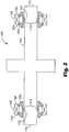
- the system 100 includes a horn 110 having a predetermined resonant frequency.
- Typical horns 110 that are commercially available have a resonant frequency (for an excitable vibration mode) of about 20,000 or 40,000 cycles per second (Hertz or Hz), though other resonant frequencies can be used.
- the horn 110 illustrated is rotary horn, though other types of horns, such as linear horns, can be used (such as 610 in FIG. 6 ).
- the horn 110 is coupled to mounting members 120, 130.
- the mounting members 120, 130 have an excitable resonant frequency that is about the same as the resonant frequency of the horn 110, as will be discussed hereinafter. Typically, horns have a resonant frequency of 20,000 or 40,000 Hertz.
- the mounting 120, 130 members have an inner portion 122, 132 and an outer surface 124, 134.
- the inner potion 122, 132 is coupled to the horn 110 at or near the nodal region 112 (as illustrated in Figures 1 and 2 ) of the horn 110.
- the nodal region 912 of the horn 910 is where the amplitude of lateral (or radial) displacement (curve D") during resonant vibration is at or near a maximum and the longitudinal displacement (transverse to the lateral displacement) is at or near a minimum.
- the maximum D max amplitude occurs in a direction perpendicular to the center (longitudinal or rotational) axis of the horn.
- the maximum amplitude occurs in a direction perpendicular to the longitudinal axis of the horn.
- the inner portion 122 of the mounting member 120 is coupled to the horn 110 at the nodal region 112. While it is typical to couple the mounting member 120 to the horn 110 at the position where the horn 110 has a maximum radial displacement, this point is sometimes difficult to locate precisely. It is typical to couple the mounting member 122 in the nodal region 112 where the radial displacement is at least 75% of the maximum amplitude, and more typically to couple the mounting member 120 where the radial displacement is at least 95% of the maximum amplitude. Coupled means that the respective elements are linked or connected together, but not necessarily in direct physical contact. For example, a membrane or sleeve of material could be positioned between the horn and the mounting member to reduced relative movement between the elements.
- the system 100 (of Figure 1 ) includes a rotary horn 110 and also includes two mounting members 120, 130.
- the horn has two nodal regions 112 (one of which is illustrated), which are typically located a one-half wavelength from each end of the horn 110.
- the mounting members 120, 130 are coupled to the horn 110 at the nodal region 112.
- the mounting members 120, 130 cooperate with bearing members 140, 150 to allow the horn 110 to rotate freely.
- the outer surface 124, 134 of the each mounting member 120, 130 is coupled to its respective bearing member 140, 150.
- One type of bearing member that can be used with the invention of the present disclosure is a needle roller bearing with an inner ring, such as model NA4924, available from INA Bearing Company.
- An advantage the example embodiment illustrated is that the outer bearing surface 124, 134 has a low vibrational amplitude, which can be zero for a mounting member having a resonant frequency matching the resonant frequency of the horn.
- the low amplitude of vibration of the outer bearing surface 124, 134 of the mounting member 120, 130 allows the outer bearing surface 124, 134 to be clamped or fixtured.
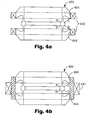
- a mounting member 420 is shown coupled to a pair of bearings 440.
- Each bearing 440 is coupled to a respective portion of the outer bearing surface 424 of the mounting member 420.
- the mounting member 420 is coupled to a single bearing 441.
- a coupling member 443, in this case a ring, is located between the outer bearing surface 424 and the bearing 441.
- the coupling member is press-fitted onto the mounting member and the bearing is mounted on the coupling member.
- the examples shown are not meant to be an exhaustive listing, but illustrate the potential for the use of various bearings coupled to the mounting member.
- One applying ordinary skill in the art will appreciate that other alternative embodiments can be used, and that the invention of the present disclosure allows an expanded selection of bearing arrangements. For example, when multiple bearing surfaces are present, each surface can be at a different distance from the horn surface, and different types of bearings can be used at each bearing surface.
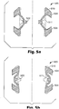
- FIG. 5a-b the cross-sectional view of a mounting member 520 having a natural resonant frequency of 20,000 Hertz illustrates the behavior of a low vibrational amplitude at the outer bearing surface 524.
- Figure 5a shows vibration in the inward direction (towards the horn) and
- Figure 5b shows vibration in the outward direction.
- the unexcited position 511 of the mounting member 520 is also illustrated.
- the displacement of the inner portion 522 of the mounting member 520 is much greater than the displacement of the outer bearing surface 524.
- the displacement of the outer bearing surface 524 is up to 10 percent of the displacement of the inner portion 522, though it can be greater.
- the displacement of the outer bearing surface 524 is up to 2 percent of the displacement of the inner portion 522.
- the displacement of the inner portion 522 typically is the same as the radial displacement of the horn nodal region (not shown) to which the inner potion 522 is coupled.
- the mounting member has an antinode at 522 and a node at 524.
- the system 600 is a plunge welding system and includes a horn/booster arrangement 605.
- the system 600 includes a converter 613 for exciting the horn/booster arrangement 605 to vibrate at the natural frequency of the horn 610, which is typically 20,00 or 40,000 Hertz, though other frequencies can be used, as is appreciated by application of ordinary skill in the art.
- the booster 614 is coupled to a mounting member 620, which has a natural resonant frequency about the same as the natural resonant frequency of the horn 610 and booster 614.
- the mounting member 620 is coupled to the horn/booster arrangement 605 at a nodal region 612, which is typically located on the booster 614 section of the arrangement, though it can be located on the horn 610.
- the mounting member 620 includes an inner portion 622 that is coupled to the nodal region 612 and an outer surface 624 that is coupled to a holding member 640, for example, a plate or fixture.
- the holding member 640 typically moves with the horn/booster arrangement 605 as the horn 610 is plunged to weld a part 606. The selection of the holding member depends on the particular conditions of use, and selection of a holding member or an equivalent is with application of ordinary skill in the art.
- the mounting member includes an inner portion 322 and an outer bearing surface 324.
- the inner portion 322 is coupled to a horn (not shown) in its nodal region.
- the mounting member 320 is designed to have a natural resonant frequency at about the same (predetermined) frequency as the horn to which it is coupled.
- the natural frequency of the mounting member 320 has an excitable mode such that the inner portion 322 moves with the radial displacement of the horn in the nodal region.
- the vibrational mode shape is shown in Figures 5a-b . All other excitable modes (at the horn frequency), other than the one described, of the mounting member 320 must be spaced away from the operating frequency.
- each mounting member 320 can be a unitary piece that can be shrink fitted on the horn, which is accomplished by techniques within the ordinary skill of one in the art.
- the shrink fit interference is about 0.001 to 0.0015 inches (0.0254 mm to 0.0381 mm) per 1.0 inch (25.4 mm) of horn diameter.
- the outer bearing surface 324 can be machined for concentricity and run out requirements of the system.
- the mounting member can also be made from multiple parts that cooperate to form a structure with a predetermined resonant frequency.
- an advantage of the example embodiment unitary mounting member previously discussed is that it can be made of a unitary structure. While it is possible to make the mounting member from more than one piece, a unitary structure reduces the number of components, along with other advantages that are appreciated by one of ordinary skill in the art.
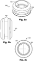
- a mounting member 820 of the present disclosure made out of single piece material.
- the material used is generally aluminum, steel, titanium, or brass.
- the mounting member 820 can be visualized and modeled using simple geometric elements.
- the mounting member has a circular mounting surface AB, a flexible cylinder QR, and outer surfaces EF and GH.
- the natural resonant frequency of the mounting member can be adjusted or tuned by varying the variables in the design, for example, the thickness of flexible cylinder, span length QR, diameters of surfaces PQ (RS) and EF (GH), central mass ACDB, and material properties, such as Young's modulus and/or density.
- the particular frequency at which the horn will resonate in the mode described will depend on its particular application and operating environment. Any particular configuration can be designed and validated using Finite Element Analysis, such as PROMECHANICA from Parametric Tech. Inc., to yield similar results.
- the mounting member 820 includes a base element 821, a pair of flanges 823 extending outwardly from the base element 821, and a mount element 825 extending inwardly towards a horn to which the mounting member 820 is coupled.
- the flanges 823 define an exterior bearing surface 824 that is coupled to a bearing (not shown).
- the base element 821 defines an interior bearing surface 822 that is coupled to a nodal region on the horn. When the interior bearing surface 822 is excited at about its natural resonant frequency, it vibrates at a maximum amplitude, and is an anti-nodal point on the mounting member 820.
- the exterior bearing surface 824 is a nodal point or region and has a low or zero vibrational amplitude.
- the motion of the exterior bearing surface 824 is less than 15 percent of the interior bearing surface 822, and more typically, is less than 2 percent of the interior bearing surface 822.
- the flanges 823 extending outwardly from the base element 821 may be perpendicular (line L-L) or at an angle (as is illustrated in Figure 7 ).
- the angle at which the flanges 823 extend is chosen to suit the particular use of the mounting member and is within the ordinary skill of one in the art.
- the exterior bearing surface 824 is generally parallel to the interior bearing surface 822 of the base element 821, which is typically oriented parallel to the surface of the horn to which it is coupled.
- FIG. 7 a cross-section of an example embodiment of a mounting member 720 that was built and tested is shown.
- the mounting member 720 was made of 4140-4150 steel, though other suitable materials can be used, for example, aluminum, titanium, or brass.
- the mounting member 720 is a solid of revolution (around centerline C"-C") of the cross-section illustrated.
- the diameter of surface A' B' is 3 in.
- diameter of P' Q' is 3.5 in.
- diameter of C'D' is 3.7 inches (93.98 mm)
- diameter of E' F' (G' H') is 4.9 (124.5 mm) inches.
- the dimension A' B', P'S', E'H' and F'G' are 0.3 (7.62 mm), 2.80 (71.12 mm), 1.95(49.53 mm), and 0.85 (21.59 mm) inches respectively.
- the natural frequency of the desired excitable mode of the mounting member 720 (as shown in Figure 5 ) was determined to be 20,054 Hz.
- a 0.005 inch (0.127 mm) interference was used to shrink fit the mounting member on the horn (diameter 3 inches) resulting in the diameter of surface A' B' being 2.995 (76.073) inches.
- the corner radius R" at each of the outer flange corners 745 is 0.125 inches (3.175 mm).
- the corner radius R''' at each of the inner flange corners 746 is 0.125 inches (3.175 mm).
- the flanges extend at an angle ⁇ of 55 degrees from the centerline C"-C".
- the mounting member 720 can also include a stop member 731, in this case a shoulder portion, protruding from the outer bearing surface 724. The stop member 731 assists in locating and securing a bearing or coupling member coupled to the mounting member.
- Table 1 Frequency: 20,010 Hz Booster 1.5 Gain Booster 2.0 Gain Power Draw from System in Air Without Nodal Mounts 250 Watts 400 Watts Power draw in air With Nodal Mounts 275 Watts 450 Watts Input to the horn 0.001 inches (0.0254 mm) 0.00134 inches (0.03404 mm) Radial amplitude at AB 0.0003 inches (0.00762 mm) 0.0004 inches (0.01016 mm) Radial amplitude at EF (GH) 0.00002 inches (0.000508 mm) 0.00003 inches (0.000762 mm)
- the mounting member of the present disclosure can be used to mount a horn into an ultrasonic welding system.
- a horn having a predetermined resonant frequency is provided.
- the horn has a resonant frequency of 20,000 or 40,000 Hertz, though other resonant frequencies are possible.
- a mounting member (or mount) having a resonant frequency at about the same resonant frequency as the horn is coupled or attached to a nodal region on the horn.
- a linear horn such as the type used in plunge welding
- a single mounting member is typically sufficient.
- a horn having more than one nodal region such as a rotary horn
- a mounting member is attached or coupled to each nodal region of the horn.
- the mounting member is a solid of rotation, and is attached directly to the horn using a shrink fit.
- an inner portion of the mounting member which is a typically an anti-nodal region for the mounting member, is shrink fitted directly onto the horn at the horn nodal region.
- the mounting member also includes an outer bearing surface or surfaces.
- the outer bearing surface which is generally a nodal region for the mounting member, can be coupled or attached to a bearing, which in turn is integrated into the system to allow the horn to move.
- the bearing(s) allow the horn to rotate during use.
- the bearing allows the horn to index against and away from the part or surface to be welded.
Claims (18)
- Ein System zur Ultraschallfertigung, das aufweist:ein rotierendes Ultraschallhorn (110) mit einer Resonanz bei einer vorgegebenen Frequenz, undeine Halterung (120, 130), die an einem Punkt (112), an dem das rotierende Ultraschallhorn (110) einen Knoten bei der vorgegebenen Frequenz aufweist, an das rotierende Ultraschallhorn (110) gekoppelt ist, dadurch gekennzeichnet, dass die Halterung eine Resonanz bei etwa der vorgegebenen Frequenz aufweist.
- Das System nach Anspruch 1, wobei die Halterung ein Rotatationskörper mit einer inneren Lagerfläche ist.
- Das System nach Anspruch 2, wobei das rotierende Ultraschallhorn direkt an die innere Lagerfläche gekoppelt ist.
- Das System nach Anspruch 3, wobei die Halterung mit dem rotierenden Ultraschallhorn durch Schrumpfpassung verbunden ist.
- Das System nach Anspruch 2, wobei die Halterung ein Basiselement, ein Paar Flansche, das sich von dem Basiselement nach außen erstreckt, und ein Halterungselement aufweist, das sich von dem Basiselement nach innen erstreckt.
- Das System nach Anspruch 5, wobei die Flansche eine äußere Lagerfläche aufweisen, die ein Knoten bei der vorgegebenen Frequenz ist.
- Das System nach Anspruch 6, wobei die Bewegung der äußeren Lagerfläche weniger als zwei Prozent der Bewegung einer inneren Lagerfläche beträgt, wenn das Halterungselement bei der vorgegebenen Frequenz angetrieben wird.
- Das System nach Anspruch 1, wobei die Halterung (120, 130) aufweist:ein ringförmiges Basiselement (821), das um das rotierende Ultraschallhorn (110) herum positioniert ist;ein Paar Flansche (823), das sich von dem Basiselement (821) nach außen erstreckt und eine äußere Lagerfläche (824) definiert; undein Horneingriffselement, das sich von dem Basiselement (821) nach innen erstreckt und eine innere Hornlagerfläche (822) definiert,wobei die äußere Lagerfläche (824) ein Knoten der Halterung ist, wenn die innere Lagerfläche (822) bei der vorgegebenen Frequenz durch das rotierende Ultraschallhorn (110) angetrieben wird.
- Das System nach Anspruch 8, wobei die Bewegung der äußeren Lagerfläche weniger als zwei Prozent der Bewegung der inneren Lagerfläche beträgt, wenn das Halterungselement bei der vorgegebenen Frequenz angetrieben wird.
- Das System nach Anspruch 9, wobei sich die Flansche in einem anderen Winkel als senkrecht von dem Basiselement erstrecken.
- Das System nach Anspruch 10, wobei die äußeren Lagerflächen im Allgemeinen parallel zu dem Basiselement sind.
- Ein Verfahren zum Montieren eines Ultraschallhorns (110), das aufweist:
Bereitstellen eines rotierenden Ultraschallhorns (110) mit einer Resonanz bei einer vorgegebenen Frequenz, und Anbringen einer Halterung (120, 130) an dem rotierenden Ultraschallhorn (110) an einem Punkt (112), an dem das rotierende Ultraschallhorn (110) einen Knoten bei der vorgegebenen Frequenz aufweist, dadurch gekennzeichnet, dass die Halterung eine Resonanz bei etwa der vorgegebenen Frequenz aufweist. - Das Verfahren nach Anspruch 12, wobei die Halterung ein Rotationskörper mit einer inneren Lagerfläche ist.
- Das Verfahren nach Anspruch 13, wobei die Halterung an dem rotierenden Ultraschallhorn derart befestigt wird, dass das rotierende Ultraschallhorn in Kontakt mit der inneren Lagerfläche ist.
- Das Verfahren nach Anspruch 14, wobei die Halterung durch Schrumpfpassung an dem rotierenden Ultraschallhorn angebracht wird.
- Das Verfahren nach Anspruch 13, wobei die Halterung ein Basiselement, ein Paar Flansche, das sich von der Basis nach außen erstreckt, und ein Halterungselement aufweist, das sich von der Basis nach innen erstreckt.
- Das Verfahren nach Anspruch 16, wobei die Flansche eine äußere Lagerfläche aufweisen, die ein Knoten bei der vorgegebenen Frequenz ist.
- Das Verfahren nach Anspruch 16, wobei die Bewegung der äußeren Lagerfläche weniger als zwei Prozent der Bewegung der inneren Lagerfläche beträgt, wenn das Halterungselement bei der vorgegebenen Frequenz angetrieben wird.
Applications Claiming Priority (2)
| Application Number | Priority Date | Filing Date | Title |
|---|---|---|---|
| US10/461,118 US6786384B1 (en) | 2003-06-13 | 2003-06-13 | Ultrasonic horn mount |
| PCT/US2004/012334 WO2005002746A2 (en) | 2003-06-13 | 2004-04-22 | Ultrasonic horn mount |
Publications (2)
| Publication Number | Publication Date |
|---|---|
| EP1633497A2 EP1633497A2 (de) | 2006-03-15 |
| EP1633497B1 true EP1633497B1 (de) | 2020-12-02 |
Family
ID=32927741
Family Applications (1)
| Application Number | Title | Priority Date | Filing Date |
|---|---|---|---|
| EP04750432.9A Expired - Lifetime EP1633497B1 (de) | 2003-06-13 | 2004-04-22 | Halterung für ein ultraschallhorn |
Country Status (7)
| Country | Link |
|---|---|
| US (1) | US6786384B1 (de) |
| EP (1) | EP1633497B1 (de) |
| JP (1) | JP4755102B2 (de) |
| KR (1) | KR101135808B1 (de) |
| BR (1) | BRPI0411284B1 (de) |
| MX (1) | MXPA05013527A (de) |
| WO (1) | WO2005002746A2 (de) |
Families Citing this family (18)
| Publication number | Priority date | Publication date | Assignee | Title |
|---|---|---|---|---|
| US7243894B2 (en) * | 2002-02-15 | 2007-07-17 | 3M Innovative Properties Company | Mount for vibratory elements |
| JP2008526514A (ja) * | 2005-01-03 | 2008-07-24 | スリーエム イノベイティブ プロパティズ カンパニー | 超音波溶接システムのホーンとアンビルとの間の隙間を制御する方法および装置 |
| DK1866104T3 (da) | 2005-03-23 | 2013-10-28 | 3L Ludvigsen As | Roterende ultralydsforsegler |
| DE102005063230B3 (de) * | 2005-12-23 | 2007-07-05 | Herrmann Ultraschalltechnik Gmbh & Co. Kg | Vorrichtung zum Ultraschallbearbeiten eines Werkstücks |
| KR100804255B1 (ko) * | 2007-12-31 | 2008-02-18 | 서옥순 | 초음파 용착기의 혼 제조방법 |
| US7718022B2 (en) * | 2008-05-15 | 2010-05-18 | 3M Innovative Properties Company | Resonant nodal mount for linear ultrasonic horns |
| US8113258B2 (en) * | 2008-07-08 | 2012-02-14 | Sonics & Materials Inc. | Ultrasonic welding device |
| US8082966B2 (en) | 2010-03-12 | 2011-12-27 | Edison Welding Institute, Inc. | System for enhancing sonotrode performance in ultrasonic additive manufacturing applications |
| JP5878299B2 (ja) * | 2010-04-27 | 2016-03-08 | 株式会社アドウェルズ | 超音波振動切断装置 |
| DE102013103887A1 (de) | 2013-04-17 | 2014-10-23 | Schunk Sonosystems Gmbh | Ultraschallschweißvorrichtung |
| US20150210003A1 (en) | 2014-01-28 | 2015-07-30 | Frito-Lay Noth America, Inc. | Transverse Sonotrode Design for Ultrasonic Welding |
| KR101665873B1 (ko) * | 2015-06-03 | 2016-10-13 | 주식회사 포스코 | 용접장치 |
| JP2020006969A (ja) * | 2018-07-03 | 2020-01-16 | 株式会社イシダ | 超音波シールユニット |
| CN109318064B (zh) * | 2018-11-09 | 2023-05-26 | 河南理工大学 | 法兰盘具有双减振和双密封的超声平面磨削方法及系统 |
| DE102018132838A1 (de) | 2018-12-19 | 2020-06-25 | Herrmann Ultraschalltechnik Gmbh & Co. Kg | Ultraschallschweißanlage mit Halterung |
| DE102018132839A1 (de) * | 2018-12-19 | 2020-06-25 | Herrmann Ultraschalltechnik Gmbh & Co. Kg | Ultraschallschweißanlage mit Abstützelement |
| JP6757837B1 (ja) * | 2019-08-30 | 2020-09-23 | 株式会社高田工業所 | 超音波共振体の支持構造及び超音波振動加工装置 |
| DE102022109304A1 (de) * | 2022-04-14 | 2023-10-19 | Ms Ultraschall Technologie Gmbh | Rotationssonotrode |
Family Cites Families (24)
| Publication number | Priority date | Publication date | Assignee | Title |
|---|---|---|---|---|
| USRE25119E (en) * | 1956-10-04 | 1962-01-30 | rawding | |
| GB877966A (en) * | 1959-04-10 | 1961-09-20 | Aeroprojects Inc | Vibratory devices and supports therefor |
| US3350582A (en) * | 1965-01-13 | 1967-10-31 | Union Special Machine Co | Vibratory apparatus |
| US3772538A (en) * | 1973-01-08 | 1973-11-13 | Kane Corp Du | Center bolt type acoustic transducer |
| US4647336A (en) | 1985-03-08 | 1987-03-03 | Kimberly-Clark Corporation | Rebuildable support assembly |
| JPH086745B2 (ja) * | 1985-08-28 | 1996-01-29 | インガーソル・ランド・カンパニー | モノレ−ル・クレ−ン・キヤリツジ |
| JPH0248153A (ja) | 1988-08-04 | 1990-02-16 | Mitsubishi Electric Corp | 超音波振動体の支持装置 |
| GB9006989D0 (en) * | 1990-03-28 | 1990-05-23 | Atomic Energy Authority Uk | Sonochemical apparatus |
| GB9226932D0 (en) * | 1992-12-24 | 1993-02-17 | Molins Plc | Web cutting device |
| JP3276460B2 (ja) * | 1993-06-15 | 2002-04-22 | 株式会社富士通宮城エレクトロニクス | ワイヤボンディング装置 |
| US5443240A (en) | 1994-02-09 | 1995-08-22 | Branson Ultrasonics Corporation | Mounting means for vibration member |
| US5603445A (en) * | 1994-02-24 | 1997-02-18 | Hill; William H. | Ultrasonic wire bonder and transducer improvements |
| US5595328A (en) * | 1994-12-23 | 1997-01-21 | Kulicke And Soffa Investments, Inc. | Self isolating ultrasonic transducer |
| US5660679A (en) | 1995-01-31 | 1997-08-26 | Kimberly-Clark Worldwide, Inc. | Rotary sealing system |
| GB2299046A (en) * | 1995-03-21 | 1996-09-25 | Nestle Sa | Ultrasonic cutting device |
| JP3078231B2 (ja) | 1995-08-22 | 2000-08-21 | 株式会社アルテクス | 超音波振動接合装置 |
| US5772100A (en) | 1996-03-22 | 1998-06-30 | American Technology, Inc. | Ultrasonic welder with dynamic nodal horn support |
| US5976316A (en) | 1998-05-15 | 1999-11-02 | 3M Innovative Properties Company | Non-nodal mounting system for acoustic horn |
| US6059923A (en) * | 1998-09-18 | 2000-05-09 | 3M Innovative Properties Company | Rotary acoustic horn with sleeve |
| US6457626B1 (en) * | 2001-01-29 | 2002-10-01 | Branson Ultrasonics Corporation | Symmetric ultrasonic rotary horn |
| US6634539B2 (en) * | 2001-09-21 | 2003-10-21 | 3M Innovative Properties Company | Adjustable-gap rotary ultrasonic horn mounting apparatus and method for mounting |
| US6547903B1 (en) * | 2001-12-18 | 2003-04-15 | Kimberly-Clark Worldwide, Inc. | Rotary ultrasonic bonder or processor capable of high speed intermittent processing |
| US6613171B2 (en) * | 2001-12-18 | 2003-09-02 | Kimberly-Clark Worldwide, Inc. | Rotary ultrasonic bonder or processor capable of fixed gap operation |
| US7243894B2 (en) * | 2002-02-15 | 2007-07-17 | 3M Innovative Properties Company | Mount for vibratory elements |
-
2003
- 2003-06-13 US US10/461,118 patent/US6786384B1/en not_active Expired - Lifetime
-
2004
- 2004-04-22 KR KR1020057023968A patent/KR101135808B1/ko active IP Right Grant
- 2004-04-22 EP EP04750432.9A patent/EP1633497B1/de not_active Expired - Lifetime
- 2004-04-22 JP JP2006532448A patent/JP4755102B2/ja not_active Expired - Fee Related
- 2004-04-22 MX MXPA05013527A patent/MXPA05013527A/es not_active Application Discontinuation
- 2004-04-22 BR BRPI0411284-9A patent/BRPI0411284B1/pt active IP Right Grant
- 2004-04-22 WO PCT/US2004/012334 patent/WO2005002746A2/en active Application Filing
Non-Patent Citations (1)
| Title |
|---|
| None * |
Also Published As
| Publication number | Publication date |
|---|---|
| EP1633497A2 (de) | 2006-03-15 |
| BRPI0411284A (pt) | 2006-08-01 |
| MXPA05013527A (es) | 2006-04-05 |
| WO2005002746A3 (en) | 2005-05-06 |
| BRPI0411284B1 (pt) | 2018-03-06 |
| KR101135808B1 (ko) | 2012-04-16 |
| JP2007501706A (ja) | 2007-02-01 |
| JP4755102B2 (ja) | 2011-08-24 |
| US6786384B1 (en) | 2004-09-07 |
| KR20060021892A (ko) | 2006-03-08 |
| WO2005002746A2 (en) | 2005-01-13 |
Similar Documents
| Publication | Publication Date | Title |
|---|---|---|
| EP1633497B1 (de) | Halterung für ein ultraschallhorn | |
| US5976316A (en) | Non-nodal mounting system for acoustic horn | |
| JP4116570B2 (ja) | 振動要素のための装着システム及び装着システムを形成するための方法 | |
| US3955740A (en) | Vibratory seam welding apparatus | |
| US7718022B2 (en) | Resonant nodal mount for linear ultrasonic horns | |
| JP3796533B2 (ja) | 回転アコースティックホーン | |
| TW201728402A (zh) | 朗之萬型超音波振動器的振動激發方法及超音波加工方法與超音波傳遞方法 | |
| MXPA04005252A (es) | Cuerno ultrasonico giratorio de aislante rigido. | |
| JP2004529002A (ja) | 対称的な超音波回転ホーン | |
| WO2017082350A1 (ja) | ランジュバン型超音波振動子の縦・ねじり振動の励起方法 | |
| JP4740697B2 (ja) | 超音波振動切削装置 | |
| WO2023032487A1 (ja) | 超音波共振体の締結構造及び超音波加工装置 | |
| MXPA00011175A (es) | Sistema de montaje no nodal para cuerno acustico | |
| Heisel et al. | An optimized design of the bearing in machines for ultrasonic machining processes | |
| JP6554698B2 (ja) | 超音波複合振動装置 | |
| JPH02227175A (ja) | 超音波振動体支持構造 |
Legal Events
| Date | Code | Title | Description |
|---|---|---|---|
| PUAI | Public reference made under article 153(3) epc to a published international application that has entered the european phase |
Free format text: ORIGINAL CODE: 0009012 |
|
| 17P | Request for examination filed |
Effective date: 20051215 |
|
| AK | Designated contracting states |
Kind code of ref document: A2 Designated state(s): AT BE BG CH CY CZ DE DK EE ES FI FR GB GR HU IE IT LI LU MC NL PL PT RO SE SI SK TR |
|
| 17Q | First examination report despatched |
Effective date: 20060621 |
|
| DAX | Request for extension of the european patent (deleted) | ||
| STAA | Information on the status of an ep patent application or granted ep patent |
Free format text: STATUS: EXAMINATION IS IN PROGRESS |
|
| RIC1 | Information provided on ipc code assigned before grant |
Ipc: B29C 65/08 20060101ALI20200312BHEP Ipc: B29C 65/00 20060101ALI20200312BHEP Ipc: B23K 20/10 20060101ALI20200312BHEP Ipc: B06B 3/00 20060101AFI20200312BHEP |
|
| GRAP | Despatch of communication of intention to grant a patent |
Free format text: ORIGINAL CODE: EPIDOSNIGR1 |
|
| STAA | Information on the status of an ep patent application or granted ep patent |
Free format text: STATUS: GRANT OF PATENT IS INTENDED |
|
| INTG | Intention to grant announced |
Effective date: 20200612 |
|
| RIN1 | Information on inventor provided before grant (corrected) |
Inventor name: HAREGOPPA, GOPAL B. |
|
| GRAS | Grant fee paid |
Free format text: ORIGINAL CODE: EPIDOSNIGR3 |
|
| GRAA | (expected) grant |
Free format text: ORIGINAL CODE: 0009210 |
|
| STAA | Information on the status of an ep patent application or granted ep patent |
Free format text: STATUS: THE PATENT HAS BEEN GRANTED |
|
| REG | Reference to a national code |
Ref country code: DE Ref legal event code: R081 Ref document number: 602004054873 Country of ref document: DE Owner name: 3M INNOVATIVE PROPERTIES COMPANY, ST. PAUL, US Free format text: FORMER OWNER: 3M INNOVATIVE PROPERTIES CO., ST. PAUL, MINN., US |
|
| AK | Designated contracting states |
Kind code of ref document: B1 Designated state(s): AT BE BG CH CY CZ DE DK EE ES FI FR GB GR HU IE IT LI LU MC NL PL PT RO SE SI SK TR |
|
| REG | Reference to a national code |
Ref country code: GB Ref legal event code: FG4D |
|
| REG | Reference to a national code |
Ref country code: CH Ref legal event code: EP Ref country code: AT Ref legal event code: REF Ref document number: 1340327 Country of ref document: AT Kind code of ref document: T Effective date: 20201215 |
|
| REG | Reference to a national code |
Ref country code: DE Ref legal event code: R096 Ref document number: 602004054873 Country of ref document: DE |
|
| REG | Reference to a national code |
Ref country code: IE Ref legal event code: FG4D |
|
| PG25 | Lapsed in a contracting state [announced via postgrant information from national office to epo] |
Ref country code: FI Free format text: LAPSE BECAUSE OF FAILURE TO SUBMIT A TRANSLATION OF THE DESCRIPTION OR TO PAY THE FEE WITHIN THE PRESCRIBED TIME-LIMIT Effective date: 20201202 Ref country code: GR Free format text: LAPSE BECAUSE OF FAILURE TO SUBMIT A TRANSLATION OF THE DESCRIPTION OR TO PAY THE FEE WITHIN THE PRESCRIBED TIME-LIMIT Effective date: 20210303 |
|
| REG | Reference to a national code |
Ref country code: NL Ref legal event code: MP Effective date: 20201202 |
|
| REG | Reference to a national code |
Ref country code: AT Ref legal event code: MK05 Ref document number: 1340327 Country of ref document: AT Kind code of ref document: T Effective date: 20201202 |
|
| PG25 | Lapsed in a contracting state [announced via postgrant information from national office to epo] |
Ref country code: BG Free format text: LAPSE BECAUSE OF FAILURE TO SUBMIT A TRANSLATION OF THE DESCRIPTION OR TO PAY THE FEE WITHIN THE PRESCRIBED TIME-LIMIT Effective date: 20210302 Ref country code: SE Free format text: LAPSE BECAUSE OF FAILURE TO SUBMIT A TRANSLATION OF THE DESCRIPTION OR TO PAY THE FEE WITHIN THE PRESCRIBED TIME-LIMIT Effective date: 20201202 Ref country code: PL Free format text: LAPSE BECAUSE OF FAILURE TO SUBMIT A TRANSLATION OF THE DESCRIPTION OR TO PAY THE FEE WITHIN THE PRESCRIBED TIME-LIMIT Effective date: 20201202 |
|
| PG25 | Lapsed in a contracting state [announced via postgrant information from national office to epo] |
Ref country code: NL Free format text: LAPSE BECAUSE OF FAILURE TO SUBMIT A TRANSLATION OF THE DESCRIPTION OR TO PAY THE FEE WITHIN THE PRESCRIBED TIME-LIMIT Effective date: 20201202 |
|
| PG25 | Lapsed in a contracting state [announced via postgrant information from national office to epo] |
Ref country code: CZ Free format text: LAPSE BECAUSE OF FAILURE TO SUBMIT A TRANSLATION OF THE DESCRIPTION OR TO PAY THE FEE WITHIN THE PRESCRIBED TIME-LIMIT Effective date: 20201202 Ref country code: EE Free format text: LAPSE BECAUSE OF FAILURE TO SUBMIT A TRANSLATION OF THE DESCRIPTION OR TO PAY THE FEE WITHIN THE PRESCRIBED TIME-LIMIT Effective date: 20201202 Ref country code: PT Free format text: LAPSE BECAUSE OF FAILURE TO SUBMIT A TRANSLATION OF THE DESCRIPTION OR TO PAY THE FEE WITHIN THE PRESCRIBED TIME-LIMIT Effective date: 20210405 Ref country code: RO Free format text: LAPSE BECAUSE OF FAILURE TO SUBMIT A TRANSLATION OF THE DESCRIPTION OR TO PAY THE FEE WITHIN THE PRESCRIBED TIME-LIMIT Effective date: 20201202 Ref country code: SK Free format text: LAPSE BECAUSE OF FAILURE TO SUBMIT A TRANSLATION OF THE DESCRIPTION OR TO PAY THE FEE WITHIN THE PRESCRIBED TIME-LIMIT Effective date: 20201202 |
|
| PG25 | Lapsed in a contracting state [announced via postgrant information from national office to epo] |
Ref country code: AT Free format text: LAPSE BECAUSE OF FAILURE TO SUBMIT A TRANSLATION OF THE DESCRIPTION OR TO PAY THE FEE WITHIN THE PRESCRIBED TIME-LIMIT Effective date: 20201202 |
|
| REG | Reference to a national code |
Ref country code: DE Ref legal event code: R097 Ref document number: 602004054873 Country of ref document: DE |
|
| PLBE | No opposition filed within time limit |
Free format text: ORIGINAL CODE: 0009261 |
|
| STAA | Information on the status of an ep patent application or granted ep patent |
Free format text: STATUS: NO OPPOSITION FILED WITHIN TIME LIMIT |
|
| PG25 | Lapsed in a contracting state [announced via postgrant information from national office to epo] |
Ref country code: IT Free format text: LAPSE BECAUSE OF FAILURE TO SUBMIT A TRANSLATION OF THE DESCRIPTION OR TO PAY THE FEE WITHIN THE PRESCRIBED TIME-LIMIT Effective date: 20201202 |
|
| 26N | No opposition filed |
Effective date: 20210903 |
|
| PG25 | Lapsed in a contracting state [announced via postgrant information from national office to epo] |
Ref country code: DK Free format text: LAPSE BECAUSE OF FAILURE TO SUBMIT A TRANSLATION OF THE DESCRIPTION OR TO PAY THE FEE WITHIN THE PRESCRIBED TIME-LIMIT Effective date: 20201202 Ref country code: ES Free format text: LAPSE BECAUSE OF FAILURE TO SUBMIT A TRANSLATION OF THE DESCRIPTION OR TO PAY THE FEE WITHIN THE PRESCRIBED TIME-LIMIT Effective date: 20201202 Ref country code: MC Free format text: LAPSE BECAUSE OF FAILURE TO SUBMIT A TRANSLATION OF THE DESCRIPTION OR TO PAY THE FEE WITHIN THE PRESCRIBED TIME-LIMIT Effective date: 20201202 Ref country code: SI Free format text: LAPSE BECAUSE OF FAILURE TO SUBMIT A TRANSLATION OF THE DESCRIPTION OR TO PAY THE FEE WITHIN THE PRESCRIBED TIME-LIMIT Effective date: 20201202 |
|
| PG25 | Lapsed in a contracting state [announced via postgrant information from national office to epo] |
Ref country code: LU Free format text: LAPSE BECAUSE OF NON-PAYMENT OF DUE FEES Effective date: 20210422 |
|
| REG | Reference to a national code |
Ref country code: BE Ref legal event code: MM Effective date: 20210430 |
|
| PG25 | Lapsed in a contracting state [announced via postgrant information from national office to epo] |
Ref country code: LI Free format text: LAPSE BECAUSE OF NON-PAYMENT OF DUE FEES Effective date: 20210430 Ref country code: CH Free format text: LAPSE BECAUSE OF NON-PAYMENT OF DUE FEES Effective date: 20210430 Ref country code: FR Free format text: LAPSE BECAUSE OF NON-PAYMENT OF DUE FEES Effective date: 20210430 |
|
| PG25 | Lapsed in a contracting state [announced via postgrant information from national office to epo] |
Ref country code: IE Free format text: LAPSE BECAUSE OF NON-PAYMENT OF DUE FEES Effective date: 20210422 |
|
| PGFP | Annual fee paid to national office [announced via postgrant information from national office to epo] |
Ref country code: GB Payment date: 20220323 Year of fee payment: 19 |
|
| PG25 | Lapsed in a contracting state [announced via postgrant information from national office to epo] |
Ref country code: BE Free format text: LAPSE BECAUSE OF NON-PAYMENT OF DUE FEES Effective date: 20210430 |
|
| PGFP | Annual fee paid to national office [announced via postgrant information from national office to epo] |
Ref country code: DE Payment date: 20220322 Year of fee payment: 19 |
|
| PG25 | Lapsed in a contracting state [announced via postgrant information from national office to epo] |
Ref country code: HU Free format text: LAPSE BECAUSE OF FAILURE TO SUBMIT A TRANSLATION OF THE DESCRIPTION OR TO PAY THE FEE WITHIN THE PRESCRIBED TIME-LIMIT; INVALID AB INITIO Effective date: 20040422 Ref country code: CY Free format text: LAPSE BECAUSE OF FAILURE TO SUBMIT A TRANSLATION OF THE DESCRIPTION OR TO PAY THE FEE WITHIN THE PRESCRIBED TIME-LIMIT Effective date: 20201202 |
|
| REG | Reference to a national code |
Ref country code: DE Ref legal event code: R119 Ref document number: 602004054873 Country of ref document: DE |
|
| GBPC | Gb: european patent ceased through non-payment of renewal fee |
Effective date: 20230422 |
|
| PG25 | Lapsed in a contracting state [announced via postgrant information from national office to epo] |
Ref country code: GB Free format text: LAPSE BECAUSE OF NON-PAYMENT OF DUE FEES Effective date: 20230422 |
|
| PG25 | Lapsed in a contracting state [announced via postgrant information from national office to epo] |
Ref country code: GB Free format text: LAPSE BECAUSE OF NON-PAYMENT OF DUE FEES Effective date: 20230422 Ref country code: DE Free format text: LAPSE BECAUSE OF NON-PAYMENT OF DUE FEES Effective date: 20231103 |