EP1632802B1 - Zoom lens and imaging apparatus - Google Patents
Zoom lens and imaging apparatus Download PDFInfo
- Publication number
- EP1632802B1 EP1632802B1 EP05291762A EP05291762A EP1632802B1 EP 1632802 B1 EP1632802 B1 EP 1632802B1 EP 05291762 A EP05291762 A EP 05291762A EP 05291762 A EP05291762 A EP 05291762A EP 1632802 B1 EP1632802 B1 EP 1632802B1
- Authority
- EP
- European Patent Office
- Prior art keywords
- group
- lenses
- zoom lens
- denotes
- blur compensation
- Prior art date
- Legal status (The legal status is an assumption and is not a legal conclusion. Google has not performed a legal analysis and makes no representation as to the accuracy of the status listed.)
- Not-in-force
Links
- 238000003384 imaging method Methods 0.000 title claims description 66
- 230000003287 optical effect Effects 0.000 claims description 31
- 238000005452 bending Methods 0.000 claims description 5
- 230000004075 alteration Effects 0.000 description 31
- 201000009310 astigmatism Diseases 0.000 description 12
- 150000001875 compounds Chemical class 0.000 description 9
- 230000014509 gene expression Effects 0.000 description 6
- 230000003595 spectral effect Effects 0.000 description 5
- 238000006073 displacement reaction Methods 0.000 description 4
- 238000006243 chemical reaction Methods 0.000 description 3
- 230000001419 dependent effect Effects 0.000 description 3
- 238000010586 diagram Methods 0.000 description 2
- 239000004973 liquid crystal related substance Substances 0.000 description 2
- 230000015572 biosynthetic process Effects 0.000 description 1
- 239000002131 composite material Substances 0.000 description 1
- 230000006835 compression Effects 0.000 description 1
- 238000007906 compression Methods 0.000 description 1
- 230000006837 decompression Effects 0.000 description 1
- 230000000881 depressing effect Effects 0.000 description 1
- 230000000994 depressogenic effect Effects 0.000 description 1
- 230000001747 exhibiting effect Effects 0.000 description 1
- 239000011521 glass Substances 0.000 description 1
- 238000004519 manufacturing process Methods 0.000 description 1
- 239000000463 material Substances 0.000 description 1
- 239000004065 semiconductor Substances 0.000 description 1
Images


Classifications
-
- G—PHYSICS
- G02—OPTICS
- G02B—OPTICAL ELEMENTS, SYSTEMS OR APPARATUS
- G02B15/00—Optical objectives with means for varying the magnification
- G02B15/14—Optical objectives with means for varying the magnification by axial movement of one or more lenses or groups of lenses relative to the image plane for continuously varying the equivalent focal length of the objective
- G02B15/16—Optical objectives with means for varying the magnification by axial movement of one or more lenses or groups of lenses relative to the image plane for continuously varying the equivalent focal length of the objective with interdependent non-linearly related movements between one lens or lens group, and another lens or lens group
- G02B15/163—Optical objectives with means for varying the magnification by axial movement of one or more lenses or groups of lenses relative to the image plane for continuously varying the equivalent focal length of the objective with interdependent non-linearly related movements between one lens or lens group, and another lens or lens group having a first movable lens or lens group and a second movable lens or lens group, both in front of a fixed lens or lens group
- G02B15/167—Optical objectives with means for varying the magnification by axial movement of one or more lenses or groups of lenses relative to the image plane for continuously varying the equivalent focal length of the objective with interdependent non-linearly related movements between one lens or lens group, and another lens or lens group having a first movable lens or lens group and a second movable lens or lens group, both in front of a fixed lens or lens group having an additional fixed front lens or group of lenses
- G02B15/173—Optical objectives with means for varying the magnification by axial movement of one or more lenses or groups of lenses relative to the image plane for continuously varying the equivalent focal length of the objective with interdependent non-linearly related movements between one lens or lens group, and another lens or lens group having a first movable lens or lens group and a second movable lens or lens group, both in front of a fixed lens or lens group having an additional fixed front lens or group of lenses arranged +-+
-
- G—PHYSICS
- G02—OPTICS
- G02B—OPTICAL ELEMENTS, SYSTEMS OR APPARATUS
- G02B13/00—Optical objectives specially designed for the purposes specified below
- G02B13/18—Optical objectives specially designed for the purposes specified below with lenses having one or more non-spherical faces, e.g. for reducing geometrical aberration
-
- G—PHYSICS
- G02—OPTICS
- G02B—OPTICAL ELEMENTS, SYSTEMS OR APPARATUS
- G02B15/00—Optical objectives with means for varying the magnification
- G02B15/14—Optical objectives with means for varying the magnification by axial movement of one or more lenses or groups of lenses relative to the image plane for continuously varying the equivalent focal length of the objective
- G02B15/145—Optical objectives with means for varying the magnification by axial movement of one or more lenses or groups of lenses relative to the image plane for continuously varying the equivalent focal length of the objective having five groups only
- G02B15/1451—Optical objectives with means for varying the magnification by axial movement of one or more lenses or groups of lenses relative to the image plane for continuously varying the equivalent focal length of the objective having five groups only the first group being positive
- G02B15/145113—Optical objectives with means for varying the magnification by axial movement of one or more lenses or groups of lenses relative to the image plane for continuously varying the equivalent focal length of the objective having five groups only the first group being positive arranged +-++-
-
- G—PHYSICS
- G02—OPTICS
- G02B—OPTICAL ELEMENTS, SYSTEMS OR APPARATUS
- G02B27/00—Optical systems or apparatus not provided for by any of the groups G02B1/00 - G02B26/00, G02B30/00
- G02B27/64—Imaging systems using optical elements for stabilisation of the lateral and angular position of the image
- G02B27/646—Imaging systems using optical elements for stabilisation of the lateral and angular position of the image compensating for small deviations, e.g. due to vibration or shake
-
- H—ELECTRICITY
- H04—ELECTRIC COMMUNICATION TECHNIQUE
- H04N—PICTORIAL COMMUNICATION, e.g. TELEVISION
- H04N23/00—Cameras or camera modules comprising electronic image sensors; Control thereof
- H04N23/50—Constructional details
- H04N23/55—Optical parts specially adapted for electronic image sensors; Mounting thereof
Definitions
- the present invention relates to a zoom lens having a camera shake compensation function, that is, a function of correcting a blur in a constructed image derived from a vibration of a camera, and an imaging apparatus employing the zoom lens. More particularly, the present invention is concerned with a zoom lens that is compact enough to be preferably adopted as an imaging optical system to be included in a digital still camera, a digital video camera, or any other digital input/output equipment, that highly precisely varies a power, and that has a camera shake compensation function, and an imaging apparatus employing the zoom lens.
- a zoom lens that is compact enough to be preferably adopted as an imaging optical system to be included in a digital still camera, a digital video camera, or any other digital input/output equipment, that highly precisely varies a power, and that has a camera shake compensation function, and an imaging apparatus employing the zoom lens.
- the digital still camera and other types of imaging apparatuses employing a solid-state imaging device have prevailed. Higher image quality is demanded along with the prevalence of the digital still camera.
- the digital still camera employing an imaging device which offers a large number of pixels is requested to include an imaging lens or especially a zoom lens that enjoys perfect image formation and suits the solid-state imaging device which offers a large number of pixels.
- a zoom lens that is especially compact in the direction of the depth thereof, that is, an incident optical-axis direction is in need.
- Japanese Unexamined Patent Publication JP 05 224160 describes a zoom lens including a first group of lenses that is positively refractive, a second group of lenses that is negatively refractive, a third group of lenses that is positively refractive, a fourth group of lenses that is positively refractive, a fifth group of lenses that includes a group of positive lenses and a group of negative lenses and that is negatively refractive as a whole.
- a camera shake is compensated by moving the group of negative lenses, which belongs to the fifth group of lenses, in directions perpendicular to the optical axis of the zoom lens.
- an optical system is bent by inserting a prism among lenses in attempts to downsize the optical system in an incident optical-axis direction.
- an optical system or a zoom lens described in JP 08 248318 has the optical axis thereof bent by disposing a prism among four groups of positive lenses, negative lenses, positive lenses, and positive lenses, and is thus downsized in the incident optical-axis direction.
- the zoom lens described in JP 05 224160 has so many lenses that the thickness in the direction of the depth of a camera, that is, an incident optical-axis direction is not reduced even with the lenses stored.
- the fifth group of lenses including the group of blur compensation lenses is a group of movable lenses that is moved in order to vary a power. Therefore, a mechanism for driving the group of blur compensation lenses is disposed outside a mechanism for moving the group of blur compensation lenses in optical-axis directions. This leads to an increase in the size in a radial direction of the portion of the camera in which the fifth group of lenses is incorporated.
- the leading lens and a reflecting member are too large to attain a compact design.
- the present invention addresses the foregoing problems underlying the related arts.
- a zoom lens that is compact enough to be preferably adopted as imaging optical system to be included in a digital still camera, a digital video camera, or any other digital input/output equipment, that highly precisely varies a power, and that has a camera shake compensation function, and an imaging apparatus employing the zoom lens.
- the present invention is directed to a zoom lens according to claim 1 of the appended claims.
- the present invention is also directed to an imaging apparatus that includes a zoom lens according to claim 1 of the appended claims.
- a compact and high-performance zoom lens capable of compensating a camera shake.
- the employment of the zoom lens provides a compact and high-performance imaging apparatus capable of compensating a camera shake.
- a group of lenses located at the end of an object space is held stationary in optical-axis directions during variation of the power of the zoom lens.
- a reflecting member is included for bending the optical axis substantially 90°.
- the imaging apparatus may be downsized in the direction of the depth thereof, that is, an incident optical-axis direction in which light is incident on the zoom lens.
- the zoom lens has a first group of lenses which is positively refractive, a second group of lenses which is negatively refractive, a third group of lenses which is positively refractive, a fourth group of lenses which is positively refractive, and a fifth group of lenses, which is negatively refractive, juxtaposed in that order from the end of an object space.
- the fourth group of lenses is moved in optical-axis directions in order to focus the zoom lens for near-distance imaging. This results in a compact design.
- CR denotes a radius of curvature whose reciprocal is the curvature of the surface of a lens included in the group of blur compensation lenses and located at the end of the object space
- Ymax denotes a maximum height of an image converged on an imaging device
- ⁇ a denotes a power offered by the group of blur compensation lenses
- ⁇ b denotes a power offered by a group of lenses located more closely to an image plane than the group of blur compensation lenses
- a zoom lens in accordance with an embodiment of the present invention has a first group of lenses GR1 which is positively refractive, a second group of lenses GR2 which is negatively refractive, a third group of lenses GR3 which is positively refractive, a fourth group of lenses GR4 which is positively refractive, and a fifth group of lenses, which is negatively refractive, juxtaposed in that order from the end of an object space.
- the first group of lenses GR1, third group of lenses GR3, and fifth group of lenses GR5 are held stationary during variation of the power of the zoom lens.
- the second group of lenses GR2 is mainly moved in optical-axis directions in order to vary a power.
- the fourth group of lenses GR4 is moved in the optical-axis directions in order to compensate a displacement of an image plane occurring during variation of the power of the zoom lens or focus the zoom lens for near-distance imaging.
- the fifth group of lenses GR5 includes a front group of lenses FG that is negatively refractive and a rear group of lenses RG that is positively refractive.
- the rear group of lenses RG that is positively refractive or part of the rear group of lenses RG (hereinafter, referred to as a group of blur compensation lenses) is moved in directions orthogonal to the optical axis in order to shift an image.
- the fifth group of lenses GR5 that is the last group of lenses includes the front group of lenses FG that is negatively refractive and the rear group of lenses RG that is positively refractive. Consequently, the front group of lenses FG pops light up and the rear group of lenses RG provides light analogous to light having passed through a telecentric system. Consequently, the first group of lenses GR1 or especially the leading lens G1 that is included in the first group of lenses and located at the end of an object space has the diameter thereof reduced. Eventually, the zoom lens becomes compact as a whole.
- the group of blur compensation lenses is disposed as a trailing group of lenses, a compact design and a reduced number of lenses are attained.
- the group of blur compensation lenses since the group of blur compensation lenses is disposed as a trailing group of lenses, the group of blur compensation lenses will not interfere with a group of movable lenses (for example, the second group of lenses GR2 or the fourth group of lenses GR4).
- the disposition of a mechanism for driving the group of blur compensation lenses will not increase the outer diameter of the zoom lens.
- a group of lenses that provides light analogous to light having passed through a telecentric system is moved in directions orthogonal to the optical axis in order to compensate a camera shake.
- Aberrations are therefore limited.
- high optical performance can be maintained without an increase in the number of lenses.
- a reflecting member for bending the optical axis of the zoom lens nearly 90° is included in the first group of lenses GR1 that is a group of stationary lenses.
- the depth of an imaging apparatus such as a digital still camera can be reduced, that is, the imaging apparatus can be thinned.
- the zoom lens in accordance with the embodiment of the present invention satisfies the condition expressed by the following formula (1): 0.002 ⁇ 1 / CR / Y ⁇ max ⁇ 0.05
- CR denotes a radius of curvature whose reciprocal is the curvature of the surface of the lens located at the object space-side end of the group of blur compensation lenses
- Ymax denotes the maximum height of an image converged on an imaging device.
- the formula (1) limits the radius of curvature, the reciprocal of which is the curvature of the surface of the lens located at the object space-side end of the group of blur compensation lenses, to a specific range. If the numerical value of an expression (1/CR)/Ymax falls below a lower limit specified in the formula (1), that is, if the radius of curvature whose reciprocal is the curvature of the surface of the lens located at the object space-side end of the group of blur compensation lenses falls below a value inferred from the formula (1), it is difficult to make the optical system compact.
- the zoom lens in accordance with the embodiment of the present invention satisfies the condition expressed by the following formula (2): 0.5 ⁇ 1 ⁇ ⁇ ⁇ a ⁇ ⁇ ⁇ b ⁇ 1.2 where ⁇ a denotes a power offered by the group of blur compensation lenses, and ⁇ b denotes a power offered by a group of lenses located more closely to an image plane than the group of blur compensation lenses is.
- the formula (2) limits a ratio of a magnitude of a shift made by an image to a magnitude of movement made by the group of blur compensation lenses, to a specific range. If the numerical value of an expression (1- ⁇ a) ⁇ b falls below a lower limit specified in the formula (2), the magnitude of movement made by the group of blur compensation lenses that causes an image to shift increases. This leads to an increase in the size of a driving system and hinders realization of a compact design. If the numerical value of the expression (1- ⁇ a) ⁇ b exceeds an upper limit specified in the formula (2), although the group of blur compensation lenses inches, an image shifts largely. This leads to a demand for highly precise control. Eventually, it becomes necessary to manufacture or assemble parts precisely and to control a detecting system and a driving system highly precisely. This results in a very expensive zoom lens.
- the reflecting member when a prism is adopted as the reflecting member for bending the optical axis, a glass material exhibiting a high refractive index is preferably adopted. Consequently, the reflecting member is downsized. This is advantageous in realizing a compact zoom lens.
- an ND filter or a liquid-crystal light adjustment device is employed instead of changing the diameter of an aperture stop so as to adjust an amount of light.
- electric signal processing is performed in order to compensate a color mismatch occurring during compensation of a camera shake. Consequently, a load imposed on lenses during compensation of a chromatic aberration is lightened, and the number of lenses is reduced. It becomes easy to design lenses.
- ⁇ denotes a half angle of view
- si denotes the i-th surface from the surface located at the end of an object space
- ri denotes a radius of curvature whose reciprocal is the curvature of the surface si
- di denotes a spacing between the i-th surface from the surface located at the end of the object space and the i+1-th surface
- ni denotes a refractive index by which the i-th lens affects a spectral line d (wavelength of 587.6 nm)
- vi denotes an Abbe number by which the i-th lens affects the spectral line d (wavelength of 587.6 nm).
- x denotes a distance in an optical-axis direction from the vertex of a lens
- y denotes a height in a direction perpendicular to the optical axis
- c denotes the paraxial curvature of a lens at the vertex of the lens
- ⁇ denotes a conical constant
- a i denotes an i-th-order aspherical coefficient.
- Fig. 1 shows the arrangement of lenses included in a zoom lens in accordance with a first embodiment of the present invention.
- the zoom lens has a first group of lenses GR1 which is positively refractive, a second group of lenses GR2 which is negatively refractive, a third group of lenses GR3 which is positively refractive, a fourth group of lenses GR4 which is positively refractive, and a fifth group of lenses GR5, which is negatively refractive, juxtaposed in that order from the end of an object space.
- the first group of lenses GR1 includes a negative lens G1, a rectangular prism G2 that bends the optical axis of the zoom lens 90°, and a positive lens G3 whose surfaces are aspheric surfaces.
- the second ground of lenses GR2 includes a negative lens G4, and a compound lens made up of a negative lens G5 and a positive lens G6.
- the third group of lenses GR3 is realized with a positive lens G7 whose surfaces are aspheric surfaces.
- the fourth group of lenses GR4 is realized with a compound lens made up of a positive lens G8 and a negative lens G9.
- the fifth group of lenses includes a front group of lenses FG realized with a negative lens G10 and a rear group of lenses RG realized with a positive lens G11.
- the rear group of lenses GR (group of blur compensation lenses) is moved in directions perpendicular to the optical axis in order to shift an image.
- the first group of lenses GR1, the third group of lenses GR3, and the fifth group of lenses GR5 are held stationary during variation of the power of the zoom lens.
- the second group of lenses GR2 is mainly moved in optical-axis directions in order to vary a power.
- the fourth group of lenses GR4 is moved in the optical-axis directions in order to compensate a displacement of an image plane occurring during variation of the power of the zoom lens or to focus the zoom lens for near-distance imaging.
- LPF denotes a low-pass filter interposed between the fifth group of lenses GR5 and the image plane IMG.
- an aperture stop IR is disposed near the image plane-side end of the third group of lenses GR3 and held stationary during variation of the power of the zoom lens.
- Table 1 lists numerical values concerning optical elements, which are concrete values adapted to the first embodiment, as part of the first numerical example.
- ASP signifies that a surface concerned is an aspheric surface
- INFINITY signifies that a surface concerned is a plane.
- an inter-surface spacing d6 between the first group of lenses GR1 and the second group of lenses GR2, an inter-surface spacing d11 between the second group of lenses GR2 and the third group of lenses GR3, an inter-surface spacing d14 between the aperture stop IR and the fourth group of lenses GR4, and an inter-surface spacing d17 between the fourth group of lenses GR4 and the fifth group of lenses GR5 are variable for variation of a power.
- Table 2 lists as part of the first numerical example the values of the inter-surface spacings d6, d11, d14, and d17 adapted to the first embodiment together with focal lengths, f-numbers, and half angles of views ⁇ , wherein the numerical values are measured with the groups of lenses moved to their wide-angle positions, their intermediate focal points located between their wide-angle positions and their telephoto positions, and their telephoto positions.
- Table 2 Focal length 6.52 10.95 18.54 f-number 3.60 3.88 4.63 ⁇ (degree) 30.54 18.29 10.86 d6 0.500 3.544 5.564 d11 5.564 2.520 0.500 d14 7.525 4.851 1.882 d17 1.300 3.974 6.943
- the surfaces s5 and s6 of the second lens G3 included in the first group of lenses GR1, the surfaces s12 and s13 of the positive lens G7 included in the third group of lenses GR3, and the object space-side surface s15 of the compound lens realizing the fourth group of lenses GR4 are aspheric surfaces.
- Table 3 lists as part of the first numerical example the fourth-order, sixth-order, eighth-order, and tenth-order aspherical coefficients for the surfaces s5, s6, s12, s13, and s15 together with conical constants ⁇ .
- Fig. 2 graphically shows aberrations, which occur with the groups of lenses moved to their wide-angle positions, on the basis of the first numerical example.
- Fig. 3 graphically shows the aberrations, which occur with the groups of lenses moved to their intermediate focal points between their wide-angle positions and their telephoto positions, on the basis of the first numerical example.
- Fig. 4 graphically shows the aberrations, which occur with the groups of lenses moved to their telephoto positions, on the basis of the first numerical example.
- spherical aberrations dependent on spectral lines d, C, and g respectively are indicated with a solid line, a dashed line, and a dot-dash line respectively with the axis of ordinates graduated in ratios to f-numbers measured with the aperture stop held open and with the axis of abscissas graduated in degrees of defocus.
- Astigmatisms occurring on a sagittal plane and a meridional plane respectively are indicated with a solid line and a dashed line respectively with the axis of ordinates graduated in image heights and the axis of abscissas graduated in focal lengths.
- a distortion is indicated with the axis of ordinates graduated in image heights and the axis of abscissas graduated in percentages.
- Fig. 5 shows the arrangement of lenses included in a zoom lens in accordance with a second embodiment of the present invention.
- the zoom lens has a first group of lenses GR1 which is positively refractive, a second group of lenses GR2 which is negatively refractive, a third group of lenses GR3 which is positively refractive, a fourth group of lenses GR4 which is positively refractive, and a fifth group of lenses, which is negatively refractive, juxtaposed in that order from the end of an object space.
- the first group of lenses GR1 includes a negative lens G1, a rectangular prism G2 that bends the optical axis of the zoom lens 90°, and a positive lens G3 whose surfaces are aspheric surfaces.
- the second group of lenses GR2 includes a negative lens G4, a compound lens made up of a negative lens G5 and a positive lens G6, and a negative lens G7.
- the third group of lenses G3 is realized with a positive lens G8 whose surfaces are aspheric surfaces.
- the fourth group of lenses GR4 is realized with a compound lens made up of a positive lens G9 whose object plane side has an aspheric surface, and a negative lens G10.
- the fifth group of lenses GR5 includes a front group of lenses FG realized with a negative lens G11, and a rear group of lenses RG including a positive lens G12 and a negative lens G13 whose surfaces are aspheric surfaces.
- a positive lens G12 (group of blue compensation lenses) that is part of the rear group of lenses RG is moved in directions perpendicular to the optical axis in order to shift an image.
- the first group of lenses GR1, the third group of lenses GR3, and the fifth group of lenses GR5 are held stationary during variation of the power of the zoom lens.
- the second group of lenses GR2 is mainly moved in optical-axis directions in order to vary a power.
- the fourth group of lenses GR4 is moved in the optical-axis directions in order to compensate a displacement of an image plane occurring during variation of the power of the zoom lens or focus the zoom lens for near-distance imaging.
- LPF denotes a low-pass filter interposed between the fifth group of lenses GR5 and the image plane IMG.
- an aperture stop IR is disposed near the image-plane side of the third group of lenses GR3, and held stationary during variation of the power of the zoom lens.
- Table 4 lists numerical values concerning optical elements as part a second numerical example, wherein the numerical values are concrete values adapted to the second embodiment.
- an inter-surface spacing d6 between the first group of lenses GR1 and the second group of lenses GR2, an inter-surface distance d13 between the second group of lenses GR2 and the third group of lenses GR3, an inter-surface distance d16 between the aperture stop IR and the fourth group of lenses Gr, and an inter-surface distance d19 between the fourth group of lenses GR4 and the fifth group of lenses GR5 are variable for variation of a power.
- Table 5 lists as part of the second numerical example the values of the inter-surface spacings d6, d13, d16, and d19 together with focal lengths, f-numbers, and half angles of view ⁇ , wherein the values of the inter-surface spacings are measured with the groups of lenses moved to their wide-angle positions, their intermediate focal points between their wide-angle positions and their telephoto positions, and their telephoto positions.
- Table 5 Focal length 6.88 12.72 33.01 f-number 3.60 3.79 4.53 ⁇ (degree) 30.06 16.36 6.39 d6 0.600 6.177 11.895 d13 11.865 6.288 0.570 d16 8.214 5.922 2.108 d19 1.500 3.792 7.606
- the surfaces s5 and s6 of the second lens G3 included in the first group of lenses GR1 are aspheric surfaces.
- the surfaces s14 and s15 of a positive lens G7 included in the third group of lenses GR3 are aspheric surfaces.
- Table 6 lists as part of the second numerical example the fourth-order, sixth-order, eight-order, and tenth-order aspherical coefficients for the surfaces s5, s6, s14, s15, s17, s24, and s25 together with conical constants ⁇ .
- Fig. 6 graphically shows aberrations, which occur with the groups of lenses moved to their wide-angle positions, on the basis of the second numerical example.
- Fig. 7 graphically shows aberrations, which occur with the groups of lenses moved to their intermediate focal points between their wide-angle positions and their telephoto positions, on the basis of the second numerical example.
- Fig. 8 graphically shows aberrations, which occur with the groups of lenses moved to their telephoto positions, on the basis of the second numerical example.
- spherical aberrations dependent on spectral lines d, C, and g are indicated with a solid line, a dashed line, and a dot-dash line respectively with the axis of ordinates graduated in ratios to f-numbers measured with the aperture stop left open and with the axis of abscissas graduated in degrees of defocus.
- Astigmatisms occurring on a sagittal plane and meridional plane respectively are indicated with a solid line and a dashed line respectively with the axis of ordinate graduated in image heights and with the axis of abscissas graduated in focal lengths.
- a distortion is indicated with the axis of ordinates graduated in image heights and the axis of abscissas graduated in percentages.
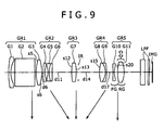
- Fig. 9 shows the arrangement of lenses included in a zoom lens in accordance with a third embodiment of the present invention.
- the zoom lens has a first group of lenses GR1 which is positively refractive, a second group of lenses GR2 which is negatively refractive, a third group of lenses GR3 which is positively refractive, a fourth group of lenses GR4 which is positively refractive, and a fifth group of lenses GR5, which is negatively refractive, juxtaposed in that order from the end of an object space.
- the first group of lenses GR1 includes a negative lens G1, a rectangular prism G2 that bends the optical axis of the zoom lens 90°, and a positive lens G3 whose surfaces are aspheric surfaces.
- the second group of lenses GR2 includes a negative lens G4, and a compound lens made up of a negative lens G5 and a positive lens G6.
- the third group of lenses GR3 is realized with a positive lens G7 whose surfaces are aspheric surfaces.
- the fourth group of lenses GR4 is realized with a compound lens made up of a positive lens G8 and a negative lens G9.
- the fifth group of lenses GR5 includes a front group of lenses FG realized with a negative lens G10 and a rear group of lenses RG realized with a positive lens G11 whose object space side has an aspheric surface.
- the positive lens G11 realizing the rear group of lenses RG (group of blur compensation lenses) is moved in directions perpendicular to the optical axis in order to shift an image.
- the first group of lenses GR1, the third group of lenses GR3, and the fifth group of lenses GR5 are held stationary during variation of the power of the zoom lens.
- the second group of lenses GR is mainly moved in optical-axis directions in order to vary the power of the zoom lens.
- the fourth group of lenses GR4 is moved in the optical-axis directions in order to compensate a displacement of an image plane occurring during variation of the power of the zoom lens or to focus the zoom lens for near-distance imaging.
- LPF denotes a low-pass filter interposed between the fifth group of lenses GR5 and the image plane IMG.
- an aperture stop IR is disposed near the image-plane side of the third group of lenses GR3 and is held stationary during variation of the power of the zoom lens.
- Table 7 lists as part of a third numerical example numerical values concerning optical elements that are concrete values adapted to the third embodiment.
- the inter-surface spacing d6 between the first group of lenses GR1 and the second group of lenses GR2, the inter-surface spacing d11 between the second group of lenses GR2 and the third group of lenses GR3, the inter-surface spacing d14 between the aperture stop IR and the fourth group of lenses GR4, and the inter-surface spacing d17 between the fourth group of lenses GR4 and the fifth group of lenses GR5 are variable for variation of the power of the zoom lens.
- Table 8 lists as part of the third numerical example the values of the inter-surface spacings d6, d11, d14, and d17 together with focal lengths, f-numbers, and half angles of view ⁇ , wherein the values of the inter-surface spacings are measured with the groups of lenses moved to their wide-angle positions, their intermediate focal points between their wide-angle positions and their telephoto positions, and their telephoto positions.
- Table 8 Focal length 6.00 10.08 17.07 f-number 3.60 3.83 4.53 ⁇ (degree) 32.63 12.65 6.02 d6 0.500 4.129 6.460 d11 6.577 2.948 0.617 d14 7.063 4.585 1.723 d17 1.905 4.383 7.245
- the surfaces s5 and s6 of the second lens G3 included in the first group of lenses GR1, the surfaces s12 and s13 of the positive lens G7 serving as the third group of lenses GR3, the object space-side surface s15 of the compound lens realizing the fourth group of lenses GR4, and the object space-side surface s20 of the positive lens G11 realizing the rear group of lenses RG belonging to the fifth group of lenses GR5 are aspheric surfaces.
- Table 9 lists as part of the third numerical example the fourth-order, sixth-order, eighth-order, and tenth-order aspherical coefficients for the surfaces s5, s6, s12, s13, s15, and s20 together with conical constants ⁇ .
- Fig. 10 graphically shows aberrations, which occur with the groups of lenses moved to their wide-angle positions, on the basis of the third numerical example.
- Fig. 11 graphically shows aberrations, which occur with the groups of lenses moved to their intermediate focal points between their wide-angle positions and their telephoto positions, on the basis of the third numerical example.
- Fig. 12 graphically shows aberrations, which occur with the groups of lenses moved to their telephoto positions, on the basis of the third numerical example.
- spherical aberrations dependent on spectral lines d, C, and g are indicated with a solid line, a dashed line, and a dot-dash line respectively with the axis of ordinates graduated in ratios to f-numbers measured with the aperture stop left open and with the axis of abscissas graduated in degrees of defocus.
- Astigmatisms occurring on a sagittal plane and a meridional plane respectively are indicated with a solid line and a dashed line respectively with the axis of ordinates graduated in image heights and the axis of abscissas graduated in focal lengths.
- a distortion is indicated with the axis of ordinates graduated in image heights and the axis of abscissas graduated in percentages.
- Table 10 lists the numerical values of the conditional expressions included in the formulae (1) and (2) which are calculated based on the first to third numerical examples.
- Table 10 Conditional expression First numerical example Second numerical example Third numerical example (1)(1/CR)Ymax 0.027 0.020 0.014 (2)(1- ⁇ a) ⁇ b 0.660 0.782 0.766
- the zoom lenses characterized by the first to third numerical examples satisfy the conditions expressed by the formulae (1) and (2).
- the drawings graphically showing aberrations, the aberrations occurring with the groups of lenses moved to their wide-angle positions, their intermediate focal points between their wide-angle positions and their telephoto positions, and their telephoto positions are compensated in a balanced manner.
- FIG. 13 is a block diagram showing an example of the configuration of a digital still camera in which the zoom lens in accordance with the present invention may be incorporated.
- a digital still camera 100 shown in Fig. 13 includes a camera block 10 responsible for imaging, a camera signal processing unit 20 that performs analog-to-digital conversion and other pieces of signal processing on a produced image signal, an image processing unit 30 that records or reproduces the image signal, a liquid-crystal display (LCD) 40 that displays a constructed image or the like, a reader writer 50 that reads or writes data from or in a memory card 51, a central processing unit (CPU) 60 that controls the whole of the apparatus, an input unit 70 which a user manipulates to enter data, and a lens driving control unit 80 that controls driving of lenses included in the camera block 10.
- a camera block 10 responsible for imaging
- a camera signal processing unit 20 that performs analog-to-digital conversion and other pieces of signal processing on a produced image signal
- an image processing unit 30 that records or reproduces the image signal
- a liquid-crystal display (LCD) 40 that displays a constructed image or the like
- a reader writer 50 that reads or writes data from or
- the lens driving control unit 80 has a camera shake compensation mechanism including a detecting system that detects a direction and a magnitude of an unexpected vibration of a camera occurring at the time of depressing a shutter release button, that is, a direction and a magnitude of a so-called camera shake, and a driving system that moves a group of blur compensation lenses in a direction, which is perpendicular to the optical axis of the camera block and permits cancellation of a blur in an image derived from a camera shake, by a magnitude permitting cancellation of the blur.
- a camera shake compensation mechanism including a detecting system that detects a direction and a magnitude of an unexpected vibration of a camera occurring at the time of depressing a shutter release button, that is, a direction and a magnitude of a so-called camera shake, and a driving system that moves a group of blur compensation lenses in a direction, which is perpendicular to the optical axis of the camera block and permits cancellation of a blur in an image derived from a camera shake, by a
- the camera block 10 includes an optical system having a zoom lens 11 in which the present invention is implemented (a zoom lens in accordance with any of the embodiments and the first to third numerical examples), and an imaging device 12 such as a charge-coupled device (CCD).
- the camera signal processing unit 20 performs pieces of signal processing such as analog-to-digital conversion of an output signal of the imaging device 12, noise cancellation, image quality correction, and conversion of a composite video signal into luminance and chrominance signals.
- the image processing unit 30 performs compression and decompression as encoding and decoding on an image signal according to a predetermined image data format, and performs data translation on a resolution or the like.
- the memory card 51 is realized with a semiconductor memory that can be mounted or dismounted.
- the reader writer 50 writes image data, which is encoded by the image processing unit 30, in the memory card 51, or reads image data recorded in the memory card 51.
- the CPU 60 is a control processor that controls the circuit blocks included in the digital still camera according to an instruction signal received from the input unit 70.
- the input unit 70 includes, for example, a shutter release button to be used to move a shutter, a selection switch to be used to select an operation mode, and others.
- the input unit 70 transmits an instruction signal, which is produced responsively to a user's manipulation, to the CPU 60.
- the lens driving control unit 80 controls a motor or the like, which is not shown but drives the lenses included in the zoom lens 11, according to a control signal sent from the CPU 60.
- an image signal produced by the camera block 10 is transferred to the LCD 40 via the camera signal processing unit 20 under the control of the CPU 60.
- a camera through image is displayed according to the image signal.
- the CPU 60 transmits a control signal to the lens driving control unit 80. Predetermined lenses included in the zoom lens 11 are moved under the control of the lens driving control unit 80.
- a produced image signal is transferred from the camera signal processing unit 20 to the image processing unit 30, then compressed to be thus encoded, and converted into digital data in compliance with a predetermined data format.
- the resultant data is transferred to the reader writer 50, and then written in the memory card 51.
- the lens driving control unit 80 moves predetermined lenses, which are included in the zoom lens 11, according to a control signal sent from the CPU 60.
- focusing is achieved.
- the reader writer 50 reads the predetermined image data from the memory card 51 responsively to a manipulation performed on the input unit 70. After the image processing unit 30 decompresses the image data to thus decode the image data, the reproduced image signal is transferred to the LCD 40. Consequently, a reconstructed image is displayed.
- Fig. 14 shows the inside of the digital still camera on the assumption that an object lies on the left side of the drawing.
- the zoom lens 11 is stored in a camera housing 90, and the imaging device 12 is located below the zoom lens 11.
- the LCD 40 is mounted on the side of the camera housing 90 opposite to the side thereof facing the object, and is used to match an angle of view with the object to be imaged.
- a zoom lens in accordance with the embodiment of the present invention achieves zooming or focusing by angling the ray axis of light, which is reflected from an object, using a prism and then moving predetermined lenses in a direction in which the ray axis is angled (vertical direction in the drawing).
- This obviates the necessity of thrusting the zoom lens 11 out of the camera housing 90 for the purpose of imaging, and leads to a reduction in the depth of a camera body during imaging.
- the zoom lens 11 is designed to satisfy the aforesaid conditions, the camera housing 90 can be designed more thinly and vertically compactly. Despite the compact design, triple, quadruple, or quintuple zooming can be achieved. Moreover, a camera shake is compensated. Eventually, a high-quality image little affected by aberrations can be constructed with a focal length set to any value.
- the embodiments have been described on the assumption that the present invention is adapted to a digital still camera.
- the present invention may be adapted to other imaging apparatuses such as a video camera.
- the present invention is preferably adapted to a compact imaging apparatus that is relatively compact and likely to cause a camera shake at the time of pressing a shutter release button, such as, a digital still camera or a digital video camera.
Landscapes
- Physics & Mathematics (AREA)
- General Physics & Mathematics (AREA)
- Optics & Photonics (AREA)
- Engineering & Computer Science (AREA)
- Multimedia (AREA)
- Signal Processing (AREA)
- Nonlinear Science (AREA)
- Lenses (AREA)
- Adjustment Of Camera Lenses (AREA)
Applications Claiming Priority (1)
| Application Number | Priority Date | Filing Date | Title |
|---|---|---|---|
| JP2004255565A JP2006071993A (ja) | 2004-09-02 | 2004-09-02 | ズームレンズ及び撮像装置 |
Publications (3)
| Publication Number | Publication Date |
|---|---|
| EP1632802A2 EP1632802A2 (en) | 2006-03-08 |
| EP1632802A3 EP1632802A3 (en) | 2006-07-05 |
| EP1632802B1 true EP1632802B1 (en) | 2007-08-08 |
Family
ID=35463747
Family Applications (1)
| Application Number | Title | Priority Date | Filing Date |
|---|---|---|---|
| EP05291762A Not-in-force EP1632802B1 (en) | 2004-09-02 | 2005-08-22 | Zoom lens and imaging apparatus |
Country Status (6)
| Country | Link |
|---|---|
| US (2) | US7312934B2 (zh) |
| EP (1) | EP1632802B1 (zh) |
| JP (1) | JP2006071993A (zh) |
| KR (1) | KR101148195B1 (zh) |
| CN (1) | CN100439962C (zh) |
| DE (1) | DE602005001906T2 (zh) |
Families Citing this family (52)
| Publication number | Priority date | Publication date | Assignee | Title |
|---|---|---|---|---|
| EP1637913B1 (en) | 2004-09-16 | 2013-10-23 | Konica Minolta Opto, Inc. | Zoom lens and image pickup apparatus |
| JP2007004020A (ja) * | 2005-06-27 | 2007-01-11 | Sony Corp | ズームレンズ及び撮像装置 |
| US7471453B2 (en) * | 2005-11-17 | 2008-12-30 | Panasonic Corporation | Zoom lens system, imaging device and camera |
| US8081291B2 (en) * | 2006-01-12 | 2011-12-20 | Teledyne Licensing, Llc | Electro-optic zoom lens system |
| JP2007212846A (ja) * | 2006-02-10 | 2007-08-23 | Sony Corp | ズームレンズ及び撮像装置 |
| US7515352B2 (en) * | 2006-02-17 | 2009-04-07 | Nikon Corporation | Zoom lens system and optical device using thereof |
| JP4655957B2 (ja) * | 2006-02-20 | 2011-03-23 | ソニー株式会社 | 撮像画像の歪み補正方法、撮像画像の歪み補正装置、撮像方法および撮像装置 |
| JP2007279351A (ja) * | 2006-04-06 | 2007-10-25 | Fujinon Corp | 変倍光学系 |
| JP5003008B2 (ja) * | 2006-04-17 | 2012-08-15 | コニカミノルタアドバンストレイヤー株式会社 | 手振れ補正装置、レンズユニットおよび撮像装置 |
| JP4929862B2 (ja) * | 2006-05-09 | 2012-05-09 | ソニー株式会社 | ズームレンズ及び撮像装置 |
| JP2007322669A (ja) | 2006-05-31 | 2007-12-13 | Eastman Kodak Co | ズームレンズおよび撮像装置 |
| TWI314217B (en) * | 2006-09-15 | 2009-09-01 | Asia Optical Co Inc | Periscope-type zooming lens |
| JP2008083125A (ja) * | 2006-09-26 | 2008-04-10 | Olympus Imaging Corp | ズームレンズ及びそれを用いた撮像装置 |
| JP4217990B2 (ja) * | 2006-11-27 | 2009-02-04 | ソニー株式会社 | ズームレンズ及び撮像装置 |
| JP4264842B2 (ja) | 2006-12-06 | 2009-05-20 | ソニー株式会社 | ズームレンズ及び撮像装置 |
| JP2008170874A (ja) * | 2007-01-15 | 2008-07-24 | Sony Corp | ズームレンズ及び撮像装置 |
| JP5040408B2 (ja) | 2007-04-11 | 2012-10-03 | ソニー株式会社 | ズームレンズ及び撮像装置 |
| JP5045266B2 (ja) | 2007-06-27 | 2012-10-10 | コニカミノルタアドバンストレイヤー株式会社 | ズームレンズ及び撮像装置 |
| JP5045267B2 (ja) | 2007-06-27 | 2012-10-10 | コニカミノルタアドバンストレイヤー株式会社 | ズームレンズ及び撮像装置 |
| EP2045637B1 (en) * | 2007-10-02 | 2019-07-10 | Nikon Corporation | Zoom lens system |
| US7839577B2 (en) * | 2007-12-25 | 2010-11-23 | Nikon Corporation | Zoom optical system, optical instrument incorporating the zoom optical system, and method of manufacturing the zoom optical system |
| JP2009192771A (ja) | 2008-02-14 | 2009-08-27 | Sony Corp | ズームレンズおよび撮像装置ならびにズームレンズの制御方法 |
| JP2009251115A (ja) * | 2008-04-02 | 2009-10-29 | Panasonic Corp | ズームレンズ系、交換レンズ装置、及びカメラシステム |
| JP5209366B2 (ja) * | 2008-04-30 | 2013-06-12 | オリンパス株式会社 | 結像光学系及びそれを有する電子撮像装置 |
| WO2009133736A1 (ja) | 2008-04-30 | 2009-11-05 | オリンパスイメージング株式会社 | 結像光学系及びそれを有する電子撮像装置 |
| JP5549134B2 (ja) * | 2008-07-15 | 2014-07-16 | 株式会社ニコン | 変倍光学系、及び、この変倍光学系を備えた光学機器 |
| CN102119527B (zh) * | 2008-08-04 | 2014-02-26 | 佳能株式会社 | 图像处理设备和图像处理方法 |
| KR101475684B1 (ko) | 2008-10-17 | 2014-12-23 | 삼성전자주식회사 | 디지털 영상 처리기에서 얼굴 영상 개선 장치 및 방법 |
| JP2010128032A (ja) | 2008-11-26 | 2010-06-10 | Olympus Imaging Corp | ズームレンズ及びこのズームレンズを備えた撮像装置 |
| JP5268619B2 (ja) * | 2008-12-19 | 2013-08-21 | キヤノン株式会社 | 撮影レンズ及びそれを有する撮像装置 |
| US8416506B2 (en) * | 2009-02-20 | 2013-04-09 | Nikon Corporation | Zoom lens, optical apparatus equipped therewith and method for manufacturing the zoom lens |
| CN102334059B (zh) | 2009-02-26 | 2013-08-21 | 株式会社腾龙 | 变焦透镜 |
| US8369030B2 (en) * | 2009-05-25 | 2013-02-05 | Ricoh Company, Limited | Image forming lens, camera device, and handheld terminal |
| JP2011022191A (ja) | 2009-07-13 | 2011-02-03 | Sony Corp | ズームレンズ及び撮像装置 |
| JPWO2012063711A1 (ja) * | 2010-11-09 | 2014-05-12 | コニカミノルタ株式会社 | ズームレンズ及び撮像装置 |
| JP5224480B2 (ja) * | 2010-12-20 | 2013-07-03 | 富士フイルム株式会社 | 防振機能付き変倍光学系および該変倍光学系を搭載した撮像装置 |
| JPWO2012090757A1 (ja) * | 2010-12-27 | 2014-06-05 | コニカミノルタ株式会社 | ズームレンズ及び撮像装置 |
| TWI424212B (zh) * | 2011-01-20 | 2014-01-21 | Largan Precision Co | 攝影用光學鏡片組 |
| JP5720377B2 (ja) * | 2011-03-31 | 2015-05-20 | 株式会社ニコン | ズームレンズ、光学装置、ズームレンズの製造方法 |
| US8749892B2 (en) | 2011-06-17 | 2014-06-10 | DigitalOptics Corporation Europe Limited | Auto-focus actuator for field curvature correction of zoom lenses |
| WO2013065252A1 (ja) * | 2011-11-04 | 2013-05-10 | パナソニック株式会社 | ズームレンズ系、撮像装置及びカメラ |
| JP2013150167A (ja) * | 2012-01-19 | 2013-08-01 | Sony Corp | 撮像装置、色補正方法、および色補正プログラム |
| JP2013178410A (ja) * | 2012-02-28 | 2013-09-09 | Tamron Co Ltd | ズームレンズ |
| KR101919011B1 (ko) * | 2012-05-11 | 2018-11-16 | 삼성전자주식회사 | 망원 줌 렌즈계 및 이를 포함한 촬영 장치 |
| WO2014147689A1 (ja) * | 2013-03-22 | 2014-09-25 | 富士フイルム株式会社 | ズームレンズおよび撮像装置 |
| CN103472581B (zh) * | 2013-09-11 | 2016-01-20 | 中国科学院光电技术研究所 | 一种折反变焦系统系列化的方法 |
| CN109844603B (zh) * | 2016-10-18 | 2021-09-10 | 株式会社尼康 | 变倍光学系统以及光学装置 |
| DE102018116415B4 (de) * | 2017-07-10 | 2020-08-06 | Canon Kabushiki Kaisha | Zoomobjektiv und bildaufnahmegerät |
| US11256073B2 (en) | 2018-06-18 | 2022-02-22 | Aizhong Zhang | Zoom lens system |
| JP7190884B2 (ja) * | 2018-11-30 | 2022-12-16 | 株式会社タムロン | ズームレンズ及び撮像装置 |
| CN112612127B (zh) * | 2019-09-18 | 2022-05-24 | Oppo广东移动通信有限公司 | 变焦镜头、成像模组和电子设备 |
| JP7422852B1 (ja) | 2022-12-28 | 2024-01-26 | 維沃移動通信有限公司 | ズームレンズ、撮像装置及び電子機器 |
Family Cites Families (19)
| Publication number | Priority date | Publication date | Assignee | Title |
|---|---|---|---|---|
| JP2722622B2 (ja) | 1989-03-07 | 1998-03-04 | 株式会社ニコン | 防振光学系 |
| JPH0522160A (ja) | 1991-07-12 | 1993-01-29 | Matsushita Electric Ind Co Ltd | 電力増幅回路 |
| JP3003368B2 (ja) | 1992-02-14 | 2000-01-24 | キヤノン株式会社 | 防振機能を有した変倍光学系 |
| JP3395169B2 (ja) * | 1993-05-31 | 2003-04-07 | 株式会社ニコン | 防振機能を備えたズームレンズ |
| US5646779A (en) * | 1994-03-15 | 1997-07-08 | Nikon Corporation | Optical system capable of correcting image position |
| US6266189B1 (en) * | 1996-02-23 | 2001-07-24 | Minolta Co., Ltd. | Zoom lens system having an image blur compensating function |
| JP2000221393A (ja) * | 1999-02-01 | 2000-08-11 | Minolta Co Ltd | 撮影光学系及び撮像装置並びに撮影光学系の画面サイズ変換方法 |
| JP2002098895A (ja) * | 2000-09-25 | 2002-04-05 | Olympus Optical Co Ltd | 像ぶれ補正機能を有するズームレンズ |
| JP3564061B2 (ja) * | 2000-11-28 | 2004-09-08 | キヤノン株式会社 | ズームレンズ及びそれを用いた光学機器 |
| JP3599730B2 (ja) * | 2002-01-04 | 2004-12-08 | キヤノン株式会社 | ズーム光学系 |
| JP4103392B2 (ja) * | 2002-01-08 | 2008-06-18 | コニカミノルタオプト株式会社 | 撮像装置 |
| JP4285951B2 (ja) * | 2002-08-02 | 2009-06-24 | オリンパス株式会社 | ズームレンズ及びそれを用いた電子撮像装置 |
| JP4285957B2 (ja) * | 2002-08-29 | 2009-06-24 | オリンパス株式会社 | ズームレンズ及びそれを有する電子撮像装置 |
| JP4626135B2 (ja) * | 2002-10-04 | 2011-02-02 | 株式会社ニコン | 大口径比内焦式望遠ズームレンズ |
| US7304804B2 (en) * | 2003-03-31 | 2007-12-04 | Minolta Co., Ltd. | Zoom lens device |
| JP2005022160A (ja) | 2003-06-30 | 2005-01-27 | Mimaki Engineering Co Ltd | インクジェットプリンタのインクジェットヘッド下面におけるインク揮発性物質付着防止機構 |
| JP4603273B2 (ja) | 2004-02-12 | 2010-12-22 | 株式会社ヤクルト本社 | 固定化微生物担体または固定化酵素担体の製造方法 |
| JP4059228B2 (ja) * | 2004-06-14 | 2008-03-12 | ソニー株式会社 | ズームレンズ及び撮像装置 |
| JP4221670B2 (ja) * | 2004-09-30 | 2009-02-12 | ソニー株式会社 | ズームレンズ及び撮像装置 |
-
2004
- 2004-09-02 JP JP2004255565A patent/JP2006071993A/ja active Pending
-
2005
- 2005-08-18 US US11/206,265 patent/US7312934B2/en not_active Expired - Fee Related
- 2005-08-22 DE DE602005001906T patent/DE602005001906T2/de active Active
- 2005-08-22 EP EP05291762A patent/EP1632802B1/en not_active Not-in-force
- 2005-08-30 KR KR1020050080294A patent/KR101148195B1/ko not_active IP Right Cessation
- 2005-09-02 CN CNB200510099084XA patent/CN100439962C/zh not_active Expired - Fee Related
-
2007
- 2007-11-26 US US11/984,902 patent/US7551355B2/en not_active Expired - Fee Related
Non-Patent Citations (1)
| Title |
|---|
| None * |
Also Published As
| Publication number | Publication date |
|---|---|
| CN1743890A (zh) | 2006-03-08 |
| DE602005001906D1 (de) | 2007-09-20 |
| DE602005001906T2 (de) | 2008-05-08 |
| US20060056044A1 (en) | 2006-03-16 |
| JP2006071993A (ja) | 2006-03-16 |
| EP1632802A2 (en) | 2006-03-08 |
| KR101148195B1 (ko) | 2012-05-25 |
| US7312934B2 (en) | 2007-12-25 |
| KR20060050841A (ko) | 2006-05-19 |
| US20080094709A1 (en) | 2008-04-24 |
| US7551355B2 (en) | 2009-06-23 |
| CN100439962C (zh) | 2008-12-03 |
| EP1632802A3 (en) | 2006-07-05 |
Similar Documents
| Publication | Publication Date | Title |
|---|---|---|
| EP1632802B1 (en) | Zoom lens and imaging apparatus | |
| US7256945B2 (en) | Zoom lens and image pick-up apparatus | |
| US7511898B2 (en) | Zoom lens and imaging device | |
| JP4059146B2 (ja) | ズームレンズおよび撮像装置 | |
| JP4059145B2 (ja) | ズームレンズおよび撮像装置 | |
| JP5163007B2 (ja) | ズームレンズ及び撮像装置 | |
| US7468748B2 (en) | Imaging apparatus | |
| US7236308B2 (en) | Zoom lens system, imaging device, and camera | |
| US8520317B2 (en) | Zoom lens and image pickup apparatus | |
| JP2011128445A (ja) | ズームレンズ及び撮像装置 | |
| WO2006040948A1 (ja) | ズームレンズ及び撮像装置 | |
| EP1635206A1 (en) | Zoom lens, imaging device, and camera having imaging device | |
| JPH10333034A (ja) | 光学系 | |
| JP5891860B2 (ja) | ズームレンズ及び撮像装置 | |
| JP6641718B2 (ja) | ズームレンズおよび撮像装置 | |
| US7457046B2 (en) | Zoom lens system and image-taking apparatus | |
| JPH1020194A (ja) | ズームレンズ | |
| JP2004240464A (ja) | 光学系 | |
| JP4479777B2 (ja) | ズームレンズおよび撮像装置 | |
| JP5151577B2 (ja) | ズームレンズ及び撮像装置 | |
| JP5003174B2 (ja) | ズームレンズ及び撮像装置 | |
| WO2014103559A2 (ja) | ズームレンズおよび撮像装置 |
Legal Events
| Date | Code | Title | Description |
|---|---|---|---|
| PUAI | Public reference made under article 153(3) epc to a published international application that has entered the european phase |
Free format text: ORIGINAL CODE: 0009012 |
|
| AK | Designated contracting states |
Kind code of ref document: A2 Designated state(s): AT BE BG CH CY CZ DE DK EE ES FI FR GB GR HU IE IS IT LI LT LU LV MC NL PL PT RO SE SI SK TR |
|
| AX | Request for extension of the european patent |
Extension state: AL BA HR MK YU |
|
| PUAL | Search report despatched |
Free format text: ORIGINAL CODE: 0009013 |
|
| AK | Designated contracting states |
Kind code of ref document: A3 Designated state(s): AT BE BG CH CY CZ DE DK EE ES FI FR GB GR HU IE IS IT LI LT LU LV MC NL PL PT RO SE SI SK TR |
|
| AX | Request for extension of the european patent |
Extension state: AL BA HR MK YU |
|
| RIC1 | Information provided on ipc code assigned before grant |
Ipc: G02B 27/64 20060101ALI20060529BHEP Ipc: G02B 15/14 20060101ALI20060529BHEP Ipc: H04N 5/232 20060101ALI20060529BHEP Ipc: G02B 15/173 20060101AFI20051222BHEP |
|
| 17P | Request for examination filed |
Effective date: 20061218 |
|
| GRAP | Despatch of communication of intention to grant a patent |
Free format text: ORIGINAL CODE: EPIDOSNIGR1 |
|
| AKX | Designation fees paid |
Designated state(s): DE FR GB |
|
| GRAS | Grant fee paid |
Free format text: ORIGINAL CODE: EPIDOSNIGR3 |
|
| GRAA | (expected) grant |
Free format text: ORIGINAL CODE: 0009210 |
|
| AK | Designated contracting states |
Kind code of ref document: B1 Designated state(s): DE FR GB |
|
| REG | Reference to a national code |
Ref country code: GB Ref legal event code: FG4D |
|
| REF | Corresponds to: |
Ref document number: 602005001906 Country of ref document: DE Date of ref document: 20070920 Kind code of ref document: P |
|
| ET | Fr: translation filed | ||
| PLBE | No opposition filed within time limit |
Free format text: ORIGINAL CODE: 0009261 |
|
| STAA | Information on the status of an ep patent application or granted ep patent |
Free format text: STATUS: NO OPPOSITION FILED WITHIN TIME LIMIT |
|
| 26N | No opposition filed |
Effective date: 20080509 |
|
| REG | Reference to a national code |
Ref country code: GB Ref legal event code: 746 Effective date: 20120703 |
|
| REG | Reference to a national code |
Ref country code: DE Ref legal event code: R084 Ref document number: 602005001906 Country of ref document: DE Effective date: 20120614 |
|
| PGFP | Annual fee paid to national office [announced via postgrant information from national office to epo] |
Ref country code: GB Payment date: 20120821 Year of fee payment: 8 |
|
| PGFP | Annual fee paid to national office [announced via postgrant information from national office to epo] |
Ref country code: FR Payment date: 20120906 Year of fee payment: 8 Ref country code: DE Payment date: 20120822 Year of fee payment: 8 |
|
| GBPC | Gb: european patent ceased through non-payment of renewal fee |
Effective date: 20130822 |
|
| PG25 | Lapsed in a contracting state [announced via postgrant information from national office to epo] |
Ref country code: DE Free format text: LAPSE BECAUSE OF NON-PAYMENT OF DUE FEES Effective date: 20140301 |
|
| REG | Reference to a national code |
Ref country code: DE Ref legal event code: R119 Ref document number: 602005001906 Country of ref document: DE Effective date: 20140301 |
|
| REG | Reference to a national code |
Ref country code: FR Ref legal event code: ST Effective date: 20140430 |
|
| PG25 | Lapsed in a contracting state [announced via postgrant information from national office to epo] |
Ref country code: GB Free format text: LAPSE BECAUSE OF NON-PAYMENT OF DUE FEES Effective date: 20130822 |
|
| PG25 | Lapsed in a contracting state [announced via postgrant information from national office to epo] |
Ref country code: FR Free format text: LAPSE BECAUSE OF NON-PAYMENT OF DUE FEES Effective date: 20130902 |