EP1632796B1 - Lichtstreuender Film und Bildschirm mit einem solchen Film - Google Patents
Lichtstreuender Film und Bildschirm mit einem solchen Film Download PDFInfo
- Publication number
- EP1632796B1 EP1632796B1 EP05018905A EP05018905A EP1632796B1 EP 1632796 B1 EP1632796 B1 EP 1632796B1 EP 05018905 A EP05018905 A EP 05018905A EP 05018905 A EP05018905 A EP 05018905A EP 1632796 B1 EP1632796 B1 EP 1632796B1
- Authority
- EP
- European Patent Office
- Prior art keywords
- light
- film
- screen
- diffusing
- mold
- Prior art date
- Legal status (The legal status is an assumption and is not a legal conclusion. Google has not performed a legal analysis and makes no representation as to the accuracy of the status listed.)
- Expired - Lifetime
Links
Images

Classifications
-
- G—PHYSICS
- G03—PHOTOGRAPHY; CINEMATOGRAPHY; ANALOGOUS TECHNIQUES USING WAVES OTHER THAN OPTICAL WAVES; ELECTROGRAPHY; HOLOGRAPHY
- G03B—APPARATUS OR ARRANGEMENTS FOR TAKING PHOTOGRAPHS OR FOR PROJECTING OR VIEWING THEM; APPARATUS OR ARRANGEMENTS EMPLOYING ANALOGOUS TECHNIQUES USING WAVES OTHER THAN OPTICAL WAVES; ACCESSORIES THEREFOR
- G03B21/00—Projectors or projection-type viewers; Accessories therefor
- G03B21/54—Accessories
- G03B21/56—Projection screens
- G03B21/60—Projection screens characterised by the nature of the surface
- G03B21/62—Translucent screens
- G03B21/625—Lenticular translucent screens
-
- G—PHYSICS
- G02—OPTICS
- G02B—OPTICAL ELEMENTS, SYSTEMS OR APPARATUS
- G02B5/00—Optical elements other than lenses
- G02B5/02—Diffusing elements; Afocal elements
- G02B5/0205—Diffusing elements; Afocal elements characterised by the diffusing properties
- G02B5/021—Diffusing elements; Afocal elements characterised by the diffusing properties the diffusion taking place at the element's surface, e.g. by means of surface roughening or microprismatic structures
- G02B5/0226—Diffusing elements; Afocal elements characterised by the diffusing properties the diffusion taking place at the element's surface, e.g. by means of surface roughening or microprismatic structures having particles on the surface
-
- B—PERFORMING OPERATIONS; TRANSPORTING
- B24—GRINDING; POLISHING
- B24C—ABRASIVE OR RELATED BLASTING WITH PARTICULATE MATERIAL
- B24C1/00—Methods for use of abrasive blasting for producing particular effects; Use of auxiliary equipment in connection with such methods
- B24C1/06—Methods for use of abrasive blasting for producing particular effects; Use of auxiliary equipment in connection with such methods for producing matt surfaces, e.g. on plastic materials, on glass
-
- B—PERFORMING OPERATIONS; TRANSPORTING
- B29—WORKING OF PLASTICS; WORKING OF SUBSTANCES IN A PLASTIC STATE IN GENERAL
- B29D—PRODUCING PARTICULAR ARTICLES FROM PLASTICS OR FROM SUBSTANCES IN A PLASTIC STATE
- B29D11/00—Producing optical elements, e.g. lenses or prisms
- B29D11/0074—Production of other optical elements not provided for in B29D11/00009- B29D11/0073
- B29D11/00788—Producing optical films
-
- G—PHYSICS
- G02—OPTICS
- G02B—OPTICAL ELEMENTS, SYSTEMS OR APPARATUS
- G02B5/00—Optical elements other than lenses
- G02B5/08—Mirrors
- G02B5/0816—Multilayer mirrors, i.e. having two or more reflecting layers
-
- G—PHYSICS
- G03—PHOTOGRAPHY; CINEMATOGRAPHY; ANALOGOUS TECHNIQUES USING WAVES OTHER THAN OPTICAL WAVES; ELECTROGRAPHY; HOLOGRAPHY
- G03B—APPARATUS OR ARRANGEMENTS FOR TAKING PHOTOGRAPHS OR FOR PROJECTING OR VIEWING THEM; APPARATUS OR ARRANGEMENTS EMPLOYING ANALOGOUS TECHNIQUES USING WAVES OTHER THAN OPTICAL WAVES; ACCESSORIES THEREFOR
- G03B21/00—Projectors or projection-type viewers; Accessories therefor
- G03B21/54—Accessories
- G03B21/56—Projection screens
- G03B21/60—Projection screens characterised by the nature of the surface
Definitions
- the present invention contains subject matter related to Japanese Patent Application JP 2004-254328 filed in the Japanese Patent Office on September 1, 2004.
- the present invention relates to a light-diffusing film used in a screen for a front projector, a screen for a rear projector, or a backlight for a liquid crystal display, and a screen including the light-diffusing film.
- a screen for a projector is used to view a projected image.
- This screen for a projector is broadly divided into a screen for a front projector and a screen for a rear projector.
- a light source emits projection light from the front side of a screen, and the projection light reflected on the screen is viewed.
- a light source emits projection light from the back-side of a screen, and the light transmitted through the screen is viewed from the front side of the screen.
- Both screens used in the above methods preferably have a satisfactory visibility and a wide viewing angle.
- a light-diffusing film for scattering light on the surface of a screen is generally provided in both methods.
- This light-diffusing film allows image light to be emitted by diffusing uniformly on the entire effective area of a screen.
- Known light-diffusing films are broadly divided into an isotropic diffusion sheet and an anisotropic diffusion sheet. Since the amount of incident light is the same in these two sheets, the anisotropic diffusion sheet, which can improve the luminance by diffusing light only in the desired direction, has drawn attention.
- the field of view in the horizontal direction is more important than that in the vertical direction. Therefore, an anisotropic diffusion sheet having a strong diffusing capacity in the horizontal direction has been developed.
- Known methods for making such an anisotropic light-diffusing film includes a method of forming a speckle pattern on a photosensitive resin, the speckle pattern being formed by irradiating a coherent beam of light on a rough surface (see, for example, Japanese Unexamined Patent Application Publication Nos. 53-51755 and 2001-100621 ); a method of exposing such a pattern on a photosensitive resin using a mask; and a method of directly cutting the surface of a mold base material such as a metal or a resin by machining to prepare a mold having fine irregularities thereon, and transferring the shape of the irregularities from the mold using a UV curable resin or the like (see, for example, Japanese Unexamined Patent Application Publication No. 2000-284106 ).
- the surface of the anisotropic light-diffusing film is damaged during storing or handling, thus causing image defects.
- a resin is damaged when the resin is released from the mold after curing. This damage may cause image defects.
- a light-diffusing film having anisotropy in the light-diffusing property between the vertical direction and the horizontal direction and having an excellent scratch resistance, and the surface of which is not damaged even when the film is released from a mold and even during storing and handling of the film. Also, it is desirable to provide a screen including the light-diffusing film.
- a light-diffusing film having anisotropy in the diffusion angle
- the light-diffusing film including a translucent support and a translucent resin layer having irregularities on the surface thereof and being provided on the translucent support, wherein the maximal value of the loss tangent (tan ⁇ ) determined from a dynamic viscoelasticity of the light-diffusing film lies in a temperature range of 0°C to 60°C.
- the irregularities on the translucent resin layer are formed by transferring an irregular shape from the surface of a mold. Furthermore, the irregular shape on the surface of the mold is formed by sandblasting so that all angles of spraying of abrasives are less than 90 degrees.
- a screen including a light-diffusing film according to an embodiment of the present invention, and a reflective layer provided on a surface of the light-diffusing film, the surface being opposite to another surface having a translucent resin layer.
- a screen including a light-diffusing film according to an embodiment of the present invention, wherein the light-diffusing film transmits light incident from a surface opposite to another surface having a translucent resin layer, and diffuses and emits the light from the translucent resin layer.
- a light-diffusing film according to an embodiment of the present invention has anisotropy in the light-diffusing property between the vertical direction and the horizontal direction and has an excellent scratch resistance. In addition, even when the light-diffusing film is released from a mold, and even during storing and handling of the film, damage on the surface of the film can be prevented.
- a screen according to an embodiment of the present invention can provide a projected image that does not have image defects and is appropriately subjected to a light diffusion.
- Fig. 1 is a cross sectional view showing a structure of a light-diffusing film according to an embodiment of the present invention.
- a light-diffusing film 10 includes a translucent support 11 and a translucent resin layer 12 provided on the translucent support 11. Irregularities are formed on the surface of the translucent resin layer 12.
- the light-diffusing film 10 has anisotropy in the diffusion angle.
- the maximal value of the loss tangent (tan ⁇ ) determined from a dynamic viscoelasticity of the light-diffusing film 10 lies in a temperature range of 0°C to 60°C.
- the translucent support 11 includes a sheet and a film composed of polyester such as polyethylene terephthalate or triacetyl cellulose; polyolefin such as polypropylene; polycarbonate; or polyvinyl chloride, but the translucent support 11 is not particularly limited to these.
- the thickness of the translucent support 11 is preferably 20 to 300 ⁇ m. If the thickness of the translucent support 11 is less than 20 ⁇ m, the strength is not sufficient. If the thickness of the translucent support 11 exceeds 300 ⁇ m, the handling ability during the production is impaired.
- an easy adhesive layer may be provided on the surface of the translucent support 11. Alternatively, a corona discharge treatment or a plasma treatment may be performed on the surface of the translucent support 11.
- the translucent resin layer 12 is an optical film in which the surface shape is controlled by irregularities having a shape so that the diffusion angle exhibits anisotropy.
- the irregularities on the surface of the translucent resin layer 12 are formed by transferring a fine irregular shape formed on a mold onto the surface of an optical material.
- irregularities may be embossed on a plastic film for thermoforming by press working using such a mold.
- a radiation curable resin may be applied on the mold, cured, and released from the mold to form a translucent resin layer having desired irregularities.
- the resin material used is not particularly limited so long as the resin transmits light and has a predetermined dynamic viscoelasticity, it is not preferable that the color or the amount of transmitted light is changed because of coloring or haze of the resin.
- resins curable with ultraviolet light, an electron beam, or heat are preferable.
- resins curable with ultraviolet light are most preferable.
- the resin include acrylate-based resins such as urethane acrylates, epoxy acrylates, polyester acrylates, polyol acrylates, polyether acrylates, and melamine acrylates.
- the translucent resin layer 12 may include a light stabilizer, an ultraviolet absorber, an antistatic agent, a flame retardant, an antioxidant, and the like according to need.
- the thickness of the translucent resin layer 12 is not particularly limited, the thickness is preferably 20 to 200 ⁇ m. If the thickness of the translucent resin layer 12 is less than 20 ⁇ m, defects of the surface shape are easily generated. If the thickness of the translucent resin layer 12 exceeds 200 ⁇ m, the light-diffusing film is easily cracked and the handling ability is impaired.
- Examples of the curing energy source for forming the translucent resin layer 12 include an electron beam, ultraviolet light, visible light, and gamma rays. Ultraviolet light is preferable in view of the production equipment. Furthermore, the ultraviolet light source is not particularly limited, and a high-pressure mercury lamp, a metal halide lamp, or the like is appropriately used.
- the quantity of integrated irradiation can be appropriately selected so that the resin is satisfactorily cured, the resin is satisfactory adhered to the translucent support 11, and in addition, the resin and the translucent support 11 do not turn yellow.
- the atmosphere during irradiation can be appropriately selected according to the curing state of the resin. The irradiation can be performed in air or an inert atmosphere such as nitrogen or argon.
- the loss tangent (tan ⁇ ) is determined from a dynamic viscoelasticity of a light-diffusing film.
- the dynamic viscoelasticity is determined by measuring a viscoelasticity in a tensile mode under a constant strain and a constant frequency while the temperature is continuously increased. The relationship between the temperature and the loss tangent (tan ⁇ ) is obtained as the measurement result.
- a temperature at which the loss tangent (tan ⁇ ) has the maximal value serves as an indicator relating to the curing of a material.
- the resultant value includes both the maximal value of the loss tangent (tan ⁇ ) derived from the translucent support 11 and the maximal value of the loss tangent (tan ⁇ ) derived from the translucent resin layer 12.
- the viscoelasticity of only the translucent support 11 is measured to determine the maximal value of the loss tangent (tan ⁇ ) derived from the translucent support 11.
- the maximal value of the loss tangent (tan ⁇ ) derived from the translucent support 11 is eliminated from the maximal value of the loss tangent (tan ⁇ ) measured with the light-diffusing film 10.
- the maximal value of the loss tangent (tan ⁇ ) derived from the translucent resin layer 12 can be determined.
- the light-diffusing film 10 is used as an optical element, it is desirable that the light-diffusing film 10 efficiently utilizes light from a light source and has a high transmittance.
- the total light transmittance is preferably 80% or more.
- the light-diffusing film 10 has anisotropy in the light-diffusing property between the vertical direction and the horizontal direction and has an excellent scratch resistance. In addition, even when the light-diffusing film 10 is released from a mold, and even during storing and handling of the light-diffusing film 10, damage on the surface of the light-diffusing film 10 can be prevented.
- a mold for duplicating a translucent resin layer is prepared.
- the mold includes a finely carved surface having a predetermined irregular shape thereon.
- the irregular shape on the surface of the mold is transferred on a translucent resin layer 12 with the mold for duplicating a translucent resin layer.
- the translucent resin layer 12 having irregularities thereon is formed on a translucent support 11 to form a light-diffusing film 10.
- the present invention can be applied to any method so long as the translucent resin layer is produced from the finely carved surface of the mold.
- the irregular shape may be embossed on a plastic film for thermoforming by press working using this mold to form a translucent resin layer.
- a UV curable resin may be applied on the mold, cured, and released from the mold to form a desired translucent resin layer.
- a UV curable resin is used as a material for an optical film constituting a translucent resin layer.
- the translucent resin material should be appropriately selected among the translucent resin material described above so that the maximal value of the loss tangent (tan ⁇ ) determined from a dynamic viscoelasticity of the resultant light-diffusing film 10 lies in a temperature range of 0°C to 60°C.
- the shape or the size of irregularities of the finely carved surface of the mold for duplicating a translucent resin layer, or the refractive index of the translucent resin layer 12 should be adjusted.
- the mold for duplicating a translucent resin layer used in this embodiment is produced by sandblasting as described below.
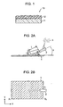
- Figs. 2A and 2b show a production of a mold used for duplicating a light-diffusing film.
- a surface of a mold base material 1 is processed by sandblasting to produce a mold for duplicating a translucent resin layer.
- the shape of this mold base material is not limited to a flat plate.
- the mold base material may have a roll shape or a conveyor shape, which is suitable for the continuous formation of a film.
- abrasives 3 are ejected from a blast gun 2 of a sandblasting machine (not shown) with compressed air so as to be sprayed on the surface of the mold base material 1.
- the abrasives 3 collide with the surface of the mold base material 1, thus forming irregularities on the surface of the mold base material 1.
- a polygonal ceramic having a particle diameter of 5 to 50 ⁇ m is used for the abrasives 3, but the abrasives 3 are not limited to this.
- Spherical particles or angulate particles e.g., polygonal particles having an average diameter of 1 to 1,000 ⁇ m and being composed of a resin, glass, a metal, a ceramic, or the like are preferable. Examples of the particles include glass beads, zirconia particles, steel grids, alumina particles, and silica particles.
- the mold base material 1 is a sheet composed of a material suited for the sandblasting process. This material is preferably a resin or a metal such as aluminum, copper, or steel. Aluminum is particularly preferable.
- the mold base material 1 should have a size so that a single mold base material 1 corresponds to the size of a light-diffusing film used in a screen. In a continuous production, the mold base material 1 should have a size that can correspond to the width of the light-diffusing film.
- All angles of spraying (angles of depression) of the abrasives 3 are less than 90 degrees to the principal surface of the mold base material 1.
- the abrasives 3 are sprayed with an angle of 10 degrees. Consequently, pitches of grooves in the spraying direction and the direction orthogonal to the spraying direction can be changed. The reason for this is as follows: Since each of the abrasives 3 collides with the mold base material 1 at an angle, the deformation shapes formed by the collision are different between the horizontal direction (the X-axis direction) and the vertical direction (the Y-axis direction). The parameters of the surface roughness such as the pitch can be adjusted by changing the conditions for sandblasting.
- abrasives having a large particle diameter can achieve a roughness with a large pitch in both the X-axis direction and the Y-axis direction.
- the use of abrasives having a larger density can achieve a shape with a deep groove.
- the use of a mold for duplicating a translucent resin layer produced under the above spraying conditions can provide a translucent resin layer 12 having different diffusion angles between the horizontal direction and the vertical direction or having anisotropy in the diffusing property between the horizontal direction and the vertical direction.
- the diffusion angle of reflected light or transmitted light is small in the X direction and is large in the Y direction.
- the blast gun 2 when the blast gun 2 is positioned closer to the mold base material 1, in other words, when an angle ⁇ in Fig. 2A becomes smaller, the horizontal to vertical ratio of the diffusion angle of the light-diffusing film, which will be described below, can be increased and the effect of anisotropy in the diffusing property can also be improved.
- the abrasives 3 are ejected from the blast gun 2 to the mold base material 1 at the angle ⁇ , which is the center, with an angle tolerance ⁇ .
- the abrasives 3 are incident on the mold base material 1 at an angle range of ⁇ 1 to ⁇ 2 and collide with the mold base material 1.
- the angle tolerance ⁇ is generally about 10 degrees.
- the angle tolerance ⁇ should be decreased or a distance L between the blast gun 2 and the mold base material 1 should be decreased.
- the sandblasting should be performed while the blast gun 2 or the mold base material 1 is moved smoothly.
- the blast gun 2 is preferably scanned above the mold base material 1 in the horizontal and vertical directions.
- the sandblasting may be performed on the entire principal surface of the mold base material 1.
- Fig. 3 shows an example of scanning of the blast gun 2.
- the blast gun 2 is moved in one direction of the Y axis above the mold base material 1 at a constant speed while the abrasives 3 are ejected from the blast gun 2.
- the blast gun 2 is moved in the X-axis direction with a certain pitch.
- the blast gun 2 is then moved in the opposite direction of the Y-axis at the constant speed.
- the blast gun 2 is moved in the X-axis direction with the certain pitch and the movement in the Y-axis direction is then reversed to perform the sandblasting continuously.
- desired irregularities are formed on the entire surface of the mold base material 1.
- the moving pitch in the X-axis direction is preferably adjusted so that the adjacent collision areas of the abrasives 3 overlap to a certain degree and the surface of the mold base material 1 has a uniform irregular shape as a whole.
- a mask may be disposed at a collision area of the abrasives 3 so that the abrasives 3 collide on only the central area of the collision area of the mold base material 1.
- the mold base material 1 may be fixed and the blast gun 2 may be moved.
- a stage provided with the mold base material 1 may be moved in the X-axis direction and the blast gun 2 may be moved in the Y-axis direction.
- a finely carved surface having an irregular shape is formed on the surface of the mold base material 1.
- This irregular shape becomes an original mold of a surface shape of the translucent resin layer 12, which is a final product.
- the translucent resin layer 12 is formed using this finely carved surface.
- the present invention can be applied to any method for producing a translucent resin layer 12 from the above finely carved surface.
- an electroformed mold on which a finely carved surface is transferred may be produced using a substrate having the finely carved surface and the translucent resin layer 12 may then be directly or indirectly formed with the electroformed mold.
- Fig. 4 is a cross-sectional view showing a structure of a screen according to a first embodiment of the present invention.
- a screen 100 is a reflective screen including a reflective sheet 50 and a light-diffusing film 10.
- the light-diffusing film 10 may be formed directly on the reflective sheet 50 or may be bonded with the reflective sheet 50.
- the reflective sheet 50 has a reflection property to a plurality of light components each having a specific wavelength range, the light components corresponding to projector light, i:e., image light, and an absorption property to light components each having a visible wavelength range except for the plurality of specific wavelength ranges.
- the specific wavelength ranges preferably include wavelength ranges of light components of each of RGB three primary colors, which are used as the image light in a light source of a projector.
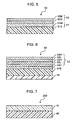
- Fig. 5 shows an example of the structure of a reflective sheet 50 including an optical multilayer film 52 and a reflective layer 51.
- the optical multilayer film 52 includes a dielectric film 52D and a light-absorbing thin-film 52M having a transmissivity.
- the reflective layer 51 includes a substrate 51B and a metal film 51M provided on the substrate 51B. This reflective layer 51 reflects light transmitted through the optical multilayer film 52.
- the substrate 51B forms a support of the reflective sheet 50.
- the substrate 51B is composed of a flexible polymer such as polycarbonate (PC), polyethylene terephthalate (PET), polyethylene naphthalate (PEN), polyethersulfone (PES), or a polyolefin (PO).
- PC polycarbonate
- PET polyethylene terephthalate
- PEN polyethylene naphthalate
- PES polyethersulfone
- PO polyolefin
- the metal film 51M is composed of a metal that reflects visible light with high reflectivity.
- the metal film 51M is composed of A1, Au, or Ag, and preferably has a thickness of 50 nm or more.
- the metal film 51M may be formed on the substrate 51B by any method such as vapor deposition, plating, or applying.
- the reflective layer 51 may be a metal substrate composed of the same material as that of the metal film 51M instead of the reflective layer 51 shown in Fig. 5 , which includes the substrate 51B and the metal film 51M provided thereon.
- the optical multilayer film 52 includes the dielectric film 52D and the light-absorbing thin-film 52M having a transmissivity.
- the optical multilayer film 52 is composed of at least two layers and has a selective reflection property.
- a plurality of dielectric films 52D and a plurality of light-absorbing thin-films 52M having a transmissivity may be alternately laminated.
- a plurality of kinds of dielectric film 52D may be sequentially laminated.
- the dielectric film 52D is composed of a material that is transparent at least in the visible wavelength region.
- the dielectric film 52D is composed of Nb 2 O 5 , TiO 2 , Ta 2 O 5 , Al 2 O 3 , or SiO 2 .
- the larger the refractive index of the dielectric film 52D the larger the half width of the reflection peak in the wavelength range of each light component of the three primary colors.
- the smaller the refractive index of the dielectric film 52D the smaller the half width. In view of this tendency, the dielectric material should be appropriately selected according to the desired selective reflection property.
- the light-absorbing thin-film 52M having a transmissivity is composed of a material having a refractive index of 1 or more and an absorption coefficient of 0.5 or more.
- the light-absorbing thin-film 52M preferably has a thickness of 5 to 20 nm. Examples of such a material include Nb, Nb alloys, C, Cr, Fe, Ge, Ni, Pd, Pt, Rh, Ti, TiN, TiN x W y , Mn, Ru, and PbTe.
- Each film of the optical multilayer film 52 can be formed by a dry process such as sputtering.
- Each film thickness of the optical multilayer film 52 is designed as follows:
- the optical multilayer film 52 has a high reflection property with a reflectivity of at least 50% to the light components having wavelength ranges of the three primary colors, the light components having wavelength ranges of each color of red, green, and blue.
- the optical multilayer film 52 has a high absorption property with an absorptivity of at least 80% to light components having wavelength ranges except for the wavelength ranges of the light components of the three primary colors.
- a reflective sheet 50 includes a metal film 51M composed of Al (thickness: 50 nm) and an optical multilayer film 52 having a three-layer structure composed of Nb 2 O 5 /Nb/Nb 2 O 5 (thickness of each film: 560 nm/19 nm/550 nm (adjacent to the A1 film)).
- the reflective sheet 50 has a high reflectivity of at least 50% to the light components having wavelength ranges of the three primary colors and has a high absorptivity of at least 80% to light components (stray light) each having a wavelength range except for the wavelength ranges of the light components of the three primary colors for projector light (the light from a light source of a projector using a laser oscillator).
- Fig. 6 shows another example of the structure of a reflective sheet 50.
- the reflective sheet 50 includes a substrate 51B, an optical multilayer film 53 provided on the substrate 51B, and a light-absorbing layer 54 provided on the reverse face of the substrate 51B.
- the optical multilayer film 53 has a reflection property to light components having wavelength ranges of each of the RGB three primary colors and a transmissive property to light components having wavelength ranges except for the above wavelength ranges of each of the RGB three primary colors among the wavelength range of the projector light.
- the substrate 51B may be the same substrate as that in Fig. 5 .
- the optical multilayer film 53 has a selective reflection property.
- high refractive index films 53H and low refractive index films 53L are alternately laminated.
- the low refractive index films 53L have a refractive index lower than that of the high refractive index films 53H.
- the high refractive index films 53H and the low refractive index films 53L can be formed by either a dry process such as sputtering or a wet process such as spin coating or dip coating.
- the high refractive index films 53H When the high refractive index films 53H are formed by a dry process, various materials having a refractive index of about 2.0 to about 2.6 can be used for the high refractive index films 53H.
- the low refractive index films 53L When the low refractive index films 53L are formed by a dry process, various materials having a refractive index of about 1.3 to about 1.5 can be used for the low refractive index films 53L.
- the high refractive index films 53H may be composed of TiO 2 , Nb 2 O 5 , or Ta 2 O 5
- the low refractive index films 53L may be composed of SiO 2 or MgF 2 .
- the thickness of each film of the optical multilayer film 53 is preferably designed by a simulation based on a matrix method so that the optical thin-film has a high reflection property to light components having specific wavelength ranges and has a high transmissive property to light components having at least a visible wavelength range except for the above wavelength ranges.
- the simulation based on a matrix method is a method disclosed in Japanese Unexamined Patent Application Publication No. 2003-270725 . In the method, a simulation is performed using an equation based on the following principle to design the film thickness of an optical film having desired characteristics.
- the principle is as follows: When light is incident at an angle ⁇ 0 on a multilayer optical thin-film system composed of a plurality of different materials in which a multiple reflection is generated at the boundary of each layer, the phase is aligned depending on the type and the wavelength of a light source used and the optical film thickness (i.e., the product of the refractive index and the geometrical film thickness) of each layer. As a result, the reflected beam of light may exhibit coherence and interfere with each other.
- wavelength ranges of light components of each of RGB three primary colors should be selected as the specific wavelength range.
- the film thickness should be designed by a simulation based on the matrix method so that only light components having these wavelength ranges are reflected and light components having wavelength ranges except for the above wavelength ranges are transmitted.
- High refractive index films 53H and low refractive index films 53L having thicknesses satisfying the above condition overlap with each other, thereby reliably achieving the optical multilayer film 53 that satisfactorily functions as a filter for wavelength ranges of the three primary colors.
- the number of layers of the optical film constituting the optical multilayer film 53 formed by a dry process is not particularly limited and may be a desired number of layers.
- the optical multilayer film 53 is preferably composed of an odd number of layers in which the outermost layers at the light-incident side and the opposite side are high refractive index films 53H.
- high refractive index films 53H are formed by applying a solvent-based coating material for a high refractive index film and curing the coating material
- low refractive index films 53L are formed by applying a solvent-based coating material for a low refractive index film and curing the coating material.
- the solvent-based coating material for a low refractive index film provides an optical film having a refractive index lower than that of the high refractive index films 53H.
- the optical multilayer film 53 is preferably composed of an odd number of layers in which the high refractive index films 53H and the low refractive index films 53L are alternately laminated.
- Each of the optical film is preferably formed by applying a coating material containing a resin that is subjected to a curing reaction by absorbing energy provided by heating, ultraviolet irradiation, or the like.
- the high refractive index films 53H are preferably composed of a thermosetting resin of Opster from JSR Corporation (JN7102, refractive index: 1.68)
- the low refractive index films 53L are preferably composed of a thermosetting resin of Opster from JSR Corporation (JN7215, refractive index: 1.41).
- Such an optical multilayer film 53 has flexibility.
- the material of the high refractive index films 53H is not limited to the above thermosetting resin.
- the material may be a solvent-based coating material that provides a refractive index of about 1.6 to about 2.1.
- a material for an optical film having a high refractive index described in the above light-diffusing film may be used.
- the material of the low refractive index films 53L is not limited to the above thermosetting resin.
- the material may be a solvent-based coating material that provides a refractive index of about 1.3 to about 1.59.
- a material for an optical film having a low refractive index described in the above light-diffusing film may be used.
- each film thickness of the optical multilayer film 53 is designed as follows:
- the optical multilayer film 53 has a high reflection property with a reflectivity of at least 50% to light components having wavelength ranges of the three primary colors, the light components having wavelength ranges of each color of red, green, and blue.
- the optical multilayer film 53 has a high transmissive property with a transmittance of at least 80% to light components having wavelength ranges except for the wavelength ranges of light components of the three primary colors.
- the thickness of each film of the optical multilayer film 53 is preferably designed so as to satisfy the above equation (1).
- each high refractive index film 53H (refractive index: 1.68) has a thickness of 1,023 nm and each low refractive index film 53L (refractive index: 1.41) has a thickness of 780 nm.
- Nine high refractive index films 53H and nine low refractive index films 53L are alternately laminated and a high refractive index film 53H is further laminated on the laminate to form an optical multilayer film 53 having a 19-layer structure.
- a multilayer film has a high reflectivity of at least 80% to the light components having wavelength ranges of the three primary colors and has a high transmissive property with a reflectivity of 20% or less to light components (stray light) each having a wavelength range except for the wavelength ranges of the light components of the three primary colors for projector light (the light from a light source of a projector using a laser oscillator).
- the light-absorbing layer 54 is a black coated film formed by applying a black coating material on the reverse face of the substrate 51B, or a black film applied on the reverse face of the substrate 51B.
- the light-absorbing layer 54 has a function of light absorption. According to this structure, the light-absorbing layer 54 absorbs light transmitted through the optical multilayer film 53 to prevent the reflection of transmitted light. As a result, in the reflective sheet 50, only the light components having wavelength ranges of the three primary colors can be more reliably obtained as reflected light.
- the substrate 51B may contain a black coating material or the like so that the color of the substrate 51B is black. Thus, the substrate 51B itself may function as a light-absorbing layer.
- light components having specific wavelength ranges can be reflected with high reflectivity and light components (external light) having wavelength ranges except for the specific wavelength ranges can be absorbed, corresponding to light projected from a light source of a projector.
- the screen 100 Since the screen 100 includes a reflective sheet 50, the screen 100 reflects light components having wavelength ranges of the three primary colors. Therefore, a viewer views a reflected image of an image projected on this screen. In other words, the viewer views only reflected light of the image projected on the reflective screen.
- the reflected light on the screen is composed of only specular components, for example, it is difficult to view satisfactory images and the field of view is limited. This is disadvantageous to a viewer and the natural images are difficult to be viewed.
- the screen 100 further includes a light-diffusing film 10, thereby scattered reflected light from the screen 100 can be viewed.
- the structure including the light-diffusing film 10 provided on the reflective sheet 50 in the incident light passed through the light-diffusing film 10, light components having specific wavelength ranges are selectively reflected on the reflective sheet 50.
- the reflected light is diffused when passed through the light-diffusing film 10, thereby obtaining scattered reflected light other than the specular components. Consequently, the light reflected from the reflective screen 100 includes the specular components and the scattered reflected light.
- the viewer can observe the scattered reflected light in addition to the specular components, thus significantly improving the characteristics of the field of view. As a result, the viewer can view natural images.
- the light-diffusing film 10 is used as the light-diffusing film in the screen 100. Therefore, the damage of the surface of the light-diffusing film can be prevented when the light-diffusing film is released from a mold and during storing and handling of the light-diffusing film. Accordingly, normal reflected images can be viewed. Furthermore, when image light is projected and the screen is viewed from the vicinity of the front, an image having a uniform and high luminance can be viewed at a specific position. Thus, it can be confirmed that the reflected image light is controlled so as to be directed in a specific field of view.
- the reflective sheet 50 in the above embodiment includes a wavelength-selective reflective layer.
- the reflective layer is not limited to this so long as the reflective layer can reflect the projected image light.
- the reflective layer may be composed of a material having a high reflectivity over a wide wavelength range of visible light, for example, aluminum or silver.
- Fig. 7 is a cross-sectional view showing a structure of a screen according to a second embodiment of the present invention.
- a screen 200 is a transmissive screen including a support 60 and a light-diffusing film 10 provided on the support 60.
- the support 60 functions as a support of the screen 200 and is composed of a polymer such as polyethylene terephthalate (PET), polyethylene naphthalate (PEN), polyethersulfone (PES), or a polyolefin (PO).
- PET polyethylene terephthalate
- PEN polyethylene naphthalate
- PES polyethersulfone
- PO polyolefin
- incident light is received on a surface of the support 60, the surface opposite to the surface having the light-diffusing film 10 thereon.
- the incident light is transmitted through the support 60, scattered on the light-diffusing film 10, and is emitted.
- the viewer can view natural images by viewing this scattered reflected light.
- the light-diffusing film 10 is used as the light-diffusing film in the screen 200. Therefore, the damage of the surface of the light-diffusing film can be prevented when the light-diffusing film is released from a mold and during storing and handling of the light-diffusing film. Accordingly, normal transmitted images can be viewed.
- the screen 200 according to the second embodiment of the present invention is prepared by, for example, applying the light-diffusing film 10 on a surface of the support 60 composed of a PET film.
- a translucent resin layer 12 may be formed on the support 60.
- the surface shape of the light-diffusing film 10 is preferably controlled with respect to each screen position, thereby adjusting the diffusing property.
- the luminance distribution of the entire screen viewed from a viewer is controlled to be uniform.
- the shift of axis of a luminance peak is preferably in the direction of the central part of the screen.
- the peak of the luminance of the transmitted light is tilted in the direction of the central part of the screen, and the tilt is continuously changed to be increased as the position is shifted from the central part to the peripheral part of the screen.
- the scope of application of the light-diffusing film according to an embodiment of the present invention is not limited to projection display devices described above.
- the light-diffusing film.according to an embodiment of the present invention can be applied to various fields such as display devices in which the viewing angle is controlled, for example, a backlight for a liquid crystal display, or lighting systems.
- a light-diffusing sheet was prepared under the following conditions.
- a mold for duplicating a translucent resin layer was prepared by sandblasting under the following conditions.
- the resultant surface of the mold had different irregular shapes between the vertical direction and the horizontal direction.
- a value of Sm (average distance of irregularities) was measured as a parameter of the surface shape with an ET4000A stylus type micro figure measuring instrument (from Kosaka Laboratory Ltd.).
- Light-diffusing films were prepared as in Example 1 except that UV curable acrylic resins (resin materials B, C, D, and E) each having a different glass transition temperature were used as the resin material.
- a light-diffusing film was prepared as in Example 2 except that, in the preparation of a mold for duplicating a translucent resin layer, the angle formed by the blast gun and the mold base material was changed during sandblasting.
- Light-diffusing films were prepared as in Example 1 except that UV curable acrylic resins (resin materials F, G, and H) each having a different glass transition temperature were used as the resin material.
- a translucent resin layer was formed under the following conditions. The same translucent support as that in Example 1 was used.
- the light-diffusing films prepared as described above were evaluated as follows.
- a sample of 5 mm x 50 mm was cut out from a light-diffusing film.
- the viscoelasticity of the light-diffusing film sample was measured with a DVA220 dynamic viscoelastometer from IT Keisoku Seigyo Co., Ltd.
- the viscoelasticity was measured in a tensile mode under a constant strain with a frequency of 5 Hz while the temperature was increased from -50°C to 200°C at a heating rate of 2°C/min.
- a tensile dynamic viscoelasticity was determined.
- the viscoelasticity of only the PET film i.e., the translucent support
- the measured maximal temperature of the loss tangent (tan ⁇ ) was 115°C. This result showed that the maximal temperature of the loss tangent (tan ⁇ ) observed at 115°C in a light-diffusing film was resulted from the translucent support.
- step S24 the appearance of a light-diffusing film when released from a mold was visually evaluated.
- the pencil hardness of the translucent resin layer side of a light-diffusing film was measured at room temperature in accordance with a method described in Japanese Industrial Standard (JIS) 5600-5-4.
- a glass flat plate was disposed on the surface of the translucent resin layer side of a light-diffusing film at 60°C.
- a load of 1,000 g/cm 2 was applied on the glass plate and this state was kept for 72 hours. Subsequently, the temperature was decreased to room temperature and the surface of the light-diffusing film was visually observed.
- the sample was evaluated as NG (unsatisfactory).
- the trace of weighting was not visually seen, the sample was evaluated as OK (satisfactory).
- a test corresponding to a situation in which a translucent resin layer was bent at an acute angle during handling of a light-diffusing film was performed as follows.
- the PET film surface (i.e., the surface opposite to another surface having a translucent resin layer thereon) of a light-diffusing film was in contact with an iron rod having a diameter of 1 mm at room temperature.
- the light-diffusing film was bent 20 times so that an angle formed by the light-diffusing film around the rod was 30 degrees. Subsequently, the surface state of the light-diffusing film was visually observed.
- the trace of the bending was visible, the sample was evaluated as NG (unsatisfactory).
- the trace of bending was not visible, the sample was evaluated as OK (satisfactory) .
- Table 1 shows the evaluation results.
- light-diffusing films according to embodiments of the present invention showed satisfactory results in the releasing property from a mold in the formation of a film, the pencil hardness, the load test, and the bending test, while the anisotropy of diffusion angle was maintained (described below). Since the maximal temperature of the loss tangent (tan ⁇ ) determined from the dynamic viscoelasticity lies in the range of the present invention (from 0°C to 60°C), the translucent resin layer is in a state having an adequate strength and flexibility. Consequently, the translucent resin layer can simultaneously satisfy the pencil hardness test and the load test on which the strength of the translucent resin layer affects, and the bending test and the releasing property from a mold on which the flexibility affects.
- the translucent resin layer When the maximal temperature of the loss tangent (tan ⁇ ) was lower than a temperature in the range of the present invention, the translucent resin layer was excessively flexible. As a result, the translucent resin layer was easily adhered to the mold. In addition, such an excessively low maximal temperature of the loss tangent (tan ⁇ ) caused a deformation in the load test and a decrease in the pencil hardness. On the other hand, when the maximal temperature of the loss tangent (tan ⁇ ) was higher than a temperature in the range of the present invention, the translucent resin layer was hard and brittle. As a result, the film was cracked during releasing from the mold and during the bending test. The pencil hardness was also decreased because of the brittleness.
- a reflective layer was formed on the PET film surface (i.e., the surface opposite to another surface having a translucent resin layer thereon) of each light-diffusing film in Examples 1 to 6 and Comparative Examples 1 to 4 by aluminum evaporation.
- reflective screens each having a size of 100 inches with a ratio of 4:3 were prepared.
- a diffusion angle was determined from a state of the luminance distribution of reflected light on each screen.
- a liquid crystal projector VPL-CX5 from SONY Corporation
- VPL-CX5 liquid crystal projector
- the distance between the screen and the projector was 2 m.
- the position of a projection lens of the projector was set to zero degrees.
- a luminance meter (BM-9 from TOPCON Corporation) was scanned on a circular arc with a radius of 2 m, the circular arc having its center on a light-diffusion film of the screen.
- An angle at which the luminance was half (half width) of the maximum luminance was defined as the diffusion angle. Diffusion angles in the vertical direction and in the horizontal direction of the screen were determined.
- a liquid crystal projector (VPL-CX5 from SONY Corporation) with an optical output of 2000 ANSI lumen was disposed so as to face a screen, and a white image was projected.
- the projector was positioned away from a surface having a screen by 2 m in the horizontal direction.
- a luminance S at the central part of the screen was measured with a luminance meter (BM-9 from TOPCON Corporation).
- a luminance W when a standard white board was disposed at the same position was also measured.
- the ratio of the luminance S to the luminance W (S/W) was calculated and was defined as a screen gain.
- the in-plane luminance distribution on the screen was visually evaluated.
- Table 2 shows the evaluation results.
- Example F a screen in which the screen gain was high and the directivity of the reflected light in the horizontal direction was strong could be produced.
Landscapes
- Physics & Mathematics (AREA)
- General Physics & Mathematics (AREA)
- Engineering & Computer Science (AREA)
- Mechanical Engineering (AREA)
- Optics & Photonics (AREA)
- Health & Medical Sciences (AREA)
- Manufacturing & Machinery (AREA)
- Ophthalmology & Optometry (AREA)
- Optical Elements Other Than Lenses (AREA)
- Overhead Projectors And Projection Screens (AREA)
- Laminated Bodies (AREA)
Claims (9)
- Ein lichtstreuender Film (10) mit einer Anisotropie im Streuwinkel, wobei der lichtstreuende Film umfasst:einen lichtdurchlässigen Träger (11) undeine lichtdurchlässige Harzschicht (12), die Unregelmäßigkeiten auf ihrer Oberfläche aufweist und auf dem lichtdurchlässigen Träger (11) vorgesehen ist,wobeider Streuwinkel in der horizontalen und der vertikalen Richtung unterschiedlich ist,der Streuwinkel in der horizontalen Richtung größer als der Streuwinkel in der vertikalen Richtung ist, unddadurch gekennzeichnet,dass die Unregelmäßigkeiten auf der lichtdurchlässigen Harzschicht (12) durch Übertragung einer unregelmäßigen Form von der Oberfläche einer Gussform gebildet wurden, wobei die unregelmäßige Form auf der Oberfläche der Gussform durch Sandstrahlen dergestalt gebildet wurde, dass alle Winkel des Versprühens von abrasiven Materialien kleiner als 90° sind, so dass der mittlere Abstand der Unregelmäßigkeiten in der horizontalen Richtung und der vertikalen Richtung unterschiedlich ist,dass der aus einer dynamischen Viskoelastizität des lichtstreuenden Filmes bestimmte Maximalwert der Verlusttangente (tan δ) in einem Temperaturbereich von 0 °C bis 60 °C liegt.
- Ein lichtstreuender Film (10) gemäß Anspruch 1, wobei die Bleistifthärte mehr als 3 H beträgt.
- Ein Bildschirm (100) mit:einem lichtstreuendem Film (10) gemäß Anspruch 1 oder 2, undeiner reflektierenden Schicht (50), die auf einer Oberfläche des lichtstreuenden Films (10) vorgesehen ist, die der lichtdurchlässigen Harzschicht (12) gegenüberliegt.
- Ein Bildschirm (100) gemäß Anspruch 3, wobei
die reflektierende Schicht (50) eine Reflektionseigenschaft für eine Mehrzahl von ersten Wellenlängenbereichen im sichtbaren Spektrum aufweist. - Ein Bildschirm (100) gemäß Anspruch 3 oder 4, wobei die ersten Wellenlängenbereiche Wellenlängen entsprechend einer roten Farbe, einer blauen Farbe oder einer grünen Farbe aufweisen.
- Ein Bildschirm (100) gemäß einem der Ansprüche 3 bis 5,
wobei die reflektierende Schicht (50) eine Absorptionseigenschaft für eine Vielzahl von zweiten Wellenlängenbereichen in dem sichtbaren Spektrum und außerhalb der Vielzahl von ersten Wellenlängenbereichen aufweist. - Ein Bildschirm (100) gemäß Anspruch 6,
wobei die Absorptionseigenschaft durch ein Absorptionsvermögen von zumindest 80 % beschrieben ist. - Eine Projektoreinheit, mit:einem Projektor zum Projizieren von Licht, das aus drei Lichtkomponenten entsprechend den drei Primärfarben zusammengesetzt ist, wobei jede Lichtkomponente Licht eines für diese Komponente spezifischen Wellenlängenbereiches aufweist,einem Bildschirm (100) gemäß einem der Ansprüche 3 bis 7, wobei die ersten Wellenlängenbereiche durch die drei für die drei Lichtkomponenten spezifischen Wellenlängenbereiche gegeben sind.
- Eine Projektoreinheit gemäß Anspruch 8,
wobei der Projektor eine Lichtquelle umfasst, die ausgelegt ist, auf einem Laseroszillator basierendes Licht zu erzeugen.
Applications Claiming Priority (1)
| Application Number | Priority Date | Filing Date | Title |
|---|---|---|---|
| JP2004254328A JP4244889B2 (ja) | 2004-09-01 | 2004-09-01 | 反射型スクリーン用光拡散フィルム及びその製造方法、反射型スクリーン用スクリーン |
Publications (2)
| Publication Number | Publication Date |
|---|---|
| EP1632796A1 EP1632796A1 (de) | 2006-03-08 |
| EP1632796B1 true EP1632796B1 (de) | 2012-02-22 |
Family
ID=35447666
Family Applications (1)
| Application Number | Title | Priority Date | Filing Date |
|---|---|---|---|
| EP05018905A Expired - Lifetime EP1632796B1 (de) | 2004-09-01 | 2005-08-31 | Lichtstreuender Film und Bildschirm mit einem solchen Film |
Country Status (6)
| Country | Link |
|---|---|
| US (1) | US7990618B2 (de) |
| EP (1) | EP1632796B1 (de) |
| JP (1) | JP4244889B2 (de) |
| KR (1) | KR101088123B1 (de) |
| CN (1) | CN1746703B (de) |
| TW (1) | TW200622472A (de) |
Families Citing this family (16)
| Publication number | Priority date | Publication date | Assignee | Title |
|---|---|---|---|---|
| JP2006335028A (ja) * | 2005-06-06 | 2006-12-14 | Sony Corp | 光拡散シート複製用金型の製造方法、光拡散シート及びその製造方法、並びにスクリーン |
| KR20070073543A (ko) * | 2006-01-05 | 2007-07-10 | 최해용 | 고선명 박막 반사 스크린 |
| JP4844254B2 (ja) * | 2006-06-20 | 2011-12-28 | 住友化学株式会社 | 防眩フィルム及び画像表示装置 |
| TWI295355B (en) * | 2006-08-30 | 2008-04-01 | Ind Tech Res Inst | Optical diffusion module and method of manufacturing optical diffusion structure |
| TWI364622B (en) * | 2007-11-06 | 2012-05-21 | Ind Tech Res Inst | Image screen |
| JP5379162B2 (ja) * | 2008-01-10 | 2013-12-25 | コーロン インダストリーズ インク | 光学シート |
| CN102123859B (zh) * | 2008-08-12 | 2016-09-14 | 3M创新有限公司 | 与腐蚀敏感层相容的粘合剂 |
| WO2010080775A1 (en) * | 2009-01-08 | 2010-07-15 | 3M Innovative Properties Company | Front projection screen with high contrast |
| JP5630076B2 (ja) * | 2010-06-03 | 2014-11-26 | 大日本印刷株式会社 | 反射スクリーン、映像表示システム、反射スクリーンの製造方法 |
| JP4888585B2 (ja) * | 2010-06-16 | 2012-02-29 | ソニー株式会社 | 光学体、壁材、建具、および日射遮蔽装置 |
| JP2012018424A (ja) * | 2011-10-18 | 2012-01-26 | Sony Corp | 光学体、壁材、建具、および日射遮蔽装置 |
| TWI495552B (zh) * | 2012-12-20 | 2015-08-11 | Jiin Ming Industry Co Ltd | Method of manufacturing transfer die |
| JP2015099397A (ja) * | 2015-02-19 | 2015-05-28 | デクセリアルズ株式会社 | 光学体、壁材、建具、および日射遮蔽装置 |
| CN106291789A (zh) * | 2016-08-02 | 2017-01-04 | 青岛海信电器股份有限公司 | 一种反射片及其制备方法、背光模组、显示装置 |
| EP3569182A4 (de) * | 2017-01-11 | 2020-01-22 | Sony Corporation | Informationsverarbeitungsvorrichtung, informationsverarbeitungsverfahren, programm, bildschirm und informationszeichensystem |
| CN108169994A (zh) * | 2018-03-05 | 2018-06-15 | 深圳市鸿益源科技有限公司 | 一种投影玻璃屏幕 |
Family Cites Families (25)
| Publication number | Priority date | Publication date | Assignee | Title |
|---|---|---|---|---|
| JPS5351755A (en) | 1976-10-21 | 1978-05-11 | Canon Inc | Preparing apparatus for speckle diffusion plate |
| US4427265A (en) * | 1980-06-27 | 1984-01-24 | Canon Kabushiki Kaisha | Diffusion plate |
| JP2822032B2 (ja) | 1987-01-28 | 1998-11-05 | 大日本印刷株式会社 | 透過型スクリーン用レンズ板 |
| JPH01298302A (ja) | 1988-05-26 | 1989-12-01 | Dainippon Printing Co Ltd | レンズシート用ベース部材とそれを用いたレンズシートの製造方法 |
| US5189454A (en) * | 1989-02-28 | 1993-02-23 | Canon Kabushiki Kaisha | Phase-type focusing screen and process for manufacturing the same |
| JP3011802B2 (ja) | 1991-10-08 | 2000-02-21 | 大日本印刷株式会社 | フレネルレンズシート |
| EP0714348A4 (de) | 1993-07-27 | 1998-05-06 | Physical Optics Corp | Vorrichtung zum destrukturieren und aufbauen einer lichtquelle |
| US5850300A (en) * | 1994-02-28 | 1998-12-15 | Digital Optics Corporation | Diffractive beam homogenizer having free-form fringes |
| JP2002534705A (ja) * | 1998-12-31 | 2002-10-15 | マイクロシャープ コーポレイション リミテッド | 段が形成されている面をもつディフューザー |
| JP3430098B2 (ja) | 1999-01-21 | 2003-07-28 | 恵和株式会社 | 光拡散シート及びこれを用いたバックライトユニット |
| JP2000280267A (ja) | 1999-03-30 | 2000-10-10 | Fuji Photo Film Co Ltd | 光拡散体の製造方法 |
| JP2000284106A (ja) | 1999-03-31 | 2000-10-13 | Hitachi Chem Co Ltd | 光拡散部材、光拡散部材の製造法及び転写フィルム |
| CN1372502A (zh) * | 1999-09-01 | 2002-10-02 | 西门子公司 | 部件的表面处理方法及装置 |
| KR100769779B1 (ko) * | 2000-01-13 | 2007-10-24 | 닛토덴코 가부시키가이샤 | 광학 필름 및 액정 디스플레이 장치 |
| EP1364233B1 (de) * | 2000-08-01 | 2013-01-02 | Aztec Systems, Inc. | Gerichteter diffusor |
| CN1735970A (zh) | 2000-11-02 | 2006-02-15 | 3M创新有限公司 | 直观式发射显示器亮度和对比度的提高 |
| DE10105957A1 (de) * | 2001-02-09 | 2002-09-19 | Fraunhofer Ges Forschung | Verfahren zur Herstellung von Licht streuenden Elementen |
| JP2003084101A (ja) * | 2001-09-17 | 2003-03-19 | Dainippon Printing Co Ltd | 光学素子用樹脂組成物、光学素子、およびプロジェクションスクリーン |
| JP2003177221A (ja) | 2001-10-02 | 2003-06-27 | Olympus Optical Co Ltd | 拡散板及びそれを用いた投影表示装置 |
| JP2003147209A (ja) | 2001-11-09 | 2003-05-21 | Dainippon Printing Co Ltd | 光学素子用樹脂組成物、光学素子、およびプロジェクションスクリーン |
| JP2003313445A (ja) | 2002-02-20 | 2003-11-06 | Dainippon Printing Co Ltd | 光学素子用樹脂組成物、光学素子、およびプロジェクションスクリーン |
| US7371805B2 (en) * | 2002-06-27 | 2008-05-13 | Asahi Kasei Chemicals Corporation | Hydrogenated copolymer and composition thereof |
| JP3982377B2 (ja) | 2002-10-08 | 2007-09-26 | Jsr株式会社 | 光硬化性樹脂組成物及び光学部材 |
| JP2005031502A (ja) * | 2003-07-09 | 2005-02-03 | Sony Corp | スクリーン |
| JP4843952B2 (ja) | 2004-02-04 | 2011-12-21 | ソニー株式会社 | 光拡散シート複製用金型の製造方法、光拡散シート及びその製造方法、並びにスクリーン |
-
2004
- 2004-09-01 JP JP2004254328A patent/JP4244889B2/ja not_active Expired - Fee Related
-
2005
- 2005-08-25 US US11/211,897 patent/US7990618B2/en not_active Expired - Fee Related
- 2005-08-30 TW TW094129672A patent/TW200622472A/zh not_active IP Right Cessation
- 2005-08-31 KR KR1020050080538A patent/KR101088123B1/ko not_active Expired - Fee Related
- 2005-08-31 EP EP05018905A patent/EP1632796B1/de not_active Expired - Lifetime
- 2005-09-01 CN CN2005101132174A patent/CN1746703B/zh not_active Expired - Fee Related
Also Published As
| Publication number | Publication date |
|---|---|
| EP1632796A1 (de) | 2006-03-08 |
| JP2006071898A (ja) | 2006-03-16 |
| JP4244889B2 (ja) | 2009-03-25 |
| CN1746703B (zh) | 2010-12-08 |
| KR101088123B1 (ko) | 2011-12-02 |
| CN1746703A (zh) | 2006-03-15 |
| TWI310875B (de) | 2009-06-11 |
| TW200622472A (en) | 2006-07-01 |
| US20060050188A1 (en) | 2006-03-09 |
| KR20060050855A (ko) | 2006-05-19 |
| US7990618B2 (en) | 2011-08-02 |
Similar Documents
| Publication | Publication Date | Title |
|---|---|---|
| KR101231116B1 (ko) | 광확산 시트 및 그 제조 방법과 스크린 | |
| EP1632796B1 (de) | Lichtstreuender Film und Bildschirm mit einem solchen Film | |
| KR101117366B1 (ko) | 대전 방지 방현 필름 | |
| CN101836136B (zh) | 防眩膜、防眩性偏振板及图像显示装置 | |
| US7710644B2 (en) | Method for producing mold for use in duplicating light diffusion sheet, light diffusion sheet and method for producing the same, and screen | |
| JP2007011303A (ja) | 遮光層付フライアイレンズシートおよびその製造方法、透過型スクリーンならびに背面投影型画像表示装置 | |
| KR20080012340A (ko) | 광확산판과 그 제조 방법 | |
| JP5521357B2 (ja) | プリズムシート、それを用いたバックライトユニットおよび液晶表示装置 | |
| JP2017173440A (ja) | 反射スクリーン、映像表示システム | |
| JP2005266264A (ja) | スクリーン | |
| JP2006337906A (ja) | 光拡散フィルム及びスクリーン | |
| JP7521364B2 (ja) | 映像表示装置 | |
| KR100859365B1 (ko) | 투과형 스크린용 광확산 부재 | |
| JP2016180855A (ja) | 反射スクリーン、映像表示システム | |
| JP2006335028A (ja) | 光拡散シート複製用金型の製造方法、光拡散シート及びその製造方法、並びにスクリーン | |
| JP2024043660A (ja) | 映像表示装置、反射型スクリーン | |
| JP2006301311A (ja) | 光機能性拡散板、反射型スクリーン及びその製造方法 | |
| JP2000314924A (ja) | 透過型スクリーン | |
| JP2012150354A (ja) | 光学シート、表示装置、及び光学シートの製造方法 |
Legal Events
| Date | Code | Title | Description |
|---|---|---|---|
| PUAI | Public reference made under article 153(3) epc to a published international application that has entered the european phase |
Free format text: ORIGINAL CODE: 0009012 |
|
| AK | Designated contracting states |
Kind code of ref document: A1 Designated state(s): AT BE BG CH CY CZ DE DK EE ES FI FR GB GR HU IE IS IT LI LT LU LV MC NL PL PT RO SE SI SK TR |
|
| AX | Request for extension of the european patent |
Extension state: AL BA HR MK YU |
|
| 17P | Request for examination filed |
Effective date: 20060720 |
|
| 17Q | First examination report despatched |
Effective date: 20060823 |
|
| AKX | Designation fees paid |
Designated state(s): DE FR GB |
|
| GRAP | Despatch of communication of intention to grant a patent |
Free format text: ORIGINAL CODE: EPIDOSNIGR1 |
|
| GRAS | Grant fee paid |
Free format text: ORIGINAL CODE: EPIDOSNIGR3 |
|
| GRAA | (expected) grant |
Free format text: ORIGINAL CODE: 0009210 |
|
| AK | Designated contracting states |
Kind code of ref document: B1 Designated state(s): DE FR GB |
|
| REG | Reference to a national code |
Ref country code: GB Ref legal event code: FG4D |
|
| REG | Reference to a national code |
Ref country code: DE Ref legal event code: R096 Ref document number: 602005032751 Country of ref document: DE Effective date: 20120419 |
|
| PGFP | Annual fee paid to national office [announced via postgrant information from national office to epo] |
Ref country code: GB Payment date: 20120821 Year of fee payment: 8 |
|
| PLBE | No opposition filed within time limit |
Free format text: ORIGINAL CODE: 0009261 |
|
| STAA | Information on the status of an ep patent application or granted ep patent |
Free format text: STATUS: NO OPPOSITION FILED WITHIN TIME LIMIT |
|
| PGFP | Annual fee paid to national office [announced via postgrant information from national office to epo] |
Ref country code: FR Payment date: 20120906 Year of fee payment: 8 |
|
| 26N | No opposition filed |
Effective date: 20121123 |
|
| REG | Reference to a national code |
Ref country code: DE Ref legal event code: R097 Ref document number: 602005032751 Country of ref document: DE Effective date: 20121123 |
|
| GBPC | Gb: european patent ceased through non-payment of renewal fee |
Effective date: 20130831 |
|
| REG | Reference to a national code |
Ref country code: FR Ref legal event code: ST Effective date: 20140430 |
|
| PG25 | Lapsed in a contracting state [announced via postgrant information from national office to epo] |
Ref country code: GB Free format text: LAPSE BECAUSE OF NON-PAYMENT OF DUE FEES Effective date: 20130831 |
|
| PG25 | Lapsed in a contracting state [announced via postgrant information from national office to epo] |
Ref country code: FR Free format text: LAPSE BECAUSE OF NON-PAYMENT OF DUE FEES Effective date: 20130902 |
|
| PGFP | Annual fee paid to national office [announced via postgrant information from national office to epo] |
Ref country code: DE Payment date: 20160823 Year of fee payment: 12 |
|
| REG | Reference to a national code |
Ref country code: DE Ref legal event code: R119 Ref document number: 602005032751 Country of ref document: DE |
|
| PG25 | Lapsed in a contracting state [announced via postgrant information from national office to epo] |
Ref country code: DE Free format text: LAPSE BECAUSE OF NON-PAYMENT OF DUE FEES Effective date: 20180301 |