EP1632452A2 - Chariot de manutention avec cylindre rigidement attaché au dispositif de déplacement de charge - Google Patents
Chariot de manutention avec cylindre rigidement attaché au dispositif de déplacement de charge Download PDFInfo
- Publication number
- EP1632452A2 EP1632452A2 EP05019040A EP05019040A EP1632452A2 EP 1632452 A2 EP1632452 A2 EP 1632452A2 EP 05019040 A EP05019040 A EP 05019040A EP 05019040 A EP05019040 A EP 05019040A EP 1632452 A2 EP1632452 A2 EP 1632452A2
- Authority
- EP
- European Patent Office
- Prior art keywords
- cylinder
- piston
- axis
- device part
- truck according
- Prior art date
- Legal status (The legal status is an assumption and is not a legal conclusion. Google has not performed a legal analysis and makes no representation as to the accuracy of the status listed.)
- Granted
Links
Images

Classifications
-
- B—PERFORMING OPERATIONS; TRANSPORTING
- B66—HOISTING; LIFTING; HAULING
- B66F—HOISTING, LIFTING, HAULING OR PUSHING, NOT OTHERWISE PROVIDED FOR, e.g. DEVICES WHICH APPLY A LIFTING OR PUSHING FORCE DIRECTLY TO THE SURFACE OF A LOAD
- B66F9/00—Devices for lifting or lowering bulky or heavy goods for loading or unloading purposes
- B66F9/06—Devices for lifting or lowering bulky or heavy goods for loading or unloading purposes movable, with their loads, on wheels or the like, e.g. fork-lift trucks
- B66F9/075—Constructional features or details
- B66F9/08—Masts; Guides; Chains
- B66F9/10—Masts; Guides; Chains movable in a horizontal direction relative to truck
-
- B—PERFORMING OPERATIONS; TRANSPORTING
- B66—HOISTING; LIFTING; HAULING
- B66F—HOISTING, LIFTING, HAULING OR PUSHING, NOT OTHERWISE PROVIDED FOR, e.g. DEVICES WHICH APPLY A LIFTING OR PUSHING FORCE DIRECTLY TO THE SURFACE OF A LOAD
- B66F9/00—Devices for lifting or lowering bulky or heavy goods for loading or unloading purposes
- B66F9/06—Devices for lifting or lowering bulky or heavy goods for loading or unloading purposes movable, with their loads, on wheels or the like, e.g. fork-lift trucks
- B66F9/075—Constructional features or details
- B66F9/08—Masts; Guides; Chains
Definitions
- the present invention relates to a truck with a load transfer device, which comprises two relative to each other along a displacement axis substantially adjustable device parts and at least one piston-cylinder system for providing a force necessary for a relative displacement of the device parts, wherein a piston of the piston-cylinder system is connected to one of the device parts and a cylinder of the piston-cylinder system is connected to the other of the device parts.
- a load transfer device is a mast, an additional stroke, a side thruster and the like.
- the cylinder of the at least one piston-cylinder system is usually articulated at its longitudinal end opposite the piston outlet end on the device part assigned to it.
- the cylinder usually penetrates a staggered from the articulation point to the piston outlet end hole die, which is firmly connected to the cylinder associated with the device part.
- the perforated die holds the cylinder only roughly in position and thus prevents buckling of the piston-cylinder system with the piston extended far.
- the supporting point of the cylinder on the perforated die is generally not designed to transmit appreciable forces to the cylinder. A relative movement between the punch die and the cylinder along the cylinder longitudinal axis and around it is permitted.
- the cylinder with its associated device part is so rigidly connected that acting about a longitudinal axis extending in the torsion axis Torsionsmomente or / and acting in the cylinder longitudinal Anlagenoder / and compressive forces and / or to a substantially orthogonal to Cylinder longitudinal direction extending bending axis acting bending moments of the device part at least on a longitudinal portion of the cylinder, in particular of the cylinder jacket, are transferable.
- Such torsional moments can occur in a load transfer device, for example, when the load transfer device has a side thrust device on which a load in the vehicle side direction is taken with respect to a vehicle longitudinal center plane and accelerates or decelerates the truck with such a recorded load.
- Tensile and / or compressive forces can be caused by acting on the load transfer device bending moment, such as when the load, as usual in forklifts and order pickers, is accommodated such that the load center of gravity is spaced from the adjustable device parts.
- the load transfer device bending moment such as when the load, as usual in forklifts and order pickers, is accommodated such that the load center of gravity is spaced from the adjustable device parts.
- the inventive rigid connection of the cylinder with its associated device part of the cylinder is part of the steel framework structure of the load transfer device and contributes to the overall rigidity. Due to the increased overall stiffness, the same load results in less deformation than in the prior art. In addition, the increased overall stiffness of the load transfer device leads to an increase in the stimulable at the load transfer device natural vibration frequencies so that the same applied compared to the prior art applied load in addition to the lower deformation also stimulates a higher-frequency vibration of the load transfer device, which due to The higher frequency attenuates faster by internal and external friction, as is the case in the prior art.
- piston-cylinder unit is to be provided anyway, and thus the increased overall rigidity of the load transfer device can be realized substantially without mass increase or by omission of the hole matrices even with a concomitant reduction in mass.
- the cylinder can be connected to its associated device part such that only a load of torsional moment, tensile and / or compressive force or bending moment is transferable from the device part to the cylinder.
- the cylinder is rigidly connected to the device part such that torsional moment as well as tensile and / or compressive forces as well as bending moments can be introduced into the cylinder by the device part.
- a rigid connection of the cylinder with the respective device part is then particularly suitable for force and / or torque transmission, when a relative movement between the cylinder and device part in the direction of action of the force and / or the torque is substantially completely prevented.
- a rigid connection is designed to transmit forces and moments from each of two components to the other, ie bidirectionally.
- Such bidirectional transferability of torsional moments, tensile and / or compressive forces or bending moments between the cylinder and the device part will also be the rule in the present invention. It is crucial, however, that such forces and moments are transferable from the device part to the cylinder, since it is primarily a question of, from the outside, i. usually from the recorded load to absorb forces acting on the load transfer device on the load transfer device.
- the cylinder jacket lying between the longitudinal ends of the cylinder is suitable for absorbing torsional moments, tensile and / or compressive forces or bending moments, since it represents a body which is homogeneous over a considerable portion of the cylinder length, which consequently results in a substantially homogeneous material loading, which is the result stressed material less strained.
- the longitudinal section of the cylinder on which due to the rigid connection with its associated device part forces and moments are transferable from the device part, can thus be integrated as additional Torsionsoder / and bending spring and / or as tension and / or pressure rod in the framework construction of the load transfer device ,
- this can be directly connected to its associated device part.
- a cylinder outer surface is directly connected to a surface of the device part by form or material connection.
- at least a portion of the cylinder outer wall is directly welded to the device part in direct connection.
- the cylinder can also indirectly with the device part be connected, ie by a holder or a connecting part which is rigidly connected both to the device part and to the cylinder.
- the device part can be positively or materially connected to the device part, in particular by welding. Welding represents the simplest possible connection, which allows both the transmission of torsional moments, bending moments and tensile and compressive forces from the device part to the cylinder.
- the above-mentioned form-fit can be achieved for example by an interspersed by a cylinder portion opening of a cylinder holder, the cylinder outer contour and the O réellesinnenkontur are bounded in cross-section by a polygon, a toothing or the like and abut each other.
- Tensile and compressive forces can be positively transferred by means of a holder penetrated by the cylinder on a protruding in the radial direction of the cylinder outer surface projection, preferably a circumferential projection, between the device part and cylinder.
- the transfer of a load from the load transfer device to the cylinder can be ensured that the cylinder at least two in the cylinder longitudinally spaced connection points provided with the associated device part for transmitting torsional forces and / or tensile and / or compressive forces and / or bending moments rigidly connected to the cylinder.
- the at least one piston-cylinder system is provided such that the longitudinal axis of the piston-cylinder system parallel to a Guide shaft is arranged, which of guide elements of the Load displacement device is defined, which guide the device parts in their relative movement along the displacement axis.
- the tensile and / or compressive force to be absorbed by the cylinder due to the load-induced bending moment at the load transfer device is the lower, the greater the offset of the longitudinal axis of the piston-cylinder system from the guide axis of a guide arrangement formed by guide elements.
- the guide axis of a guide arrangement can be defined by the contact points of a plurality of guide elements of a device part to the other device part, such as by each support point of a guide element on its track a line parallel to the displacement axis is drawn, the puncture points of these lines by a to the normal axis of displacement, form vertices of a polygon circumscribing an area, and the resulting guide axis is a parallel to the axis of displacement through the centroid of the area framed by the polygon.
- a load transfer device may well have a plurality of guide axes, for example in the case of a mast, which is usually performed at each side end in the conveyor belt transverse direction for movement along the displacement axis.
- a stable configuration at a low cost of the device part associated with the cylinder can be achieved by using a profile carrier running along the displacement axis on the relevant device part.
- the manipulation or displacement of the load unaffected by the piston-cylinder system with minimal influence on the field of view of the truck can take place when the cylinder is arranged with its cylindrical longitudinal axis parallel to the profile carrier on the device part, wherein the cylinder longitudinal axis with respect to the profile carrier is offset to the side facing away from a load-carrying means of the truck side.
- the cylinder is exposed to a certain deformation due to the forces and moments acting on it from the device part ago.
- a piston guide means is provided as the sole guide a piston movement of the piston relative to the cylinder substantially in the cylinder longitudinal direction at the exit region of the piston from the cylinder on the cylinder head.
- the piston guide means may be provided on an inner peripheral surface of the cylinder head facing the cylinder center longitudinal axis and abut against an outer peripheral surface of the piston facing away from the cylinder center longitudinal axis.
- the piston guide means then forms an intermediate layer between the cylinder inner surface and the piston outer surface and can be easily replaced.
- a cylinder in which the piston is guided out of the cylinder for movement in the cylinder longitudinal direction only in the region of the piston outlet, represents an advantageous embodiment due to the omitted piston guide on the piston plunger permanently immersed in the cylinder and the associated simplifications.
- the cylinder can be made free in many parts of the cylinder jacket of the piston on the piston longitudinal end immersed in the cylinder. In particular, it need not be cylindrical in shape, but may have any polyhedral outer and inner peripheral surface. Only at the piston outlet end of the cylinder is to ensure the piston guide and a sufficient seal against leakage of hydraulic fluid from the cylinder.
- the present object is in an industrial truck with a load transfer device, which comprises two relative to each other substantially along a displacement axis adjustable device parts and at least one piston-cylinder system for providing a force necessary for the relative displacement of the device parts, a force Piston of the piston-cylinder system is connected to one of the device parts and a cylinder of the piston-cylinder system is provided on the other of the device parts, achieved in that at least one structural component of the cylinder associated device part forms a housing wall portion of the cylinder.
- a structural component of the cylinder associated with the device part forms a housing wall portion of the cylinder, forming cylinder and device part quasi a single common structural unit whose structural rigidity is higher than if a cylinder as a separate component via brackets would be only indirectly connected to a structural component of the device part. Furthermore, this integral construction can reduce the number of components necessary for producing a device part, such as a stand, with a cylinder provided thereon and reduce the required assembly time.
- the torsional stiffness and possibly also the bending and tensile rigidity of the device part can be increased by the components that expand the structural component around a cylinder, so that smaller or lighter structural components without loss of strength and rigidity are used for the same load compared to the prior art can.
- the structural component of the device part serves to limit a cylinder volume into which the piston can be inserted and out of which it can be pushed out.
- the cylinder and its associated device part form an integral unit.
- the cylinder comprises plate elements which are rigidly connected to one another and to the at least one structural component in order to form a cavity for displaceably receiving the piston. Since the cylinder should preferably serve as a hydraulic cylinder and thus be able to withstand high pressures, it is preferred that the plate elements are welded to the at least one structural component. To simplify the structure and to avoid unnecessarily large dead volumes in the cylinder cavity, the plate elements are preferably flat.
- the device part assigned to the cylinder can have a profile carrier running essentially along the displacement axis.
- This profile carrier is particularly suitable as the above-mentioned at least one structural component, since it can form a housing wall section of the cylinder over a sufficient length.
- the device part assigned to the cylinder preferably has two such profile carriers. In such a case, when the profiled supports are arranged parallel to each other, an existing space between the profiled supports can be completed by attaching the aforementioned plate members to the profiled supports to form a pressure-tight cylinder cavity.
- the plate elements are preferably mounted such that they each span the distance between the two profile carriers, so that four plate elements may be sufficient to provide six side surfaces for a cuboid or basically rhombic cylinder cavity, including the two profile carrier.
- the cylinder interior facing surfaces of the plate elements and the profile support then form the boundary surfaces of the cylinder interior.
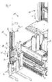
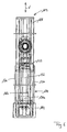
- a first embodiment of an industrial truck according to the invention is generally designated 10 in FIG. 1.
- the truck 10 has a mast 12, a thereto in the direction of the double arrow V movably arranged driver station carrier 14, arranged on the driver's seat carrier 14 side thruster 16 and one at the Side thruster 16 arranged additional stroke 18.
- the Gabelplatzica 20 carries the two forks 22 and 24, which serve as a load-handling means of the truck 10.
- the additional stroke 18 has two profile supports 26 and 28, which are essentially parallel to one another and extend in the direction of the movement direction V, which contribute to the formation of an auxiliary lifting element 19 and to which the fork carriage 20 is guided for movement in the direction of the double arrow V.
- the profile carriers 26 and 28 are arranged in the direction of the width V substantially orthogonal width direction B of the fork carrier 20 at a distance from each other, wherein between the profile beams 26 and 28, a piston-cylinder system 30 is arranged.
- the piston-cylinder system 30 has a piston or a piston rod 32, which is completely retracted in FIG. 1 into a cylinder 34 of the piston-cylinder system 30.
- the cylinder 34 of the piston-cylinder system 30 is connected by means of two transverse struts 36 and 38 with the stand 19 belonging to the additional stroke 18 profile carriers 26 and 28.
- This connection is rigid, wherein both the cylinder outer surface 34a is welded to the transverse struts 36 and 38 and the respective longitudinal ends of the transverse struts 36 and 38 are welded to the profile carriers 26 and 28.
- the cylinder 34 By this type of rigid connection of the cylinder 34 with the stator 19 of the additional stroke torsional moments about the torsion axis T, which can be introduced about dynamically when starting or braking the truck with recorded on the fork carriage 20 load in the stator 19, from the stator 19th be transferred to the cylinder 34.
- the cylinder 34 then acts as a torsion spring and stiffens the profile carrier 26 and 28 comprehensive stand 19 of the additional stroke 18 in addition.
- the torsion axis T shown in Fig. 1 coincides with the longitudinal axis L of the cylinder 34, which is ideally also the longitudinal axis of the piston-cylinder system 30.
- a bending moment is introduced into the upright 19 by the load taken and by the distance between its center of gravity and the guideways on the profile girders 26 and 28, which is about a width direction B extending bending axis W acts on the stand 19. Due to the rigid connection of the cylinder 34 with the stator 19 also such a bending moment is transmitted to the cylinder 34, so that the cylinder 34 acts as a bending spring and increases the flexural rigidity of the stator 19. Such a bending moment can be caused dynamically for a short time with a high amount, such as when the truck overruns a threshold when the load is picked up and the auxiliary lift 18 is lifted.
- the cylinder section 34b lying between the two transverse struts 36 and 38 can serve as a tension and compression rod stiffening the upright 18, which can absorb forces acting on the upright 19 along the cylinder longitudinal axis 34.
- the piston 32 is provided with a piston guide only in the region of the cylinder head 34 c, for example from the piston outlet end of the cylinder 34 to the lower edge of the upper transverse strut 36.
- Another piston guide is not provided in the piston-cylinder system 30.
- a relatively large distance between the piston outer wall and the cylinder inner wall can be held approximately in the longitudinal section 34b of the cylinder 34 located between the transverse struts 36 and 38. so that a load-related deformation of the cylinder 34 can be allowed without a retraction and / or extension movement of the piston 32 in the cylinder 34 into or out of this would be hindered.
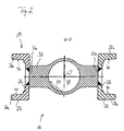
- a cross section through the stator 19 of the additional stroke 18 is shown schematically, wherein the sectional plane is orthogonal to the cylinder longitudinal axis L and the upper cross member 36 passes through.
- Guideways 40, 42, 44 and 46 are provided on the profile carriers 26 and 28 on their outer legs 26a, 26b, 28a and 28b, on which guide rollers of the fork carrier 20 for guiding the fork carrier 20, not shown in FIG. 2, roll in the direction of the double arrow V.
- the longitudinal ends 36a and 36b of the transverse strut 36 are welded to the middle limbs 26c and 28c of the profile beams 26 and 28, respectively.
- the cross strut 36 has a passage opening 48 which is penetrated by the cylinder 34, which is also not shown in Fig. 2 for the sake of clarity.
- the cross strut 36 is also welded in the region of the through hole 48 with the outer surface 34 a of the cylinder 34, as indicated by a sector of the weld 50.
- transverse strut 38 connection of the transverse strut 38 with the profile girders 26 and 28 and with the cylinder 34 is identical to the cross strut 36 described in FIG. 2, so that a separate illustration of the transverse strut 38 with reference to the description of the transverse strut 36 can be dispensed with.
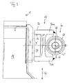
- a profile carrier 50 of the mast 12 is shown, on which the driver's seat carrier 14 is guided for adjustment along the double arrow V.
- the adjustment direction V is in Fig. 3, as in Fig. 2, orthogonal to the plane.
- the profile carrier 50 is not the only driver station carrier 14 in the adjustment direction V leading device, but that in the direction of adjustment V substantially orthogonal vehicle transverse direction Q spaced from the profile support 50 another profile support is arranged mirror-symmetrically to the illustrated.
- the adjustment force necessary for adjusting the driver position carrier 14 is provided by a further piston-cylinder system 60.
- the cylinder 64 as previously the cylinder 34 of the additional stroke 18, rigidly connected to a profile carrier 50 of the mast 52, so that a torsional about the orthogonal to the plane of Fig. 2 oriented torsion axis T ', which with the cylinder longitudinal axis L 'of the cylinder 64 coincides, from the profile carrier 50 to the cylinder 64 is transferable.
- a bending moment parallel to the roller axis R or acting around a bending axis W 'orthogonal to both the roller axis R and the torsion axis T' can be introduced into the cylinder 64 by the profile carrier 50.
- the cylinder 64 in the cylinder longitudinal direction L 'spaced apart further projections corresponding to the projections 66 and 68 of Fig. 3, so that also orthogonal to the plane of Fig. 3 acting tensile and compressive forces at least in a cylinder in the longitudinal direction L. 'located between the spaced apart projections cylinder section can be initiated.
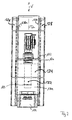
- FIGS. 4 to 7 a second embodiment of the present invention will be described below.
- the same components as in Figures 1 to 3 are provided in Figures 4 to 7 with the same reference numerals, but increased by the number 100.
- the second embodiment of Figures 4 to 7 will be described below only insofar as they differ from the first Embodiment differs, which is shown in Figures 1 to 3 and to the description of which reference is expressly made.
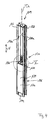
- the cylinder 134 shown in FIG. 4 is designed such that, as has already been described above, it guides the piston 132 only at the exit-side end of the cylinder 134.
- the cylinder 134 is formed by a front plate 170, a cover plate 172, which contains the guide of the piston 132 and the outlet opening of the piston 132 from the cylinder 134, a bottom plate 174 and a back plate 176 (not shown in FIG. 6).
- These mentioned plate elements 170 to 176 are welded to one another and to the profiled supports 126 and 128 of the auxiliary handle 119 such that a closed pressure-tight cavity is formed in the interior of the cylinder 134 apart from the outlet opening of the piston 132.
- Facing surfaces 126a and 128a of the profiled beams 126 and 128 formed from inexpensive U-profile semi-finished products form boundary walls of the inner volume of the cylinder 134.
- Fig. 6 is a side view of the formehub prior art 119 with integrally formed thereon cylinder 134 can be seen.
- the dashed line shows the piston 132 immersed in the cylinder interior 134a.
- a diameter extension 133 at the submerged longitudinal end of the piston 132 prevents complete expulsion of the piston 132 from the cylinder 134.
- the cylinder 134 has a supply port through which fluid can be delivered under pressure into the cylinder interior 134a to push the piston 132 out of the cylinder 134. It is likewise provided to be able to discharge the pressure of the fluid, preferably hydraulic oil, from the cylinder interior 134a in order to allow the piston 132 to be submerged in the cylinder 134.
Landscapes
- Engineering & Computer Science (AREA)
- Transportation (AREA)
- Structural Engineering (AREA)
- Civil Engineering (AREA)
- Life Sciences & Earth Sciences (AREA)
- Geology (AREA)
- Mechanical Engineering (AREA)
- Forklifts And Lifting Vehicles (AREA)
Applications Claiming Priority (1)
| Application Number | Priority Date | Filing Date | Title |
|---|---|---|---|
| DE102004042336A DE102004042336A1 (de) | 2004-09-01 | 2004-09-01 | Flurförderzeug mit starr mit Lastverlagerungsvorrichtung verbundenem Zylinder |
Publications (3)
| Publication Number | Publication Date |
|---|---|
| EP1632452A2 true EP1632452A2 (fr) | 2006-03-08 |
| EP1632452A3 EP1632452A3 (fr) | 2006-04-26 |
| EP1632452B1 EP1632452B1 (fr) | 2010-09-08 |
Family
ID=35457769
Family Applications (1)
| Application Number | Title | Priority Date | Filing Date |
|---|---|---|---|
| EP05019040A Expired - Lifetime EP1632452B1 (fr) | 2004-09-01 | 2005-09-01 | Chariot de manutention avec cylindre rigidement attaché au dispositif de déplacement de charge |
Country Status (3)
| Country | Link |
|---|---|
| US (1) | US20060104783A1 (fr) |
| EP (1) | EP1632452B1 (fr) |
| DE (2) | DE102004042336A1 (fr) |
Families Citing this family (6)
| Publication number | Priority date | Publication date | Assignee | Title |
|---|---|---|---|---|
| ES2351003B1 (es) * | 2010-06-29 | 2011-08-12 | Mecalux, S.A. | Transelevador para la manipulación de paletas, dispositivo de extracción de paletas y sistema de almacenamiento de mercancías. |
| EP2447203B1 (fr) * | 2010-11-01 | 2013-04-17 | BT Products AB | Camion industriel, procédé et programme information pour le commander |
| US9663337B2 (en) | 2014-06-26 | 2017-05-30 | Crown Equipment Corporation | Carriage assembly for materials handling vehicle and method for making same |
| DE102014216736A1 (de) | 2014-08-22 | 2016-02-25 | Jungheinrich Aktiengesellschaft | Verfahren zum Steuern einer kombinierten Dreh-Schub-Bewegung |
| US11292498B2 (en) * | 2017-08-15 | 2022-04-05 | Seegrid Corporation | Laterally operating payload handling device |
| CN110695940A (zh) * | 2019-10-18 | 2020-01-17 | 南通金牛机械制造有限公司 | 一种智能旋转多层车 |
Family Cites Families (19)
| Publication number | Priority date | Publication date | Assignee | Title |
|---|---|---|---|---|
| FR1173046A (fr) * | 1956-03-28 | 1959-02-18 | Ver Westdeutsche Waggonfab | Mât de levage pour engins de transport et de chargement |
| US3266599A (en) * | 1964-05-11 | 1966-08-16 | C H Johnson Machinery Ltd | Multi-purpose mechanical handling vehicle |
| USRE27731E (en) * | 1964-05-18 | 1973-08-14 | Triplk stage upright for lift tkuck | |
| US3362503A (en) * | 1966-02-24 | 1968-01-09 | Nautshno Izsledovatelski I Pk | Lifting means construction |
| US3709393A (en) * | 1971-01-07 | 1973-01-09 | Allis Chalmers Mfg Co | Lift truck mast |
| FR2213888A1 (fr) * | 1973-01-12 | 1974-08-09 | Coat Jean | |
| US3972388A (en) * | 1975-08-04 | 1976-08-03 | Towmotor Corporation | Lift truck mast assembly with a resilient chain positioner |
| US4355703A (en) * | 1979-03-08 | 1982-10-26 | Clark Equipment Company | Upright for lift truck |
| US4356891A (en) * | 1979-03-08 | 1982-11-02 | Clark Equipment Company | Upright for lift truck |
| US4276961A (en) * | 1979-03-12 | 1981-07-07 | Eaton Corporation | Mast and carriage assembly |
| US4503935A (en) * | 1982-03-15 | 1985-03-12 | Towmotor Corporation | Lift jack retention bracket |
| DE3333166A1 (de) * | 1983-09-14 | 1985-03-28 | Walter 7290 Freudenstadt Finkbeiner | Hebebock |
| US4625757A (en) * | 1985-06-13 | 1986-12-02 | Cobe Laboratories, Inc. | Differential pressure fluid flow regulating device |
| US4683988A (en) * | 1985-09-27 | 1987-08-04 | Shrum Jr William M | Multi-stage hydraulic drive system |
| US5011363A (en) * | 1989-12-05 | 1991-04-30 | Crown Equipment Corporation | Extend and retract control for fork lifts |
| US5447213A (en) * | 1994-06-02 | 1995-09-05 | Habicht; Helmut | Reinforced column for a lifting apparatus |
| US6505710B1 (en) * | 1997-10-14 | 2003-01-14 | Nissan Motor Co., Ltd. | Mast apparatus for fork lift trucks |
| FI111626B (fi) * | 2001-10-19 | 2003-08-29 | Rocla Oyj | Trukkimasto |
| SE522713C2 (sv) * | 2002-06-05 | 2004-03-02 | Bt Ind Ab | Anordning vid truck |
-
2004
- 2004-09-01 DE DE102004042336A patent/DE102004042336A1/de not_active Withdrawn
-
2005
- 2005-09-01 DE DE502005010206T patent/DE502005010206D1/de not_active Expired - Lifetime
- 2005-09-01 EP EP05019040A patent/EP1632452B1/fr not_active Expired - Lifetime
- 2005-09-01 US US11/217,984 patent/US20060104783A1/en not_active Abandoned
Also Published As
| Publication number | Publication date |
|---|---|
| EP1632452A3 (fr) | 2006-04-26 |
| US20060104783A1 (en) | 2006-05-18 |
| EP1632452B1 (fr) | 2010-09-08 |
| DE102004042336A1 (de) | 2006-03-02 |
| DE502005010206D1 (de) | 2010-10-21 |
Similar Documents
| Publication | Publication Date | Title |
|---|---|---|
| DE69904042T2 (de) | Energieabsorbierende vorrichtung | |
| EP0983897B1 (fr) | Dispositif de levage | |
| DE102009002613A1 (de) | Scherenhebebühne | |
| DE1531146C3 (de) | Hydraulischer Antrieb für einen Kranausleger mit teleskopartig verschiebbaren Auslegerstücken | |
| DE4016497C2 (de) | Gabelstapler mit neigbarem Hubgerüst, dessen Neigezylinder als tragendes Bauteil des Fahrzeugschutzdaches ausgebildet ist | |
| DE2018926C2 (de) | Teleskopausleger für einen Kran | |
| DE2124427C3 (de) | Anordnung einer Stoßstange an einem Kraftfahrzeug | |
| EP1632452B1 (fr) | Chariot de manutention avec cylindre rigidement attaché au dispositif de déplacement de charge | |
| DE102006029526A1 (de) | Fahrzeugaufhängungsvorrichtung | |
| DE2949047A1 (de) | Teleskop-hubmast fuer ein fahrzeug mit motorantrieb. | |
| DE2233281A1 (de) | Hubgeruest fuer einen hublader | |
| EP2799283B1 (fr) | Véhicule de transport de charge doté d'un conteneur interchangeable et d'un appareil de levage pour un conteneur interchangeable | |
| DE3423415C2 (fr) | ||
| EP2614028B1 (fr) | Dispositif de réception d'un profilé de tablier porte-fourche | |
| DE2242109B2 (de) | Lastkraftwagen mit kippbarem Führerhaus, sowie Bedienungsvorrichtung dazu | |
| EP3290264B1 (fr) | Chariot de transport | |
| DE1041864B (de) | Hubvorrichtung fuer Fahrstapler mit Freihub des Lasttraegers | |
| DE2449256A1 (de) | Maschinenrahmen | |
| DE102012001184B4 (de) | Kran mit einem Teleskopmastsystem | |
| DE2930316C2 (de) | Teleskop-Hubgerüst für Gabelstapler | |
| DE102016110138B4 (de) | Abschiebevorrichtung und Abschiebewagen mit einer Abschiebevorrichtung | |
| EP0749826B1 (fr) | Presse mécanique à genouillère | |
| DE1959735C3 (de) | Teleskopmast für Hublader mit einem gegenüber dem Standmast nach oben sowie nach unten ausfahrbaren Ausfahrmast und darin geführtem Hubschlitten | |
| DE2713808A1 (de) | Hubgeruest fuer hublader | |
| EP1046609B2 (fr) | Chariot élévateur à mât déplaçable |
Legal Events
| Date | Code | Title | Description |
|---|---|---|---|
| PUAI | Public reference made under article 153(3) epc to a published international application that has entered the european phase |
Free format text: ORIGINAL CODE: 0009012 |
|
| AK | Designated contracting states |
Kind code of ref document: A2 Designated state(s): AT BE BG CH CY CZ DE DK EE ES FI FR GB GR HU IE IS IT LI LT LU LV MC NL PL PT RO SE SI SK TR |
|
| AX | Request for extension of the european patent |
Extension state: AL BA HR MK YU |
|
| PUAL | Search report despatched |
Free format text: ORIGINAL CODE: 0009013 |
|
| AK | Designated contracting states |
Kind code of ref document: A3 Designated state(s): AT BE BG CH CY CZ DE DK EE ES FI FR GB GR HU IE IS IT LI LT LU LV MC NL PL PT RO SE SI SK TR |
|
| AX | Request for extension of the european patent |
Extension state: AL BA HR MK YU |
|
| 17P | Request for examination filed |
Effective date: 20060731 |
|
| 17Q | First examination report despatched |
Effective date: 20060925 |
|
| AKX | Designation fees paid |
Designated state(s): DE FR GB IT SE |
|
| GRAP | Despatch of communication of intention to grant a patent |
Free format text: ORIGINAL CODE: EPIDOSNIGR1 |
|
| GRAS | Grant fee paid |
Free format text: ORIGINAL CODE: EPIDOSNIGR3 |
|
| GRAA | (expected) grant |
Free format text: ORIGINAL CODE: 0009210 |
|
| AK | Designated contracting states |
Kind code of ref document: B1 Designated state(s): DE FR GB IT SE |
|
| REG | Reference to a national code |
Ref country code: GB Ref legal event code: FG4D Free format text: NOT ENGLISH |
|
| REF | Corresponds to: |
Ref document number: 502005010206 Country of ref document: DE Date of ref document: 20101021 Kind code of ref document: P |
|
| REG | Reference to a national code |
Ref country code: SE Ref legal event code: TRGR |
|
| PLBE | No opposition filed within time limit |
Free format text: ORIGINAL CODE: 0009261 |
|
| STAA | Information on the status of an ep patent application or granted ep patent |
Free format text: STATUS: NO OPPOSITION FILED WITHIN TIME LIMIT |
|
| 26N | No opposition filed |
Effective date: 20110609 |
|
| REG | Reference to a national code |
Ref country code: DE Ref legal event code: R097 Ref document number: 502005010206 Country of ref document: DE Effective date: 20110609 |
|
| REG | Reference to a national code |
Ref country code: FR Ref legal event code: PLFP Year of fee payment: 11 |
|
| PGFP | Annual fee paid to national office [announced via postgrant information from national office to epo] |
Ref country code: GB Payment date: 20150930 Year of fee payment: 11 |
|
| PGFP | Annual fee paid to national office [announced via postgrant information from national office to epo] |
Ref country code: SE Payment date: 20150928 Year of fee payment: 11 |
|
| PGFP | Annual fee paid to national office [announced via postgrant information from national office to epo] |
Ref country code: IT Payment date: 20150925 Year of fee payment: 11 Ref country code: DE Payment date: 20151130 Year of fee payment: 11 |
|
| PGFP | Annual fee paid to national office [announced via postgrant information from national office to epo] |
Ref country code: FR Payment date: 20150930 Year of fee payment: 11 |
|
| REG | Reference to a national code |
Ref country code: DE Ref legal event code: R119 Ref document number: 502005010206 Country of ref document: DE |
|
| PG25 | Lapsed in a contracting state [announced via postgrant information from national office to epo] |
Ref country code: SE Free format text: LAPSE BECAUSE OF NON-PAYMENT OF DUE FEES Effective date: 20160902 |
|
| REG | Reference to a national code |
Ref country code: SE Ref legal event code: EUG |
|
| GBPC | Gb: european patent ceased through non-payment of renewal fee |
Effective date: 20160901 |
|
| REG | Reference to a national code |
Ref country code: FR Ref legal event code: ST Effective date: 20170531 |
|
| PG25 | Lapsed in a contracting state [announced via postgrant information from national office to epo] |
Ref country code: FR Free format text: LAPSE BECAUSE OF NON-PAYMENT OF DUE FEES Effective date: 20160930 Ref country code: GB Free format text: LAPSE BECAUSE OF NON-PAYMENT OF DUE FEES Effective date: 20160901 Ref country code: DE Free format text: LAPSE BECAUSE OF NON-PAYMENT OF DUE FEES Effective date: 20170401 |
|
| PG25 | Lapsed in a contracting state [announced via postgrant information from national office to epo] |
Ref country code: IT Free format text: LAPSE BECAUSE OF NON-PAYMENT OF DUE FEES Effective date: 20160901 |