EP1631976B1 - Steuereinrichtung des trommeltyps mit mehreren schaltwegen und mit solchen einrichtungen ausgestattetes elektronisches gerät - Google Patents
Steuereinrichtung des trommeltyps mit mehreren schaltwegen und mit solchen einrichtungen ausgestattetes elektronisches gerät Download PDFInfo
- Publication number
- EP1631976B1 EP1631976B1 EP04741785A EP04741785A EP1631976B1 EP 1631976 B1 EP1631976 B1 EP 1631976B1 EP 04741785 A EP04741785 A EP 04741785A EP 04741785 A EP04741785 A EP 04741785A EP 1631976 B1 EP1631976 B1 EP 1631976B1
- Authority
- EP
- European Patent Office
- Prior art keywords
- drum
- trigger
- housing
- switching
- shaft
- Prior art date
- Legal status (The legal status is an assumption and is not a legal conclusion. Google has not performed a legal analysis and makes no representation as to the accuracy of the status listed.)
- Expired - Lifetime
Links
- 230000009471 action Effects 0.000 claims abstract description 8
- 238000006073 displacement reaction Methods 0.000 claims description 42
- 239000004020 conductor Substances 0.000 claims description 21
- 238000007373 indentation Methods 0.000 claims description 10
- 230000035807 sensation Effects 0.000 claims description 9
- 230000002093 peripheral effect Effects 0.000 claims description 7
- 239000004033 plastic Substances 0.000 claims description 7
- 229920003023 plastic Polymers 0.000 claims description 7
- 230000000295 complement effect Effects 0.000 claims description 6
- 230000000694 effects Effects 0.000 claims description 6
- 230000006870 function Effects 0.000 description 19
- 210000003811 finger Anatomy 0.000 description 9
- 230000033001 locomotion Effects 0.000 description 7
- 238000007789 sealing Methods 0.000 description 7
- 230000008859 change Effects 0.000 description 6
- 238000000465 moulding Methods 0.000 description 6
- 239000000463 material Substances 0.000 description 5
- 238000009434 installation Methods 0.000 description 4
- 230000003071 parasitic effect Effects 0.000 description 4
- 238000002788 crimping Methods 0.000 description 3
- 230000010354 integration Effects 0.000 description 3
- 239000002184 metal Substances 0.000 description 3
- 230000008901 benefit Effects 0.000 description 2
- 230000015572 biosynthetic process Effects 0.000 description 2
- 238000001514 detection method Methods 0.000 description 2
- 238000001746 injection moulding Methods 0.000 description 2
- 230000007246 mechanism Effects 0.000 description 2
- 238000000034 method Methods 0.000 description 2
- 230000035945 sensitivity Effects 0.000 description 2
- 239000004809 Teflon Substances 0.000 description 1
- 229920006362 Teflon® Polymers 0.000 description 1
- 239000000654 additive Substances 0.000 description 1
- 230000000996 additive effect Effects 0.000 description 1
- 230000003466 anti-cipated effect Effects 0.000 description 1
- 230000003190 augmentative effect Effects 0.000 description 1
- 239000011248 coating agent Substances 0.000 description 1
- 238000000576 coating method Methods 0.000 description 1
- 230000000994 depressogenic effect Effects 0.000 description 1
- 238000011161 development Methods 0.000 description 1
- 230000018109 developmental process Effects 0.000 description 1
- 229920001971 elastomer Polymers 0.000 description 1
- 239000000806 elastomer Substances 0.000 description 1
- 239000013536 elastomeric material Substances 0.000 description 1
- 238000001125 extrusion Methods 0.000 description 1
- 230000006872 improvement Effects 0.000 description 1
- 238000004519 manufacturing process Methods 0.000 description 1
- 239000002991 molded plastic Substances 0.000 description 1
- 239000012778 molding material Substances 0.000 description 1
- 238000010619 multiway switching Methods 0.000 description 1
- 230000008447 perception Effects 0.000 description 1
- -1 polytetra-fluoro-ethylene Polymers 0.000 description 1
- 239000004810 polytetrafluoroethylene Substances 0.000 description 1
- 229940058401 polytetrafluoroethylene Drugs 0.000 description 1
- 238000003825 pressing Methods 0.000 description 1
- 230000004044 response Effects 0.000 description 1
- 210000003813 thumb Anatomy 0.000 description 1
- 230000016776 visual perception Effects 0.000 description 1
- 230000002747 voluntary effect Effects 0.000 description 1
- 238000003466 welding Methods 0.000 description 1
Images























Classifications
-
- H—ELECTRICITY
- H01—ELECTRIC ELEMENTS
- H01H—ELECTRIC SWITCHES; RELAYS; SELECTORS; EMERGENCY PROTECTIVE DEVICES
- H01H9/00—Details of switching devices, not covered by groups H01H1/00 - H01H7/00
- H01H9/02—Bases, casings, or covers
- H01H9/04—Dustproof, splashproof, drip-proof, waterproof, or flameproof casings
-
- H—ELECTRICITY
- H01—ELECTRIC ELEMENTS
- H01H—ELECTRIC SWITCHES; RELAYS; SELECTORS; EMERGENCY PROTECTIVE DEVICES
- H01H19/00—Switches operated by an operating part which is rotatable about a longitudinal axis thereof and which is acted upon directly by a solid body external to the switch, e.g. by a hand
- H01H19/005—Electromechanical pulse generators
-
- H—ELECTRICITY
- H01—ELECTRIC ELEMENTS
- H01H—ELECTRIC SWITCHES; RELAYS; SELECTORS; EMERGENCY PROTECTIVE DEVICES
- H01H25/00—Switches with compound movement of handle or other operating part
- H01H25/008—Operating part movable both angularly and rectilinearly, the rectilinear movement being perpendicular to the axis of angular movement
-
- H—ELECTRICITY
- H01—ELECTRIC ELEMENTS
- H01H—ELECTRIC SWITCHES; RELAYS; SELECTORS; EMERGENCY PROTECTIVE DEVICES
- H01H19/00—Switches operated by an operating part which is rotatable about a longitudinal axis thereof and which is acted upon directly by a solid body external to the switch, e.g. by a hand
- H01H19/02—Details
- H01H19/10—Movable parts; Contacts mounted thereon
- H01H19/14—Operating parts, e.g. turn knob
- H01H2019/146—Roller type actuators
Definitions
- the present invention relates to a control device.
- the invention relates, more particularly, to an electric control device having multiple switching or commutation ways or channels, especially of the tactile feedback or touch-working type.
- the invention relates to a device by which distinct electrical switching operations can be performed by means of a sole actuating member for the purpose, for example, of controlling a function of an electronic appliance ensuing from choices made by selection from a menu or a display screen list.
- a device employing a single control member by which, on the one hand, electrical signals or pulses repeated at high frequency and, on the other hand, unitary signals, for example enabling signals, can be produced, and this with an ergonomy for the user which is perfectly tailored to this type of operation, that is to say which allows him to produce repeated pulses quickly and easily, for example for the purpose of performing a rapid scan of a menu or list and then producing enabling signals.
- a multiple switch of this kind is especially desirable for a multiple switch of this kind to be made operable with the thumb by being installed on the main front face of the telephone comprising, in particular, the keypad, either on one of the two main side edges of the housing of the telephone, or under the main face of the telephone.
- control device or navigator is used within the framework of a game.
- the tactile sensation or feedback transmitted by the device to the user of the navigator is a very important parameter for his performances and his ergonomy.
- the sensitivity of touch of the user is such that it allows him to perceive very fine, discrete or continuous variations, and that it is thus possible to transmit a very complex "message" to the finger or hand of the user.
- the finger is thus an issuer of orders (or transmitter) for displacing the cursor on the screen and/or for selecting a position of the cursor, and it is also a sensor (or receiver) which picks up "blind" tactile information returned through the actuator or control member without the user, therefore, having to look at the screen, and/or in addition to his visual perceptions.
- such messages or tactile sensations are, for example, pulses or mechanical "clicks" corresponding to each electrical signal or pulse produced by the navigator and destined for the electronic circuits for processing signals or data of the appliance, or corresponding to series of pulses.
- a control device of the type comprising a plastics housing accommodating a revolving horizontal shaft which is capable of being rotated, in both directions, by a manual driving drum supported or borne by the shaft to which it is rotationally linked, of the type in which the shaft is rotationally linked to at least one rotary member belonging to a generator of control signals or pulses for an electronic appliance, especially for controlling the displacements of a cursor on a display screen of the appliance, and of the type in which the shaft is mounted such that it is vertically movable and tiltable in both directions about a transverse horizontal axis orthogonal to the longitudinal axis of the shaft so as to selectively provoke the triggering:
- control drum is mounted such that it revolves relative to an intermediate plate which is hinged-mounted relative to the housing or fixed support and the movements of which are controlled by action upon the control drum.
- US-B1-6.211.474 illustrates another design in which the drum rests vertically on a central member which bears upon the bottom of the housing and which, from a rest position, is elastically deformable.
- the different trigger members are individual and distinct, for example elastic domes which preclude a major miniaturization of the device.
- the invention proposes a device of the aforementioned type, characterized in that said central member is a common conductive trigger which belongs to the said three switching ways, which bears upon the bottom of the housing and which, from said rest position, is selectively elastically deformable under the action of one of the said forces of vertical orientation.
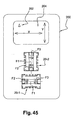
- the invention also proposes an electronic appliance characterized in that it comprises a display screen and two devices in accordance with the teachings of the invention for controlling the displacements of a cursor on the screen along two perpendicular displacement axes (X, Y), and in that the two devices are disposed such that the rotational axes of the control members of the two devices are orthogonal and parallel to the said displacement axes, respectively.
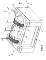
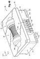
- the device 20 comprises a lower housing 22 in the general shape of a substantially parallelepipedal rectangle, the upper face 24 of which is upwardly open, and an upper closing lid 26 for the lower housing, which latter houses the principal components of the device 20.
- These components comprise, in the first embodiment both from the bottom up and in the bottom of the housing 22, two left T2 and right T3 horizontal, transverse fixed contact rods, two rear T4 and front T5 horizontal, longitudinal fixed contact rods and a fixed central contact ball 28, as well as a movable contact rod T6 belonging to a rotary signals generator associated with the longitudinal rods T4 and T5.
- a central trigger member 30 in the general shape of a star having four trigger branches Bi, a sole or single manual control member 32 of longitudinal and horizontal rotation axis Z-Z and a flat sealing joint 34.
- the sole manual control member 32 which is here realized molded in a one single piece, is basically constituted by a rotary operating drum 36, the central section 38 of which is of reduced diameter, and of inwardly curved or concave profile, relative to its two knurled longitudinal end sections, left 40 and right 42 (not represented), or is lined with a "soft"-feeling elastomer outer skin (not represented).
- the drum 36 is designed to be rotated by its slender central part 38, which, for this purpose, can comprise longitudinal ribs (not represented in this embodiment).
- the control member 32 also comprises a central shaft, which is extended, beyond the longitudinal end side left and right faces 35, 37 of the drum 36, by two longitudinal end sections, left 44 and right 46, for the rotation-mounting and guiding-mounting of the member 32 in the lower housing 22, which, for this purpose, comprises two median vertical and longitudinal slots, left 48 and right 50, which emerge vertically in the upper face 24 and each of which receives, in rotational and vertically sliding arrangement, the corresponding section 44, 46 respectively.
- the slots 48 and 50 also provide for the longitudinal, play-free positioning of the control member 32 relative to the housing 22.
- the control device or navigator 20 is here a device having five switching ways, each of which can be used independently of the others through the application of a corresponding force Fi to the control member 32.
- the first switching way is a so-called "SELECT" way, which is used by applying of a centered vertical force F1 to the central section 38 of the drum 36, by which, for example, a set position reached by a cursor on a flat screen of an electronic appliance (see, for example, Figure 45 ) equipped with the navigator 32 can be selected or enabled, each application of a vertical force F1 allowing a selection signal or pulse to be produced or generated.
- SELECT so-called "SELECT" way, which is used by applying of a centered vertical force F1 to the central section 38 of the drum 36, by which, for example, a set position reached by a cursor on a flat screen of an electronic appliance (see, for example, Figure 45 ) equipped with the navigator 32 can be selected or enabled, each application of a vertical force F1 allowing a selection signal or pulse to be produced or generated.
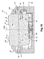
- the second switching way is, for example, a so-called "LEFT" displacement way for displacement towards the left of the screen, which is used by applying a vertical force F2 to the left section 40 of the drum 36, each application of a vertical force F2 allowing a "LEFT” displacement signal or pulse to be produced ( Figure 19 ).
- the third switching way is, for example, a so-called "RIGHT” displacement way for displacement towards the right of the screen, which is used by applying a vertical force F3 to the right section 42 of the drum 36, each application of a vertical force F3 allowing a "RIGHT” displacement signal or pulse to be produced ( Figure 20 ).
- the circuits of the operated electronic appliance can provide that, if the user keeps the drum “pressed” down according to F2 or F3, the pulses are repeated in continuous trains of identical pulses ("Scrolling"), in the same way as for a computer keyboard on which the key or button is kept pressed.
- the fourth switching way is, for example, a so-called "DOWN" displacement way for displacement towards the bottom of the screen, which is used by applying to the central part 38 of the drum 36 a circular force F4 tending to rotate it in a first direction or sense so as to generate a series of control signals or pulses by means of a signals generator 52 which will be described below.
- the fifth switching way is, for example, a so-called "UP" displacement way for displacement towards the top of the screen, which is used by applying to the drum 36 a circular force F5 tending to rotate it in a second direction or sense so as to generate a series of control signals or pulses by means of the signals generator.
- the application of the forces F2 or F3 to the drum 36 might be facilitated by the presence of the knurls at its ends 40 and 42, which indicate to the user that they are zones on which it is necessary to press. However, as it will be seen later with respect to the last embodiment, these zones might also be flush without knurls, the knurls being preferably arranged in the central potion for rotational driving.
- the general concept of the device according to the invention with its single actuator or control member 32 does permit to have different values for the central SELECT force F1 and the lateral LEFT, or RIGHT force F2, or F3 in a ratio between 1,5 to 2. This is due to the possibility to dimension the drum and its various central and lateral 40, 42 actuating zones along the longitudinal axis, as well as the dimensions of the switching branches of the a central trigger member 30.
- any vertical or substantially vertical effort applied to the central concave section or portion 38 of the drum member is inherently an effort of the F1 type which does provoke a switching of the first way.
- any effort applied on the lateral left or right section (40 or 42) is inherently an effort of the F2 or F3 type which does provoke a corresponding switching of the second or third way.
- the navigator 20 has a general design symmetry relative to the median vertical and longitudinal plane PLM in which is situated the rotational axis X-X of the drum member 32, and a general symmetry relative to the median vertical and transverse plane PTM, with the exception of the means, constituting the signals generator 52, which are here gathered together in the right-hand part of the housing 22 and which have no symmetrical counterpart in the left-hand part of the housing.
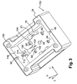
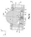
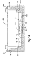
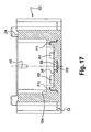
- the flat horizontal bottom 56 of the housing 22 contains a receptacle 58, which receives the central metallic ball 28, the upper section of which, in the form of a convex spherical cap, projects vertically above the plane 56.
- the ball 28 cooperates with a common, fixed, central contact pad P0, which is connected, by a strip conductor (or conducting strip) 60 (see Figure 9 ), to a connecting terminal in the form of a pin or lug C0, which projects transversely forward in a receptacle 21 in the lower part of the front longitudinal face 23 of the housing 22.
- Each fixed transverse contact rod T2, T3 is in the form of a pin and is mounted in the bottom of the housing, bearing upon two left front 62 and rear 64 and right front 66 and rear 68 positioning and fixing side feet, containing vertical slots and raised in the bottom 56.
- the front feet 62 and 66 respectively comprise a second P2 and a third P3 fixed conductor pad, each of which is electrically connected to the fixed contact rod T2, T3.
- Each pad P2, P3 is connected, by a strip conductor 70, 72, to a connecting pin or lug C2, C3.
- the bottom 56 also comprises two front 74 and rear 76 central feet, which, in the plane PTM, are aligned with the ball 28.
- Each central foot constitutes a part of a first fixed conductor pad P1 and these parts are connected, here by a common strip conductor 78, to a common connecting pin or lug C1.
- the common trigger member 30 allows the first switching way between the pads P0 and P1, the second switching way between the pads P0 and P2 (through the fixed contact rod T2), or the third switching way between the pads P0 and P3 (through the fixed contact rod T3), to be selectively established, and this as a function of the vertical force F1, F2 or F3 applied to the drum 36 by the user, i.e. as depending upon the force which is applied.
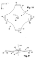
- the common trigger member 30, here made of metal integrates or gathers four trigger members, each of which is constituted by a trigger branch Bi, of essentially radial orientation, which extends outwards from a central portion 80 of essentially domed shape and the concavity of which is orientated vertically upwards.
- These four branches Bi are identical and are angularly distributed at 90° apart such that the member 30 has a design symmetry about its vertical central axis Y-Y, which, in position mounted in the housing, corresponds to the intersection of the planes PLM and PTM.
- the bottom 84 of the central part 80 comprises a receptacle 82 in the form of a spherical cap, the concavity of which is orientated downwards and the radius of which is substantially equal to that of the ball 28 such as to rest on the latter (see Figure 12 ) and allow slight pivotal movements of the member 30 about the center of the ball 28.
- the receptacle 82 can be truncated in such a way as to secure a circular contact with the ball 28.
- the member 30 comprises two diametrically opposed longitudinal branches, left B2 and right B3, which will be referred to as the second trigger branch B2 and third trigger branch B3 and which belong to the second and third switching ways respectively.
- the member 30 also comprises two first transverse trigger branches B1, which are diametrically opposed and belong to the first switching way.
- Each trigger branch B1 extends slightly upwards and their free ends are substantially coplanar.
- each free end 86, 88 of the branch B2, B3 extends above and at a distance from the associated fixed transverse contact rod T2, T3.
- each free end 90 of the branch B1 (front, rear) extends above and at a distance from a first fixed contact pad P1.
- the drum 76 rests vertically on the upper faces of the free ends 86 and 88 of the longitudinal trigger branches B2 and B3.
- the latter are slightly elastically pretensioned in the downward direction and thus permanently ensure an elastic return function of the drum 36 towards its high rest position illustrated in the figures, in which position the longitudinal end sections 44 and 46 bear upwards against the lower face of mutually opposite portions 92 and 94 of the sealing joint 34, which "close" the slots or receptacle 48 and 50 in the upward direction.
- each upper face of a free end 86, 88 slides along a cylindrical annular path or track 41, 43, respectively, in the periphery of the drum, these being adjacent to the knurled lateral end sections 40 and 42.
- the design of the member 30 and of its branches Bi is such that, when the free end of a branch Bi is stressed by applying to it, from top to bottom, a substantially vertical force, the branch is elastically deformed, then suddenly changes of position, angling downwards, this sudden change allowing the securement of a trigger function, for the purpose of establishing at least the corresponding switching way, and supplying, moreover, a click of tactile and/or auditory sensation indicating the sudden change of position.
- the left longitudinal branch B2 becomes sufficiently deformed to change state in order for its free end to come into electrical contact with the rod T2, as illustrated in Figures 19 and 21 .
- This deformation of the considered B2 branch is combined with a rotational movement or tilting of the central trigger member 30 around the center of the ball 28.
- the second electrical switching way (28-P0, B2, 86, T2, P2) between the terminals C0 and C2 is thus established through the common member 30, which is conductive and which, by its central part, is always in contact with the central fixed contact 28-P0, which is common to the first three switching ways.
- the tracks 41 and 43 of the drum 36 act simultaneously and symmetrically upon the free ends of the two longitudinal branches B2 and B3.
- the "doubling" of the branches B1 and of the pads P1 is redundant insofar as the sudden change of state of the two branches is virtually simultaneous, but this redundancy provides a high level of working reliability.
- an action of the F1 type might also provoke the switching between the free ends of the lateral branches B2 and B3 with the corresponding fixed contacts T2 and T3.
- the associated software will permit to analyze the various received signals with a view to discriminating the quasi simultaneous switching of the second and third ways hereabove mentioned, from the consecutive switching of these two second and third ways due to a consecutive and voluntary action on one and thereafter the other lateral end portion of the drum member.
- the first switching way when applying an F1 effort might not use the branches B1 and the associated fixed contacts, but only the quasi simultaneous formation of switching pulses or signals on the second and third ways, as described above, in combination with the corresponding analysis and discrimination by means of the associated software.
- the signals generator 52 will now be described, the general design of which is that described and represented in document WO-A-02/075641 and in document FR-A-2.844.619 and in French patent application n° 0306475 of 28 May 2003 .
- the generator 52 comprises a toothed spur-type driving pinion 100 , which is rotationally linked to the shaft between the end section 46 and the opposite end face 37 of the drum 36.
- a toothed spur-type driving pinion 100 which is rotationally linked to the shaft between the end section 46 and the opposite end face 37 of the drum 36.
- an upper section 104 of the movable contact rod T6 in rest position is received in such a way as to provoke the tilting of the movable contact rod T6 in either direction (F4, F5) when the shaft is rotated by the drum 36 in order to establish an electrical contact between the movable contact rod T6 and one or other of the two fixed longitudinal contact rods T4, T5 and thus to generate a control signal, and such as then to provoke the automatic escape of the upper section 104 from the space delimited by the two consecutive teeth beyond a set angle of rotation of the associated drive shaft.
- the movable contact rod T6 is a bent-wire element, which extends in a vertical plane and which, when the generator is at rest, lies in the plane PLM.
- Such a design of a movable rod has been described and represented in document WO-A-02/075641 ( Figures 25 to 29 ).
- It is basically composed of a vertical strand, comprising an upper section 106 and a lower section 108 connected by a horizontal intermediate section 110 constituting the horizontal general tilt axis of the movable contact rod T6.
- the horizontal section is received in the bottom of a slot 112 formed in the upper face of a foot 114 adjacent to the right-hand inner side face 116 of the housing 22.
- the vertical strand 106-108 is extended rightwards, from the lower end of the lower section 108, by a longitudinal horizontal strand 118 which is received in the bottom of a triangular recess 120 hollowed out in the bottom 56 and the free end 122 of which, bent back 180°, is clamped in a longitudinal vertical slot 124.
- the bottom of this slot 124 comprises a conductor pad P6, which is connected, by a strip conductor 126, to an output terminal C6 to which the movable contact rod T6 is thus permanently electrically connected.
- This design incorporating the horizontal strand 118 produces a high return motion stiffness, whilst the ohmic resistance of the wire section of the rod is very small between, on the one hand, the "crossed" point of contact between the lower section 108 and the fixed rod T4 (or T5) and, on the other hand, the contact pad P6.
- the fixed longitudinal contact rods T4 and T5 are each squeezed by their left-hand longitudinal end 128, 130, bent back 180°, into a slot in a rear foot 132, front foot 134, and each extends longitudinally and horizontally in overhang above the bottom of the recess 120.
- each rod T4, T5 is deformable elastically and transversely outwards. This is therefore a case of an advantageous crosspoint contact with accompaniment, which avoids the phenomena of bounce, allows the force variations as a function of production tolerances to be minimized and hence produces a high level of homogeneity in the forces to be applied to the drum.
- each slot comprises an associated conductor pad P4, P5, which is connected by a strip conductor 136, 138 to an output terminal C4, C5 respectively.
- the rod tilts about its horizontal axis 110, in the manner of a crankshaft, and its lower end proceeds to establish an electrical contact with the corresponding fixed rod T4 or T5.
- the fourth switching way (C6, T6, T4, C4) or the fifth switching way (C6, T6, T5, C5) is thus established according to the direction of rotation.
- the lower horizontal section 118 clamped at its right-hand end, secures the elastic return of the movable rod T6 into its rest position.
- the association of the rotary generator 52 with the multiple-branched Bi trigger member 30 is particularly advantageous and allows the realization of a very compact assembly with a reduced number of components, yet the low total height of which offers access to a large portion of the drum emerging above the upper face of the lid 26.
- the left longitudinal end 44 of the shaft also bears a left toothed pinion 144.
- this second pinion can also belong to a second, dual-way rotary signals generator analogous to the generators 52, the components of which are in this case arranged on the left-hand part of the housing 22 under the pinion 144.
- a second such generator may be necessary for the redundancy-based reliability of the device or as a function of a specific application inherent to the electronic appliance.
- the pinions 144 and 100 are received with play in semicylindrical receptacles 146 and 148 formed in the lower face 150 of the lid, which, with the upper face 24 of the housing 22, encloses the upper joint 34.
- the components assembly is held in place by closure of the lid 26, which is fixed by hot crimping of the studs 152 of the housing 22, which pass through holes 154 in the lid 26.
- the first seal in the top part is secured by the joint 34 with its cutout 93, which closely matches the profile of the drum 36 (35, 40, 41, 38, 43, 42, 37).
- the joint can also, be realized by bi-injection molding with the lid.
- the film 170 is held in position by an upper peripheral frame 172, which rests on a peripheral inner shoulder 154 on which the periphery of the sealing joint can be glued.
- the sealing film 170 thus extends vertically between the drum 36 and the common trigger member 30.
- the drum in this case comprises two circular ribs or flanges 41 and 43, axially facing the upper faces of the ends 36 and 38 of the branches B2 and B3.
- each flange rubs on the part opposite the upper part of the film 170, which can be provided with a top coating (not represented) of low friction coefficient, for example "Teflon” (polytetra-fluoro-ethylene).
- the film 170 can be totally or partially transparent or translucid.
- the film 170 provides a virtually total sealing of the lower part of the housing 22 with only a very small cut-out in its right-hand transverse edge having a transverse slot 174 for the passage and deflections of the movable contact rod T6, the upper control portion 104 of which extends above the film 170 so as to cooperate with the driving pinion 100.
- the longitudinal cylindrical body of the spring 156 is received and guided in a complementary receptacle 166 in the housing 22.
- the length and the number of turns of the spring allow, in particular, the value of the elastic return force to be gauged.
- the ohmic resistance between the lower movable contact section 108 and the fixed pad P6 is greater than previously.
- the housing 22, as in the case of the aforementioned “trackballs”, can also comprise inner lighting diodes 176 for the drum 36, which can be totally or partially translucid.
- Such illuminating means in association with the tactile sensations, allow the user to be supplied with luminous indications, especially for the purpose of guiding him in his use of the device, for example so as to indicate to him the type of force he must apply to the drum for the next executable function.
- the drum 36 can comprise a translucid body 180 having molded-on opaque axial end sections 182, with the molding material extending longitudinally into the radial slots or notches 178 in the translucid body 180.
- a series of angularly evenly distributed luminous windows are defined, which are equal in number, for example, to the number of teeth of the driving pinion.
- drum a known material, of the phosphorescent type, which permits to very quickly accumulate light from the external environment and to restitute this light during several hours.
- This material might be in the form of an additive in an elastomeric soft-touch material.
- the drum might be permanently and slightly illuminated so as to facilitate its detection by the user in the same manner as an illuminated button or switch for equipment of the dashboard.
- the second (F2) and third (F3) switching ways can be used for "large-step” rapid displacements upwards and downwards, whereas the fourth (F4) and fifth (F5) switching ways retain their "fine-step” control function.
- a first drum device 20-1 can in this case be used for X-axis displacements and a second device 20-2 to control the Y-axis displacements, the axes of both drums being perpendicular by virtue of a "T"-shaped (as in Figure 45 ) or "L"-shaped arrangement.
- the first device arranged “horizontally” (parallel to the horizontal axis of the "X's” on the screen), can secure the control of all the "X-axis” displacements with displacements according to a large step (F2, F3) or according to a fine step (F4, F5) in both directions (leftwards or rightwards).
- the second device arranged “vertically” (parallel to the vertical axis of the "Y's” on the screen), can secure the control of all the "Y-axis” displacements with displacements according to a large step (F2, F3) or according to a fine step (F4, F5) in both directions (leftwards or rightwards).
- Each of the devices has, moreover, a supplementary enabling switching way (F1).
- the first, “horizontally” arranged device can control the "X-axis” displacements in large steps (F2, F3) and the “Y-axis” displacements (F4, F5) in fine steps
- the second, “vertically” arranged device controls the "Y-axis” displacements in large steps (F2, F3) and the "X-axis” displacements in fine steps (F4, F5).
- the tracks connecting the pads Pi to the terminals Ci are advantageously realized in the form of pre-cut tracks, constituting inserts around which the plastics insulating body of the housing 22 is molded on.
- the device 20 according to the second embodiment has design symmetry about the central vertical axis corresponding to the interception of the aforementioned planes PLM and PTM.
- the signals generator 52 is thus constituted by two identical generators 52 arranged on the left and on the right and each of which comprises a movable contact rod T6, the lower section 108 of which cooperates, by its free lower end 109, with a fixed pad P4 (on the right), P5 (on the left) arranged in the bottom 56, which bottom is constituted, for example, by a conductive inset.
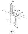
- the rod T6 is connected to the last turn 158 of a helical spring 156 which secures its return into its angular position of rest and the axis Z-Z of which constitutes the pivot axis in both directions of the movable contact rod and lies parallel to the rotational axis X-X of the drum.
- the two rectilinear sections 106 and 108 and the upper loop 104 bent back 180° (which is received between the teeth 102 of the pinion 100), extend in an axial plane which, in the angular position of rest of the rod T6, forms an angle relative to the vertical.
- the longitudinal cylindrical body of the spring 156 is received and guided in a complementary receptacle 166 in the housing 22.
- the length and the number of turns of the spring allow, in particular, the value of the elastic return force to be gauged.
- the double signals generator works as follows.
- the right-hand driving pinion 100 provokes the repeated formation of signals or pulses by repeated contacting of the end 109 of the movable contact rod T6, which is essentially driven downwards so as to cooperate with the fixed contact pad P4.
- the user thus uses the fourth switching way.
- the equidirectional rotation of the left-hand pinion 100 provokes corresponding movements of the left-hand movable contact rod T6, but its free end shifts essentially upwards without, however, entering into electrical contact with the lower, fixed contact pad P5.
- a rotary signals generator 52 having a single switching way on each side of the housing eliminates the risk of generating parasitic pulses when the first three switching ways are actuated, since the descent of a pinion 100 provokes a tilting of the rod(s) T6, but in a direction which tends to remove its lower contact end 109 from the associated conductor pad P4 or P5.
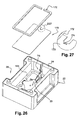
- the upper closing lid 26 is extending longitudinally and transversely beyond the vertical planes of the lateral faces, such as the front and rear longitudinal faces 23 and 25 and transversal faces 27, of the lower housing 22 thus defining a lower peripheral and horizontal edge surface 210.
- the housing 22 also comprises protruding horizontal ribs 212 defining a horizontal upper bearing surface 214.
- the connecting terminals Ci made of conductive material and extending outside of the housing 22 are in the form of contacting blades which are elastically deformable, each of them extending upwardly in a corresponding receptacle 216 formed in the the lateral face 23.
- the receptacles 216 are separated by isolating intermediary walls 220.
- Each blade Ci defines a contacting outer face 218. Each blade Ci can be transversely depressed in the direction of the face 23.
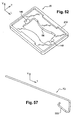
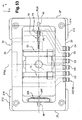
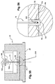
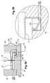
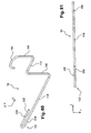
- Each left T2 and right T3 horizontal, transverse fixed contact rod such as the one T3 illustrated in details on figures 57 to 59 , comprises a curved bent front end 222, 223 which is crimped in a corresponding shaft or well 224, 225 (in the form of a vertical and transversal slot which is open upwardly) equivalent to previous feet 62 and 66, each having in its bottom a conductive pad P3, P2 respectively of L shaped cross section.
- Each transverse rod T2, T3 is thus mounted in a cantilevered fashion such as a beam with its free rear end 226, 227 bearing, in an elastical pre-stressed state, against a horizontal lower bearing surface 228, 229.
- This improvement provides for a more precise and trustable detection of the corresponding switching and is particularly advantageous when using the simultaneous or quasi-simultaneous switching of the second and third ways (in association with the corresponding software) to detect a central SELECT action of the F1 type (as previously described in connection with the first embodiment).
- Each rod by means of its main central section, thus precisely defines a horizontal contact with which the lower face of the corresponding branch B2, B3 comes into contact, each rod T2, T3 being thereafter freely and elastically deformable downwardly under the action of the drum when either force F3 or F2 is applied.
- the mobile contact rod T6 is basically composed of a vertical strand, comprising an upper section 106 and a lower section 108 connected by a horizontal intermediate section 110 constituting the horizontal general tilt axis of the movable contact rod T6 which, for this purpose, is received in the bottom of a V shaped slot 112 formed in the upper face of a foot 114 adjacent to the right-hand inner side face 116 of the housing 22.
- the vertical strand 106-108 is extended, from the lower end of the lower section 108, by a longitudinal horizontal strand 118 which is here suspended parallelly to the bottom of a recess 120 hollowed out in the bottom 56.
- the free end 122 of the rod T6 which, bent back at 180° in the form of a horizontal hairpin, is clamped in a longitudinal vertical slot 124.
- the bottom of the slot 124 comprises a conductor pad P6, which is connected, by a strip conductor 126, to the output terminal C6 to which the movable contact rod T6 is thus permanently electrically connected.
- the clamping of the hairpin loop or end 122 of the rod T6 is ensured by means of a rib 230 formed in the upper strand 232 of the looped end 122 and which extends transversely in order to be force fitted in the facing internal longitudinal wall of the vertical slot 124.
- the crimping or clamping is such that the lower strand 234 of the looped end 122 is permanently and elastically pre-stressed in electrical contact with the contacting pad P6.
- looped end 122 does constitute an embedded end so that a kind of torque does permanently apply the intermediate section 110 in the V shaped slot 110.
- the crimping might also be reinforced by hot welding of the upper part of the slot 164 co totally embed the end 122 in the loop.
- the two rear T4 and front T5 horizontal, longitudinal fixed contact rods have been replaced by conductive metallic pads P4(T4) and T6(P6) on which the lower housing is overmoulded.
- the rod tilts about its horizontal axis 110, in the manner of a crankshaft, and its lower end 108 proceeds to establish an electrical contact with the corresponding fixed pad P4 or P5.
- the longitudinal left end side face 35 of the drum 36 is provided with a toothed wheel 236 here comprising eight hollow indentations 238 separated by eight V shaped convex teeth 240.
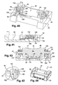
- the wheel 236 is rotatably linked to the drum 36 so that an indentation 238 is downwardly oriented in a vertical plane when an interdental space 140 between two consecutive teeth 102 is also similarly oriented, i.e. when the upper portion of the mobile contact rod T6 is in rest position (see figures 62 to 64 ).
- the wheel 236 is cooperating with an elastic indexing V shaped convex finger 242 which extends longitudinally and horizontally towards the right.
- the wheel 236 in combination with the finger 242 does form a kind of ratchet wheel and pawl mechanism.
- the indexing finger or pawl 242 belongs to an elastic indexing blade 244 which is supported by the lower housing 22 so as to provide a detent effect when cooperating successively with the indentations 238 and teeth 240 of the ratchet wheel 236.
- the finger 242 In the rest position (see for instance figures 54 and 55 ) the finger 242 is received in a hollow or concave indentation 238 of the wheel 236.
- each indentation 238 is delimitated by two lateral inclined (5° to 8°)opposed faces 237 and 239 so as to have a V shape opening radially towards the exterior.
- the V profile of the indentation 238 does provide a return spring or elastic effect acting on the drum vertically and upwardly.
- the arrangement of the pawl and ratchet mechanism does provide the user with a tactile and/or audio sensation when the drum reaches a new angular rest position which also corresponds to a rest position of the pulse generator 100-T6.
- the audio or tactile signal is generated when an electrical pulse is generated.
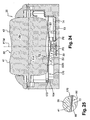
- the drum 32 is made of several parts contrarily to the first embodiment ( fig. 24 ) where the drum 32 is a single molded piece.
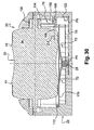
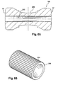
- the drum 36 is thus made of a main tubular and cylindrical molded body 180 having a central axial tubular hole which receives a central shaft 252 which might be made of plastics or of metal and which is rotatably linked to the main body 180.
- the two opposite ends of the central shaft 252 each comprises an axial open hole which receives an end rod constituting two longitudinal end sections, left 44 and right 46, for the rotation-mounting and guiding-mounting of the member 32 in the lower housing 22, which, for this purpose, comprises two median vertical and longitudinal slots, left 48 and right 50, which emerge vertically in the upper face 24 and each of which receives, in rotational and vertically sliding arrangement, the corresponding section 44, 46 respectively.
- the driving pinion 100 and the wheel 236 are for instance metallic parts which are force fitted on the end rods 46 and 44.
- the wheel 236 might also be made in a single piece with the central shaft 252.
- all the components 180, 252, 44, 46, 100 and 236 might be realized in the form of a single molded plastics piece, depending on the dimensions, efforts to be supported, life length, etc.
- the central or mid portion of the drum 36 is here of concave shape and comprises series of axial knurls 264 to provide the user with additional tactile information and to improve its "gripping" of the drum for rotating it and also for applying the "enabling" effort F1 and the lateral end portions are here flush.
- the knurls 264 might be realized directly by molding with the main body 180. However, the number of knurls is thus necessarily reduced due to the molding techniques.
- the previously mentioned one piece molding of the drum easily permits to define an angular and precise orientation of the knurls 264 with respect to the pinion 100 and the wheel 236 which already have a respective mutual angular orientation as previously mentioned.
- the number of the knurls is reduced and similar to the number of teeth 102 and indentations 238 which is generally comprised between six and twelve, and also depending on the overall external diameter of the drum, it is possible to orientate a hollow between two indentations 264 upwardly in the vertical plane PLM and also an opposite lower one facing the branches B2 and B3, when the drum is in its angular rest position previously mentioned.
- knurls 264 are preferably made in an independent sheath or tubular mantle 266 made by molding of an elastomeric material. This because it is then not possible to realize the knurls in the concave mid portion by molding techniques.
- the sheath 266 is extrusion molded independently and then the body is introduced therethrough elastically and temporarily deforming the sheath 266 illustrated in figure 66 .
- the sheath is thus received in the external complementary groove 268 of the main body 180.
- the sheath 266 can also be realized by bi-injection molding with the body 180.
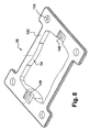
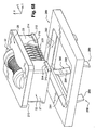
- the frame 280 delimitates a central opening 282 which is rectangular and complementary to the external shape of the upper lid 26.
- the lower peripheral and horizontal edge surface 210 of the lid 26 is bearing downwardly on a facing upper peripheral and horizontal edge 284 of the opening 280 thus defining the vertical position of the lid with respect to the frame 280.
- the frame, or wall portion, 280 of the apparatus equipped with the multiway switching device comprises a number (four in the illustrated example) of elastic arms 286 which extend freely downwardly and each of them having a free lower end 288 which bears on the corresponding surface 214 of the lower body 22.
- Each locking arm 286 is ramp shaped so as to automatically escape by elastical deformation when the device is vertically introduced for mounting in the opening 280, downwardly when considering figure 68 .
- the internal ramp shaped face 290 of each arm 286 cooperates with the corresponding portion of a facing rib 212.
- the device 20 is fully locked and positioned with respect to the frame 280 (see also figure 54 on which the frame 280 has been represented).
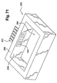
- the latter may comprise a hollow body, a portion 292 of which is illustrated on figures 71 and 72 .
- the body 292 defines a rectangular parallepipedal vertical hole 294 which opens in its upper face 296 and which is adapted to receive the device 20.
- the internal longitudinal face 298 of the central hole 294 comprises a series of conductive tracks 300, each of which being positioned and arranged to cooperate with a corresponding blade or terminal Ci-218 of the device 20 (see figure 72 ).
- Each track 300 is preferably one face of a conductive metal strip 302 on which the plastic body 292 is overmoulded and which constitutes a fixed contact pin for electrical connection.
- the lid 26 might be made by molding as a single piece with the upper wall or frame 280, thus simplifying assembly and also permitting to suppress the elastic locking arms 286.
Landscapes
- Switches With Compound Operations (AREA)
- Position Input By Displaying (AREA)
- Mechanical Control Devices (AREA)
- Facsimile Scanning Arrangements (AREA)
- Invalid Beds And Related Equipment (AREA)
- Operating, Guiding And Securing Of Roll- Type Closing Members (AREA)
- Display Devices Of Pinball Game Machines (AREA)
- Selective Calling Equipment (AREA)
- Control Of Multiple Motors (AREA)
Claims (25)
- Steuereinrichtung (20) mit einem Kunststoffgehäuse (22), das eine sich drehende, horizontale Welle (44, 46) aufweist, die in beide Richtungen durch eine manuelle Antriebstrommel (36) gedreht werden kann, welche von der Welle abgestützt wird, mit der sie drehbar verbunden ist,- der Art, dass die Welle drehbar mit mindestens einem Drehelement (100) verbunden ist, das zu einem Generator (52) von Steuersignalen oder Impulsen für ein elektronisches Gerät gehört, besonders zur Steuerung der Verschiebungen eines Cursors auf einem Display oder Bildschirm des Gerätes,- der Art, dass die Welle derart montiert ist, dass sie vertikal verschiebbar ist und in beide Richtungen um eine querverlaufende, horizontale Achse orthogonal zu der Längsachse (X-X) der Welle geneigt werden kann, so dass die Auslösung folgender Elemente selektiv hervorgerufen werden kann:- eines ersten Trigger-Elementes, das zu einem ersten Schaltwerg gehört, wenn eine Kraft (F1) vertikaler Ausrichtung im wesentlichen auf die Mitte (38) der Trommel (36) angewendet wird;- eines zweiten Trigger-Elementes, das zu einem zweiten Schaltweg gehört, wenn eine Kraft (F2) vertikaler Ausrichtung in der Nähe einer (40) der beiden Längsenden der Trommel (36) angewendet wird;- eines dritten Trigger-Elementes, das zu einem dritten Schaltweg gehört, wenn eine Kraft ( F3) vertikaler Ausrichtung in der Nähe des anderen (42) der beiden Längsenden der Trommel (36) angewendet wird;- und der Art, bei der die Trommel (36, 41, 43) vertikal auf einem mittleren Element (30) ruht, das auf dem Boden (56, 28) des Gehäuses (22) aufliegt, und das aus einer Ruheposition heraus elastisch verformbar ist,dadurch gekennzeichnet, dass es sich bei dem mittleren Element (30, B1, B2, B3) um ein allgemein übliches, leitfähiges Trigger-Element handelt, das zu den drei Schaltwegen gehört, und das aus der Ruheposition heraus unter der Wirkung einer der Kräfte (F1, F2, F3) vertikaler Ausrichtung selektiv elastisch verformbar ist.
- Einrichtung nach Anspruch 1, dadurch gekennzeichnet, dass jedes Trigger-Element des gemeinsamen Elementes (30) ein Triggerzweig (B1, B2, B3) ist, der sich radial von einem mittleren Abschnitt (80) erstreckt, der vertikal auf dem Boden (56, 58, 28) des Gehäuses aufliegt.
- Einrichtung nach Anspruch 2, dadurch gekennzeichnet, dass es sich bei dem zweiten und dritten Trigger-Element um einen zweiten (B2) und dritten (B3) Triggerzweig aus leitfähigem Material handelt, die diametral gegenüberliegen und in Längsrichtung fluchten, und von denen jeder selektiv elastisch verformbar ist, und zwar aus einer stabilen, hohen Ruheposition in eine niedrige Schaltposition, so dass jeder (B2, B3) eine elektrische Verbindung zwischen zwei Kontakten eines Paares verbundener, fester Kontakte ([P0, 28], [T2, P2] - [P0, 28], [T3, P3] bildet, die im Boden (56) des Gehäuses (22) angeordnet sind, von denen einer ([T2, P2], [T3, P3]) im wesentlichen vertikal in Bezug auf das freie Ende (86, 88) des zugehörigen Triggerzweiges (B2, B3) angeordnet ist.
- Einrichtung nach Anspruch 3, dadurch gekennzeichnet, dass die Umfangsfläche (41,43) jedes der gegenüberliegenden, axialen Endabschnitte der Trommel (36) vertikal auf der Oberseite des freien Endes eines der zweiten (B2) und dritten (B3) Triggerzweige ruht.
- Einrichtung nach dem vorhergehenden Anspruch, dadurch gekennzeichnet, dass das Gehäuse Führungselemente (48, 50) zur Führung der gegenüberliegenden, axialen Enden (44, 46) der Welle in einer vertikalen Ebene (PLM) senkrecht zu dem Boden (56) des Gehäuses aufweist.
- Einrichtung entweder nach Anspruch 4 oder Anspruch 5, dadurch gekennzeichnet, dass die Trommel durch den zweiten und dritten Triggerzweig elastisch in eine hohe Ruheposition zurückgeführt wird.
- Einrichtung nach einem der Ansprüche 3 bis 6, dadurch gekennzeichnet, dass es sich bei dem ersten Trigger-Element um einen Triggerzweig (B1) aus leitfähigem Material handelt, der sich radial von dem mittleren Abschnitt (80) in eine querverlaufende Richtung (T) im wesentlichen orthogonal zu der Längsrichtung (L) des zweiten und dritten Triggerzweiges (B2, B3) erstreckt, und der aus einer stabilen und hohen Ruheposition in eine niedrige Schaltposition elastisch verformbar ist, so dass eine elektrische Verbindung zwischen zwei Kontakten eines Paares verbundener, fester Kontakte ([P0, 28], P1) hergestellt wird, die im Boden (56) des Gehäuses (22) angeordnet sind, und von denen einer (P1) im wesentlichen vertikal in Bezug auf das freie Ende (90) des ersten Triggerzweiges (B1) angeordnet ist.
- Einrichtung nach Anspruch 7, dadurch gekennzeichnet, dass das erste Trigger-Element zwei erste, diametral gegenüberliegende Triggerzweige (B1) aus leitfähigem Material besitzt, die sich radial von dem mittleren Abschnitt (80) erstrecken, und die gleichzeitig elastisch verformbar sind, und zwar aus einer stabilen und hohen Ruheposition in eine niedrige Schaltposition, so dass jeweils eine elektrische Verbindung zwischen mindestens zwei feststehenden Kontakten eines Paares verbundener, fester Kontakte, die in dem Boden des Gehäuses angeordnet sind, hergestellt wird, von denen einer im wesentlichen vertikal in Bezug auf das freie Ende des verbundenen ersten Triggerzweiges angeordnet ist.
- Einrichtung nach einem der Ansprüche 3 bis 6, dadurch gekennzeichnet, dass das erste Trigger-Element aus der Verbindung der zweiten und dritten Trigger-Elemente (B2, B3) besteht, wobei ihre Schaltung gleichzeitig oder im wesentlichen gleichzeitig bewirkt wird, wenn die Kraft (F1) mit einer vertikalen Ausrichtung im wesentlichen auf die Mitte (38) der Trommel (36) ausgeübt wird.
- Einrichtung nach einem der Ansprüche 3 bis 9, dadurch gekennzeichnet, dass jeder Triggerzweig (Bi) über eine eingestellte Bewegung hinaus plötzlich seinen Zustand ändert, so dass er an den Benutzer der Einrichtung (20) über die Trommel (36) eine Tastempfindung der Auslösung (triggering) übermittelt.
- Einrichtung nach einem der Ansprüche 2 bis 10, dadurch gekennzeichnet, dass der mittlere Abschnitt (80), von dem aus die Triggerzweige (Bi) verlaufen, ein gewölbter Abschnitt ist, dessen Konkavität nach oben gerichtet ist, so das der mittlere Bereich (84) seiner konvexen Unterseite vertikal auf dem Boden (56, 28) des Gehäuses aufliegt.
- Einrichtung nach dem vorhergehenden Anspruch, dadurch gekennzeichnet, dass jeder Triggerzweig (Bi) von dem gewölbten mittleren Abschnitt (80) aus radial nach außen und nach oben verläuft.
- Einrichtung nach Anspruch 11 oder Anspruch 12, dadurch gekennzeichnet, dass der mittlere Bereich des gewölbten mittleren Abschnittes (80) einen Abschnitt in Form einer sphärischen oder kegelstumpfartigen, insbesondere konkaven Kappe (82) aufweist, die vertikal auf einem weiteren Abschnitt (28) im Boden (56, 58) des Gehäuses aufliegt, so dass sie ein Zentrier- und/oder Gelenkelement für den mittleren Abschnitt (80) darstellt.
- Einrichtung nach einem der Ansprüche 3 bis 10, dadurch gekennzeichnet, dass der mittlere Abschnitt (80) aus leitfähigem Material besteht, und mit einem gemeinsamen, feststehenden, elektrischen Kontakt (P0) elektrisch verbunden ist, der zu jedem Paar verbundener, fester Kontakte gehört ([P0, 28], [T2, P2] - [P0, 28], [T3, P3] - P0, P1) .
- Einrichtung nach einem der vorhergehenden Ansprüche, dadurch gekennzeichnet, dass es sich bei dem Drehelement um ein Antriebszahnrad (100) handelt, das mit der Welle drehbar verbunden ist, und in der Nähe eines (46) der axialen Enden der Welle angeordnet ist, und zwischen zwei aufeinanderfolgenden Zähnen (102) der Trommel wird ein oberer Abschnitt (104) eines beweglichen Kontaktstabes (T6) aufgenommen, um das Kippen des Kontaktstabes (T6) in die eine oder andere Richtung hervorzurufen, wenn die Welle durch die Trommel (36) gedreht wird, um (F4, F5) einen vierten (P0, P4) und/oder einen fünften Schaltweg (P5) zwischen dem beweglichen Kontaktstab (T6, 108) und einem feststehenden, vierten (T4) oder fünften Kontakt (T5) festzulegen, so dass der obere Abschnitt (104) dann automatisch aus dem Raum heraustritt, der von den beiden aufeinanderfolgenden Zähnen (102) begrenzt wird, und zwar über einen eingestellten Drehwinkel der Antriebswelle hinaus.
- Einrichtung nach dem vorhergehenden Anspruch, dadurch gekennzeichnet, dass jede längsverlaufende Stirnseite der Antriebswelle ein Antriebszahnrad (100) aufweist, das mit der Welle drehbar verbunden ist, und zwischen zwei aufeinanderfolgenden Zähnen (102) dieses Antriebszahnrades wird ein oberer Abschnitt (104) eines verbundenen, beweglichen Kontaktstabes (T6) aufgenommen, um das Kippen des Kontaktstabes in die eine oder andere Richtung zu bewirken, wenn die Welle durch die Trommel (36) gedreht wird, um einen (F4, F5) vierten (P0, P4) und/oder einen fünften Schaltweg (P0, P5) zwischen dem Kontaktstab (T6, 108, 109) und einem feststehenden vierten oder fünften Kontakt festzulegen, so dass der obere Abschnitt dann automatisch aus dem Raum heraustritt, der von den beiden aufeinanderfolgenden Zähnen begrenzt wird, und zwar über einen eingestellten Drehwinkel der Antriebswelle hinaus.
- Einrichtung nach Anspruch 16, dadurch gekennzeichnet, dass sich der bewegliche Kontaktstab (T6) im wesentlichen in einer axialen, vertikalen Ebene (PLM) unter dem Antriebszahnrad (100) erstreckt.
- Steuereinrichtung nach Anspruch 15, dadurch gekennzeichnet, dass sich der bewegliche Kontaktstab (T6) im wesentlichen in einer axialen Ebene erstreckt, die in Bezug auf die Vertikale um ungefähr 45° geneigt ist.
- Steuereinrichtung nach Anspruch 15, dadurch gekennzeichnet, dass der bewegliche Kontaktstab einen unteren, vertikalen Kontaktabschnitt (108) aufweist, der in einer querverlaufenden, vertikalen Ebene beweglich ist, welche sich längs durch einen horizontalen Abschnitt (118) erstreckt, der eine Rückholfeder bildet, dessen freies Ende (122, 124) immobilisiert ist, und mit einer feststehenden Kontaktunterlage (P6) des Gehäuses in elektrischem Kontakt steht.
- Einrichtung nach einem der vorhergehenden Ansprüche, dadurch gekennzeichnet, dass sie Beleuchtungsvorrichtungen (176) für die Trommel besitzt, die in dem Boden (56) des Gehäuses (22) angeordnet sind, und dass die Trommel (36) vollständig oder teilweise lichtdurchlässig oder transparent ist, um das von den Beleuchtungsvorrichtungen (176) übertragene Licht weiterzuleiten.
- Einrichtung nach einem der vorhergehenden Ansprüche, dadurch gekennzeichnet, dass sie ein Schaltrad (236) besitzt, das mit einem seitlichen Ende der Antriebstrommel (36) drehbar verbunden ist, sowie eine feststehende Sperrklinke (242, 244), die von dem Kunststoffgehäuse (22) gehalten wird, und Audioimpulse und/oder Tastimpulse erzeugt, wenn die Trommel gedreht wird.
- Einrichtung nach dem vorhergehenden Anspruch, dadurch gekennzeichnet, dass die Sperrklinke elastisch ist, und dass sie die Trommel im Zusammenwirken mit den Vertiefungen (238) des Schaltrades (236) mit einem Effekt der elastischen Umkehr nach oben versieht, nachdem das entsprechende seitliche Ende der Trommel vertikal nach unten verschoben worden ist.
- Elektronisches Gerät (200), dadurch gekennzeichnet, dass es ein Display bzw. einen Bildschirm und zwei Steuereinrichtungen (20-1, 20-2) jeweils nach Anspruch 15 zur Steuerung der Bewegungen eines Cursors (202) auf dem Bildschirm entlang zweier senkrechter Verschiebungsachsen (X, Y) aufweist, und dass die beiden Einrichtungen (20) derart angeordnet sind, dass die Drehachsen der Steuerelemente (32, 36) der beiden Einrichtungen orthogonal bzw. parallel zu den Verschiebungsachsen angeordnet sind.
- Elektronisches Gerät nach dem vorhergehenden Anspruch, dadurch gekennzeichnet, dass der zweite, dritte, vierte und fünfte Schaltweg jeder Einrichtung (20-1, 20-2) entlang derselben Achse (X-Achse oder Y-Achse) mit der Steuerung der Bewegungen des Cursors (202) verbunden ist.
- Elektronisches Gerät nach Anspruch 23, dadurch gekennzeichnet, dass der zweite und dritte Schaltweg einer ersten (20-1) der beiden Einrichtungen mit der Steuerung der Bewegungen des Cursors entlang einer Achse (X-Achse) verbunden ist, und der vierte und fünfte Schaltweg der ersten Einrichtung (20-1) mit der Steuerung der Bewegungen des Cursors entlang der anderen Achse (Y-Achse) verbunden ist, und dass der zweite und dritte Schaltweg der zweiten (20-2) der beiden Einrichtungen mit der Steuerung der Bewegungen des Cursors entlang der anderen Achse (Y-Achse) verbunden ist, und der vierte und fünfte Schaltweg der zweiten Einrichtung (20-2) mit der Steuerung der Bewegungen des Cursors entlang der einen Achse (X-Achse) verbunden ist.
Applications Claiming Priority (2)
| Application Number | Priority Date | Filing Date | Title |
|---|---|---|---|
| FR0306972A FR2856191B1 (fr) | 2003-06-11 | 2003-06-11 | Dispositif de commande a tambour et a voies de commutation multiples, et appareil electronique equipe de tels dispositifs |
| PCT/EP2004/051095 WO2004112070A1 (en) | 2003-06-11 | 2004-06-11 | Drum-type control device having multiple switching ways and electronic appliance equipped with such devices |
Publications (2)
| Publication Number | Publication Date |
|---|---|
| EP1631976A1 EP1631976A1 (de) | 2006-03-08 |
| EP1631976B1 true EP1631976B1 (de) | 2009-04-01 |
Family
ID=33484321
Family Applications (1)
| Application Number | Title | Priority Date | Filing Date |
|---|---|---|---|
| EP04741785A Expired - Lifetime EP1631976B1 (de) | 2003-06-11 | 2004-06-11 | Steuereinrichtung des trommeltyps mit mehreren schaltwegen und mit solchen einrichtungen ausgestattetes elektronisches gerät |
Country Status (10)
| Country | Link |
|---|---|
| US (1) | US7528331B2 (de) |
| EP (1) | EP1631976B1 (de) |
| JP (1) | JP2006527471A (de) |
| KR (1) | KR20060026003A (de) |
| CN (2) | CN101414526A (de) |
| AT (1) | ATE427553T1 (de) |
| CA (1) | CA2504522A1 (de) |
| DE (1) | DE602004020335D1 (de) |
| FR (1) | FR2856191B1 (de) |
| WO (1) | WO2004112070A1 (de) |
Families Citing this family (11)
| Publication number | Priority date | Publication date | Assignee | Title |
|---|---|---|---|---|
| FR2856191B1 (fr) | 2003-06-11 | 2005-07-22 | Itt Mfg Enterprises Inc | Dispositif de commande a tambour et a voies de commutation multiples, et appareil electronique equipe de tels dispositifs |
| FR2874739B1 (fr) * | 2004-09-01 | 2006-10-20 | Itt Mfg Enterprises Inc | Dispositif perfectionne de commande a tambour et a voies de commutation multiples |
| US7860538B2 (en) * | 2006-02-28 | 2010-12-28 | Lg Electronics Inc. | Mobile terminal |
| US7996050B2 (en) * | 2006-02-28 | 2011-08-09 | Lg Electronics Inc. | Input device for an electronic device and electronic device having the same |
| DE102006039386A1 (de) * | 2006-08-22 | 2008-03-27 | BSH Bosch und Siemens Hausgeräte GmbH | Bedienvorrichtung für ein elektrisches Gerät |
| DE102006039384A1 (de) * | 2006-08-22 | 2008-03-20 | BSH Bosch und Siemens Hausgeräte GmbH | Bedienvorrichtung für ein elektrisches Gerät |
| CN201025520Y (zh) * | 2007-03-06 | 2008-02-20 | 鸿富锦精密工业(深圳)有限公司 | 电脑面板 |
| FR2973932A1 (fr) * | 2011-04-06 | 2012-10-12 | Peugeot Citroen Automobiles Sa | Dispositif de commutation a double element d'actionnement rotatif pour volant de vehicule et volant comprenant un tel dispositif de commutation |
| US10671179B2 (en) * | 2015-12-30 | 2020-06-02 | Shenzhen Royole Technologies Co., Ltd. | Rollable and flexible input device |
| CN108550337B (zh) * | 2018-06-13 | 2023-12-29 | 深圳市深科达智能装备股份有限公司 | 模组自动点灯治具载台 |
| DE102023135596A1 (de) | 2023-12-18 | 2025-06-18 | Valeo Schalter Und Sensoren Gmbh | Bedienvorrichtung für ein Kraftfahrzeug mit drückbarem Bedienrad und Haptik-Aktuator, Kraftfahrzeug und Verfahren zum Betätigen einer Bedienvorrichtung |
Family Cites Families (10)
| Publication number | Priority date | Publication date | Assignee | Title |
|---|---|---|---|---|
| JP3437054B2 (ja) * | 1997-05-12 | 2003-08-18 | アルプス電気株式会社 | 多入力スイッチ |
| JP3951485B2 (ja) * | 1998-12-25 | 2007-08-01 | 松下電器産業株式会社 | 回転・押圧操作型電子部品およびそれを用いた電子機器 |
| FR2792486B1 (fr) * | 1999-04-16 | 2001-05-18 | Itt Mfg Enterprises Inc | Commutateur electrique multiple a tambour unique d'actionnement |
| JP3952642B2 (ja) * | 1999-09-20 | 2007-08-01 | 松下電器産業株式会社 | 押圧・回転操作型電子部品 |
| ATE253770T1 (de) | 2000-01-14 | 2003-11-15 | Sonion As | 3d-rollschlüssel |
| EP1182852A1 (de) * | 2000-08-24 | 2002-02-27 | Sony International (Europe) GmbH | Tragbares Kommunikationsgerät mit verbesserter Auswahlvorrichtung |
| FR2822271B1 (fr) | 2001-03-16 | 2003-05-02 | Itt Mfg Enterprises Inc | Dispositif a boule de commande des deplacements d'un curseur sur un ecran d'appareil electronique |
| EP1444712A2 (de) * | 2001-11-12 | 2004-08-11 | Methode Electronics, Inc. | Elektromechanischer impulsgenerator mit einem zahnkranzartigen drehbaren nockenrad |
| FR2840447B1 (fr) | 2002-05-30 | 2004-11-26 | Itt Mfg Entpr S Inc | Commutateur electrique miniaturise a voies multiples de commutation |
| FR2856191B1 (fr) | 2003-06-11 | 2005-07-22 | Itt Mfg Enterprises Inc | Dispositif de commande a tambour et a voies de commutation multiples, et appareil electronique equipe de tels dispositifs |
-
2003
- 2003-06-11 FR FR0306972A patent/FR2856191B1/fr not_active Expired - Fee Related
-
2004
- 2004-06-11 AT AT04741785T patent/ATE427553T1/de not_active IP Right Cessation
- 2004-06-11 CN CNA2008102130767A patent/CN101414526A/zh active Pending
- 2004-06-11 WO PCT/EP2004/051095 patent/WO2004112070A1/en not_active Ceased
- 2004-06-11 JP JP2006516148A patent/JP2006527471A/ja not_active Withdrawn
- 2004-06-11 CN CNA2004800015976A patent/CN1717762A/zh active Pending
- 2004-06-11 EP EP04741785A patent/EP1631976B1/de not_active Expired - Lifetime
- 2004-06-11 CA CA002504522A patent/CA2504522A1/en not_active Abandoned
- 2004-06-11 KR KR1020057015941A patent/KR20060026003A/ko not_active Withdrawn
- 2004-06-11 DE DE602004020335T patent/DE602004020335D1/de not_active Expired - Lifetime
-
2005
- 2005-11-16 US US11/285,657 patent/US7528331B2/en not_active Expired - Lifetime
Also Published As
| Publication number | Publication date |
|---|---|
| US7528331B2 (en) | 2009-05-05 |
| EP1631976A1 (de) | 2006-03-08 |
| CN1717762A (zh) | 2006-01-04 |
| WO2004112070A1 (en) | 2004-12-23 |
| CA2504522A1 (en) | 2004-12-23 |
| JP2006527471A (ja) | 2006-11-30 |
| CN101414526A (zh) | 2009-04-22 |
| KR20060026003A (ko) | 2006-03-22 |
| DE602004020335D1 (de) | 2009-05-14 |
| FR2856191A1 (fr) | 2004-12-17 |
| US20060109244A1 (en) | 2006-05-25 |
| ATE427553T1 (de) | 2009-04-15 |
| FR2856191B1 (fr) | 2005-07-22 |
Similar Documents
| Publication | Publication Date | Title |
|---|---|---|
| US5952628A (en) | Multiple-way electronic component with push switch | |
| EP1631976B1 (de) | Steuereinrichtung des trommeltyps mit mehreren schaltwegen und mit solchen einrichtungen ausgestattetes elektronisches gerät | |
| EP1026713B1 (de) | Elektronische teilen mit druck und rotations betätigung und kommunikationsendstellengerät | |
| US6720504B2 (en) | Multi-operational electronic device | |
| US7297883B2 (en) | Electrical switch with multiple switching ways | |
| CN100533625C (zh) | 开关装置 | |
| CN100492571C (zh) | 旋转按压操作型电子元件及使用它的电子设备 | |
| JP4238085B2 (ja) | 多方向スイッチ | |
| EP1028446B1 (de) | Kombinierter Druckknopf- und Drehschalter | |
| WO2003046822A1 (en) | Manoeuvring device for control of user functions in an electronic appliance endowed with a display | |
| JP4359478B2 (ja) | ジョイスティック型スイッチ装置 | |
| JPH1167016A (ja) | 複合操作型電気部品 | |
| KR19980070244A (ko) | 복합 조작형 스위치 | |
| CN1937129A (zh) | 开关装置 | |
| US5378862A (en) | Universal pivot switch with a hemispheric pivotal support member | |
| KR20060002749A (ko) | 다기능성 스위치 소자 | |
| KR101759320B1 (ko) | 비접촉식 복합 스위치 | |
| JP2942098B2 (ja) | 多方向入力装置 | |
| JPH11203985A (ja) | 電子機器および回転・押圧操作型電子部品 | |
| US6396016B1 (en) | Electronic component incorporating push switch and rotary encoder | |
| EP1632968A1 (de) | Verbesserte Steuereinrichtung mit einer Trommel und mit mehreren Schaltungskanalen | |
| JP3880756B2 (ja) | スイッチ装置 | |
| JP3763044B2 (ja) | 多方向スイッチ | |
| JP4063753B2 (ja) | ジョイスティック型入力装置 | |
| JPH11162299A (ja) | 多機能型操作要素 |
Legal Events
| Date | Code | Title | Description |
|---|---|---|---|
| PUAI | Public reference made under article 153(3) epc to a published international application that has entered the european phase |
Free format text: ORIGINAL CODE: 0009012 |
|
| 17P | Request for examination filed |
Effective date: 20050428 |
|
| AK | Designated contracting states |
Kind code of ref document: A1 Designated state(s): AT BE BG CH CY CZ DE DK EE ES FI FR GB GR HU IE IT LI LU MC NL PL PT RO SE SI SK TR |
|
| DAX | Request for extension of the european patent (deleted) | ||
| 17Q | First examination report despatched |
Effective date: 20061227 |
|
| RAP1 | Party data changed (applicant data changed or rights of an application transferred) |
Owner name: COACTIVE TECHNOLOGIES, INC. |
|
| GRAP | Despatch of communication of intention to grant a patent |
Free format text: ORIGINAL CODE: EPIDOSNIGR1 |
|
| GRAP | Despatch of communication of intention to grant a patent |
Free format text: ORIGINAL CODE: EPIDOSNIGR1 |
|
| GRAS | Grant fee paid |
Free format text: ORIGINAL CODE: EPIDOSNIGR3 |
|
| GRAA | (expected) grant |
Free format text: ORIGINAL CODE: 0009210 |
|
| AK | Designated contracting states |
Kind code of ref document: B1 Designated state(s): AT BE BG CH CY CZ DE DK EE ES FI FR GB GR HU IE IT LI LU MC NL PL PT RO SE SI SK TR |
|
| REG | Reference to a national code |
Ref country code: GB Ref legal event code: FG4D |
|
| REG | Reference to a national code |
Ref country code: CH Ref legal event code: EP |
|
| REG | Reference to a national code |
Ref country code: IE Ref legal event code: FG4D |
|
| REF | Corresponds to: |
Ref document number: 602004020335 Country of ref document: DE Date of ref document: 20090514 Kind code of ref document: P |
|
| PG25 | Lapsed in a contracting state [announced via postgrant information from national office to epo] |
Ref country code: SI Free format text: LAPSE BECAUSE OF FAILURE TO SUBMIT A TRANSLATION OF THE DESCRIPTION OR TO PAY THE FEE WITHIN THE PRESCRIBED TIME-LIMIT Effective date: 20090401 |
|
| NLV1 | Nl: lapsed or annulled due to failure to fulfill the requirements of art. 29p and 29m of the patents act | ||
| PG25 | Lapsed in a contracting state [announced via postgrant information from national office to epo] |
Ref country code: ES Free format text: LAPSE BECAUSE OF FAILURE TO SUBMIT A TRANSLATION OF THE DESCRIPTION OR TO PAY THE FEE WITHIN THE PRESCRIBED TIME-LIMIT Effective date: 20090712 Ref country code: EE Free format text: LAPSE BECAUSE OF FAILURE TO SUBMIT A TRANSLATION OF THE DESCRIPTION OR TO PAY THE FEE WITHIN THE PRESCRIBED TIME-LIMIT Effective date: 20090401 Ref country code: PT Free format text: LAPSE BECAUSE OF FAILURE TO SUBMIT A TRANSLATION OF THE DESCRIPTION OR TO PAY THE FEE WITHIN THE PRESCRIBED TIME-LIMIT Effective date: 20090902 Ref country code: FI Free format text: LAPSE BECAUSE OF FAILURE TO SUBMIT A TRANSLATION OF THE DESCRIPTION OR TO PAY THE FEE WITHIN THE PRESCRIBED TIME-LIMIT Effective date: 20090401 Ref country code: AT Free format text: LAPSE BECAUSE OF FAILURE TO SUBMIT A TRANSLATION OF THE DESCRIPTION OR TO PAY THE FEE WITHIN THE PRESCRIBED TIME-LIMIT Effective date: 20090401 |
|
| PG25 | Lapsed in a contracting state [announced via postgrant information from national office to epo] |
Ref country code: NL Free format text: LAPSE BECAUSE OF FAILURE TO SUBMIT A TRANSLATION OF THE DESCRIPTION OR TO PAY THE FEE WITHIN THE PRESCRIBED TIME-LIMIT Effective date: 20090401 Ref country code: SE Free format text: LAPSE BECAUSE OF FAILURE TO SUBMIT A TRANSLATION OF THE DESCRIPTION OR TO PAY THE FEE WITHIN THE PRESCRIBED TIME-LIMIT Effective date: 20090701 Ref country code: PL Free format text: LAPSE BECAUSE OF FAILURE TO SUBMIT A TRANSLATION OF THE DESCRIPTION OR TO PAY THE FEE WITHIN THE PRESCRIBED TIME-LIMIT Effective date: 20090401 |
|
| PG25 | Lapsed in a contracting state [announced via postgrant information from national office to epo] |
Ref country code: MC Free format text: LAPSE BECAUSE OF NON-PAYMENT OF DUE FEES Effective date: 20090630 Ref country code: CZ Free format text: LAPSE BECAUSE OF FAILURE TO SUBMIT A TRANSLATION OF THE DESCRIPTION OR TO PAY THE FEE WITHIN THE PRESCRIBED TIME-LIMIT Effective date: 20090401 Ref country code: DK Free format text: LAPSE BECAUSE OF FAILURE TO SUBMIT A TRANSLATION OF THE DESCRIPTION OR TO PAY THE FEE WITHIN THE PRESCRIBED TIME-LIMIT Effective date: 20090401 Ref country code: RO Free format text: LAPSE BECAUSE OF FAILURE TO SUBMIT A TRANSLATION OF THE DESCRIPTION OR TO PAY THE FEE WITHIN THE PRESCRIBED TIME-LIMIT Effective date: 20090401 |
|
| REG | Reference to a national code |
Ref country code: CH Ref legal event code: PL |
|
| PLBE | No opposition filed within time limit |
Free format text: ORIGINAL CODE: 0009261 |
|
| STAA | Information on the status of an ep patent application or granted ep patent |
Free format text: STATUS: NO OPPOSITION FILED WITHIN TIME LIMIT |
|
| PG25 | Lapsed in a contracting state [announced via postgrant information from national office to epo] |
Ref country code: SK Free format text: LAPSE BECAUSE OF FAILURE TO SUBMIT A TRANSLATION OF THE DESCRIPTION OR TO PAY THE FEE WITHIN THE PRESCRIBED TIME-LIMIT Effective date: 20090401 Ref country code: BE Free format text: LAPSE BECAUSE OF FAILURE TO SUBMIT A TRANSLATION OF THE DESCRIPTION OR TO PAY THE FEE WITHIN THE PRESCRIBED TIME-LIMIT Effective date: 20090401 |
|
| 26N | No opposition filed |
Effective date: 20100105 |
|
| GBPC | Gb: european patent ceased through non-payment of renewal fee |
Effective date: 20090701 |
|
| PG25 | Lapsed in a contracting state [announced via postgrant information from national office to epo] |
Ref country code: BG Free format text: LAPSE BECAUSE OF FAILURE TO SUBMIT A TRANSLATION OF THE DESCRIPTION OR TO PAY THE FEE WITHIN THE PRESCRIBED TIME-LIMIT Effective date: 20090701 |
|
| PG25 | Lapsed in a contracting state [announced via postgrant information from national office to epo] |
Ref country code: CH Free format text: LAPSE BECAUSE OF NON-PAYMENT OF DUE FEES Effective date: 20090630 Ref country code: LI Free format text: LAPSE BECAUSE OF NON-PAYMENT OF DUE FEES Effective date: 20090630 Ref country code: IE Free format text: LAPSE BECAUSE OF NON-PAYMENT OF DUE FEES Effective date: 20090611 |
|
| PG25 | Lapsed in a contracting state [announced via postgrant information from national office to epo] |
Ref country code: GB Free format text: LAPSE BECAUSE OF NON-PAYMENT OF DUE FEES Effective date: 20090701 |
|
| PG25 | Lapsed in a contracting state [announced via postgrant information from national office to epo] |
Ref country code: GR Free format text: LAPSE BECAUSE OF FAILURE TO SUBMIT A TRANSLATION OF THE DESCRIPTION OR TO PAY THE FEE WITHIN THE PRESCRIBED TIME-LIMIT Effective date: 20090702 |
|
| PG25 | Lapsed in a contracting state [announced via postgrant information from national office to epo] |
Ref country code: IT Free format text: LAPSE BECAUSE OF FAILURE TO SUBMIT A TRANSLATION OF THE DESCRIPTION OR TO PAY THE FEE WITHIN THE PRESCRIBED TIME-LIMIT Effective date: 20090401 |
|
| PG25 | Lapsed in a contracting state [announced via postgrant information from national office to epo] |
Ref country code: LU Free format text: LAPSE BECAUSE OF NON-PAYMENT OF DUE FEES Effective date: 20090611 |
|
| PG25 | Lapsed in a contracting state [announced via postgrant information from national office to epo] |
Ref country code: HU Free format text: LAPSE BECAUSE OF FAILURE TO SUBMIT A TRANSLATION OF THE DESCRIPTION OR TO PAY THE FEE WITHIN THE PRESCRIBED TIME-LIMIT Effective date: 20091002 |
|
| PG25 | Lapsed in a contracting state [announced via postgrant information from national office to epo] |
Ref country code: TR Free format text: LAPSE BECAUSE OF FAILURE TO SUBMIT A TRANSLATION OF THE DESCRIPTION OR TO PAY THE FEE WITHIN THE PRESCRIBED TIME-LIMIT Effective date: 20090401 |
|
| PG25 | Lapsed in a contracting state [announced via postgrant information from national office to epo] |
Ref country code: CY Free format text: LAPSE BECAUSE OF FAILURE TO SUBMIT A TRANSLATION OF THE DESCRIPTION OR TO PAY THE FEE WITHIN THE PRESCRIBED TIME-LIMIT Effective date: 20090401 |
|
| REG | Reference to a national code |
Ref country code: FR Ref legal event code: PLFP Year of fee payment: 12 |
|
| REG | Reference to a national code |
Ref country code: FR Ref legal event code: PLFP Year of fee payment: 13 |
|
| REG | Reference to a national code |
Ref country code: FR Ref legal event code: PLFP Year of fee payment: 14 |
|
| REG | Reference to a national code |
Ref country code: FR Ref legal event code: PLFP Year of fee payment: 15 |
|
| PGFP | Annual fee paid to national office [announced via postgrant information from national office to epo] |
Ref country code: FR Payment date: 20200625 Year of fee payment: 17 Ref country code: DE Payment date: 20200629 Year of fee payment: 17 |
|
| REG | Reference to a national code |
Ref country code: DE Ref legal event code: R119 Ref document number: 602004020335 Country of ref document: DE |
|
| PG25 | Lapsed in a contracting state [announced via postgrant information from national office to epo] |
Ref country code: DE Free format text: LAPSE BECAUSE OF NON-PAYMENT OF DUE FEES Effective date: 20220101 |
|
| PG25 | Lapsed in a contracting state [announced via postgrant information from national office to epo] |
Ref country code: FR Free format text: LAPSE BECAUSE OF NON-PAYMENT OF DUE FEES Effective date: 20210630 |
|
| P01 | Opt-out of the competence of the unified patent court (upc) registered |
Effective date: 20230607 |