EP1632968A1 - Verbesserte Steuereinrichtung mit einer Trommel und mit mehreren Schaltungskanalen - Google Patents
Verbesserte Steuereinrichtung mit einer Trommel und mit mehreren Schaltungskanalen Download PDFInfo
- Publication number
- EP1632968A1 EP1632968A1 EP05107825A EP05107825A EP1632968A1 EP 1632968 A1 EP1632968 A1 EP 1632968A1 EP 05107825 A EP05107825 A EP 05107825A EP 05107825 A EP05107825 A EP 05107825A EP 1632968 A1 EP1632968 A1 EP 1632968A1
- Authority
- EP
- European Patent Office
- Prior art keywords
- trigger
- drum
- casing
- stem
- contact
- Prior art date
- Legal status (The legal status is an assumption and is not a legal conclusion. Google has not performed a legal analysis and makes no representation as to the accuracy of the status listed.)
- Withdrawn
Links
- 239000002184 metal Substances 0.000 claims abstract description 14
- 238000007789 sealing Methods 0.000 claims description 29
- 230000000295 complement effect Effects 0.000 claims description 13
- 239000000428 dust Substances 0.000 claims description 13
- 230000035807 sensation Effects 0.000 claims description 12
- 230000009471 action Effects 0.000 claims description 7
- 230000000284 resting effect Effects 0.000 claims description 7
- 239000004020 conductor Substances 0.000 claims description 4
- 230000002093 peripheral effect Effects 0.000 claims description 4
- 230000006835 compression Effects 0.000 claims description 3
- 238000007906 compression Methods 0.000 claims description 3
- 239000011810 insulating material Substances 0.000 claims description 2
- 238000013461 design Methods 0.000 description 26
- 230000006870 function Effects 0.000 description 26
- 230000008859 change Effects 0.000 description 15
- 238000003825 pressing Methods 0.000 description 14
- 238000013016 damping Methods 0.000 description 13
- 239000000463 material Substances 0.000 description 12
- 230000000694 effects Effects 0.000 description 10
- 210000003811 finger Anatomy 0.000 description 8
- 238000005192 partition Methods 0.000 description 8
- 230000005489 elastic deformation Effects 0.000 description 7
- 238000013519 translation Methods 0.000 description 5
- 230000015572 biosynthetic process Effects 0.000 description 4
- 229920001971 elastomer Polymers 0.000 description 4
- 239000000806 elastomer Substances 0.000 description 4
- 238000009434 installation Methods 0.000 description 4
- 238000004519 manufacturing process Methods 0.000 description 4
- 238000000465 moulding Methods 0.000 description 4
- 238000000034 method Methods 0.000 description 3
- 238000005096 rolling process Methods 0.000 description 3
- 238000011109 contamination Methods 0.000 description 2
- 210000002445 nipple Anatomy 0.000 description 2
- 239000004033 plastic Substances 0.000 description 2
- 238000005476 soldering Methods 0.000 description 2
- 206010042674 Swelling Diseases 0.000 description 1
- 239000000969 carrier Substances 0.000 description 1
- 239000011248 coating agent Substances 0.000 description 1
- 238000000576 coating method Methods 0.000 description 1
- 238000012790 confirmation Methods 0.000 description 1
- 239000000356 contaminant Substances 0.000 description 1
- 238000011161 development Methods 0.000 description 1
- 230000018109 developmental process Effects 0.000 description 1
- 238000005553 drilling Methods 0.000 description 1
- 230000014759 maintenance of location Effects 0.000 description 1
- 229920003052 natural elastomer Polymers 0.000 description 1
- 229920001194 natural rubber Polymers 0.000 description 1
- 230000010355 oscillation Effects 0.000 description 1
- 238000012545 processing Methods 0.000 description 1
- 230000004044 response Effects 0.000 description 1
- 230000035945 sensitivity Effects 0.000 description 1
- 230000002459 sustained effect Effects 0.000 description 1
- 230000008961 swelling Effects 0.000 description 1
- 229920003051 synthetic elastomer Polymers 0.000 description 1
- 230000008685 targeting Effects 0.000 description 1
- 238000012360 testing method Methods 0.000 description 1
- 229920001169 thermoplastic Polymers 0.000 description 1
- 239000004416 thermosoftening plastic Substances 0.000 description 1
- 210000003813 thumb Anatomy 0.000 description 1
- 230000001960 triggered effect Effects 0.000 description 1
- 230000016776 visual perception Effects 0.000 description 1
Images
























Classifications
-
- H—ELECTRICITY
- H01—ELECTRIC ELEMENTS
- H01H—ELECTRIC SWITCHES; RELAYS; SELECTORS; EMERGENCY PROTECTIVE DEVICES
- H01H19/00—Switches operated by an operating part which is rotatable about a longitudinal axis thereof and which is acted upon directly by a solid body external to the switch, e.g. by a hand
- H01H19/005—Electromechanical pulse generators
-
- G—PHYSICS
- G05—CONTROLLING; REGULATING
- G05G—CONTROL DEVICES OR SYSTEMS INSOFAR AS CHARACTERISED BY MECHANICAL FEATURES ONLY
- G05G9/00—Manually-actuated control mechanisms provided with one single controlling member co-operating with two or more controlled members, e.g. selectively, simultaneously
- G05G9/02—Manually-actuated control mechanisms provided with one single controlling member co-operating with two or more controlled members, e.g. selectively, simultaneously the controlling member being movable in different independent ways, movement in each individual way actuating one controlled member only
- G05G9/04—Manually-actuated control mechanisms provided with one single controlling member co-operating with two or more controlled members, e.g. selectively, simultaneously the controlling member being movable in different independent ways, movement in each individual way actuating one controlled member only in which movement in two or more ways can occur simultaneously
- G05G9/047—Manually-actuated control mechanisms provided with one single controlling member co-operating with two or more controlled members, e.g. selectively, simultaneously the controlling member being movable in different independent ways, movement in each individual way actuating one controlled member only in which movement in two or more ways can occur simultaneously the controlling member being movable by hand about orthogonal axes, e.g. joysticks
-
- H—ELECTRICITY
- H01—ELECTRIC ELEMENTS
- H01H—ELECTRIC SWITCHES; RELAYS; SELECTORS; EMERGENCY PROTECTIVE DEVICES
- H01H25/00—Switches with compound movement of handle or other operating part
- H01H25/008—Operating part movable both angularly and rectilinearly, the rectilinear movement being perpendicular to the axis of angular movement
-
- H—ELECTRICITY
- H01—ELECTRIC ELEMENTS
- H01H—ELECTRIC SWITCHES; RELAYS; SELECTORS; EMERGENCY PROTECTIVE DEVICES
- H01H19/00—Switches operated by an operating part which is rotatable about a longitudinal axis thereof and which is acted upon directly by a solid body external to the switch, e.g. by a hand
- H01H19/02—Details
- H01H19/10—Movable parts; Contacts mounted thereon
- H01H19/14—Operating parts, e.g. turn knob
- H01H2019/146—Roller type actuators
Definitions
- the present invention relates to a control device of an electronic apparatus.
- the invention relates more particularly to an electric control device with multiple switching channels, particularly with tactile effect.
- the invention relates to a device making it possible, by means of a single actuating member, to carry out distinct electric switching operations in order for example to control a function of an electronic apparatus subsequent to choices made by selecting from a menu or a list of a display screen.
- control device or browser is used in the context of a game.
- the tactile sensation transmitted by the device to the user of the browser is a very important parameter for its performance and user-friendliness.
- the sensitivity of the user's sense of touch is such that it allows him to perceive discrete or continuous, extremely fine variations, so it is possible to transmit an extremely complex "message" to the user's finger or hand.
- the finger is thus an order-giver (or transmitter) for moving the cursor on the screen and/or for selecting a cursor position, and it is also a sensor (or receiver) which perceives "blind" tactile information returned via the actuator or control member, therefore without the user having to look at the screen and/or in addition to his visual perceptions.
- such information or tactile sensations are for example mechanical pulses or "clicks" corresponding to each electric signal or pulse produced by the browser sent to the electronic signal or data processing circuits of the apparatus, or corresponding to series of pulses.
- a control device of the "trackball” type comprising a casing made of plastic material in which are arranged two orthogonal coding rotating shafts driven in rotation, each in both directions, by a control member in the form of a spherical ball rotatably mounted in the casing, and of the type in which each shaft is connected in rotation to a toothed coding gearwheel belonging to a signal generator for controlling in particular the movements of a cursor on a screen of an electronic apparatus.
- a control device of the "roller” type comprising a casing made of plastic material in which is arranged a horizontal rotating shaft which is capable of being driven in rotation, in both directions, by a manually operated drum supported by the shaft to which it is rotatably connected, in which the shaft is rotatably connected to at least one toothed gearwheel belonging to a control signal or pulse generator for an electronic apparatus, particularly for controlling the movements of a cursor on a display screen of the apparatus, and in which the shaft is mounted vertically mobile and tilting in both directions about two horizontal transverse axes, respectively right and left, orthogonal to the longitudinal axis of the shaft.
- control signal or pulse generator comprises a mobile contact element which extends in one plane and which comprises:
- the invention aims to enhance the design of the known mobile contact element of the various designs proposed in the documents cited hereinabove.
- the device according to the invention is characterized in that the mobile contact element is an element made of stamped metal sheet all of whose stems, when at rest, extend in the plane of the metal sheet.
- it aims to perfect the external and internal sealing of such a device by providing for each contact element or group of contact elements, components, individual sealing means particularly for protecting the whole device against dust or equivalent elements created by each mobile contact element when in operation.
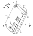
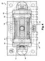
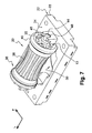
- the device 20 comprises a lower casing 22 with a general substantially rectangular parallelepipedic shape whose upper face 24 is open upwards, and a top cover 26 for enclosing the lower casing that houses the main components of the device 20.
- These components comprise, from bottom to top and in the bottom of the casing 22, two contact springs, left R2 and right R3, where necessary two front and rear contact springs R1 depending on the configurations adopted that will be explained in detail hereinafter, and a central fixed contact ball 28, and a mobile contact element 10 belonging to a rotary signal generator in association with two fixed contact pads P4 and P5.
- a guide and sealing piece 34 common to the contact springs Ri a central trigger member 30 in the general shape of a trigger star with four branches Bi, a single manual control member 32 in the form of a drum 36 with longitudinal and horizontal rotation axis X-X, with its two end O-rings, left 45 and right 47.
- the casing 22 further houses, on the right, an anti-rebound and sealing damper element 12 associated with the mobile contact element 10, and, on the left, an elastic element 14 forming a pawl for producing mechanical pulses or "clicks" in cooperation with an associated toothed wheel of the ratchet type 13 supported by the drum 36.
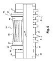
- the single manual control member 32 essentially consists of a rotary operating drum 36 whose central section 38 is of reduced diameter and with a dished concave profile, relative to its two longitudinal end sections, left 40 and right 42, which here have a convex profile each in the form of a radial rib projecting radially outwards relative to the adjacent track 41, 43.
- Diabolo This shape called "Diabolo” (Registered trade mark) is not mandatory.
- use may be made of a generally cylindrical drum with rectilinear external generatrix and making use of distinct surface states for the various sections, for example by means of materials offering different sensations to the touch.
- the outer profile of the central part of the drum may also be convex, non-rectilinear.
- the sections 40 and 42 here are smooth, that is to say with no longitudinal ribs.
- the drum 36 is designed to be rotated by its thinner central part 38 which comprises for this purpose longitudinal ribs 39 which are distributed angularly in a regular manner and separated by as many grooves 49 (in particular see figures 16, 32 and 33).
- Dispensing with the ribs makes it possible to more easily resolve the problems of sealing in relation to the outside at the clearance existing between the drum and the opening 54 provided in the cover 26 for the drum to pass.
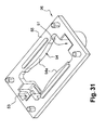
- the dished form of the central section 38 and the presence of the ribs 39 tends to cause contaminants and dust to be dragged inside the casing when the drum is rotated since, as can be seen in particular in Figures 16, 30 and 31, the peaks of the drum ribs very closely espouse the adjacent ribs 54a with a profile that complements the opening 54 of the cover 26.
- the central body of the member 32 is extended, beyond the lateral faces 35, 37 of the longitudinal end of the drum 36, by two longitudinal end sections, left 44 and right 46, constituting a shaft for the rotatable mounting and the guidance in the vertical plane of the member 32 in the lower casing 22 which for this purpose comprises two semi-cylindrical longitudinal housings open vertically upwards, left 48 and right 50, each of which receiving in rotation and vertically sliding the corresponding section 44, 46 respectively.
- Each housing 48, 50 is supplemented by an opposite housing, blind in the upwards direction, formed in the lower face 55 of the cover 26.
- the housing 48 receives the free end section 44 and it is extended inwards via a larger diameter section 48a which receives the left O-ring 45 with an opposite complementary section 51 a in the cover.
- the housing 50 receives the smaller diameter portion of the stepped free end section 46 and it is extended inwards via a large diameter section which receives with clearance the toothed gearwheel 100 and via a section 50a which receives the right O-ring 47 with an opposite complementary section 53a in the cover 26.
- the O-rings 45 and 47 have the function of providing an anti-impact noise damping effect during the manipulations of the member 32 and particularly when it is actuated in the directions F1, F2 and F3.
- the control device or browser 20 here is a device with five switching channels each of which may be used independently of the others by applying a corresponding force Fi to the member 32.
- the first switching channel is a "SELECT" channel which is used by applying a vertical force F1 on the central section 38 of the drum 36 which is used for example to select or confirm a determined position reached by a cursor on a screen of an electronic apparatus (not shown) fitted with the browser 32, each application of a vertical force F1 being used to produce a selection signal or pulse ( Figure 25).
- the second switching channel is for example a channel for "LEFT" movement towards the left of the screen that is used by applying a vertical force F2 on the left section 40 of the drum 36, each application of a vertical force F2 being used to produce a "LEFT” movement signal or pulse ( Figure 24).
- the third switching channel is for example a channel for "RIGHT” movement towards the right of the screen which is used by applying a vertical force F3 on the right section 42 of the drum 36, each application of a vertical force F3 being used to produce a "RIGHT” movement signal or pulse ( Figure 23).
- the circuits of the controlled electronic apparatus may provide that, if the user holds the drum down in the F2 or F3 direction, the pulses are repeated in continuous streams of identical pulses (scrolling), in the same manner as for a computer keyboard when the key is held down.
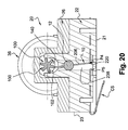
- the fourth switching channel is, for example a channel for "DOWN" movement towards the bottom of the screen which is used by applying to the central part 38 of the drum 36 a circular force F4 tending to make it rotate in a first direction to generate a series of control signals or pulses by means of a signal generator 52 which will be described hereinafter ( Figure 20).
- the fifth switching channel is for example a channel for "UP" movement towards the top of the screen which is used by applying to the drum 36 a circular force F5 tending to make it rotate in a second direction to generate a series of control signals or pulses by means of the signal generator.
- the browser 20 has a symmetry of design relative to the vertical and longitudinal mid-plane PLM in which the axis X-X of rotation of the member 32 is situated, and a general symmetry relative to the vertical and transverse mid-plane PTM, with the exception of the means forming the signal generator 52, which here are grouped together in the right part of the casing 22, and the means 14, 13 generating tactile and auditive pulses, situated on the left, and with the exception of the corresponding output contacts.
- the flat horizontal bottom 56 of the casing receives the central metal ball 28 which protrudes vertically above the plane 56.
- the ball 28 interacts with a central common fixed contact pad P0 which is connected, via a conductive track 60, to an output pin or lug C0 which protrudes transversely forwards in the lower part of the front longitudinal face 23 of the casing 22.
- the output pin or lug C0 like all the lugs Ci, extends while being bent substantially at 180° in a hairpin shape in order to comprise a lower free end stem S0 (Si) which extends substantially horizontally rearwards beneath the lower face 21 of the casing 22.
- the lower face 21 comprises a complementary housing 19 inside which each stem Si may penetrate in order to allow the elastic flexing of the stem when the latter is pressed onto a corresponding conductive track of a printed circuit board (not shown) on which the device 20 is mounted.
- the output lugs or pins "Ci" may be “duplicated” in the two front and rear faces 23. This is obtained directly from the contact grid around which the lower part of the casing is overmoulded.
- soldered output lugs are of the "J" type oriented away from the casing, or of the "G” type bent back beneath the lower casing 22.
- the contact grid shown particularly in Figure 1 corresponds to the configurations that do not use a pair of springs R1.
- Each fixed contact spring R2, R3 is a helical flanged spring of vertical axis and it rests, via its bottom end coil 15, 17, on a second P2 and a third P3 fixed conductive pad each of which is connected, via a conductive track 70, 72, to an output pin or lug C2, C3.
- each of the two fixed contact springs, front and rear R1 is a helical flanged spring of vertical axis and rests, via its bottom end coil 25, on a first fixed conductive pad P1.
- the pads P1 here are connected via a common conductive track 78 to a common output pin or lug C1.
- the two springs R1 are then aligned in the transverse mid-plane PTM which corresponds to the plane of Figure 16.
- the common trigger member 30 may, depending on the different configurations, be used to establish selectively a (first) switching channel between the pads P0 and P1 (through the fixed contact springs R1), a (second) switching channel between the pads P0 and P2 (through the fixed contact spring R2) or a third switching channel between the pads P0 and P3 (through the fixed contact spring R3), and this can be done depending on the vertical force F1, F2 or F3 that is applied to the drum 36 by the user.
- the common trigger member 30, here made of metal, combines four trigger members each of which consists of a trigger branch Bi, of generally radial orientation, which extends outwards from a central portion 80 of generally domed shape and whose concavity is oriented vertically upwards.
- the four branches Bi are identical and distributed angularly at 90° so that the member 30 has a symmetry of design about its central vertical axis Y-Y which, in position mounted in the casing, corresponds to the intersection of the planes PLM and PTM.
- the bottom 84 of the central part 80 comprises a housing 82 whose concavity is oriented downwards in order to rest on the ball 28 (see Figure 15) and to allow slight pivoting movements of the member 30 about the centre of the ball 28.
- the member 30 comprises two diametrically opposed longitudinal branches, left B2 and right B3, which are called second trigger branch B2 and third trigger branch B3 and which belong in particular to the second and third switching channels respectively.
- the member 30 also comprises two first transverse trigger branches B1, diametrically opposed, and able where appropriate to belong to the first switching channel.
- These two branches B1 also serve for the positioning of the member 30 in the housing 57 of the lower casing 22.
- Each trigger branch Bi extends slightly upwards and their free ends are substantially coplanar.
- each free end 86, 88 of the branch B2, B3 extends over and at a distance vertically from the coil 16, 18 at the top end of the associated contact spring R2, R3.
- each free end 90 of the branch B1 (front, rear) extends over and at a distance from the top end coil 27 of the associated fixed contact spring R1 (see Figure 16) when such springs R1 are present.
- the drum 32 rests vertically on the upper convex faces of the free ends 86 and 88 of the longitudinal trigger branches B2 and B3.
- the latter are slightly elastically prestressed downwards by a value Fp and they thus provide an elastic return function of the drum 36 to its high rest position illustrated in the figures in which the longitudinal end sections 44 and 46 are pressing upwards against the upper bottoms of the complementary housings 51, 53 formed in the lower face 55 of the cover 26.
- the 0-rings 45 and 47 are slightly elastically compressed and they perform a function of damping impacts and vibrations when each end 44 or 46 returns in the upward direction to the high rest position, and in particular in order to prevent interference noise.
- the O-rings 45 and 47 may be overmoulded around the sections 44 and 46 and/or made by bi-material moulding.
- the noise damping function is very important insofar as, when the user begins to cause a change of state of the member 30 by pressing on the drum, the triggering in the direction of closing one or more contacts (or “collapsing") cannot be stopped and the assembly acquires a very great speed and a great force of maximal impact. The same applies during the release or opening with corresponding upward movements.
- each upper face of a free end 86, 88 slides along the annular cylindrical path or track 41, 43 respectively of the periphery of the drum and that are adjacent to the sections 40 and 42.
- the design of the member 30 and of its branches Bi is such that, when the free ends of two diametrically opposed branches Bi are acted upon by applying a substantially vertical downward force, the branches deform elastically, then they suddenly change position to incline downwards, this sudden change being used to provide a trigger function in order to establish the corresponding switching channel and also providing a tactile and/or auditive "click" sensation of the sudden change of position.
- the user applies the force F1 substantially in the centre 38 of the drum.
- the cylindrical tracks 41 and 43 of the drum 36 then act simultaneously and symmetrically on the two longitudinal branches B2 and B3.
- the first switching channel corresponding to the application of the force F1 is therefore established and detected in this way.
- the "duplication" of the branches B1 and the pads P1 is redundant, insofar as the sudden change of state of the two branches is virtually simultaneous, but this redundancy provides a large degree of security of operation.
- the elastic return of the drum to the rest state thanks to a greatly reduced number of components and by means of the single manual control member 32 in the form of a drum 36, the elastic return of the drum to the rest state, the switching of the "LEFT”, “RIGHT” or “SELECT” channels in distinctive manner by acting on the distinct zones of the drum, and the tactile and/or auditive effect ("forth” and “back") for each of these three channels are obtained.
- the casing or body of the device comprises no mobile or articulated pieces, thus making it extremely easy to use in the items of equipment that receive this type of device.
- the design of the trigger member 30 and of its branches Bi is such that, when the free ends of the two diametrically opposed branches Bi are acted upon by applying a substantially vertical downward force in the marking in which the member 30 is placed, the branches deform elastically until they reach a deformation with a value tc (called a sudden change of state or "collapsing"), then they suddenly change position to incline downwards.
- This sudden change or collapsing of the member 30 is used to perform a trigger function in order to establish the switching channel corresponding to the angular position of the relative marking V', L', T' relative to the fixed marking V, L, T and also provides a tactile and/or auditive "click" sensation of the sudden change of position.
- the axis X-X of the drum therefore undergoes a rotation through angle ⁇ in the clockwise direction (relative to the plane of Figure 24, for example) about a transverse horizontal axis (orthogonal to the PLM plane) passing substantially through the point of contact 46 of the upper face of the smaller diameter right end cylindrical section 46 of the shaft with the upper bottom of the housing 53 of the cover 26.
- the relative marking V', L', T' also pivots through the same angle ⁇ about its axis T' relative to the fixed marking V, L, T.
- the trigger member 30 follows in rotation the movement of the relative marking V', L', T' thanks to a slight rolling of the concave housing 82 in its central portion 80 on the top of the ball 28.
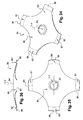
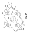
- the fact that a ball 28 is present between the pad P0 and the central portion 80 of the trigger member 30 is used to cause the rolling of a "standard" dome trigger member which usually comprises a flat-bottomed or hemispherically-bottomed central portion (called a "dimple”) projecting upwards, as shown in Figures 34 to 36.
- the drum has sustained a translation t' 2 downwards along the axis V' and a slight translation ⁇ ' 2 from left to right in the direction L'.
- the latter translation is absorbed by the clearance described hereinabove and it produces no effect on the trigger member 30.
- the translation t' 2 causes in the relative marking V', L', T', an equivalent vertical lowering t' 2 of the ends of the branches B2 and B3 of the member 30.
- the maximal lowering value t' 2 max is identical for the two ends of the free branches B2 and B3 of the trigger member 30.
- the lowering value t 2 max b2 of the end of the branch B2 is very clearly greater than the lowering value t 2 max b3 of the end of the branch B3.
- the lowering t 2 max b2 is the result of the combination of t' 2 max and the rotation ⁇ directed downwards
- the lowering t 2 max b3 is that of the combination of t' 2 max and the rotation ⁇ directed upwards.
- the length or height of the springs R2 and R3 is such that, in the rest state, the distance dr between their top coils and the free ends of the branches B2 and B3 of the trigger member 30 is less than t 2 max b2 and greater than t 2 max b3 in order to switch the LEFT channel and not switch the "RIGHT" channel when the force F2 is applied to the left end of the drum.
- the user applies the force F1 substantially in the centre 38 of the drum.
- the cylindrical tracks 41 and 43 of the drum 36 then act simultaneously and symmetrically on the ends of the two longitudinal branches B2 and B3.
- This time difference is related to the production tolerances of the pieces and of the pressing position in the central zone 38 of the drum. It is humanly possible to switch the second channel then the third channel consecutively, or vice versa, in such a brief time.
- the first switching channel corresponding to the application of the force F1 is therefore established and detected in this way.
- the design according to the invention also allows another method (not shown) of detecting the establishment of the first switching channel when F1 is applied.
- the two branches B1 which lower simultaneously with the branches B2 and B3 come, via their free ends 90, virtually simultaneously into contact with the top coil 27 of the additional contact springs R1 opposite.
- the lowering of the ends of the branches B1 is substantially equal to that of the ends of the branches B2 and B3, or, as in the example shown in Figure 25, equal to 0.35 mm.
- the pads P1 of the overmoulded fixed contact must be independent of the pads P2 and P3 and be connected to additional outputs C1 and C1' (distinct or the same in order to provide, or not provide, a redundancy used to increase the security of operation of the "SELECT" function).
- This second configuration avoids the use of the software program associated with the first configuration, but it causes an increase in the number of pieces or components (four contact springs instead of two) and in the number of contact outputs on the printed circuit board which receives the device.
- the design according to the invention allows a third configuration corresponding to a control device with a drum and with three switching channels: "SELECT”, "DOWN” and "UP”.
- the spare parts are absolutely identical to those of the first configuration, except for the contact springs R2 and R3 (resting on the pads P2 and P3) which are removed and replaced by the two contact springs R1 of the second configuration (resting on the pads P1).
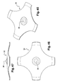
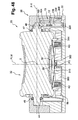
- the design according to the invention allows a fourth configuration represented in Figure 48 in which the ball 28 is removed and replaced by a portion in relief or hemispherical "dimple" 28 which projects vertically downward, that is made from the same die-stamping with the central portion 80 of the trigger member 30, as shown in Figures 45 to 47.
- This die-stamped element or "dimple” ensures, when the drum pivots, a rolling function of the trigger member 30 on the pad P0 of the overmoulded contact grid.
- the origin O' of the relative marking V', L', T' is then the centre of the hemispherical form of the die-stamping 28.
- the pad P0 may be advantageously raised, by stamping/cambering, relative to the plane of the contact grid, and overmoulded in a cylindrically-shaped nipple in order to retain the sealing function of the die-stamped electric contact 28-P0 inside the central recess of the seal 34.
- the latter may have an upward-oriented concave form interacting with the convex form of the downward-oriented die-stamping.
- the design according to the invention allows a fifth configuration, shown in Figure 51, in which the contact springs and the ball 28 are all removed.
- the free ends of the branches B2 and B3 (and where necessary the branches B1) of the trigger member 30 then come directly into contact with the respective pads P2, P3 (and where necessary P1) which can be advantageously raised, by stamping/cambering, relative to the plane of the contact grid, and overmoulded in a cylindrically-shaped nipple in order to retain the sealing function of the electrical contacts inside the elastically deformable cones of the seal 34.
- the drum is stopped, when "LEFT”, “RIGHT” or “SELECT” are pressed, by the free ends of the branches of the member 30 coming directly into contact on the pads Pi of the overmoulded contact grid, the O-rings 45 and 47 serving as dampers to reduce the impact and thus minimize the wear of the contact zones, whose service life (in this configuration which comprises the minimum number of pieces) will be shorter than that of the solution with contact springs.
- the depth of the vertical slots or housings 48 and 50 of the casing is also slightly increased to avoid a hyperstatic phenomenon with the stopping of the branches on the pads.
- the force F1 is approximately 1.5 times greater than the forces F2 and F3. It is remarkable to obtain this ratio, which corresponds to that usually expected by the market, with a single trigger member.
- This result is intrinsic in the design of the invention and it is further enhanced by a "SELECT" stroke that is longer than the "LEFT” and “RIGHT” strokes.
- the tactile sensation is more sensitive to the variations of strokes than to the variations of forces.
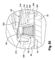
- the contact springs are advantageously of conical form, as shown in Figures 49 and 50, for better vertical stability and to prevent their possible movements in vertical translation in the rest state when the device is subjected to vibrations or impacts in the direction V.
- the signal generator 52 will now be described. Its general design is that described and shown in documents WO-A-02/075641 and WO-A-04/024423 and in the French patent applications No. 0211394 of 13 September 2002, No. 0306475 of 28 May 2003, No. 03.06972 of 11.06.2003 and in the International patent application No. PCT/EP04/051095 of 11.06.2004.
- the generator 52 comprises a straight toothed control gearwheel 100 which is rotatably connected to the central shaft of the drum and which is arranged between the portion of the end section 46 which supports the O-ring 47 and its smaller diameter free end portion.
- an upper section 104 of the mobile contact element 10 in the rest position is received in order to cause the mobile contact element 10 to tilt in one direction or the other (F4, F5) when the gearwheel 100 is rotated by the drum 36 to establish an electric contact between a lower section 220 of the mobile contact element 10 and one or other of the two fixed contact pads P4, P5 and thus generate a control signal, then cause the upper section 104 to escape automatically out of the space 140 delimited by the two consecutive teeth, beyond a determined angle of rotation of the gearwheel.
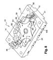
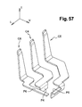
- the mobile contact element 10 is an element made of stamped metal sheet all of whose stems, when at rest, extend in the plane of the metal sheet, here in the vertical longitudinal mid-plane PLM.
- the mobile contact element 10 consists essentially of three adjacent stems of generally vertical orientation, that is to say from left to right when considering Figure 28, a main control and contact stem 200, an intermediate elastic return stem 202, and a free end stem 204 for attachment and installation.
- the design of the mobile contact element 10 is such that the main stem 200 is mounted generally tilting about a horizontal tilting axis Z-Z which is parallel with the axis X-X.
- the main stem 200 is in the form of a band of metal sheet of substantially constant width which comprises, above the tilting axis Z-Z, an upper section 104 and, below the axis, a lower section 206.
- the two sections, upper 104 and lower 206 are vertically aligned under the toothed gearwheel 100 so that the free end of the upper section 104 is received between the consecutive teeth 102 of the gearwheel 100.
- the main stem 200 comprises a horizontal articulation branch 208 which extends horizontally towards the left opposite the intermediate stem 202 (in the vertical plane PLM) and which is intended to be received in the bottom 210 of a V-shaped slot 212 open vertically upwards and formed in the lower part of the casing 22.
- the upper section 104 of the main stem 200 comprises a greater width so as to be more rigid.
- the intermediate stem 202 comprises a first vertical section 214 which extends over the whole height of the element 10 and whose lower end 216 is connected to the lower end 218 of the lower section 206 of the main stem 200, via a lower elbow 220 in a 180° arc.
- the intermediate stem 202 comprises a second vertical section 222 whose upper end 224 is connected to the upper end 226 of the first section 214, via an upper elbow 228 in a 180° arc.
- the lower end 230 of the second section 222 is situated above the tilting axis Z-Z.
- the intermediate stem 202 is extended by the free end stem 204 which comprises a broadened intermediate part 232.
- the free end stem 204 comprises a transverse branch inclined and dished relative to the general vertical plane of the element 10 which constitutes a foot 236 resting on a conductive pad P6 connected to an output C6.
- the sections 206 and 214, with the lower elbow 220 which connects them, are housed in a vertical housing 238 of the lower casing 22 which is delimited by two opposing vertical walls 240 and into the lower part of which the pads P4 and P5 project.
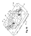
- the anti-rebound damping element 12 is split in a vertical plane at its two opposite axial ends by two slots 250 in which are received corresponding portions of the first vertical section 214 and of the second section 222, on the axis Z-Z, and the longitudinal end sections of the damper 12 are received without clearance in complementary housings of the casing 22.
- the sealing and damping block 12 is arranged substantially on the tilting axis of the mobile contact element 10, that is to say in a zone of the latter that is subject to the least substantial movements in the horizontal plane.
- the width in the transverse direction of the housing 246 is sufficient to allow angular deflections of the portions of the elements 10 that it receives.
- the free end stem 204, 232 which extends beneath the tilting axis Z-Z is inserted vertically into a slot 248, for mounting and attachment, with its lower inclined foot or branch 236 which rests on and is in permanent electric contact with the contact pad P6 arranged in the bottom.
- the enlarged intermediate part 232 is forcibly inserted and it comprises forked ties or spurs 233 which immobilize the element 10 vertically.
- the section 204, and therefore the mobile contact element 10 are thus permanently connected to the pad P6.
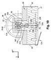
- the free end stem 204, 232 also provides the installation and attachment of the element 10 in the casing 22 so that, by interacting with the horizontal branch 208, it allows a tilting of the main stem 200 in the directions about the axis Z-Z, while performing an elastic return function for the stem 200 in the vertical plane with the upper free end of the upper section 104 between two teeth when at rest as illustrated for example in Figure 19.
- the elastic return function is performed by the intermediate return stem 202.
- the S shape of the mobile contact element 10 provides sufficient elasticity in a very small space, particularly in the longitudinal direction of the device.
- the compactness of such an S-shaped contact element 10 is used to minimize the space requirement of the browser, to make it easier to seal against dust, and also make it easier to produce by stamping in long production runs without smoothness problems, which is a crucial factor to ensure that the shape of the signals produced by the generator is even and symmetrical in "UP” and in "DOWN".
- the damper block 12 obstructs in sealing manner the upper entrance of the housing 238 in which the pads P4 and P5 are housed, while thus preventing any ingress of dust harmful to the electric contacts coming from outside the device, or wear by friction between the various pieces and components moving inside the device 20.
- the block 12 retards the return speed of the mobile contact element 10 towards its vertical balanced position, after it has undergone an angular deviation by electric deformation during each passage of a tooth 102 of the control gearwheel 100 of the control member 32.
- the damping effect provided by the block 12 prevents the risk of violent oscillation(s) of the element 10 about its balanced position, between two consecutive passes or clearances of teeth 102 which could cause interference rebounds on the contact pad opposite the one on which the lower elbow 220 establishes a string of electric pulses corresponding to the direction of rotation of the drum 36.
- damper block 12 helps to simplify the software for analysing the signals by providing no function for distinguishing the interference signals resulting from the rebounds.
- the piece 34 is a piece moulded in flexible material, for example natural or synthetic elastomer material.
- It comprises a lower horizontal bedplate 300 whose partially recessed lower face 302 rests in sealing manner against the bottom 56 of the lower casing 22.
- the lower bedplate 300 has a rectangular contour and is of symmetrical design relative to its two vertical longitudinal and transverse mid-planes.
- the bedplate 300 comprises a heel 306 which extends vertically upwards beyond the upper horizontal face 308 of the bedplate 300 and which constitutes a block for abutment and impact damping for the ends 40 and 42 of the drum 36 when the latter is caused to tilt by applying a force F1, F2 or F3.
- the bedplate 300 comprises an upper tubular extension 310 whose internal vertical drilling 312 is emergent at its two ends and receives the metal ball 28 which it positions at right angles and above the central contact pad P0.
- the positioning of the piece 34 is provided by the shapes of the bedplate 300 which is received in complementary hollow forms of the lower housing 57 formed in the bottom of the casing 22.
- Each contact spring Ri is received in a frustoconical tubular extension 314 opening at its two ends which is made, like the extension 310, of the same material and in one piece by moulding with the bedplate 300.
- the piece 34 comprises four tubular extensions 314 distributed in pairs in the vertical, longitudinal and transverse mid-planes of the piece 34, and symmetrically either side of the central tubular extension 310 which receives the ball 28.
- each tubular extension 314 comprises a frustoconical intermediate section 316 which extends above the upper face 308 of the bedplate 300 and a cylindrical tubular upper free end section 318.
- section 318 The dimensions and the design of the section 318 are such that its free end upper annular edge 320 receives resting on it the free end section of the corresponding branch Bi (that is to say the branch B2 when considering Figure 50), this free end section 86 interacting in sealed manner with the edge 320 to close off the cavity 315 internal to the tubular extension 314 which houses the contact spring R2.
- the internal housing 315 is closed off in sealed manner at its two ends.
- the total height of the housing 315 is naturally greater than the total height of the spring Ri that it receives so that, when at rest - that is to say in the absence of deformation action on the common member 30 - there is no electric contact between the branch Bi and the associated pad Pi.
- the piece 34 performs an individual sealing function for each contact assembly formed by a branch Bi and by a pad Pi with a spring Ri.
- the flexibility of the elastomer material of which the piece 34 is made allows it to fully espouse by its lower face 302 the horizontal face forming the inner bottom 56 of the casing 22 and, locally by the upper annular face of each of its tubular extensions, the generally hemispherically-shaped surface of the corresponding portion of the common trigger member 30.
- the flexibility of the elastomer material and the frustoconical shape of the tubular extensions 314 are determined so as "to follow" the rotary movements and the elastic deformations of the trigger member 30, without detracting from the seal and without generating high reaction forces which oppose the sudden change of state of the trigger member 30.
- the lower face 302 comprises a recess or a peripheral facing 303 which interconnects the housings 315 of the four tubular extensions 314 in order to form, in the assembled position, an "air chamber” sealed from dust.
- the piece 34 also performs a function of damping the vibrations and hence the noises produced by the sudden changes of state of the common trigger member 30.
- the O-rings 45 and 47 have the sole purpose of reducing the noises produced during the downward pressings (and the upward releases) when a force F1, F2 or F3 is applied, by damping the impacts of the sections 44 and 46, on the one hand, on the bottom of the vertical slots 48 and 50 of the casing and, on the other hand, on the upper bottom of the housings 51 and 53 of the cover 26.
- the dimensions of the O-rings and those of the casing housings in which they slide are such that, at the end of a pressing or release, the corresponding O-ring first comes to slightly collapse on the bottom of its housing before the corresponding longitudinal end section 44, 46 of the control member 32 finally stops against the bottom of the corresponding housing in the casing or the cover.
- the cavity of the casing comprises, opposite each of the two end sections 40 and 42 of the drum 36, a cradle 252, 254 of cylindrical shape which forms a safety stop against the lowering of the drum.
- these cradles 252 and 254 are determined so that such a stop occurs only after the longitudinal end section 44 of the control member 30 and/or the vertical slot 50 of the casing has undergone a slight elastic deformation, and naturally before the limit of this elastic deformation is reached.
- the cradles 252 and 254 are furnished with a slot in their central part which receives the extension in the shape of the damper pad 306 of the piece 34.
- the pads 306 thus play the role of retarders and transitory dampers between the pressing of the longitudinal end sections of the control member 30 on the bottom of the vertical slots 48 and 50 of the casing, and the eventual safety stop of the sections 40 and 42 on their respective cradles 252 and 254.
- This safety stop also allows the device to withstand without damage the drop tests which are carried out on equipment or apparatus receiving this type of device and which involve causing drops of approximately 1.5 m onto a concrete slab in turn on all the faces of the apparatus, including that in which the device is placed.
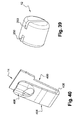
- the device 20 comprises the elastic pawl 14 made of bent metal sheet and stamped and illustrated in detail in Figure 40, which interacts with the associated ratchet-type toothed wheel 13 supported by the drum 36 and illustrated in detail in Figures 7, 22 and 33.
- the pawl 14 comprises a vertical branch 400 for installation and attachment in a complementary slot 402 of the casing, and a substantially vertical active branch 404 to which it is connected by a lower elbow 406 which gives the branch 404 its elastic deformation capabilities.
- the upper free end section 408 of the active branch 404 of the pawl 14 has a convex domed profile oriented towards the wheel 13.
- the wheel 13 here is made for example of the same material and in one piece by moulding in the left longitudinal end transverse face of the drum 36 and it comprises a series of housings 410, each of generally axial orientation, and which are separated from one another by shaped radial partitions 412.
- the housings 410 and the partitions 412 are equal in number to the number of teeth of the control gearwheel 100.
- the ratchet wheel 13 is integral in rotation with the gearwheel 100 and, in each angular rest position of the control member 32, the boss 408 of the pawl 14 is received fitted elastically into a housing 410 of the wheel 13, while the section 104 of the mobile contact element 10 is received with clearance between two consecutive teeth 102 of the gearwheel 100.
- the pawl 14 with the wheel 13 thus performs a first angular rest positioning function of the drum 32.
- the user thus perceives a tactile sensation of clearance and therefore of generation of a corresponding signal, and an auditive sensation when the boss 408, under the action of the elastic active branch 404, re-enters a housing 410.
- the finger or boss 18 of the pawl 14 thus procures a sudden detent effect when it interacts successively with the housings 410 and the partitions 412 of the wheel 13.
- Each housing 410 is advantageously delimited by two opposing inclined lateral faces in order to form a V opening radially outwards, the inclination being of the order of 5° to 8°.
- the V profile of the housing 410 in which the boss 408 is received supplies a return spring effect acting on the drum vertically and upwards to compensate for the friction forces of the pawl on the drum which pose no problem during the vertically downward pressing by the user's finger but which could compromise correct operation during the release because the sole upward return force is then that exerted by the member 30 (when the user's finger has relaxed the application of the downward force).
- This elastic return effect is added to that exerted by the branches of the trigger member 30.
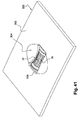
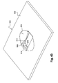
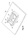
- Figures 41 to 44 illustrate how the device according to the invention is elastically fitted into a portion of a wall or partition 500 in the shape of a plate belonging to an item of electronic apparatus or equipment furnished with the device 20 according to the invention that has just been described.
- the plate 500 comprises, on its upper face 502, a central hollow recess 504 in the shape of a concave bowl which guides the user's finger towards the control member 32 which is received in a vertical housing with rectangular contour 506 formed in the plate 500 and which opens out.
- the plate 500 also comprises two vertical partitions 512 between the inner faces 514 of which the transverse and opposite faces of the casing 22 are received and which each comprise, at their free lower ends, two hooks 516 each of which is intended to be received in a complementary notch 518 formed opposite in a corner of the lower face 21 of the casing 22.
- each hook 516 is formed as a ramp 520 in order to cause an elastic deformation of the partition 514 and an elastic socket or "clip" attachment of the device 20 beneath the lower face 508 between the ribs 510 and the partitions 512 with elastic fitting of each hook 516 in a housing 518.
- the respective dimensions of the plate 500 and of the device 20 are such that the drum 36 is slightly flush with the centre of the bowl 504, but makes practically no projection beyond the plane of the upper face 502.
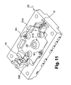
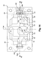
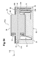
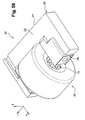
- the device 20 uses an S-shaped mobile contact element 10 according to the teachings of the invention.
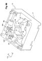
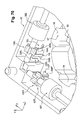
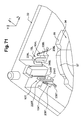
- a damping and sealing block 12 (see Figure 60) is again used here to effectively protect the fixed contacts P4 and P5 against dust.
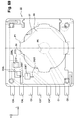
- Figure 56 is an end view along the arrow F56 of Figure 52 which illustrates the lower casing 22 "empty", that is to say without the components that it contains that comprise the drum 32 with its gearwheel 100, the mobile contact element 10, the pawl 14 and of course the flat cover 26.
- a major portion of the drum 32, 36 protrudes transversely beyond one of the two lateral and vertical faces 23 of the casing 22.
- the drum 32 is no longer a cylindrical drum with rectilinear generatrix and grooved as in Figures 52 to 57, but a large diameter wheel which greatly protrudes transversely either side of the casing 22, that is to say beyond each of the two longitudinal and vertical lateral faces 23.
- the wheel or drum 32 may where necessary be made by bi-material moulding according to the technique used for example for computer control mouse balls, with a central hub made of hard thermoplastic and an injected radially external enveloping crown in an elastomer procuring a "soft touch”.
- This configuration is particularly valuable when fixed or mobile members of the item of electronic apparatus or equipment that receives a control device 20 must be placed extremely close to the drum or wheel 32 in spaces or volumes delimited, on the one hand, by the casing 22 and, on the other hand, by two opposing shells (not shown) of the casings of the item of electronic apparatus or equipment.
- the casing 22 with its elastic output connection lugs Ci is pressed against one face of a printed circuit board or card which comprises an opening or window for the passage of the corresponding part of the drum wheel 35 with the aid of a support (not shown) resting on the other lateral face 23 of the casing 22.
- Such a support also comprises a cut-away for the passage of the wheel and the swellings forming hub-carriers in the faces 23, such a cut-away also providing the guidance and positional retention of the device 20 in the item of equipment.
- the two signal generators 52L, 52T are produced by using a mobile contact element 10L, 10T according to the teachings of the invention, both by its design illustrated in detail in Figures 27 to 29 and by its arrangement in the lower casing 22 with its damping and sealing means which may, for each element 10L, 10T, consist of a damping and sealing block like the previously described block 12, but which is not shown in the figures.
- This grid consists of conductive elements around which the lower casing 22 of the "Trackball" 20 is overmoulded.
- the housing 57 formed in the central part of the casing 22 delimited by the horizontal bottom 56 is formed so as to receive the common trigger element 30 with four branches each end of which is received in a complementary portion 59 of the housing 57, in the same way as the transverse branches B1 of the member 30 previously described with reference to the devices controlled by a roller-drum 30, 36.
- the lower part of the ball 600 acts on the central part of the common trigger member 30 so that this central part comes into electric contact with the central contact pad P0, while the free ends of the radial branches of the member 30 are pressing against and in permanent electric contact each with a portion of a common pad P1.
- the "Trackball" type device shown in Figures 65 to 72 comprises a piece 34 moulded in flexible material, for example in elastomer, which is received in the housing 57 and which caps the common trigger member 30 with its electric contact zones.
- the element 34 has the general form of an annular sealing crown whose external contour complements that of the housing 57, 59 with which it is in lateral sealed contact.
- the lower annular edge 602 of the piece 34 rests in sealed manner on an annular peripheral zone opposite the upper face of the common trigger member 30 which is a zone subject to very slight movements when the trigger member 30 "collapses" under the action of the ball 600, thus providing a complete seal at all times.
Landscapes
- Physics & Mathematics (AREA)
- General Physics & Mathematics (AREA)
- Engineering & Computer Science (AREA)
- Automation & Control Theory (AREA)
- Position Input By Displaying (AREA)
- Mechanisms For Operating Contacts (AREA)
- Adjustable Resistors (AREA)
Applications Claiming Priority (1)
| Application Number | Priority Date | Filing Date | Title |
|---|---|---|---|
| FR0409247A FR2874739B1 (fr) | 2004-09-01 | 2004-09-01 | Dispositif perfectionne de commande a tambour et a voies de commutation multiples |
Publications (1)
| Publication Number | Publication Date |
|---|---|
| EP1632968A1 true EP1632968A1 (de) | 2006-03-08 |
Family
ID=34948787
Family Applications (1)
| Application Number | Title | Priority Date | Filing Date |
|---|---|---|---|
| EP05107825A Withdrawn EP1632968A1 (de) | 2004-09-01 | 2005-08-26 | Verbesserte Steuereinrichtung mit einer Trommel und mit mehreren Schaltungskanalen |
Country Status (3)
| Country | Link |
|---|---|
| US (1) | US20060071489A1 (de) |
| EP (1) | EP1632968A1 (de) |
| FR (1) | FR2874739B1 (de) |
Cited By (1)
| Publication number | Priority date | Publication date | Assignee | Title |
|---|---|---|---|---|
| EP2755218A1 (de) * | 2013-01-14 | 2014-07-16 | Alps Electric Co., Ltd. | Schaltvorrichtung mit kombinierter Betätigung |
Families Citing this family (7)
| Publication number | Priority date | Publication date | Assignee | Title |
|---|---|---|---|---|
| US20080174572A1 (en) * | 2007-01-19 | 2008-07-24 | Kabushiki Kaisha Tokai Rika Denki Seisakusho | Input apparatus |
| DE102008012921B4 (de) * | 2008-03-06 | 2018-08-09 | Leopold Kostal Gmbh & Co. Kg | Druck- und drehbetätigbares Bedienelement für ein Kraftfahrzeug |
| US8101876B2 (en) * | 2008-04-22 | 2012-01-24 | Sonion Aps | Electro-mechanical pulse generator |
| US20120205868A1 (en) * | 2011-02-15 | 2012-08-16 | Monica Yahoodazadeh | Sudoku gaming board |
| DE102012012172A1 (de) * | 2012-06-19 | 2013-12-19 | Leopold Kostal Gmbh & Co. Kg | Druck- und drehbetätigbares Bedienelement für ein Kraftfahrzeug |
| DE102017210254A1 (de) * | 2017-06-20 | 2018-12-20 | Zf Friedrichshafen Ag | Bedieneinrichtung für ein Lenkrad eines Fahrzeugs |
| DE102023135596A1 (de) | 2023-12-18 | 2025-06-18 | Valeo Schalter Und Sensoren Gmbh | Bedienvorrichtung für ein Kraftfahrzeug mit drückbarem Bedienrad und Haptik-Aktuator, Kraftfahrzeug und Verfahren zum Betätigen einer Bedienvorrichtung |
Citations (4)
| Publication number | Priority date | Publication date | Assignee | Title |
|---|---|---|---|---|
| US5422448A (en) * | 1992-11-17 | 1995-06-06 | Smk Corp. | Contact piece for use in a rotary encoder and method of constructing same |
| EP1073080A2 (de) * | 1999-07-27 | 2001-01-31 | Alps Electric Co., Ltd. | Mehrrichtungseingabeeinrichtung |
| WO2002075641A1 (en) * | 2001-03-16 | 2002-09-26 | Itt Manufacturing Enterprises Inc. | Trackball for controlling cursor movement on a screen |
| WO2004024423A2 (en) * | 2002-09-13 | 2004-03-25 | Itt Manufacturing Enterprises, Inc. | Trackball device for controlling an electronic apparatus, and production process |
Family Cites Families (13)
| Publication number | Priority date | Publication date | Assignee | Title |
|---|---|---|---|---|
| JP2557557Y2 (ja) * | 1991-02-12 | 1997-12-10 | ミネベア株式会社 | キースイッチ |
| US5530455A (en) * | 1994-08-10 | 1996-06-25 | Mouse Systems Corporation | Roller mouse for implementing scrolling in windows applications |
| JP3437054B2 (ja) * | 1997-05-12 | 2003-08-18 | アルプス電気株式会社 | 多入力スイッチ |
| JP3694392B2 (ja) * | 1997-08-22 | 2005-09-14 | アルプス電気株式会社 | 複合操作型電気部品 |
| JP3951485B2 (ja) * | 1998-12-25 | 2007-08-01 | 松下電器産業株式会社 | 回転・押圧操作型電子部品およびそれを用いた電子機器 |
| JP3952642B2 (ja) * | 1999-09-20 | 2007-08-01 | 松下電器産業株式会社 | 押圧・回転操作型電子部品 |
| EP1444712A2 (de) * | 2001-11-12 | 2004-08-11 | Methode Electronics, Inc. | Elektromechanischer impulsgenerator mit einem zahnkranzartigen drehbaren nockenrad |
| JP2003228459A (ja) * | 2001-11-30 | 2003-08-15 | Fujitsu Component Ltd | 入力装置 |
| US6717572B1 (en) * | 2002-03-14 | 2004-04-06 | Shin Jiuh Corp. | Modular rolling axis apparatus |
| US6809275B1 (en) * | 2002-05-13 | 2004-10-26 | Synaptics, Inc. | Rotary and push type input device |
| US6987505B1 (en) * | 2002-06-03 | 2006-01-17 | Microsoft Corporation | Modular scroll wheel with integral detent-engaging spring tab |
| DE20211487U1 (de) * | 2002-07-12 | 2002-10-17 | Methode Electronics Inc | Elektromechanischer Impulsgenerator mit einem manuell betätigbaren Eingaberad in einem Kraftfahrzeug |
| FR2856191B1 (fr) * | 2003-06-11 | 2005-07-22 | Itt Mfg Enterprises Inc | Dispositif de commande a tambour et a voies de commutation multiples, et appareil electronique equipe de tels dispositifs |
-
2004
- 2004-09-01 FR FR0409247A patent/FR2874739B1/fr not_active Expired - Fee Related
-
2005
- 2005-08-26 EP EP05107825A patent/EP1632968A1/de not_active Withdrawn
- 2005-08-26 US US11/213,578 patent/US20060071489A1/en not_active Abandoned
Patent Citations (4)
| Publication number | Priority date | Publication date | Assignee | Title |
|---|---|---|---|---|
| US5422448A (en) * | 1992-11-17 | 1995-06-06 | Smk Corp. | Contact piece for use in a rotary encoder and method of constructing same |
| EP1073080A2 (de) * | 1999-07-27 | 2001-01-31 | Alps Electric Co., Ltd. | Mehrrichtungseingabeeinrichtung |
| WO2002075641A1 (en) * | 2001-03-16 | 2002-09-26 | Itt Manufacturing Enterprises Inc. | Trackball for controlling cursor movement on a screen |
| WO2004024423A2 (en) * | 2002-09-13 | 2004-03-25 | Itt Manufacturing Enterprises, Inc. | Trackball device for controlling an electronic apparatus, and production process |
Cited By (1)
| Publication number | Priority date | Publication date | Assignee | Title |
|---|---|---|---|---|
| EP2755218A1 (de) * | 2013-01-14 | 2014-07-16 | Alps Electric Co., Ltd. | Schaltvorrichtung mit kombinierter Betätigung |
Also Published As
| Publication number | Publication date |
|---|---|
| FR2874739A1 (fr) | 2006-03-03 |
| FR2874739B1 (fr) | 2006-10-20 |
| US20060071489A1 (en) | 2006-04-06 |
Similar Documents
| Publication | Publication Date | Title |
|---|---|---|
| EP1111636B1 (de) | Schalter | |
| KR101361741B1 (ko) | 스위치 | |
| EP1695529B1 (de) | Rotator-rad | |
| US6717572B1 (en) | Modular rolling axis apparatus | |
| US6831238B1 (en) | Finger-controllable multi-directional switch | |
| KR20040014296A (ko) | 휴대용 전자기기 | |
| EP1632968A1 (de) | Verbesserte Steuereinrichtung mit einer Trommel und mit mehreren Schaltungskanalen | |
| US8115120B2 (en) | Electrical switch with multiple switching channels | |
| AU2018405470B2 (en) | Key switch mechanisms, user input devices and methods of fabricating a key switch mechanism | |
| EP1631976B1 (de) | Steuereinrichtung des trommeltyps mit mehreren schaltwegen und mit solchen einrichtungen ausgestattetes elektronisches gerät | |
| TWI687845B (zh) | 鍵盤裝置及其按鍵結構 | |
| JP2004220536A (ja) | 情報処理装置の入力装置 | |
| US9141203B2 (en) | Key free mouse device | |
| JP4050067B2 (ja) | 複合スイッチ構造体 | |
| TWI399075B (zh) | 按鍵裝置及裝設有該按鍵裝置之攜帶型電子裝置 | |
| KR100651523B1 (ko) | 단말기의 방향키 장치 | |
| JP4179909B2 (ja) | ポインティングデバイス | |
| CN103677327A (zh) | 开关触发装置 | |
| WO2005041234A1 (en) | Electrical switch having multiple scanning and selecting ways and a single actuator | |
| US20060221053A1 (en) | Drum control device for an electronic apparatus | |
| JP2007507058A (ja) | スイッチドーム素子 | |
| JP2008277034A (ja) | スイッチ機構およびスイッチ機構を有する電子機器 | |
| JP2003233457A (ja) | ポインティングデバイス | |
| KR20120077048A (ko) | 터치 폰 | |
| KR20030044089A (ko) | 이중 홈 구조를 가지는 키패드 어셈블리의 실리콘 패드 |
Legal Events
| Date | Code | Title | Description |
|---|---|---|---|
| PUAI | Public reference made under article 153(3) epc to a published international application that has entered the european phase |
Free format text: ORIGINAL CODE: 0009012 |
|
| AK | Designated contracting states |
Kind code of ref document: A1 Designated state(s): AT BE BG CH CY CZ DE DK EE ES FI FR GB GR HU IE IS IT LI LT LU LV MC NL PL PT RO SE SI SK TR |
|
| AX | Request for extension of the european patent |
Extension state: AL BA HR MK YU |
|
| 17P | Request for examination filed |
Effective date: 20060602 |
|
| AKX | Designation fees paid |
Designated state(s): AT BE BG CH CY CZ DE DK EE ES FI FR GB GR HU IE IS IT LI LT LU LV MC NL PL PT RO SE SI SK TR |
|
| GRAP | Despatch of communication of intention to grant a patent |
Free format text: ORIGINAL CODE: EPIDOSNIGR1 |
|
| STAA | Information on the status of an ep patent application or granted ep patent |
Free format text: STATUS: THE APPLICATION IS DEEMED TO BE WITHDRAWN |
|
| 18D | Application deemed to be withdrawn |
Effective date: 20071005 |