EP1631736B1 - Abgasturbine für einen abgasturbolader - Google Patents
Abgasturbine für einen abgasturbolader Download PDFInfo
- Publication number
- EP1631736B1 EP1631736B1 EP04729870.8A EP04729870A EP1631736B1 EP 1631736 B1 EP1631736 B1 EP 1631736B1 EP 04729870 A EP04729870 A EP 04729870A EP 1631736 B1 EP1631736 B1 EP 1631736B1
- Authority
- EP
- European Patent Office
- Prior art keywords
- exhaust gas
- gas turbine
- spiral housing
- distributor
- housing
- Prior art date
- Legal status (The legal status is an assumption and is not a legal conclusion. Google has not performed a legal analysis and makes no representation as to the accuracy of the status listed.)
- Expired - Lifetime
Links
- 238000007789 sealing Methods 0.000 claims description 7
- 239000002184 metal Substances 0.000 claims description 6
- 125000006850 spacer group Chemical group 0.000 claims description 5
- 239000011324 bead Substances 0.000 claims description 3
- 230000008646 thermal stress Effects 0.000 description 5
- 238000004519 manufacturing process Methods 0.000 description 3
- 238000009413 insulation Methods 0.000 description 2
- 230000007704 transition Effects 0.000 description 2
- 230000001419 dependent effect Effects 0.000 description 1
- 230000000694 effects Effects 0.000 description 1
- 230000007257 malfunction Effects 0.000 description 1
- 239000000463 material Substances 0.000 description 1
- 230000002028 premature Effects 0.000 description 1
- 230000035882 stress Effects 0.000 description 1
- 210000002105 tongue Anatomy 0.000 description 1
- 238000003466 welding Methods 0.000 description 1
Images
Classifications
-
- F—MECHANICAL ENGINEERING; LIGHTING; HEATING; WEAPONS; BLASTING
- F01—MACHINES OR ENGINES IN GENERAL; ENGINE PLANTS IN GENERAL; STEAM ENGINES
- F01D—NON-POSITIVE DISPLACEMENT MACHINES OR ENGINES, e.g. STEAM TURBINES
- F01D25/00—Component parts, details, or accessories, not provided for in, or of interest apart from, other groups
- F01D25/24—Casings; Casing parts, e.g. diaphragms, casing fastenings
- F01D25/26—Double casings; Measures against temperature strain in casings
-
- F—MECHANICAL ENGINEERING; LIGHTING; HEATING; WEAPONS; BLASTING
- F01—MACHINES OR ENGINES IN GENERAL; ENGINE PLANTS IN GENERAL; STEAM ENGINES
- F01D—NON-POSITIVE DISPLACEMENT MACHINES OR ENGINES, e.g. STEAM TURBINES
- F01D17/00—Regulating or controlling by varying flow
- F01D17/10—Final actuators
- F01D17/12—Final actuators arranged in stator parts
- F01D17/14—Final actuators arranged in stator parts varying effective cross-sectional area of nozzles or guide conduits
- F01D17/16—Final actuators arranged in stator parts varying effective cross-sectional area of nozzles or guide conduits by means of nozzle vanes
- F01D17/165—Final actuators arranged in stator parts varying effective cross-sectional area of nozzles or guide conduits by means of nozzle vanes for radial flow, i.e. the vanes turning around axes which are essentially parallel to the rotor centre line
-
- F—MECHANICAL ENGINEERING; LIGHTING; HEATING; WEAPONS; BLASTING
- F01—MACHINES OR ENGINES IN GENERAL; ENGINE PLANTS IN GENERAL; STEAM ENGINES
- F01D—NON-POSITIVE DISPLACEMENT MACHINES OR ENGINES, e.g. STEAM TURBINES
- F01D25/00—Component parts, details, or accessories, not provided for in, or of interest apart from, other groups
- F01D25/24—Casings; Casing parts, e.g. diaphragms, casing fastenings
-
- F—MECHANICAL ENGINEERING; LIGHTING; HEATING; WEAPONS; BLASTING
- F01—MACHINES OR ENGINES IN GENERAL; ENGINE PLANTS IN GENERAL; STEAM ENGINES
- F01D—NON-POSITIVE DISPLACEMENT MACHINES OR ENGINES, e.g. STEAM TURBINES
- F01D9/00—Stators
- F01D9/02—Nozzles; Nozzle boxes; Stator blades; Guide conduits, e.g. individual nozzles
- F01D9/026—Scrolls for radial machines or engines
-
- F—MECHANICAL ENGINEERING; LIGHTING; HEATING; WEAPONS; BLASTING
- F05—INDEXING SCHEMES RELATING TO ENGINES OR PUMPS IN VARIOUS SUBCLASSES OF CLASSES F01-F04
- F05D—INDEXING SCHEME FOR ASPECTS RELATING TO NON-POSITIVE-DISPLACEMENT MACHINES OR ENGINES, GAS-TURBINES OR JET-PROPULSION PLANTS
- F05D2220/00—Application
- F05D2220/40—Application in turbochargers
-
- F—MECHANICAL ENGINEERING; LIGHTING; HEATING; WEAPONS; BLASTING
- F05—INDEXING SCHEMES RELATING TO ENGINES OR PUMPS IN VARIOUS SUBCLASSES OF CLASSES F01-F04
- F05D—INDEXING SCHEME FOR ASPECTS RELATING TO NON-POSITIVE-DISPLACEMENT MACHINES OR ENGINES, GAS-TURBINES OR JET-PROPULSION PLANTS
- F05D2230/00—Manufacture
- F05D2230/60—Assembly methods
- F05D2230/64—Assembly methods using positioning or alignment devices for aligning or centring, e.g. pins
- F05D2230/642—Assembly methods using positioning or alignment devices for aligning or centring, e.g. pins using maintaining alignment while permitting differential dilatation
Definitions
- the invention relates to an exhaust gas turbine for an exhaust gas turbocharger according to the preamble of claim 1.
- an exhaust gas turbine for an exhaust gas turbocharger in which a spiral housing made of sheet metal is firmly connected on the one hand with a contour sleeve and on the other hand is braced via an intermediate ring by means of a clamping band with a central bearing housing of the turbine.
- the intermediate ring may be integrally formed with the contour sleeve according to a version of the exhaust gas turbine or form a separate component.
- the spiral housing is composed of two sheet metal shells, one of which forms the channel wall of the spiral channel which faces the nozzle, while the other shell forms the channel wall of the spiral channel facing outwards.
- the outwardly facing shell may be surrounded by a further shell with an air gap for thermal insulation.
- the spiral housing is complicated and therefore expensive to manufacture and assemble. Furthermore, it has a considerable weight and in particular allows no compensation of different thermal expansions of the individual housing parts to each other, without significant thermal stresses occur. Such thermal stresses can lead to malfunction and cause premature wear.
- the adjustment mechanism for the vanes, a bearing ring for the vanes, the contour sleeve and the vanes themselves can form a preassembled unit.
- a turbine housing for an exhaust gas turbocharger wherein the volute casing is double-walled.
- the inner wall which forms the spiral channel, adjoins an inlet flange via an inlet funnel, which opens tangentially into the spiral housing.
- the outer wall is welded to the inlet flange, while the inner wall to the outer wall and the inlet flange has a sliding fit, so that thermal expansions in the direction of the inlet funnel between the inner and outer wall generate no thermal stresses. Due to the principle, however, no compensation of the inner and outer walls of the spiral housing in the axial direction of the exhaust gas turbine is provided, so that in particular at high temperature differences between the inner and outer shell due to high voltages, a durability can not be guaranteed.
- the invention is based on the object to design an exhaust gas turbine with a clam shell turbine housing made of sheet metal so that the parts are simple and lightweight and generate the lowest possible voltages under the influence of heat. It is achieved according to the invention by the features of claim 1. Further advantageous embodiments will be apparent from the dependent claims.
- the spiral housing and the outer shell are cup-shaped.
- the outer shell can be made substantially cylindrical, while the spiral housing forms a spiral channel according to the specifications of the desired flow conditions, the flow cross section tapers to a diffuser back.
- the volute casing and the outer shell are delimited at the end face facing the nozzle of parts of the distributor, which comprises a contour sleeve, a bearing ring and an intermediate ring.
- One in cross section V-shaped clamping ring clamps the outer shell via the intermediate ring with a central bearing housing of the exhaust gas turbocharger, while the inner spiral housing connects via at least one axially resilient element to a part of the distributor, for example to the intermediate ring or the bearing ring.
- the spiral housing can expand under the influence of heat in the axial and radial directions, without exerting appreciable stresses on the adjacent parts of the distributor or the outer shell.
- the resilient element can be formed in a simple manner by a corrugated pipe-like part of the spiral housing, which is formed directly on this during the manufacture of the spiral housing and expediently has a smaller wall thickness than the rest of the spiral housing.
- the resilient element consists of a sliding seat which is provided between a part of the distributor and the volute casing.
- the diameter difference between a cylindrical connection and the radial boundary of the spiral channel is bridged by a radially directed, integrally formed transition.
- connection point in addition to the sliding seat by a heat-resistant sealing element, e.g. in the form of a bead, which is formed on the connection of the spiral housing and rests against the shoulder.
- a Contour sleeve and a bearing ring for adjustable vanes covered by Spacer bolts are interconnected and form a flow channel, which adjoins a spiral channel formed by the spiral housing.
- the bearing ring is attached to an intermediate ring which is braced on an outwardly facing outer flange together with a flange of the outer shell by a clamping ring with an adjacent housing part of the exhaust gas turbocharger.
- the bearing ring and the bearing ring and the intermediate ring form the frontal boundary of the spiral channel, so that the number of required components, the cost of materials and weight are very low.
- the radially inner part of the spiral housing is suitably connected via a base plate with the contour sleeve.
- the base plate which may be formed directly on the spiral housing or sealed by a separate seal, serves at the same time for sealing the spiral housing relative to the contour sleeve. This can be done firstly in the axial direction or in the radial direction by a correspondingly acting clamping ring which presses the base plate in the corresponding radial or axial direction against the contour sleeve. In this case, an additional seal can be provided between the base plate and the contour sleeve.
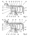
- the exhaust gas turbine 10 includes a contour sleeve 13, which is connected via spacer bolts 14 with a bearing ring 17 for not shown, adjustable guide vanes.
- the spacer bolts 14, of which several are distributed on the circumference, have stops 15, against which the contour sleeve 13 and the bearing ring 17 abut and are held by a rivet head 16 at the end of the spacer bolt 14.
- a flow channel 30 is formed, which leads to a radially inner, not shown impeller and in which the vanes are arranged distributed over the circumference.
- the bearing ring 17 is fixed to an intermediate ring 18 which is connected to an outer conical flange 19 by a cross-sectionally V-shaped clamping ring 24 in a known manner is braced against an unillustrated central bearing housing of the exhaust gas turbine. While in the execution after Fig. 1 the intermediate ring 18 is attached directly to its inner radial flange 20 on the bearing ring 17 is in the execution after Fig.
- the bearing ring 17 is connected via a support plate ring 25 with a flange 38 of the only indicated bearing housing 37 by an inner flange 26 of the support plate ring 25 is fixed to the bearing ring 17, and an outer flange 27 of the support plate ring 25 through the clamping ring 24 with a suitable flange 38 of the Bearing housing 37 is braced.
- the support plate ring 25 is elastically yielding and thus compensates for thermal expansion between the distributor 13, 14, 17 and the housing of the turbocharger.
- the flow channel 30 is surrounded radially on the outside by a spiral channel 12 through which exhaust gas is supplied.
- a spiral channel 12 through which exhaust gas is supplied.
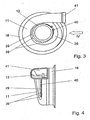
- its flow cross section narrows continuously from a tangentially opening inlet funnel 41 to the flow channel 30, resulting in a spiral shape of the spiral housing 11, which essentially forms the spiral channel 12.
- the cross-sectional constriction of the spiral channel 12 is indicated by a plurality of dashed lines sections of the spiral housing, which form an angle to each other and in the Fig. 1 and 2 were turned into the drawing plane.
- An outer shell 21 surrounds the spiral housing 11 and forms an air gap 22 with it for thermal insulation.
- the outer shell 21 does not need to have a spiral shape. It is suitably designed for manufacturing reasons as a cylindrical pot, the conical flange 23 facing the intermediate ring 18 and with this ( Fig. 1 ) and possibly with the support plate ring 25 ( Fig. 2 ) is clamped together by the clamping ring 24.
- the spiral housing 11 also has the shape of a pot with an annular cross-section, wherein the radially outer housing wall at its free, the bearing ring 17 facing the end has a connection 34 with which it at a shoulder 33 of the intermediate ring 18 (FIGS. Fig. 1 ) or the bearing ring 17 ( Fig. 2 ), and forms a sliding seat 32.
- the sliding seat 32 is suitably sealed by an additional seal, for example in the form of a bead 36 at the terminal 34 of the spiral housing 11.
- Other heat-resistant sealing elements may be provided.
- the sliding seat 32 allows the volute casing 11, which becomes very hot during operation, to radially expand axially as well, without generating thermal stresses on the diffuser 13, 17 or the outer casing 21.
- the connection 34 can follow the outer contour of the spiral housing 11 in a spiral shape, the shoulder 33 being able to be formed, in part, by a groove in the end face of the intermediate ring 18 or of the bearing ring 17.
- the shoulder is circular cylindrical as shown, so that a transition 35 bridges the distance between the terminal 34 and the spiral-shaped cross-sectional contour of the spiral housing 11.
- the radially inner, spiral-shaped housing wall of the spiral housing 11 terminates at a matched in its outer contour of the radially inner, spiral housing wall base plate 28 and is suitably connected to this example by welding, whereby a seal between the volute casing 11 and the base plate 28 is achieved.
- the base plate 28 may also be cylindrical in the outer region, but then has a spiral groove 31 for receiving the radially inner housing wall of the spiral housing 11.
- the base plate 28 may also be integrally formed integrally in the form of a flange to the volute 11 directly. In all embodiments of the base plate 28, this is sealingly connected to the contour sleeve 13.
- the seal between the base plate 28 and the contour sleeve 13 can be made axially or radially by being pressed by a clamping element 29 in the form of a clamping ring with spring tongues 39 and eyelets 40 against the contour sleeve 13.
- the illustrated seal causes an axial seal.
- a radial seal is conceivable in which a clamping ring comprising the base plate 28 presses the base plate 28 against the contour sleeve 13.
- heat-resistant sealing means can be inserted between the components 13, 28, 11.
Landscapes
- Engineering & Computer Science (AREA)
- Mechanical Engineering (AREA)
- General Engineering & Computer Science (AREA)
- Supercharger (AREA)
- Control Of Turbines (AREA)
Description
- Die Erfindung betrifft eine Abgasturbine für einen Abgasturbolader nach dem Oberbegriff des Anspruchs 1.
- Aus der
WO 02/06637 - Aus der
DE 100 22 052 A1 ist ein Turbinengehäuse für einen Abgasturbolader bekannt, bei dem das Spiralgehäuse doppelwandig ausgeführt ist. Die innere Wand, die den Spiralkanal bildet, schließt sich über einen Einlasstrichter, der tangential in das Spiralgehäuse einmündet, an einen Einlassflansch an. Die äußere Wand ist mit dem Einlassflansch verschweißt, während die innere Wand zur äußeren Wand und zum Einlassflansch einen Schiebesitz aufweist, so dass Wärmedehnungen in Richtung des Einlasstrichters zwischen der inneren und äußeren Wand keine Wärmespannungen erzeugen. Prinzipbedingt ist jedoch kein Ausgleich der inneren und äußeren Wand des Spiralgehäuses in axialer Richtung der Abgasturbine vorgesehen, so dass insbesondere bei hohen Temperaturunterschieden zwischen der Innen- und Außenschale auf Grund starker Spannungen eine Dauerhaltbarkeit nicht mehr gewährleistet werden kann. - Der Erfindung liegt die Aufgabe zu Grunde, eine Abgasturbine mit einem zweischaligen Turbinengehäuse aus Blech so zu gestalten, dass die Teile einfach und leicht sind und unter Wärmeeinfluss möglichst geringe Spannungen erzeugen. Sie wird gemäß der Erfindung durch die Merkmale des Anspruchs 1 gelöst. Weitere vorteilhafte Ausgestaltungen ergeben sich aus den Unteransprüchen.
- Nach der Erfindung sind das Spiralgehäuse und die äußere Schale topfförmig ausgebildet. Dabei kann die äußere Schale weitgehend zylindrisch ausgeführt werden, während das Spiralgehäuse entsprechend den Vorgaben der gewünschten Strömungsverhältnisse einen Spiralkanal bildet, dessen Strömungsquerschnitt sich zu einem Leitapparat hin verjüngt. Das Spiralgehäuse und die äußere Schale werden an der dem Leitapparat zugewandten Stirnseite von Teilen des Leitapparats begrenzt, der eine Konturhülse, einen Lagerring und einen Zwischenring umfasst. Ein im Querschnitt v-förmiger Spannring verspannt die äußere Schale über den Zwischenring mit einem zentralen Lagergehäuse des Abgasturboladers, während das innere Spiralgehäuse über mindestens ein axial nachgiebiges Element sich an ein Teil des Leitapparats, z.B. an den Zwischenring oder den Lagerring anschließt. Dadurch kann das Spiralgehäuse sich unter Wärmeeinfluss in axialer und radialer Richtung ausdehnen, ohne nennenswerte Spannungen auf die angrenzenden Teile des Leitapparates oder die äußere Schale auszuüben.
- Das nachgiebige Element kann in einfacher Weise durch ein wellrohrartiges Teil des Spiralgehäuses gebildet werden, das während der Herstellung des Spiralgehäuses unmittelbar an dieses angeformt wird und zweckmäßigerweise eine geringere Wandstärke aufweist als das übrige Spiralgehäuse. Eine weitere Möglichkeit besteht nach einer Ausgestaltung der Erfindung darin, dass das nachgiebige Element aus einem Schiebesitz besteht, der zwischen einem Teil des Leitapparats und dem Spiralgehäuse vorgesehen ist. Hierzu besitzt zweckmäßigerweise ein Zwischenring oder der Lagerring des Leitapparats eine Schulter, an dem ein vorzugsweise zylindrischer Anschluss des Spiralgehäuses anliegt und einen Schiebesitz bildet. Die Durchmesserdifferenz zwischen einem zylindrischen Anschluss und der radialen Begrenzung des Spiralkanals wird durch einen radial gerichteten, angeformten Übergang überbrückt.
- Ferner ist es zweckmäßig, die Anschlussstelle zusätzlich zu dem Schiebesitz durch ein hitzebeständiges Dichtelement abzudichten, z.B. in Form einer Sicke, die an den Anschluss des Spiralgehäuses angeformt ist und an der Schulter anliegt.
- Besondere Vorteile ergeben sich bei einem Turbolader unfassend eine Abgasturbine, bei der Leitapparat eine Konturhülse und einen Lagerring für verstellbare Leitschaufeln umfasst, die durch Distanzbolzen miteinander verbunden sind und einen Strömungskanal bilden, der sich an einen durch das Spiralgehäuse gebildeten Spiralkanal anschließt. Der Lagerring ist an einem Zwischenring befestigt, der an einem nach außen weisenden äußeren Flansch zusammen mit einem Flansch der äußeren Schale durch einen Spannring mit einem angrenzenden Gehäuseteil des Abgasturboladers verspannt ist. Hierbei bilden der Lagerring bzw. der Lagerring und der Zwischenring die stirnseitige Begrenzung des Spiralkanals, so dass die Anzahl der erforderlichen Bauelemente, der Materialaufwand und das Gewicht sehr gering sind. Somit ergibt sich eine sehr leichte Turbinenkonstruktion, bei der das Turbinengehäuse eine geringe Masse und Wärmekapazität besitzt, so dass nach dem Start sehr schnell die optimale Betriebstemperatur erreicht wird. Ferner kann es vorteilhaft sein, dass der Zwischenring über einen elastisch nachgiebigen Stützblechring mit dem Lagerring verbunden ist. Dadurch wirken sich Wärmedehnungen des Leitapparats nicht durch Wärmespannungen auf den Verstellmechanismus der Leitschaufeln und auf das Lagergehäuse aus.
- Der radial innere Teil des Spiralgehäuses ist zweckmäßigerweise über eine Grundplatte mit der Konturhülse verbunden. Die Grundplatte, die unmittelbar an das Spiralgehäuse angeformt sein kann oder durch eine separate Dichtung abgedichtet wird, dient gleichzeitig zum Abdichten des Spiralgehäuses gegenüber der Konturhülse. Dies kann zum einen in axialer Richtung oder in radialer Richtung durch einen entsprechend wirkenden Spannring erfolgen, der die Grundplatte in der entsprechenden radialen oder axialen Richtung gegen die Konturhülse presst. Hierbei kann zwischen der Grundplatte und der Konturhülse eine zusätzliche Dichtung vorgesehen werden.
- Weitere Vorteile eregeben sich aus der folgenden Zeichnungsbeschreibung. In der Zeichnung sind Ausführungsbeispiele der Erfindung dargestellt. Die Zeichnung, die Beschreibung und die Ansprüche enthalten zahlreiche Merkmale in Kombination. Der Fachmann wird die Merkmale zweckmäßigerweise auch einzeln betrachten und zu sinnvollen weiteren Kombinationen zusammenfassen.
- Dabei zeigen:
- Fig. 1
- einen halben Längsschnitt durch eine Abgasturbine ohne Laufrad,
- Fig. 2
- eine Variante zu
Fig. 1 , - Fig. 3
- stirnseitige Ansicht einer Abgasturbine nach
Fig. 1 in einem kleineren Maßstab ohne äußere Schale und - Fig. 4
- eine Ansicht in Richtung eines Pfeils IV in
Fig. 3 . - Von einer Abgasturbine 10 sind nur die für die Erfindung wesentlichen Teile dargestellt. Die Abgasturbine 10 umfasst eine Konturhülse 13, die über Distanzbolzen 14 mit einem Lagerring 17 für nicht dargestellte, verstellbare Leitschaufeln verbunden ist. Die Distanzbolzen 14, von denen mehrere auf dem Umfang verteilt sind, besitzen Anschläge 15, an denen die Konturhülse 13 bzw. der Lagerring 17 anliegen und durch einen Nietkopf 16 am Ende des Distanzbolzens 14 gehalten sind. Zwischen der Konturhülse 13 und dem Lagerring 17 wird ein Strömungskanal 30 gebildet, der zu einem radial innen liegenden, nicht dargestellten Laufrad führt und in dem die Leitschaufeln über den Umfang verteilt angeordnet sind.
- Der Lagerring 17 ist an einem Zwischenring 18 befestigt, der mit einem äußeren konischen Flansch 19 durch einen im Querschnitt v-förmigen Spannring 24 in bekannter Weise gegen ein nicht dargestelltes zentrales Lagergehäuse der Abgasturbine verspannt ist. Während bei der Ausführung nach
Fig. 1 der Zwischenring 18 unmittelbar mit seinem inneren radialen Flansch 20 am Lagerring 17 befestigt ist, ist bei der Ausführung nachFig. 2 der Lagerring 17 über einen Stützblechring 25 mit einer Flanschkontur 38 des nur angedeuteten Lagergehäuses 37 verbunden, indem ein innerer Flansch 26 des Stützblechrings 25 am Lagerring 17 befestigt ist, und ein äußerer Flansch 27 des Stützblechrings 25 durch den Spannring 24 mit einer geeigneten Flanschkontur 38 des Lagergehäuses 37 verspannt ist. Der Stützblechring 25 ist elastisch nachgiebig und gleicht somit Wärmedehnungen zwischen dem Leitapparat 13, 14, 17 und dem Gehäuse des Turboladers aus. - Der Strömungskanal 30 wird radial außen von einem Spiralkanal 12 umgeben, durch den Abgas zugeführt wird. Zur Beschleunigung der Abgasströmung im Spiralkanal 12 verengt sich sein Strömungsquerschnitt kontinuierlich von einem tangential einmündenden Einlasstrichter 41 zum Strömungskanal 30 hin, wodurch sich eine spiralförmige Gestalt des Spiralgehäuses 11 ergibt, das im Wesentlichen den Spiralkanal 12 bildet. Die Querschnittverengung des Spiralkanals 12 ist durch mehrere gestrichelt eingezeichnete Schnitte des Spiralgehäuses angedeutet, die einen Winkel zueinander bilden und in der
Fig. 1 und 2 in die Zeichenebene gedreht wurden. - Eine äußere Schale 21 umgibt das Spiralgehäuse 11 und bildet mit diesem zur Wärmeisolation einen Luftspalt 22. Die äußere Schale 21 braucht keine Spiralform zu besitzen. Sie ist aus fertigungstechnischen Gründen zweckmäßigerweise als zylindrischer Topf ausgebildet, dessen konischer Flansch 23 dem Zwischenring 18 zugewandt und mit diesem (
Fig. 1 ) und ggf. mit dem Stützblechring 25 (Fig. 2 ) zusammen durch den Spannring 24 verspannt ist. - Das Spiralgehäuse 11 hat ebenfalls die Form eines Topfes mit einem ringförmige Querschnitt, wobei die radial außen liegende Gehäusewand an ihrem freien, dem Lagerring 17 zugewandten Ende einen Anschluss 34 aufweist, mit dem sie an einer Schulter 33 des Zwischenrings 18 (
Fig. 1 ) oder des Lagerrings 17 (Fig. 2 ) anliegt, und einen Schiebesitz 32 bildet. Der Schiebesitz 32 wird zweckmäßigerweise durch eine zusätzliche Dichtung, z.B. in Form einer Sicke 36 am Anschluss 34 des Spiralgehäuses 11 abgedichtet. Es können auch andere hitzebeständige Dichtelemente vorgesehen werden. - Der Schiebesitz 32 ermöglicht dem Spiralgehäuse 11, das im Betrieb sehr heiß wird, sowohl radial auch axial sich frei auszudehnen, ohne Wärmespannungen am Leitapparat 13, 17 oder der äußeren Schalung 21 zu erzeugen. Der Anschluss 34 kann der äußeren Kontur des Spiralgehäuses 11 folgend spiralförmig verlaufen, wobei die Schulter 33 entsprechend, zum Teil durch eine Nut in der Stirnseite des Zwischenrings 18 bzw. des Lagerrings 17 gebildet werden kann. Zweckmäßigerweise ist die Schulter wie dargestellt kreiszylindrisch, so dass ein Übergang 35 den Abstand zwischen dem Anschluss 34 und der spiralförmigen Querschnittkontur des Spiralgehäuses 11 überbrückt.
- Die radial innen liegende, spiralförmige Gehäusewand des Spiralgehäuses 11 endet an einer in ihrer Außenkontur der radial inneren, spiralförmigen Gehäusewand angepassten Grundplatte 28 und ist zweckmäßigerweise mit dieser beispielsweise durch Schweißen verbunden, wodurch auch eine Abdichtung zwischen dem Spiralgehäuse 11 und der Grundplatte 28 erreicht wird. Die Grundplatte 28 kann aber auch im Außenbereich zylindrisch ausgeführt sein, weist dann aber eine Spiralnut 31 zur Aufnahme der radial inneren Gehäusewand des Spiralgehäuses 11 auf. Die Grundplatte 28 kann aber auch einstückig in Form eines Flansches an das Spiralgehäuse 11 unmittelbar angeformt sein. In allen Ausführungsarten der Grundplatte 28 ist diese dichtend mit der Konturhülse 13 verbunden.
- Die Abdichtung zwischen der Grundplatte 28 und der Konturhülse 13 kann axial oder radial erfolgen, indem sie durch ein Spannelement 29 in Form eines Spannrings mit Federzungen 39 und Werkzeugösen 40 gegen die Konturhülse 13 gedrückt wird. Die dargestellte Abdichtung bewirkt eine axiale Abdichtung. Es ist jedoch eine radiale Abdichtung denkbar, bei der ein die Grundplatte 28 umfassender Spannring die Grundplatte 28 gegen die Konturhülse 13 drückt. Zur Verstärkung der Dichtwirkung können zwischen den Bauelementen 13, 28, 11 hitzebeständige Dichtungsmittel eingefügt werden.
Claims (15)
- Abgasturbine (10) für einen Abgasturbolader, mit einem aus Blech gefertigten Spiralgehäuse (11), das einen Leitapparat (13, 17, 18) umgibt und einen tangential einmündenden Einlasstrichter (41) aufweist, wobei eine äußere Schale (21) aus Blech das Spiralgehäuse (11) mit einem Luftspalt (22) umgibt,
dadurch gekennzeichnet,
dass das Spiralgehäuse (11) und die äußere Schale (21) topfförmig ausgebildet sind und die dem Leitapparat (13, 17) zugewandten Stirnseiten von Teilen des Leitapparats (13, 17, 18) begrenzt sind, an die sich das Spiralgehäuse (11) über mindestens ein axial nachgiebiges Element (32) anschließt, durch das das Spiralgehäuse (11) sich unter Wärmeeinfluss in axialer und radialer Richtung ausdehnen kann, ohne nennenswerte Spannungen auf die angrenzenden Teile des Leitapparats (13, 17, 18) oder die äußere Schale auszuüben. - Abgasturbine nach Anspruch 1,
dadurch gekennzeichnet,
dass das nachgiebige Element durch einen wellrohrartigen Teil des Spiralgehäuses (11) gebildet ist. - Abgasturbine nach Anspruch 1,
dadurch gekennzeichnet,
dass das nachgiebige Element ein Schiebesitz (32) zwischen einem Teil des Leitapparats (13, 17, 18) und dem Spiralgehäuse (11) ist. - Abgasturbine nach Anspruch 3,
dadurch gekennzeichnet,
dass das Spiralgehäuse (11) an seinem stirnseitigen Ende, das dem Leitapparat (13, 17, 18) zugewandt ist, einen vorzugsweise zylindrischen Anschluss (34) besitzt, der an einer entsprechend ausgebildeten Schulter (33) eines Teils des Leitapparats (13, 17, 18) anliegt und den Schiebesitz (32) bildet. - Abgasturbine nach Anspruch 4,
dadurch gekennzeichnet,
dass an dem Schiebesitz (32) ein Dichtelement (36) vorgesehen ist. - Abgasturbine nach Anspruch 5,
dadurch gekennzeichnet,
dass das Dichtelement (36) eine Sicke ist, die an den Anschluss (34) angeformt ist und an der Schulter (33) anliegt. - Abgasturbolader unfassend eine Abgasturbine nach einem der vorhergehenden Ansprüche,
dadurch gekennzeichnet,
dass der Leitapparat eine Konturhülse (13) und einen Lagerring (17) für verstellbare Leitschaufeln umfasst, die durch Distanzbolzen (14) miteinander verbunden sind und einen Strömungskanal (30) bilden, der sich an einen durch das Spiralgehäuse (11) gebildeten Spiralkanal (12) anschließt, wobei der Lagerring (17) an einem Zwischenring (18) befestigt ist, der an einem nach außen weisenden, äußeren Flansch (19) zusammen mit einem Flansch (23) der äußeren Schale (21) durch einen Spannring (24) mit einem angrenzenden Gehäuseteil des Abgasturboladers verspannt ist. - Abgasturbolader nach Anspruch 7,
dadurch gekennzeichnet,
dass der Zwischenring (18) die Schulter (33) für den Anschluss (34) aufweist. - Abgasturbolader nach Anspruch 7 ,
dadurch gekennzeichnet,
dass das Lagergehäuse (37) über einen Stützblechring (25) mit dem Lagerring (17) verbunden ist, der die Schulter (33) für den Anschluss (34) aufweist und den Schiebesitz (32) bildet. - Abgasturbine oder Abgasturbolader nach einem der vorhergehenden Ansprüche,
dadurch gekennzeichnet,
dass der radial innere Teil des Spiralgehäuses (11) über eine Grundplatte (28) mit der Konturhülse (13) verbunden ist. - Abgasturbine oder Abgasturbolader nach Anspruch 10,
dadurch gekennzeichnet,
dass die Grundplatte (28) an der Konturhülse (13) angeformt ist. - Abgasturbine oder Abgasturbolader nach Anspruch 10 oder 11,
dadurch gekennzeichnet,
dass die Grundplatte (28) zum Abdichten zwischen dem Spiralgehäuse (11) und der Konturhülse (13) dient. - Abgasturbine oder Abgasturbolader nach Anspruch 12,
dadurch gekennzeichnet,
dass die Grundplatte (28) durch ein Spannelement (29, 37) gegen die Konturhülse (13) verspannt ist. - Abgasturbine oder Abgasturbolader nach Anspruch 13,
dadurch gekennzeichnet,
dass das Spannelement (29) ein Spannring ist, der axial auf die Grundplatte (28) wirkt und sich in einer Nut der Konturhülse (13) abstützt. - Abgasturbine oder Abgasturbolader nach Anspruch 13,
dadurch gekennzeichnet,
dass die Grundplatte (28) in radialer Richtung gegenüber der Konturhülse (13) abgedichtet ist, indem ein konzentrischer Spannring die Grundplatte (28) in radialer Richtung auf die Konturhülse (13) presst.
Applications Claiming Priority (2)
| Application Number | Priority Date | Filing Date | Title |
|---|---|---|---|
| DE10325649.0A DE10325649B4 (de) | 2003-06-06 | 2003-06-06 | Abgasturbine für einen Abgasturbolader |
| PCT/EP2004/004452 WO2004109062A1 (de) | 2003-06-06 | 2004-04-28 | Abgasturbine für einen abgasturbolader |
Publications (2)
| Publication Number | Publication Date |
|---|---|
| EP1631736A1 EP1631736A1 (de) | 2006-03-08 |
| EP1631736B1 true EP1631736B1 (de) | 2015-07-29 |
Family
ID=33482616
Family Applications (1)
| Application Number | Title | Priority Date | Filing Date |
|---|---|---|---|
| EP04729870.8A Expired - Lifetime EP1631736B1 (de) | 2003-06-06 | 2004-04-28 | Abgasturbine für einen abgasturbolader |
Country Status (5)
| Country | Link |
|---|---|
| US (1) | US7371047B2 (de) |
| EP (1) | EP1631736B1 (de) |
| JP (1) | JP4269184B2 (de) |
| DE (1) | DE10325649B4 (de) |
| WO (1) | WO2004109062A1 (de) |
Cited By (6)
| Publication number | Priority date | Publication date | Assignee | Title |
|---|---|---|---|---|
| US10436069B2 (en) | 2017-01-30 | 2019-10-08 | Garrett Transportation I Inc. | Sheet metal turbine housing with biaxial volute configuration |
| US10472988B2 (en) | 2017-01-30 | 2019-11-12 | Garrett Transportation I Inc. | Sheet metal turbine housing and related turbocharger systems |
| US10494955B2 (en) | 2017-01-30 | 2019-12-03 | Garrett Transportation I Inc. | Sheet metal turbine housing with containment dampers |
| US10544703B2 (en) | 2017-01-30 | 2020-01-28 | Garrett Transportation I Inc. | Sheet metal turbine housing with cast core |
| US10690144B2 (en) | 2017-06-27 | 2020-06-23 | Garrett Transportation I Inc. | Compressor housings and fabrication methods |
| US11732729B2 (en) | 2021-01-26 | 2023-08-22 | Garrett Transportation I Inc | Sheet metal turbine housing |
Families Citing this family (38)
| Publication number | Priority date | Publication date | Assignee | Title |
|---|---|---|---|---|
| AU2003279321A1 (en) * | 2003-10-24 | 2005-05-19 | Honeywell International Inc. | Turbocharger with a thin-walled turbine housing having a floating flange attachment to the centre housing |
| DE10352960B4 (de) * | 2003-11-13 | 2006-06-14 | Benteler Automobiltechnik Gmbh | Gehäuseanordnung für den Turbolader einer Brennkraftmaschine |
| DE602005020701D1 (de) | 2005-10-18 | 2010-05-27 | Honeywell Int Inc | Turbolader und patrone mit variabler düse dafür |
| DE102008005658A1 (de) * | 2008-01-23 | 2009-07-30 | Bosch Mahle Turbo Systems Gmbh & Co. Kg | Ladeeinrichtung |
| JP2010101271A (ja) | 2008-10-24 | 2010-05-06 | Mitsubishi Heavy Ind Ltd | 可変容量タービン |
| DE102008059936A1 (de) * | 2008-12-02 | 2010-06-24 | Heinrich Gillet Gmbh | Laufradgehäuse eines Abgasturboladers mit separater Gehäusewand |
| DE102009011379B4 (de) * | 2009-03-05 | 2012-07-05 | Benteler Automobiltechnik Gmbh | Abgasbaugruppe |
| DE112010004180T5 (de) * | 2009-10-30 | 2012-09-27 | Borgwarner Inc. | Turbinengehäuse eines Abgasturboladers |
| DE102009054403A1 (de) | 2009-11-24 | 2011-05-26 | Bosch Mahle Turbo Systems Gmbh & Co. Kg | Abgasturbolader |
| DE102009058534A1 (de) | 2009-12-16 | 2011-06-22 | Bosch Mahle Turbo Systems GmbH & Co. KG, 70376 | Abgasturbolader für eine Brennkraftmaschine |
| JP5357738B2 (ja) | 2009-12-21 | 2013-12-04 | 三菱重工業株式会社 | タービンハウジング |
| JP5769407B2 (ja) | 2010-02-01 | 2015-08-26 | 三菱重工業株式会社 | 板金タービンハウジング |
| DE102010011375A1 (de) * | 2010-03-12 | 2011-09-15 | Bosch Mahle Turbo Systems Gmbh & Co. Kg | Turbinen-/Verdichtergehäuse |
| JP5986767B2 (ja) * | 2012-03-23 | 2016-09-06 | 三菱重工業株式会社 | タービンハウジングアセンブリ |
| JP5984446B2 (ja) * | 2012-03-23 | 2016-09-06 | 三菱重工業株式会社 | タービンハウジングアセンブリおよびタービンハウジングアセンブリの製造方法 |
| KR20140142318A (ko) * | 2012-04-03 | 2014-12-11 | 보르그워너 인코퍼레이티드 | 베인 링 조립체를 위한 유지 시스템 및 방법 |
| CN104334851B (zh) * | 2012-05-04 | 2018-06-12 | 博格华纳公司 | 用于可变涡轮几何形状叶片组的卡口式间隔件固位系统 |
| DE102012009090A1 (de) * | 2012-05-09 | 2013-11-14 | Benteler Automobiltechnik Gmbh | Anbindung eines doppelwandigen Turboladergehäuses |
| CN102828786B (zh) * | 2012-09-12 | 2016-02-10 | 湖南天雁机械有限责任公司 | 可变截面涡轮增压器固定喷嘴环 |
| CN105531459B (zh) | 2013-12-04 | 2019-04-02 | 三菱重工业株式会社 | 板金涡轮壳体 |
| JP6331736B2 (ja) * | 2014-06-13 | 2018-05-30 | 株式会社Ihi | 可変ノズルユニット及び可変容量型過給機 |
| CN104295326B (zh) * | 2014-09-16 | 2017-02-08 | 萍乡德博科技股份有限公司 | 用于涡轮增压器可变截面喷嘴环上的定距套的铆接结构 |
| JP6353769B2 (ja) * | 2014-11-19 | 2018-07-04 | アイシン高丘株式会社 | タービンハウジング |
| EP3267010B1 (de) * | 2015-03-05 | 2019-05-08 | Mitsubishi Heavy Industries Engine & Turbocharger, Ltd. | Turbolader |
| CN105221189B (zh) * | 2015-10-28 | 2017-03-01 | 苏州诺迅汽车零部件有限公司 | 用于涡轮增压器可变截面喷嘴环上的定距套的铆接结构 |
| US10519806B2 (en) | 2015-11-06 | 2019-12-31 | Calsonic Kansei Corporation | Turbine housing |
| US10890109B2 (en) | 2016-03-30 | 2021-01-12 | Mitsubishi Heavy Industries Engine & Turbocharger, Ltd. | Turbocharger |
| CN110139974B (zh) * | 2017-03-31 | 2021-08-06 | 三菱重工发动机和增压器株式会社 | 涡轮壳体及具备该涡轮壳体的涡轮增压器 |
| CN110573711B (zh) * | 2017-09-27 | 2022-04-05 | 三菱重工发动机和增压器株式会社 | 涡轮壳体以及具有该涡轮壳体的增压器 |
| JP6511206B1 (ja) * | 2017-12-26 | 2019-05-15 | カルソニックカンセイ株式会社 | タービンハウジングの製造方法 |
| DE102018107304A1 (de) * | 2018-03-27 | 2019-10-02 | Man Energy Solutions Se | Turbolader |
| US11136997B2 (en) * | 2019-07-23 | 2021-10-05 | Ford Global Technologies, Llc | Methods and systems for a compressor housing |
| US11739763B2 (en) | 2021-11-11 | 2023-08-29 | Progress Rail Locomotive Inc. | Impeller attach mechanism |
| US11614001B1 (en) | 2021-11-11 | 2023-03-28 | Progress Rail Locomotive Inc. | Turbine containment |
| US11781489B2 (en) | 2021-11-11 | 2023-10-10 | Progress Rail Locomotive Inc. | Gear train joint |
| US11719129B2 (en) | 2021-11-11 | 2023-08-08 | Progress Rail Locomotive Inc. | Compressor housing |
| US11519423B1 (en) | 2021-11-11 | 2022-12-06 | Progress Rail Locomotive Inc. | Compressor joint |
| US11879348B2 (en) | 2021-11-11 | 2024-01-23 | Progress Rail Locomotive Inc. | Bearing carrier |
Family Cites Families (9)
| Publication number | Priority date | Publication date | Assignee | Title |
|---|---|---|---|---|
| ES461142A1 (es) * | 1976-09-04 | 1978-06-01 | Mtu Friedrichshafen Gmbh | Mejoras en turbo-cargadores de gas de escape para maquinas motrices de combustion. |
| JPS595809A (ja) * | 1982-07-03 | 1984-01-12 | Nissan Motor Co Ltd | タ−ビンハウジング |
| DE19606003A1 (de) * | 1996-02-17 | 1997-06-12 | Daimler Benz Ag | Schiebesitz-Rohrverbindung |
| EP0918140A1 (de) * | 1997-11-21 | 1999-05-26 | Asea Brown Boveri AG | Aufgeladene Brennkraftmaschine |
| DE29909018U1 (de) * | 1999-05-26 | 2000-09-28 | Heinrich Gillet GmbH & Co. KG, 67480 Edenkoben | Turbinengehäuse für Abgasturbolader |
| KR100669487B1 (ko) * | 2000-07-19 | 2007-01-16 | 허니웰 인터내셔날 인코포레이티드 | 가변 형상 터보차져 |
| SE0003571D0 (sv) * | 2000-10-02 | 2000-10-02 | Turbec Ab | Jointing method |
| DE10061846B4 (de) * | 2000-12-12 | 2004-09-09 | Daimlerchrysler Ag | Abgasturbolader für eine Brennkraftmaschine |
| SE520577C2 (sv) * | 2001-09-07 | 2003-07-29 | Turbec Ab | Ledning för en gasturbinenhet samt en metod för tillverkning av en ledning för en gasturbinenhet |
-
2003
- 2003-06-06 DE DE10325649.0A patent/DE10325649B4/de not_active Expired - Fee Related
-
2004
- 2004-04-28 EP EP04729870.8A patent/EP1631736B1/de not_active Expired - Lifetime
- 2004-04-28 WO PCT/EP2004/004452 patent/WO2004109062A1/de not_active Ceased
- 2004-04-28 JP JP2006508156A patent/JP4269184B2/ja not_active Expired - Fee Related
-
2005
- 2005-12-06 US US11/295,139 patent/US7371047B2/en not_active Expired - Fee Related
Cited By (7)
| Publication number | Priority date | Publication date | Assignee | Title |
|---|---|---|---|---|
| US10436069B2 (en) | 2017-01-30 | 2019-10-08 | Garrett Transportation I Inc. | Sheet metal turbine housing with biaxial volute configuration |
| US10472988B2 (en) | 2017-01-30 | 2019-11-12 | Garrett Transportation I Inc. | Sheet metal turbine housing and related turbocharger systems |
| US10494955B2 (en) | 2017-01-30 | 2019-12-03 | Garrett Transportation I Inc. | Sheet metal turbine housing with containment dampers |
| US10544703B2 (en) | 2017-01-30 | 2020-01-28 | Garrett Transportation I Inc. | Sheet metal turbine housing with cast core |
| US11035254B2 (en) | 2017-01-30 | 2021-06-15 | Garrett Transportation I Inc | Sheet metal turbine housing with cast core |
| US10690144B2 (en) | 2017-06-27 | 2020-06-23 | Garrett Transportation I Inc. | Compressor housings and fabrication methods |
| US11732729B2 (en) | 2021-01-26 | 2023-08-22 | Garrett Transportation I Inc | Sheet metal turbine housing |
Also Published As
| Publication number | Publication date |
|---|---|
| EP1631736A1 (de) | 2006-03-08 |
| DE10325649B4 (de) | 2014-10-23 |
| US20060133931A1 (en) | 2006-06-22 |
| US7371047B2 (en) | 2008-05-13 |
| JP4269184B2 (ja) | 2009-05-27 |
| DE10325649A1 (de) | 2004-12-23 |
| WO2004109062A1 (de) | 2004-12-16 |
| JP2006527322A (ja) | 2006-11-30 |
Similar Documents
| Publication | Publication Date | Title |
|---|---|---|
| DE10325649B4 (de) | Abgasturbine für einen Abgasturbolader | |
| EP1460237B1 (de) | Abgasturbinengehäuse | |
| EP1642009B1 (de) | Leitapparat für eine abgasturbine | |
| DE102004039477B4 (de) | Turbinengehäuse für einen Abgasturbolader | |
| EP2167793B1 (de) | Abgasturbolader für eine brennkraftmaschine | |
| EP3548705B1 (de) | Turbolader | |
| EP0485556A1 (de) | Leitkranz einer turbine eines gasturbinentriebwerks. | |
| EP2054587B1 (de) | Turbinengehäuse | |
| EP0806547B1 (de) | Axialturbine eines Abgasturboladers | |
| EP2193257B1 (de) | Abgasturbolader für eine brennkraftmaschine | |
| WO2016012154A1 (de) | Verbundverdichtergehäuse | |
| DE102008020732A1 (de) | Ladeeinrichtung | |
| DE3839968A1 (de) | Turbinengehaeuse eines abgasturboladers | |
| EP2526263B1 (de) | Gehäusesystem für eine axialströmungsmaschine | |
| DE2235142B2 (de) | Wärmeelastische Abstützung eines Einlaßgehäuses einer axial beaufschlagten thermischen Turbomaschine | |
| DE102012103412A1 (de) | Turbine für einen Abgasturbolader | |
| EP1860284A1 (de) | Gehäuseverbindung | |
| WO2019034275A1 (de) | Verstellbarer leitapparat für eine turbine, turbine für einen abgasturbolader und abgasturbolader | |
| EP4155513B1 (de) | Abgasführungsgehäuse | |
| DE3151414A1 (de) | "radialturbine" | |
| DE3220148C2 (de) | Diffusor mit Leitgitter einer Gasturbine | |
| EP3179169B1 (de) | Verfahren zur montage einer brennkammer eines gasturbinentriebwerks | |
| DE3309812C2 (de) | Äußeres Gehäuse für ein Gasturbinentriebwerk | |
| WO2020212039A1 (de) | Resonator, verfahren zur herstellung eines solchen sowie mit einem solchen versehene brenneranordnung | |
| EP1767752A1 (de) | Abgasbehandlungseinrichtung |
Legal Events
| Date | Code | Title | Description |
|---|---|---|---|
| PUAI | Public reference made under article 153(3) epc to a published international application that has entered the european phase |
Free format text: ORIGINAL CODE: 0009012 |
|
| 17P | Request for examination filed |
Effective date: 20051118 |
|
| AK | Designated contracting states |
Kind code of ref document: A1 Designated state(s): DE FR GB IT |
|
| DAX | Request for extension of the european patent (deleted) | ||
| RBV | Designated contracting states (corrected) |
Designated state(s): DE FR GB IT |
|
| RIN1 | Information on inventor provided before grant (corrected) |
Inventor name: OHKITA, AKIHIRO Inventor name: BURMESTER, HERMANN |
|
| GRAP | Despatch of communication of intention to grant a patent |
Free format text: ORIGINAL CODE: EPIDOSNIGR1 |
|
| INTG | Intention to grant announced |
Effective date: 20150325 |
|
| GRAS | Grant fee paid |
Free format text: ORIGINAL CODE: EPIDOSNIGR3 |
|
| GRAA | (expected) grant |
Free format text: ORIGINAL CODE: 0009210 |
|
| AK | Designated contracting states |
Kind code of ref document: B1 Designated state(s): DE FR GB IT |
|
| REG | Reference to a national code |
Ref country code: GB Ref legal event code: FG4D Free format text: NOT ENGLISH |
|
| REG | Reference to a national code |
Ref country code: DE Ref legal event code: R096 Ref document number: 502004014977 Country of ref document: DE |
|
| PG25 | Lapsed in a contracting state [announced via postgrant information from national office to epo] |
Ref country code: IT Free format text: LAPSE BECAUSE OF FAILURE TO SUBMIT A TRANSLATION OF THE DESCRIPTION OR TO PAY THE FEE WITHIN THE PRESCRIBED TIME-LIMIT Effective date: 20150729 |
|
| REG | Reference to a national code |
Ref country code: DE Ref legal event code: R097 Ref document number: 502004014977 Country of ref document: DE |
|
| PLBE | No opposition filed within time limit |
Free format text: ORIGINAL CODE: 0009261 |
|
| STAA | Information on the status of an ep patent application or granted ep patent |
Free format text: STATUS: NO OPPOSITION FILED WITHIN TIME LIMIT |
|
| REG | Reference to a national code |
Ref country code: DE Ref legal event code: R082 Ref document number: 502004014977 Country of ref document: DE Representative=s name: HEEB-KELLER, ANNETTE, DIPL.-ING. DR.-ING., DE Ref country code: DE Ref legal event code: R082 Ref document number: 502004014977 Country of ref document: DE Representative=s name: HEEB-KELLER, ANNETTE, DR., DE |
|
| 26N | No opposition filed |
Effective date: 20160502 |
|
| GBPC | Gb: european patent ceased through non-payment of renewal fee |
Effective date: 20160428 |
|
| REG | Reference to a national code |
Ref country code: FR Ref legal event code: ST Effective date: 20161230 |
|
| PG25 | Lapsed in a contracting state [announced via postgrant information from national office to epo] |
Ref country code: GB Free format text: LAPSE BECAUSE OF NON-PAYMENT OF DUE FEES Effective date: 20160428 Ref country code: FR Free format text: LAPSE BECAUSE OF NON-PAYMENT OF DUE FEES Effective date: 20160502 |
|
| REG | Reference to a national code |
Ref country code: DE Ref legal event code: R082 Ref document number: 502004014977 Country of ref document: DE Representative=s name: HEEB-KELLER, ANNETTE, DR., DE Ref country code: DE Ref legal event code: R081 Ref document number: 502004014977 Country of ref document: DE Owner name: IHI CHARGING SYSTEMS INTERNATIONAL GMBH, DE Free format text: FORMER OWNER: IHI CHARGING SYSTEMS INTERNATIONAL GMBH, 69126 HEIDELBERG, DE |
|
| PGFP | Annual fee paid to national office [announced via postgrant information from national office to epo] |
Ref country code: DE Payment date: 20210421 Year of fee payment: 18 |
|
| REG | Reference to a national code |
Ref country code: DE Ref legal event code: R119 Ref document number: 502004014977 Country of ref document: DE |
|
| PG25 | Lapsed in a contracting state [announced via postgrant information from national office to epo] |
Ref country code: DE Free format text: LAPSE BECAUSE OF NON-PAYMENT OF DUE FEES Effective date: 20221103 |