US10690144B2 - Compressor housings and fabrication methods - Google Patents
Compressor housings and fabrication methods Download PDFInfo
- Publication number
- US10690144B2 US10690144B2 US15/634,493 US201715634493A US10690144B2 US 10690144 B2 US10690144 B2 US 10690144B2 US 201715634493 A US201715634493 A US 201715634493A US 10690144 B2 US10690144 B2 US 10690144B2
- Authority
- US
- United States
- Prior art keywords
- volute
- sheet metal
- opening
- inlet
- metal structure
- Prior art date
- Legal status (The legal status is an assumption and is not a legal conclusion. Google has not performed a legal analysis and makes no representation as to the accuracy of the status listed.)
- Active, expires
Links
Images


Classifications
-
- F—MECHANICAL ENGINEERING; LIGHTING; HEATING; WEAPONS; BLASTING
- F04—POSITIVE - DISPLACEMENT MACHINES FOR LIQUIDS; PUMPS FOR LIQUIDS OR ELASTIC FLUIDS
- F04D—NON-POSITIVE-DISPLACEMENT PUMPS
- F04D29/00—Details, component parts, or accessories
- F04D29/40—Casings; Connections of working fluid
- F04D29/42—Casings; Connections of working fluid for radial or helico-centrifugal pumps
- F04D29/4206—Casings; Connections of working fluid for radial or helico-centrifugal pumps especially adapted for elastic fluid pumps
-
- F—MECHANICAL ENGINEERING; LIGHTING; HEATING; WEAPONS; BLASTING
- F04—POSITIVE - DISPLACEMENT MACHINES FOR LIQUIDS; PUMPS FOR LIQUIDS OR ELASTIC FLUIDS
- F04D—NON-POSITIVE-DISPLACEMENT PUMPS
- F04D25/00—Pumping installations or systems
- F04D25/02—Units comprising pumps and their driving means
- F04D25/024—Units comprising pumps and their driving means the driving means being assisted by a power recovery turbine
-
- F—MECHANICAL ENGINEERING; LIGHTING; HEATING; WEAPONS; BLASTING
- F04—POSITIVE - DISPLACEMENT MACHINES FOR LIQUIDS; PUMPS FOR LIQUIDS OR ELASTIC FLUIDS
- F04D—NON-POSITIVE-DISPLACEMENT PUMPS
- F04D29/00—Details, component parts, or accessories
- F04D29/02—Selection of particular materials
- F04D29/023—Selection of particular materials especially adapted for elastic fluid pumps
-
- F—MECHANICAL ENGINEERING; LIGHTING; HEATING; WEAPONS; BLASTING
- F04—POSITIVE - DISPLACEMENT MACHINES FOR LIQUIDS; PUMPS FOR LIQUIDS OR ELASTIC FLUIDS
- F04D—NON-POSITIVE-DISPLACEMENT PUMPS
- F04D29/00—Details, component parts, or accessories
- F04D29/60—Mounting; Assembling; Disassembling
- F04D29/62—Mounting; Assembling; Disassembling of radial or helico-centrifugal pumps
- F04D29/624—Mounting; Assembling; Disassembling of radial or helico-centrifugal pumps especially adapted for elastic fluid pumps
-
- F—MECHANICAL ENGINEERING; LIGHTING; HEATING; WEAPONS; BLASTING
- F05—INDEXING SCHEMES RELATING TO ENGINES OR PUMPS IN VARIOUS SUBCLASSES OF CLASSES F01-F04
- F05D—INDEXING SCHEME FOR ASPECTS RELATING TO NON-POSITIVE-DISPLACEMENT MACHINES OR ENGINES, GAS-TURBINES OR JET-PROPULSION PLANTS
- F05D2220/00—Application
- F05D2220/40—Application in turbochargers
-
- F—MECHANICAL ENGINEERING; LIGHTING; HEATING; WEAPONS; BLASTING
- F05—INDEXING SCHEMES RELATING TO ENGINES OR PUMPS IN VARIOUS SUBCLASSES OF CLASSES F01-F04
- F05D—INDEXING SCHEME FOR ASPECTS RELATING TO NON-POSITIVE-DISPLACEMENT MACHINES OR ENGINES, GAS-TURBINES OR JET-PROPULSION PLANTS
- F05D2230/00—Manufacture
- F05D2230/20—Manufacture essentially without removing material
- F05D2230/23—Manufacture essentially without removing material by permanently joining parts together
- F05D2230/232—Manufacture essentially without removing material by permanently joining parts together by welding
- F05D2230/237—Brazing
-
- F—MECHANICAL ENGINEERING; LIGHTING; HEATING; WEAPONS; BLASTING
- F05—INDEXING SCHEMES RELATING TO ENGINES OR PUMPS IN VARIOUS SUBCLASSES OF CLASSES F01-F04
- F05D—INDEXING SCHEME FOR ASPECTS RELATING TO NON-POSITIVE-DISPLACEMENT MACHINES OR ENGINES, GAS-TURBINES OR JET-PROPULSION PLANTS
- F05D2230/00—Manufacture
- F05D2230/50—Building or constructing in particular ways
- F05D2230/54—Building or constructing in particular ways by sheet metal manufacturing
Definitions
- the subject matter described herein relates generally to flow control systems, and more particularly, to compressor housings for use in turbocharger systems.
- Turbocharger systems are frequently used to improve the efficiency of internal combustion engines. While sheet metal housings have been proposed to reduce costs and weight associated with the turbocharger assembly, many compressor housings are fabricated using a casting process to maintain structural integrity and realize more complex geometries that achieve performance targets. Accordingly, it is desirable to provide a lighter weight and lower cost compressor housing capable of achieving complex geometries and other performance objectives using a simple fabrication process and without compromising structural integrity.
- an apparatus for a compressor housing includes a first volute structure including an impeller opening, an inlet structure including an inlet opening, a second volute structure joined to the first volute structure about its periphery and including an interior opening radially circumscribing at least a first portion of the inlet structure, and a core volute structure circumscribing at least a second portion of the inlet structure, wherein the core volute structure is joined to the second volute structure about the interior opening and joined to the inlet structure.
- a housing assembly for a rotating member includes a first sheet metal structure including a base portion and an inlet portion providing an inlet opening extending through the first sheet metal structure, a second sheet metal structure including a first spiral body portion having a first opening for a rotating member and a first discharge portion, a third sheet metal structure including a second spiral body portion joined to the first spiral body portion and a second discharge portion joined to the first discharge portion, and an annular sheet metal structure joined between the base portion of the first sheet metal structure and the third sheet metal structure.
- the second spiral body portion includes a second opening circumscribing the inlet portion of the first sheet metal structure, and the annular sheet metal structure circumscribes the inlet portion of the first sheet metal structure.
- a method of fabricating a compressor housing from sheet metal structures involves forming a first volute portion including an impeller opening from a first sheet metal structure, forming an inlet portion including an inlet opening from a second sheet metal structure, forming a second volute portion including an interior opening from a third sheet metal structure, forming an annular core volute portion from a fourth sheet metal structure, forming a first joint between the inlet portion and the core volute portion, forming a second joint between the core volute portion and the second volute portion about the interior opening, and forming a third joint between the first volute portion and the second volute portion.
- the joints are formed concurrently using a furnace brazing process.
- FIG. 1 is a perspective view of an exemplary housing assembly suitable for use with a compressor in a turbocharger system in one or more exemplary embodiments;
- FIG. 2 is a plan view of the housing assembly of FIG. 1 ;
- FIG. 3 is an expanded perspective view of the housing assembly of FIG. 1 ;
- FIGS. 4-5 are perspective views of the outer volute portion of the housing assembly of FIGS. 1-3 ;
- FIGS. 6-7 are perspective views of the inner volute portion of the housing assembly of FIGS. 1-3 ;
- FIG. 8 is a perspective view of the core volute portion of the housing assembly of FIGS. 1-3 ;
- FIG. 9 is a perspective view of the inlet portion of the housing assembly of FIGS. 1-3 ;
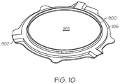
- FIG. 10 is a perspective view of a bearing flange portion of the housing assembly of FIGS. 1-3 .
- Embodiments of the subject matter described herein relate to a multilayer sheet metal housing for use with a rotary member of a flow control device, such as a compressor impeller in a turbocharger system. While the subject matter is described herein in the context of the housing being utilized as a compressor housing that houses an impeller or compressor wheel; however, it should be appreciated that the nomenclature is not intended to be limiting, and in various practical or alternative embodiments, the housing could be utilized to house a wheel of a turbine or other types of rotary elements.
- the compressor housing includes a pair of sheet metal shells that cooperatively define boundaries of a volute passage that radially directs and discharges a compressed flow from the housing.
- An inlet sheet metal structure includes a base portion that resides between the sheet metal shells and is affixed to one of the sheet metal shells via an intermediate sheet metal structure.
- the intermediate structure joins the base portion of the inlet structure to one of the sheet metal shells.
- the other of the volute sheet metal shells includes an impeller opening opposite the inlet to accommodate or otherwise receive at least the nose portion of the impeller of the compressor when the housing is mounted to an assembly including the impeller.
- the base portion of the inlet structure is effectively suspended above the impeller blades and the opposing volute sheet metal shell by a gap that provides clearance for the blades to rotate and provide a compressed fluid flow to the volute passage.
- an opening in the base portion is coaxially aligned with the rotational axis of the impeller.
- a surface of the intermediate sheet metal structure is contoured to define at least a portion of the volute in conjunction with the sheet metal shells.
- the intermediate structure is annular and circumscribes an inlet portion of the inlet structure that extends axially away from the impeller through the intermediate structure.
- the inlet portion includes a hollow cylindrical portion that is integral and concentric with the circumference of the opening in the base portion.
- the cylindrical portion extends axially away from the base portion for a distance that achieves a clearance with respect to the volute, and then an integral frustoconical portion extends axially from the cylindrical portion to increase the circumference of the inlet opening to the compressor housing.
- the term “axial” refers to a direction that is generally parallel to or coincident with an axis of rotation, axis of symmetry, or centerline of a component or components.
- the “axial” direction may refer to the direction that generally extends in parallel to the centerline between the opposite ends or faces.
- the term “axial” may be utilized with respect to components that are not cylindrical (or otherwise radially symmetric).
- the “axial” direction for a housing containing a rotating member may be viewed as a direction that is generally parallel to or coincident with the rotational axis of the rotating member.
- radially may refer to a direction or a relationship of components with respect to a line extending outward from a shared centerline, axis, or similar reference, for example in a plane of a cylinder or disc that is perpendicular to the centerline or axis.
- components may be viewed as “radially” aligned even though one or both of the components may not be cylindrical (or otherwise radially symmetric).
- axial and radial (and any derivatives) may encompass directional relationships that are other than precisely aligned with (e.g., oblique to) the true axial and radial dimensions, provided the relationship is predominately in the respective nominal axial or radial direction.
- the term “inner” may be utilized herein to refer to elements, features, or surfaces that are relatively closer to or generally face, in the axial direction, the impeller or rotating assembly that the compressor housing is mounted or otherwise joined to, while the term “outer” may be utilized herein to refer to elements, features, or surfaces that are relatively farther from or generally face away from the impeller or rotating assembly in the axial direction.
- the term “interior” may be utilized herein to refer to elements, features, or surfaces that are relatively closer to the axis of rotation associated with the impeller or generally face radially inward, while the term “peripheral” may be utilized herein to refer to elements, features, or surfaces that are relatively farther from or generally face away from axis of rotation.
- the drawings are merely illustrative and may not be drawn to scale.
- the figures shown herein depict an example with certain arrangements of elements, additional intervening elements, devices, features, or components may be present in an actual embodiment.
- FIGS. 1-3 depict an exemplary embodiment of a multilayer housing 100 suitable for use with a rotating flow control apparatus in a turbocharger system, such as a compressor.
- a turbocharger system such as a compressor.
- the subject matter is described herein in the context of the housing 100 being utilized as a compressor housing that houses an impeller or compressor wheel; however, it should be appreciated that the nomenclature is not intended to be limiting, and in various practical or alternative embodiments, the housing 100 could be utilized with a turbine.
- the compressor housing 100 includes a pair of metal shell structures 102 , 104 that are joined about their periphery and define a volute passage that radially directs a compressed flow to be discharged from the housing 100 at a discharge opening 101 defined by the shells 102 , 104 .
- a first metal shell 102 that is distal to the impeller is referred to herein as the outer volute portion (or outer volute) of the housing 100 while the opposing metal shell 104 that is proximate to the impeller is referred to herein as the inner volute portion (or inner volute).
- the volute portions 102 , 104 each include an interior opening having a central axis that is substantially aligned or coincident with the rotational axis of the impeller.
- the inner volute portion 104 is joined to a bearing flange 106 that supports joining or mounting the compressor housing 100 to a rotating assembly that includes an impeller or compressor wheel.
- the interior opening in the inner volute portion 104 accommodates at least a nose of the impeller upon insertion of the impeller when the bearing flange 106 is mounted to the rotating assembly.
- the opening in the outer volute portion 102 is configured to accommodate an inlet flange structure 108 , which defines an interior inlet opening 103 having a central axis that is substantially aligned or coincident with the rotational axis of the impeller to supply an input fluid flow to the impeller.
- a portion of the nose of the impeller may extend into the proximal end of the inlet opening 103 within a base portion 112 of the inlet flange 108 .
- An inlet portion of the inlet flange 108 includes a substantially cylindrical portion 114 that extends axially away from the base portion 112 to achieve clearance with respect to the outer volute portion 102 in a radial plane.
- the inlet portion of the inlet flange 108 also includes a frustoconical portion 116 that extends axially away from the cylindrical portion 114 to progressively increase the diameter of the inlet opening 103 towards the end of the inlet opening 103 distal to the impeller.
- the base portion 112 of the inlet flange 108 is joined to an intermediate sheet metal structure 110 , which, in turn, is joined to the outer volute portion 102 so that the base portion 112 is suspended above the impeller to provide clearance for the impeller blades.
- a nonzero separation distance or gap exists in the axial direction between the substantially planar base portion 112 of the inlet flange 108 and a radial plane associated with the interface between the inner volute portion 104 and the bearing flange 106 (or alternatively, a plane aligned with the inner end of the opening in the inner volute portion 104 proximate the bearing flange 106 ).
- a peripheral surface of the intermediate metal portion 110 is contoured to provide an interior contour of the volute to support radially directing a compressed flow from the impeller. Accordingly, the intermediate metal structure 110 is alternatively referred to herein as the core volute portion (or core volute).
- FIGS. 4-5 depict plan views of the outer volute portion 102 .
- the outer volute portion 102 is realized as a substantially spiral structure formed from sheet metal to include a body portion 300 that spirals about an interior opening 301 into a discharge portion 302 that extends tangentially from the body portion 300 .
- the inner surface 303 of the outer volute portion 102 is contoured or otherwise pressed to provide a substantially U-shaped cross-section that defines a portion of a volute passage for radially directing a compressed flow from an initiating end 304 of the spiral into the discharge portion 302 and discharge opening 101 .
- the depth or dimension of the U-shaped cross-section relative to a peripheral edge 306 progressively increases from the initiating end 304 towards the discharge portion 302 to increase the flow area (or reduce resistance) and thereby direct a compressed flow out the discharge opening 101 .
- the body 300 of the outer volute 102 spirals in an axial direction away from the impeller so that the discharge portion 302 is axially inclined relative to the initiating end 304 , and in some embodiments, overlaps the initiating end 304 of the body portion 300 .
- the interior opening 301 is substantially circular and centered on the axis of rotation for the impeller, however, in alternative embodiments, the opening 301 may be off center and/or non-circular.
- the diameter of the opening 301 defined by the spiral is greater than a diameter of the cylindrical portion 114 of the inlet flange 108 and the opening end of the frustoconical portion 116 , but the circumference of the opening 301 is less than or equal to the peripheral circumference of the base portion 112 .
- the edges 306 , 308 , 310 of the outer volute portion 102 include or are realized as a rim, lip, or similar feature providing an inner surface substantially aligned in a radial plane for joining the outer volute portion 102 to the other volute portions 104 , 110 with joints correspondingly aligned in a substantially radial plane.
- the peripheral edges 306 , 308 are joined to peripheral edges of the inner volute portion 104 while the interior edge 310 is joined to the core volute portion 110 .
- FIGS. 6-7 depict plan views of the inner volute portion 104 .
- the inner volute 104 is realized as a substantially spiral structure formed from sheet metal to include a body portion 500 that spirals about an interior opening 501 into a discharge portion 502 that extends tangentially from the body portion 500 .
- the outer surface 503 of the inner volute portion 104 that faces the outer volute surface 303 is contoured or otherwise pressed to define another portion of the volute radially directing a compressed flow from an initiating end of the spiral to a substantially U-shaped cross-section at the opening end of the discharge portion 502 .
- the depth or dimension of the contoured surface 503 relative to a peripheral edge 506 progressively increases towards the discharge end to increase the flow area (or reduce resistance) and thereby direct a compressed flow out the discharge opening 101 .
- the opening 501 is substantially circular and centered on the axis of rotation for the impeller, however, in alternative embodiments, the opening 501 may be off center and/or non-circular. In one or more embodiments, the openings 301 , 501 in the volute portions 102 , 104 are concentric.
- the interior circumference of the impeller opening 501 is less than or equal to the circumference of an opening in the bearing flange 106 about which the inner volute portion 104 and the bearing flange 106 are joined.
- the interior edge 510 of the body portion 500 that defines the impeller opening 501 includes a rim, lip, or similar feature that extends in an axial direction towards the bearing flange 106 to provide an inner surface substantially aligned in an axial plane for joining the inner volute portion 104 to a corresponding feature of the bearing flange 106 , as described in greater detail below.
- the peripheral edges 506 , 508 of the inner volute portion 104 include a rim, lip, or similar feature providing an inner surface substantially aligned in a radial plane for axially joining the inner volute portion 104 to the outer volute portion 102 at edges 306 , 308 .
- the core volute portion 110 is realized as a substantially annular structure including a central opening 701 .
- the core volute 110 is pressed or otherwise formed to provide an outer edge portion 700 with a substantially flat surface that spirals in an axial direction in a manner corresponding to the interior edge 310 of the outer volute 102 to support joining the outer edge 700 with the counterpart interior edge 310 of the outer volute 102 .
- the outer edge 700 includes a portion 706 that projects in an axial direction and corresponds to or otherwise mates with the initiating end 304 of the outer volute spiral.
- a peripheral surface 704 of the core volute 110 faces the contoured surface 303 of the outer volute 102 and is similarly contoured to define the outer portion of the volute that radially directs compressed flow in conjunction with the outer volute surface 303 .
- the dimension of the peripheral surface 704 in the axial direction varies in a manner that corresponds to the spiraling of the interior edge 310 of the outer volute 102 in the axial direction.
- the dimension of the peripheral surface 704 in the axial direction progressively increases from the initiating end 304 of the spiral until the interior edge 310 overlaps the initiating end 304 of the outer volute 102 at the interface to the discharge portion 302 , with the dimension or depth of the contouring in the peripheral surface 704 corresponding to the axial dimension of the core volute 110 .
- the outer circumference of the opening 701 defined by the edge portion 700 is substantially equal to the inner circumference of the opening 301 , such that the outer circumference of the core volute opening 701 and the inner circumference of the outer volute opening 301 are concentric and symmetric.
- the core volute opening 701 is substantially circular and centered on the axis of rotation for the impeller, however, in alternative embodiments, the core volute opening 701 may be off center and/or non-circular. Similar to the outer volute opening 301 , the circumference or diameter of the core volute opening 701 is greater than the circumference or diameter of the cylindrical portion 114 of the inlet flange 108 .
- an inner edge portion 702 of the core volute 110 is configured to provide a rim, lip, or similar feature that extends from the body of the core volute 110 in an axial direction to support joining the inner edge portion 702 to a corresponding feature 800 of the base portion 112 of the inlet flange 108 .
- the inner circumference of the core volute opening 701 defined by the inner edge 702 is greater than the outer circumference and substantially equal to a peripheral circumference of the base portion 112 .
- the inner rim 702 of the core volute 110 and the peripheral rim 800 of the inlet base portion 112 may be concentric and symmetric.
- the axially extending portions 114 , 116 of the inlet flange 108 extend through the core volute opening 701 to provide an inlet opening 103 with sufficient clearance for joining or otherwise mounting an intake conduit to the outer end of the inlet flange 108 .
- the outer end of the frustoconical portion 116 includes a rim, lip, or similar feature 802 that supports joining the inlet flange 108 to an external conduit at the inlet opening 103 .
- the bearing flange 106 is generally realized as an annular plate-like structure having a central opening 901 for receiving at least the nose portion of the impeller when the bearing flange 106 is mounted to a rotating assembly including the impeller.
- substantially the entirety of the impeller may extend through the opening 901 in the axial direction, such that the opening 901 substantially circumscribes the blades of the impeller.
- the circumference of the interior edge 900 of the bearing flange 106 that defines the opening 901 may be greater than the circumference of the impeller.
- the interior edge 900 includes or is otherwise realized as a rim, lip, or similar feature that extends in the axial direction to engage the counterpart feature 510 of the inner volute 104 .
- the rim 900 of the bearing flange 106 and the inner rim 510 of the inner volute 104 may be concentric and symmetric, such that the circumference of the bearing flange opening 901 and the inner circumference of the inner volute opening 501 are substantially equal.
- the bearing flange 106 may also include a peripheral rim, lip, or similar feature 902 that is shaped or otherwise formed to support mounting the compressor housing 100 to the rotating assembly. That said, the physical characteristics and mounting features of the peripheral rim 902 are not germane to the subject matter and will not be described in detail herein.
- each of the structures 102 , 104 , 106 , 108 , 110 are formed from respective metal structures, that is, each of the structures 102 , 104 , 106 , 108 , 110 are formed from a separate piece of sheet metal.
- each of the structures 102 , 104 , 106 , 108 , 110 are formed from sheets of the same type of metal material; however, in alternative embodiments, different metal materials may be utilized for different structures 102 , 104 , 106 , 108 , 110 .
- each of the structures 102 , 104 , 106 , 108 , 110 are formed from sheet metals having the same initial thickness, however, in alternative embodiments, different sheet metal thicknesses may be utilized for different structures 102 , 104 , 106 , 108 , 110 .
- each of the structures 102 , 104 , 106 , 108 , 110 is realized as type 302 stainless steel formed from sheets having substantially the same thickness, and in one or more exemplary embodiments, the thicknesses are in the range of about 1.0 millimeters to 1.5 millimeters. That said, different types of sheet metal and different thicknesses thereof may be utilized in practice depending on the needs or objectives of a particular embodiment.
- the individual metal sheets are then individually machined, tooled, or otherwise formed into the respective structures 102 , 104 , 106 , 108 , 110 described above.
- the inlet flange 108 may be formed by metal spinning while the volute portions 102 , 104 , 110 and the bearing flange 106 are formed by multistage tooling (e.g., spinning, blanking, bending, stamping, machining, punching, and the like).
- multistage tooling e.g., spinning, blanking, bending, stamping, machining, punching, and the like.
- different types of tooling may be utilized for different structures 102 , 104 , 106 , 108 , 110 .
- the structures 102 , 104 , 106 , 108 , 110 are individually formed by 3D printing using sheet metal.
- the structures 102 , 104 , 106 , 108 , 110 are assembled as depicted in FIG. 3 and joined as depicted in FIGS. 1-2 using a filler metal before furnace brazing to form joints between counterpart features of the various structures 102 , 104 , 106 , 108 , 110 .
- filler metal is provided at or between the interface between the inner rim 702 of the core volute 110 and its counterpart peripheral rim 800 of the inlet base portion 112 to form a joint between the inner edge of the core volute 110 and the outer surface of the inlet base portion 112 .
- Filler metal is also provided at or between the interface between the outer rim 700 of the core volute 110 and the counterpart interior rim 310 of the outer volute 102 to form a joint between the outer edge of the core volute 110 and an inner surface of the outer volute 102 .
- Filler metal is provided at or between the interface between the peripheral rims 306 , 308 of the outer volute 102 and the counterpart peripheral rims 506 , 508 of the inner volute 104 to form a joint between the volute portions 102 , 104 that hermetically seals the volute and discharge chambers of the housing 100 , while filler metal is provided at or between the interface between the interior rim 510 of the inner volute 104 and the counterpart interior rim 900 of the bearing flange 106 to form a joint about the opening 901 that receives the impeller.
- the housing 100 is provided or conveyed into a furnace that concurrently brazes the joints between structures 102 , 104 , 106 , 108 , 110 by heating the housing 100 and thereby melting the filler metal.
- the brazed joints hermetically seal the interfaces between structures 102 , 104 , 106 , 108 , 110 .
- compressor housing 100 may be formed by welding the structures 102 , 104 , 106 , 108 , 110 together or otherwise using alternative metal joining techniques in lieu of furnace brazing.
- compressor housings may be formed from a malleable ferrous alloy by sheet metal forming technology, as compared to cast housings. Additionally, the resulting compressor housing may exhibit increased rigidity without compromising performance. For example, stainless steel sheet metal may exhibit higher rigidity and superior mechanical properties relative to aluminum alloys or other materials that may be utilized in a cast compressor housing.
Landscapes
- Engineering & Computer Science (AREA)
- Mechanical Engineering (AREA)
- General Engineering & Computer Science (AREA)
- Structures Of Non-Positive Displacement Pumps (AREA)
Abstract
Description
Claims (20)
Priority Applications (3)
| Application Number | Priority Date | Filing Date | Title |
|---|---|---|---|
| US15/634,493 US10690144B2 (en) | 2017-06-27 | 2017-06-27 | Compressor housings and fabrication methods |
| EP18171962.6A EP3447305B1 (en) | 2017-06-27 | 2018-05-11 | Compressor housings and fabrication methods |
| CN201810548420.1A CN109139557B (en) | 2017-06-27 | 2018-05-31 | Compressor housing and method of manufacture |
Applications Claiming Priority (1)
| Application Number | Priority Date | Filing Date | Title |
|---|---|---|---|
| US15/634,493 US10690144B2 (en) | 2017-06-27 | 2017-06-27 | Compressor housings and fabrication methods |
Publications (2)
| Publication Number | Publication Date |
|---|---|
| US20180372116A1 US20180372116A1 (en) | 2018-12-27 |
| US10690144B2 true US10690144B2 (en) | 2020-06-23 |
Family
ID=62165372
Family Applications (1)
| Application Number | Title | Priority Date | Filing Date |
|---|---|---|---|
| US15/634,493 Active 2038-07-06 US10690144B2 (en) | 2017-06-27 | 2017-06-27 | Compressor housings and fabrication methods |
Country Status (3)
| Country | Link |
|---|---|
| US (1) | US10690144B2 (en) |
| EP (1) | EP3447305B1 (en) |
| CN (1) | CN109139557B (en) |
Cited By (2)
| Publication number | Priority date | Publication date | Assignee | Title |
|---|---|---|---|---|
| US20220034239A1 (en) * | 2019-04-17 | 2022-02-03 | Ihi Corporation | Turbine housing and turbocharger |
| EP4033074A1 (en) * | 2021-01-26 | 2022-07-27 | Garrett Transportation I Inc. | Sheet metal turbine housing |
Families Citing this family (7)
| Publication number | Priority date | Publication date | Assignee | Title |
|---|---|---|---|---|
| DE102018221554A1 (en) * | 2018-12-12 | 2020-06-18 | BMTS Technology GmbH & Co. KG | Exhaust gas turbocharger |
| USD902961S1 (en) * | 2019-03-01 | 2020-11-24 | Savant Holdings LLC | Compressor housing |
| US10927702B1 (en) | 2019-03-30 | 2021-02-23 | Savant Holdings LLC | Turbocharger or turbocharger component |
| CN110671159A (en) * | 2019-09-18 | 2020-01-10 | 无锡康明斯涡轮增压技术有限公司 | Turbocharger volute |
| USD900163S1 (en) * | 2020-02-20 | 2020-10-27 | Savant Holdings LLC | Compressor housing |
| CN111536078A (en) * | 2020-05-20 | 2020-08-14 | 西安交通大学 | Spiral volute of centrifugal fan |
| US12215711B1 (en) * | 2024-01-04 | 2025-02-04 | Vacuum Technologies, Llc | Carwash vacuum motor |
Citations (44)
| Publication number | Priority date | Publication date | Assignee | Title |
|---|---|---|---|---|
| US1707719A (en) | 1928-05-15 | 1929-04-02 | B F Sturtevant Co | Fan casing |
| JPS61132800A (en) | 1984-11-29 | 1986-06-20 | Mitsubishi Heavy Ind Ltd | Compressor housing for supercharger and manufacture thereof |
| DE29909018U1 (en) | 1999-05-26 | 2000-09-28 | Heinrich Gillet GmbH & Co. KG, 67480 Edenkoben | Turbine housing for exhaust gas turbochargers |
| US6193463B1 (en) * | 1999-06-30 | 2001-02-27 | Alliedsignal, Inc. | Die cast compressor housing for centrifugal compressors with a true volute shape |
| WO2001094754A1 (en) | 2000-06-07 | 2001-12-13 | Borgwarner, Inc. | Casing assembly for the turbine of an exhaust turbocharger |
| JP2002004871A (en) | 2000-04-19 | 2002-01-09 | Aisin Takaoka Ltd | Turbine housing for supercharger |
| JP2002054447A (en) | 2000-08-09 | 2002-02-20 | Aisin Takaoka Ltd | Turbine housing |
| JP2002349276A (en) | 2001-05-25 | 2002-12-04 | Aisin Takaoka Ltd | Turbine housing |
| US6553762B2 (en) | 2000-12-12 | 2003-04-29 | Daimlerchrysler A.G. | Exhaust gas turbocharger for an internal combustion engine |
| JP2003293779A (en) | 2002-03-29 | 2003-10-15 | Toyota Motor Corp | Turbine housing |
| JP2003293780A (en) | 2002-03-29 | 2003-10-15 | Toyota Motor Corp | Turbine housing |
| WO2004109062A1 (en) | 2003-06-06 | 2004-12-16 | Ihi Charging Systems International Gmbh | Exhaust gas turbine for an exhaust gas turbocharger |
| EP1500788A1 (en) | 2003-07-23 | 2005-01-26 | BorgWarner Inc. | Double flow scroll |
| EP1541826A1 (en) | 2003-12-13 | 2005-06-15 | Ford Global Technologies, LLC | Turbocharger |
| US6951450B1 (en) | 2000-07-19 | 2005-10-04 | Honeywell International, Inc. | Variable geometry turbocharger |
| EP1450017B1 (en) | 2003-02-20 | 2005-12-07 | Benteler Automobiltechnik GmbH | Arrangement to direct exhaust gas from combustion engine to exhaust line |
| JP2006161573A (en) | 2004-12-02 | 2006-06-22 | Toyota Motor Corp | Turbocharger turbine housing |
| US7198459B2 (en) | 2003-11-13 | 2007-04-03 | Benteler Automobiltechnik Gmbh | Casing arrangement for a turbocharger of an internal combustion engine |
| US20070113550A1 (en) | 2003-10-24 | 2007-05-24 | Lorrain Sausee | Turbocharger with a thin-walled turbine housing having a floating flange attachment to the centre housing |
| US7234302B2 (en) | 2002-12-03 | 2007-06-26 | Borgwarner Inc. | Housing for a turbocharger |
| CA2578420A1 (en) | 2007-02-08 | 2008-08-08 | Mike Flynn | Method of die casting compressor housings |
| WO2009114568A2 (en) | 2008-03-13 | 2009-09-17 | Borgwarner Inc. | Exhaust manifold of an internal combustion engine |
| DE102009042260A1 (en) | 2009-09-22 | 2011-04-07 | Benteler Automobiltechnik Gmbh | turbocharger |
| US20120000251A1 (en) | 2010-06-30 | 2012-01-05 | The Hong Kong Polytechnic University | Items of clothing having shape memory |
| US20120288364A1 (en) * | 2010-02-04 | 2012-11-15 | Toyota Jidosha Kabushiki Kaisha | Turbocharger and turbocharger wheel housing |
| US8419359B2 (en) * | 2007-06-11 | 2013-04-16 | Woco Industrietechnik Gmbh | Plastic compressor housing and method for producing a plastic compressor housing |
| US20130108414A1 (en) | 2011-11-02 | 2013-05-02 | Toyota Jidosha Kabushiki Kaisha | Turbine housing and exhaust gas turbine supercharger |
| EP2180163B1 (en) | 2008-10-21 | 2013-06-05 | Benteler Automobiltechnik GmbH | Turbine housing and method for its production |
| US20130189093A1 (en) * | 2012-01-23 | 2013-07-25 | Ford Global Technologies, Llc | Multi-piece twin scroll turbine |
| DE102004039477B4 (en) | 2004-08-14 | 2015-01-08 | Ihi Charging Systems International Gmbh | Turbine housing for an exhaust gas turbocharger |
| EP2832886A1 (en) | 2012-03-30 | 2015-02-04 | Nippon Steel & Sumikin Stainless Steel Corporation | Heat-resistant austenitic stainless steel sheet |
| US20150044034A1 (en) | 2012-03-23 | 2015-02-12 | Mitsubishi Heavy Industries, Ltd. | Turbine housing assembly |
| US20150086347A1 (en) * | 2012-03-23 | 2015-03-26 | Mitsubishi Heavy Industries, Ltd. | Turbine housing assembly and manufacturing method of turbine housing assembly |
| US9097181B2 (en) | 2011-05-19 | 2015-08-04 | Benteler Automobil Technik Gmbh | Turbine housing of an exhaust-gas turbocharger |
| US9194292B2 (en) | 2009-12-21 | 2015-11-24 | Mitsubishi Heavy Industries, Ltd. | Turbine housing |
| DE102009025054B4 (en) | 2009-06-10 | 2015-12-03 | Benteler Automobiltechnik Gmbh | turbine housing |
| WO2015185408A1 (en) | 2014-06-02 | 2015-12-10 | Mitsubishi Turbocharger And Engine Europe B.V. | A spiral turbine casing of a turbocharger |
| US9234459B2 (en) * | 2010-01-15 | 2016-01-12 | Toyota Jidosha Kabushiki Kaisha | Turbocharger and wheel housing |
| US9255485B2 (en) * | 2011-02-02 | 2016-02-09 | Mitsubishi Heavy Industries, Ltd. | Turbine housing made of sheet metal |
| US9261109B2 (en) | 2011-07-06 | 2016-02-16 | Toyota Jidosha Kabushiki Kaisha | Turbine housing and exhaust gas turbine supercharger |
| JP2016031027A (en) | 2014-07-28 | 2016-03-07 | 株式会社三五 | Turbine housing |
| US20160258447A1 (en) * | 2013-10-31 | 2016-09-08 | Borgwarner Inc. | Noise attenuation device for compressor inlet duct |
| WO2017078088A1 (en) | 2015-11-06 | 2017-05-11 | カルソニックカンセイ株式会社 | Turbine housing |
| US20190113050A1 (en) * | 2017-10-17 | 2019-04-18 | Borgwarner Inc. | Multi-Piece Compressor Housing for a Turbocharger |
Family Cites Families (4)
| Publication number | Priority date | Publication date | Assignee | Title |
|---|---|---|---|---|
| GB0912796D0 (en) * | 2009-07-23 | 2009-08-26 | Cummins Turbo Tech Ltd | Compressor,turbine and turbocharger |
| WO2012170754A1 (en) * | 2011-06-10 | 2012-12-13 | Borgwarner Inc. | Double flow turbine housing turbocharger |
| US9631625B2 (en) * | 2013-02-01 | 2017-04-25 | Honeywell International Inc. | Axial turbine with statorless inlet formed by meridionally divided turbine housing and heat shroud |
| GB201409976D0 (en) * | 2014-06-05 | 2014-07-16 | Cummins Ltd | Method of manufacturing a compressor housing |
-
2017
- 2017-06-27 US US15/634,493 patent/US10690144B2/en active Active
-
2018
- 2018-05-11 EP EP18171962.6A patent/EP3447305B1/en active Active
- 2018-05-31 CN CN201810548420.1A patent/CN109139557B/en active Active
Patent Citations (58)
| Publication number | Priority date | Publication date | Assignee | Title |
|---|---|---|---|---|
| US1707719A (en) | 1928-05-15 | 1929-04-02 | B F Sturtevant Co | Fan casing |
| JPS61132800A (en) | 1984-11-29 | 1986-06-20 | Mitsubishi Heavy Ind Ltd | Compressor housing for supercharger and manufacture thereof |
| DE29909018U1 (en) | 1999-05-26 | 2000-09-28 | Heinrich Gillet GmbH & Co. KG, 67480 Edenkoben | Turbine housing for exhaust gas turbochargers |
| FR2795769A1 (en) | 1999-05-26 | 2001-01-05 | Heinrich Gillet Gmbh Co Kg | Turbine casing for exhaust gas turbocharger has inlet funnel, rotor casing and exhaust pipe made from embossed or deep-drawn sheet metal, and inlet funnel and exhaust pipe are welded to rotor casing which comprises two half shells |
| DE10022052A1 (en) | 1999-05-26 | 2001-03-01 | Gillet Heinrich Gmbh | Turbine casing for exhaust gas turbocharger has inlet funnel, rotor casing and exhaust pipe made from embossed or deep-drawn sheet metal, and inlet funnel and exhaust pipe are welded to rotor casing which comprises two half shells |
| US6193463B1 (en) * | 1999-06-30 | 2001-02-27 | Alliedsignal, Inc. | Die cast compressor housing for centrifugal compressors with a true volute shape |
| JP2002004871A (en) | 2000-04-19 | 2002-01-09 | Aisin Takaoka Ltd | Turbine housing for supercharger |
| WO2001094754A1 (en) | 2000-06-07 | 2001-12-13 | Borgwarner, Inc. | Casing assembly for the turbine of an exhaust turbocharger |
| US6951450B1 (en) | 2000-07-19 | 2005-10-04 | Honeywell International, Inc. | Variable geometry turbocharger |
| EP1303683B1 (en) | 2000-07-19 | 2008-07-30 | Honeywell International Inc. | Variable nozzle turbocharger with sheet metal shroud |
| JP2002054447A (en) | 2000-08-09 | 2002-02-20 | Aisin Takaoka Ltd | Turbine housing |
| US6553762B2 (en) | 2000-12-12 | 2003-04-29 | Daimlerchrysler A.G. | Exhaust gas turbocharger for an internal combustion engine |
| JP2002349276A (en) | 2001-05-25 | 2002-12-04 | Aisin Takaoka Ltd | Turbine housing |
| JP2003293779A (en) | 2002-03-29 | 2003-10-15 | Toyota Motor Corp | Turbine housing |
| JP2003293780A (en) | 2002-03-29 | 2003-10-15 | Toyota Motor Corp | Turbine housing |
| US7234302B2 (en) | 2002-12-03 | 2007-06-26 | Borgwarner Inc. | Housing for a turbocharger |
| EP1426557B1 (en) | 2002-12-03 | 2013-07-17 | BorgWarner, Inc. | Casing for turbo charger |
| EP1450017B8 (en) | 2003-02-20 | 2006-06-07 | Benteler Automobiltechnik GmbH | Arrangement to direct exhaust gas from combustion engine to exhaust line |
| EP1450017B1 (en) | 2003-02-20 | 2005-12-07 | Benteler Automobiltechnik GmbH | Arrangement to direct exhaust gas from combustion engine to exhaust line |
| US20060133931A1 (en) | 2003-06-06 | 2006-06-22 | Hermann Burmester | Exhaust gas turbine for an exhaust gas turbocharger |
| US7371047B2 (en) | 2003-06-06 | 2008-05-13 | Ihi Charging Systems International Gmbh | Exhaust gas turbine for an exhaust gas turbocharger |
| WO2004109062A1 (en) | 2003-06-06 | 2004-12-16 | Ihi Charging Systems International Gmbh | Exhaust gas turbine for an exhaust gas turbocharger |
| EP1631736B1 (en) | 2003-06-06 | 2015-07-29 | IHI Charging Systems International GmbH | Exhaust gas turbine for an exhaust gas turbocharger |
| US20050019158A1 (en) | 2003-07-23 | 2005-01-27 | Hartmut Claus | Twin flow turbine housing |
| EP1500788A1 (en) | 2003-07-23 | 2005-01-26 | BorgWarner Inc. | Double flow scroll |
| US20070113550A1 (en) | 2003-10-24 | 2007-05-24 | Lorrain Sausee | Turbocharger with a thin-walled turbine housing having a floating flange attachment to the centre housing |
| US7198459B2 (en) | 2003-11-13 | 2007-04-03 | Benteler Automobiltechnik Gmbh | Casing arrangement for a turbocharger of an internal combustion engine |
| US20050126163A1 (en) | 2003-12-13 | 2005-06-16 | Bjornsson Hakan Sr. | Turbocharger |
| EP1541826A1 (en) | 2003-12-13 | 2005-06-15 | Ford Global Technologies, LLC | Turbocharger |
| DE102004039477B4 (en) | 2004-08-14 | 2015-01-08 | Ihi Charging Systems International Gmbh | Turbine housing for an exhaust gas turbocharger |
| JP2006161573A (en) | 2004-12-02 | 2006-06-22 | Toyota Motor Corp | Turbocharger turbine housing |
| CA2578420A1 (en) | 2007-02-08 | 2008-08-08 | Mike Flynn | Method of die casting compressor housings |
| US8419359B2 (en) * | 2007-06-11 | 2013-04-16 | Woco Industrietechnik Gmbh | Plastic compressor housing and method for producing a plastic compressor housing |
| WO2009114568A2 (en) | 2008-03-13 | 2009-09-17 | Borgwarner Inc. | Exhaust manifold of an internal combustion engine |
| EP2180163B1 (en) | 2008-10-21 | 2013-06-05 | Benteler Automobiltechnik GmbH | Turbine housing and method for its production |
| DE102009025054B4 (en) | 2009-06-10 | 2015-12-03 | Benteler Automobiltechnik Gmbh | turbine housing |
| US8628296B2 (en) | 2009-09-22 | 2014-01-14 | Benteler Automobiltechnik Gmbh | Exhaust-gas turbocharger |
| DE102009042260A1 (en) | 2009-09-22 | 2011-04-07 | Benteler Automobiltechnik Gmbh | turbocharger |
| DE102009042260B4 (en) | 2009-09-22 | 2015-12-10 | Benteler Automobiltechnik Gmbh | turbocharger |
| US9194292B2 (en) | 2009-12-21 | 2015-11-24 | Mitsubishi Heavy Industries, Ltd. | Turbine housing |
| US9234459B2 (en) * | 2010-01-15 | 2016-01-12 | Toyota Jidosha Kabushiki Kaisha | Turbocharger and wheel housing |
| US20120288364A1 (en) * | 2010-02-04 | 2012-11-15 | Toyota Jidosha Kabushiki Kaisha | Turbocharger and turbocharger wheel housing |
| US9121281B2 (en) | 2010-02-04 | 2015-09-01 | Toyota Jidosha Kabushiki Kaisha | Turbocharger and turbocharger wheel housing |
| US20120000251A1 (en) | 2010-06-30 | 2012-01-05 | The Hong Kong Polytechnic University | Items of clothing having shape memory |
| US9255485B2 (en) * | 2011-02-02 | 2016-02-09 | Mitsubishi Heavy Industries, Ltd. | Turbine housing made of sheet metal |
| US9097181B2 (en) | 2011-05-19 | 2015-08-04 | Benteler Automobil Technik Gmbh | Turbine housing of an exhaust-gas turbocharger |
| US9261109B2 (en) | 2011-07-06 | 2016-02-16 | Toyota Jidosha Kabushiki Kaisha | Turbine housing and exhaust gas turbine supercharger |
| DE112011105790T5 (en) | 2011-11-02 | 2014-08-07 | Toyota Jidosha Kabushiki Kaisha | Turbine housing and exhaust gas turbocharger |
| US20130108414A1 (en) | 2011-11-02 | 2013-05-02 | Toyota Jidosha Kabushiki Kaisha | Turbine housing and exhaust gas turbine supercharger |
| US20130189093A1 (en) * | 2012-01-23 | 2013-07-25 | Ford Global Technologies, Llc | Multi-piece twin scroll turbine |
| US20150044034A1 (en) | 2012-03-23 | 2015-02-12 | Mitsubishi Heavy Industries, Ltd. | Turbine housing assembly |
| US20150086347A1 (en) * | 2012-03-23 | 2015-03-26 | Mitsubishi Heavy Industries, Ltd. | Turbine housing assembly and manufacturing method of turbine housing assembly |
| EP2832886A1 (en) | 2012-03-30 | 2015-02-04 | Nippon Steel & Sumikin Stainless Steel Corporation | Heat-resistant austenitic stainless steel sheet |
| US20160258447A1 (en) * | 2013-10-31 | 2016-09-08 | Borgwarner Inc. | Noise attenuation device for compressor inlet duct |
| WO2015185408A1 (en) | 2014-06-02 | 2015-12-10 | Mitsubishi Turbocharger And Engine Europe B.V. | A spiral turbine casing of a turbocharger |
| JP2016031027A (en) | 2014-07-28 | 2016-03-07 | 株式会社三五 | Turbine housing |
| WO2017078088A1 (en) | 2015-11-06 | 2017-05-11 | カルソニックカンセイ株式会社 | Turbine housing |
| US20190113050A1 (en) * | 2017-10-17 | 2019-04-18 | Borgwarner Inc. | Multi-Piece Compressor Housing for a Turbocharger |
Non-Patent Citations (1)
| Title |
|---|
| European Patent and Trademark Office, European Search Report for Application No. 18171962.6 dated Jan. 25, 2019. |
Cited By (5)
| Publication number | Priority date | Publication date | Assignee | Title |
|---|---|---|---|---|
| US20220034239A1 (en) * | 2019-04-17 | 2022-02-03 | Ihi Corporation | Turbine housing and turbocharger |
| US11808163B2 (en) * | 2019-04-17 | 2023-11-07 | Ihi Corporation | Turbine housing and turbocharger |
| EP4033074A1 (en) * | 2021-01-26 | 2022-07-27 | Garrett Transportation I Inc. | Sheet metal turbine housing |
| US20220235793A1 (en) * | 2021-01-26 | 2022-07-28 | Garrett Transportation I Inc | Sheet metal turbine housing |
| US11732729B2 (en) * | 2021-01-26 | 2023-08-22 | Garrett Transportation I Inc | Sheet metal turbine housing |
Also Published As
| Publication number | Publication date |
|---|---|
| US20180372116A1 (en) | 2018-12-27 |
| EP3447305A1 (en) | 2019-02-27 |
| EP3447305B1 (en) | 2024-02-14 |
| CN109139557A (en) | 2019-01-04 |
| CN109139557B (en) | 2025-07-29 |
Similar Documents
| Publication | Publication Date | Title |
|---|---|---|
| US10690144B2 (en) | Compressor housings and fabrication methods | |
| EP1192360B1 (en) | Die cast compressor housing for centrifugal compressors with a true volute shape | |
| EP3354864B1 (en) | Sheet metal turbine housing with containment dampers | |
| EP3354855B1 (en) | Sheet metal turbine housing for a turbocharger | |
| US4322200A (en) | Heavy duty impeller | |
| US8251650B2 (en) | Compressor housing | |
| US9932857B2 (en) | Bearing holder having a axisymmetric sealable gimlet | |
| US9482239B2 (en) | Die-cast diffuser for a turbocharger | |
| CN107208543A (en) | Turbocharger | |
| US11035254B2 (en) | Sheet metal turbine housing with cast core | |
| EP3354861A2 (en) | Sheet metal turbine housing and related turbocharger systems | |
| CN110130999B (en) | Structural casing for an axial turbine engine | |
| JP2008309157A (en) | Turbine engine exhaust cowling | |
| US20190112927A1 (en) | Turbocharger having improved turbine wheel | |
| JP7097505B2 (en) | Nozzle device and exhaust turbocharger | |
| US11732731B2 (en) | Diffuser and deswirl system with integral tangential onboard injector for engine | |
| US10655634B2 (en) | Multi-piece compressor wheel | |
| CN109196230A (en) | Impeller, rotating machinery, turbocharger | |
| US11732729B2 (en) | Sheet metal turbine housing | |
| CN103850728A (en) | Turbomachine flow divider and related turbomachine |
Legal Events
| Date | Code | Title | Description |
|---|---|---|---|
| AS | Assignment |
Owner name: HONEYWELL INTERNATIONAL INC., NEW JERSEY Free format text: ASSIGNMENT OF ASSIGNORS INTEREST;ASSIGNORS:NANDAGOPAL, BALASUBRAMANI;REVANNA, BASAVARAJU;LAKKAPPA, JANARDHAM;REEL/FRAME:042828/0675 Effective date: 20170627 |
|
| STPP | Information on status: patent application and granting procedure in general |
Free format text: DOCKETED NEW CASE - READY FOR EXAMINATION |
|
| AS | Assignment |
Owner name: GARRETT TRANSPORTATION I INC., CALIFORNIA Free format text: ASSIGNMENT OF ASSIGNORS INTEREST;ASSIGNOR:HONEYWELL INTERNATIONAL INC.;REEL/FRAME:047024/0127 Effective date: 20180614 |
|
| AS | Assignment |
Owner name: GARRETT TRANSPORTATION I INC., CALIFORNIA Free format text: CORRECTIVE ASSIGNMENT TO CORRECT THE ASSIGNEE NAME AND EXECUTION DATE PREVIOUSLY RECORDED AT REEL: 046103 FRAME: 0144. ASSIGNOR(S) HEREBY CONFIRMS THE ASSIGNMENT;ASSIGNOR:HONEYWELL INTERNATIONAL INC.;REEL/FRAME:047119/0864 Effective date: 20180614 |
|
| AS | Assignment |
Owner name: JPMORGAN CHASE BANK, N.A., AS ADMINISTRATIVE AGENT, NEW YORK Free format text: SECURITY INTEREST;ASSIGNOR:GARRETT TRANSPORTATION I INC.;REEL/FRAME:047172/0220 Effective date: 20180927 Owner name: JPMORGAN CHASE BANK, N.A., AS ADMINISTRATIVE AGENT Free format text: SECURITY INTEREST;ASSIGNOR:GARRETT TRANSPORTATION I INC.;REEL/FRAME:047172/0220 Effective date: 20180927 |
|
| STPP | Information on status: patent application and granting procedure in general |
Free format text: NON FINAL ACTION MAILED |
|
| STPP | Information on status: patent application and granting procedure in general |
Free format text: RESPONSE TO NON-FINAL OFFICE ACTION ENTERED AND FORWARDED TO EXAMINER |
|
| STPP | Information on status: patent application and granting procedure in general |
Free format text: NOTICE OF ALLOWANCE MAILED -- APPLICATION RECEIVED IN OFFICE OF PUBLICATIONS |
|
| STPP | Information on status: patent application and granting procedure in general |
Free format text: PUBLICATIONS -- ISSUE FEE PAYMENT VERIFIED |
|
| STCF | Information on status: patent grant |
Free format text: PATENTED CASE |
|
| AS | Assignment |
Owner name: WILMINGTON SAVINGS FUND SOCIETY, FSB, AS SUCCESSOR ADMINISTRATIVE AND COLLATERAL AGENT, DELAWARE Free format text: ASSIGNMENT AND ASSUMPTION OF SECURITY INTEREST IN PATENTS;ASSIGNOR:JPMORGAN CHASE BANK, N.A., AS RESIGNING ADMINISTRATIVE AND COLLATERAL AGENT;REEL/FRAME:055008/0263 Effective date: 20210114 |
|
| AS | Assignment |
Owner name: GARRETT TRANSPORTATION I INC., CALIFORNIA Free format text: RELEASE BY SECURED PARTY;ASSIGNOR:WILMINGTON SAVINGS FUND SOCIETY, FSB;REEL/FRAME:056427/0298 Effective date: 20210430 Owner name: GARRETT TRANSPORTATION I INC., CALIFORNIA Free format text: RELEASE OF SECURITY INTEREST;ASSIGNOR:WILMINGTON SAVINGS FUND SOCIETY, FSB;REEL/FRAME:056427/0298 Effective date: 20210430 |
|
| AS | Assignment |
Owner name: JPMORGAN CHASE BANK, N.A., AS ADMINISTRATIVE AGENT, NEW YORK Free format text: SECURITY AGREEMENT;ASSIGNOR:GARRETT TRANSPORTATION I INC.;REEL/FRAME:056111/0583 Effective date: 20210430 |
|
| AS | Assignment |
Owner name: JPMORGAN CHASE BANK, N.A., AS ADMINISTRATIVE AGENT, NEW YORK Free format text: CORRECTIVE ASSIGNMENT TO CORRECT THE THE TYPOS IN THE APPLICATION NUMBER PREVIOUSLY RECORDED AT REEL: 056111 FRAME: 0583. ASSIGNOR(S) HEREBY CONFIRMS THE ASSIGNMENT;ASSIGNOR:GARRETT TRANSPORTATION I INC.;REEL/FRAME:059250/0792 Effective date: 20210430 |
|
| MAFP | Maintenance fee payment |
Free format text: PAYMENT OF MAINTENANCE FEE, 4TH YEAR, LARGE ENTITY (ORIGINAL EVENT CODE: M1551); ENTITY STATUS OF PATENT OWNER: LARGE ENTITY Year of fee payment: 4 |