EP1631471B1 - Getriebestütze zur lagerung eines getriebes und getriebe mit derartiger getriebestütze - Google Patents
Getriebestütze zur lagerung eines getriebes und getriebe mit derartiger getriebestütze Download PDFInfo
- Publication number
- EP1631471B1 EP1631471B1 EP04733773.8A EP04733773A EP1631471B1 EP 1631471 B1 EP1631471 B1 EP 1631471B1 EP 04733773 A EP04733773 A EP 04733773A EP 1631471 B1 EP1631471 B1 EP 1631471B1
- Authority
- EP
- European Patent Office
- Prior art keywords
- gear support
- ribs
- gear
- support according
- support
- Prior art date
- Legal status (The legal status is an assumption and is not a legal conclusion. Google has not performed a legal analysis and makes no representation as to the accuracy of the status listed.)
- Expired - Lifetime
Links
- 230000005540 biological transmission Effects 0.000 description 15
- 238000010276 construction Methods 0.000 description 6
- 230000002349 favourable effect Effects 0.000 description 4
- 238000004519 manufacturing process Methods 0.000 description 4
- 238000004512 die casting Methods 0.000 description 3
- 229910052782 aluminium Inorganic materials 0.000 description 2
- XAGFODPZIPBFFR-UHFFFAOYSA-N aluminium Chemical compound [Al] XAGFODPZIPBFFR-UHFFFAOYSA-N 0.000 description 2
- 239000000463 material Substances 0.000 description 2
- 229910052751 metal Inorganic materials 0.000 description 2
- 239000002184 metal Substances 0.000 description 2
- 238000000034 method Methods 0.000 description 2
- 238000007789 sealing Methods 0.000 description 2
- 238000005452 bending Methods 0.000 description 1
- 238000002955 isolation Methods 0.000 description 1
- 150000002739 metals Chemical class 0.000 description 1
- 238000007528 sand casting Methods 0.000 description 1
- 239000000725 suspension Substances 0.000 description 1
Images


Classifications
-
- B—PERFORMING OPERATIONS; TRANSPORTING
- B60—VEHICLES IN GENERAL
- B60K—ARRANGEMENT OR MOUNTING OF PROPULSION UNITS OR OF TRANSMISSIONS IN VEHICLES; ARRANGEMENT OR MOUNTING OF PLURAL DIVERSE PRIME-MOVERS IN VEHICLES; AUXILIARY DRIVES FOR VEHICLES; INSTRUMENTATION OR DASHBOARDS FOR VEHICLES; ARRANGEMENTS IN CONNECTION WITH COOLING, AIR INTAKE, GAS EXHAUST OR FUEL SUPPLY OF PROPULSION UNITS IN VEHICLES
- B60K17/00—Arrangement or mounting of transmissions in vehicles
- B60K17/04—Arrangement or mounting of transmissions in vehicles characterised by arrangement, location, or kind of gearing
- B60K17/16—Arrangement or mounting of transmissions in vehicles characterised by arrangement, location, or kind of gearing of differential gearing
Definitions
- the present invention relates to a gear support for supporting a gearbox on a motor vehicle, in particular for axle, with an elongated support portion which is aligned along a longitudinal axis, a flange at one end of the support portion, wherein the flange portion for securing the gear support to a housing of the transmission serves, and a bearing portion in the region of an opposite end of the support portion, wherein the bearing portion for supporting the gear support on the motor vehicle is used.
- the present invention relates to a transmission with such a flanged gear support.
- Gears are usually mounted on a motor vehicle at several suspension points.
- the bearing points must be suitable for supporting reaction moments resulting from the transmission of torques via the gearbox.
- gear housing projecting gear supports to provide bearing points spaced from the housing of the transmission.
- this can serve to "reach" favorable bearing points on the motor vehicle.
- gear supports can serve to increase the lever arm for receiving the reaction moments. This reduces the reaction forces and allows the use of softer rubber mounts. This usually leads to a better acoustic behavior of the drive train.
- gear supports are disclosed in the documents DE 196 24 002 . DE 34 42 584 . DE 196 23 936 C1 and DE 100 20 079 C1 ,
- the gear supports are partially integrated in the housing of the transmission (eg 100 20 079 C1), or are designed as separate elements (eg DE 85 21 933 U1 ).
- This gearbox support is generic and has an elongate support portion in the form of a tube having an approximately rectangular cross-section. At one end of the support portion, a flange portion is provided, which serves for attachment to the housing of the transmission. In this case, the flange portion form a part of the housing, in which case usually a shaft seal for sealing the propeller shaft is integrated into the flange portion.
- a bearing portion is provided in the form of a laterally offset relative to the support portion integrally formed, approximately circular eyelet.
- a rubber bearing can be used in the eyelet .
- the gearbox support is made by sand casting, as a one-piece molded profile.
- gear supports as a drawn tube with pressed or welded end pieces, which are formed as cast or forged parts.
- the gearbox support for the front axle differential of the Porsche 996 is also relatively uneconomical in the production.
- an engine unit for a motor vehicle with a front drive unit in which a bending and torsionally rigid, the drive shaft receiving support tube is connected to a rear drive unit, wherein the support tube comprises means for airborne sound attenuation, wherein the device formed by a plurality of openings is, which are arranged in a radiating surface of the airborne sound forming wall of the support tube.
- the support portion By the measure to form the support portion by a construction of longitudinal beams and extending therebetween ribs, the support portion can be made for a more economical, for example in die-casting. Furthermore, a favorable acoustic structure can be developed by the ribs, which leads to a better acoustic behavior.
- the gear support is suitable for carrying out a drive shaft, in particular a propeller shaft for an axle differential. In general, however, it is also conceivable to guide axle shafts of the differential thereby.
- the longitudinal members are formed as plates, which are aligned approximately parallel to one another in the direction transverse to the longitudinal axis.
- the ribs are each flat.
- a high stability of the support portion results both in the torsion about the longitudinal axis, as well as around an axis which is aligned perpendicular to the longitudinal axis.
- the gear support is particularly suitable for torque support.
- the ribs are arranged like a zigzag.
- the ribs are arranged like a sawtooth.
- a stiffening element connects a radially outer edge of the flange portion with a longitudinally central part of the support portion.
- the weight of the transmission is introduced cheaper in the gearbox support after the manner of a truss.
- stiffening element is plate-shaped.
- At least one stiffening rib is arranged, which is aligned approximately perpendicular to the stiffening element and the support portion (upper side member).
- the entire gear support is formed as a one-piece cast element.
- the gearbox support can be manufactured particularly economically. This is achieved by deviating from a closed construction as in the prior art.
- the construction can be demolded on all sides and can be executed without an undercut.
- Particularly preferred material for the gear support are light metals, especially aluminum.
- the sandwich construction results in a high mechanical strength, even without additional material. It is understood that the arrangement of the ribs and the arrangement and design of stiffening element and stiffening rib and possibly the arrangement of stiffening element and stiffening rib can be calculated by FE method.
- the fin shape can also assume other shapes by the calculation according to the finite element method (FE), for example a waveform in longitudinal section.
- FE finite element method
- Fig. 1 is a part of a drive train of a motor vehicle generally designated 10.
- the drive train 10 has an axle drive, in particular a differential 12, into which a propeller shaft 14 is guided.
- the propeller shaft 14 is aligned along a longitudinal axis 15.
- axle shafts 16, 18 extend for driving driven wheels of the motor vehicle.
- the axle 12 is mounted on the vehicle by means of three attachment points.
- the vehicle can be stored on the frame, on the chassis or on a cross member, to give examples.
- a third bearing point is located at the end of a gear support 20 which is flanged to the housing of the transaxle 12.
- the gear support 20 has a flange portion 22 which is fixed to the housing of the transaxle 12.
- the flange portion 22 may form part of the housing.
- an elongated support portion 24 connects, which surrounds the propeller shaft 14.
- a bearing portion 26 is provided, by means of which the gear support 20 is fixed to the vehicle.
- the flange portion 22 may be provided with an O-ring seat to provide a seal against the housing of the transmission. Further, in the flange portion 22, a shaft seal for sealing against the propeller shaft 14 may be provided.
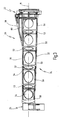
- a gear support 20 according to a preferred embodiment of the present invention is shown in FIGS Fig. 2 and 3 shown.
- the gear support 20 has an upper side member 30 in the form of an elongate plate and a lower side member 32 in the form of an elongated plate.
- the upper side rail 30 and the lower side rail 32 are provided on opposite sides of the longitudinal axis 15 and in the direction transverse to the longitudinal axis 15 aligned approximately parallel to each other. In the direction of the longitudinal axis 15, the longitudinal members 30, 32 are also aligned parallel to each other, but can also be arranged at an angle to each other (or bent).
- the longitudinal members 30, 32 are connected by means of a diaphragm 34, from which a sleeve extension 36 extends.
- a sleeve extension 36 In the sleeve extension 36, an opening 37 is formed, which is aligned with the longitudinal axis 15.
- a bearing sleeve 38 is formed on the sleeve extension 36, which forms an eyelet 40.
- a rubber bearing for supporting the bearing portion 26 can be used on the vehicle.
- the flange portion 22 has an approximately perpendicular to the longitudinal axis 15 extending flange 44, on the circumference of a plurality of mounting lugs 46 is provided.
- the mounting lugs 46 have openings (unspecified) for the passage of connecting bolts, screws, etc.
- a central opening 48 is further provided, which is also aligned with the longitudinal axis 15.
- first ribs 50 which are each aligned obliquely to the longitudinal axis 15.
- second ribs 52 which are also aligned obliquely to the longitudinal axis 15, but in the opposite direction to the first ribs 50th
- the first ribs 50 and the second ribs 52 close to each other, so that a zigzag profile is formed.
- first and second ribs 50, 52 form a sawtooth profile.
- the first and second ribs 50, 52 are formed ferrer with respective openings 54 aligned with the longitudinal axis 15.
- the openings 37, 54 and 48 serve to carry out the propeller shaft 14.
- openings 37, 54 and 48 are chosen so large that the gear support 20 does not touch the propeller shaft 14.
- a stiffening element 58 is provided at the top of the upper longitudinal member 30, .
- the stiffening element 58 extends from a central part of the support portion 24 toward an upper edge portion of the flange portion 22.
- the stiffening element 58 is also plate-shaped.
- a central stiffening rib 60 is provided, whose plane is approximately perpendicular to the planes of the upper longitudinal member 30 and the stiffening element 58th
- the gear support 20 is designed as a one-piece component and consists of light metal, in particular aluminum.
- the gear support is designed without undercuts and can be produced by die casting.
Landscapes
- Engineering & Computer Science (AREA)
- Chemical & Material Sciences (AREA)
- Combustion & Propulsion (AREA)
- Transportation (AREA)
- Mechanical Engineering (AREA)
- General Details Of Gearings (AREA)
- Motor Power Transmission Devices (AREA)
Applications Claiming Priority (2)
| Application Number | Priority Date | Filing Date | Title |
|---|---|---|---|
| DE10325381A DE10325381B8 (de) | 2003-05-30 | 2003-05-30 | Getriebestütze zur Lagerung eines Getriebes und Getriebe mit derartiger Getriebestütze |
| PCT/EP2004/005372 WO2004106098A1 (de) | 2003-05-30 | 2004-05-19 | Getriebestütze zur lagerung eines getriebes und getriebe mit derartiger getriebestütze |
Publications (2)
| Publication Number | Publication Date |
|---|---|
| EP1631471A1 EP1631471A1 (de) | 2006-03-08 |
| EP1631471B1 true EP1631471B1 (de) | 2014-06-04 |
Family
ID=33482534
Family Applications (1)
| Application Number | Title | Priority Date | Filing Date |
|---|---|---|---|
| EP04733773.8A Expired - Lifetime EP1631471B1 (de) | 2003-05-30 | 2004-05-19 | Getriebestütze zur lagerung eines getriebes und getriebe mit derartiger getriebestütze |
Country Status (6)
| Country | Link |
|---|---|
| US (1) | US7337871B2 (zh) |
| EP (1) | EP1631471B1 (zh) |
| JP (1) | JP4621207B2 (zh) |
| CN (1) | CN100374317C (zh) |
| DE (1) | DE10325381B8 (zh) |
| WO (1) | WO2004106098A1 (zh) |
Families Citing this family (4)
| Publication number | Priority date | Publication date | Assignee | Title |
|---|---|---|---|---|
| JP2007145110A (ja) * | 2005-11-25 | 2007-06-14 | Daikyoo Nishikawa Kk | フレーム構造体及び自動車のパワーユニット支持構造 |
| DE102006041094B4 (de) * | 2006-09-01 | 2015-04-02 | Audi Ag | Lagervorrichtung zur Lagerung einer Fahrzeugkomponente an einer Karosserie eines Fahrzeugs |
| JP2010001000A (ja) * | 2008-06-23 | 2010-01-07 | Hiroshi Kitamura | ソフトベアリング車輪 |
| JP2010254263A (ja) * | 2009-04-27 | 2010-11-11 | Hiroshi Kitamura | ソフトベアリング車輪 |
Family Cites Families (23)
| Publication number | Priority date | Publication date | Assignee | Title |
|---|---|---|---|---|
| DE1530516A1 (de) * | 1961-08-16 | 1969-10-02 | Daimler Benz Ag | Aufhaengung,insbesondere elastische Aufhaengung eines Achsgetriebegehaeuses fuer Kraftfahrzeuge |
| US3940162A (en) * | 1974-12-13 | 1976-02-24 | United States Steel Corporation | Structural member |
| DE2824241B2 (de) * | 1978-06-02 | 1980-10-02 | Ford-Werke Ag, 5000 Koeln | Trieb- und Fahrwerksanordnung für Kraftfahrzeuge |
| DE2838574C3 (de) * | 1978-09-05 | 1981-02-26 | Dr.Ing.H.C. F. Porsche Ag, 7000 Stuttgart | Antriebsaggregat für ein Kraftfahrzeug |
| US4386792A (en) * | 1978-10-04 | 1983-06-07 | Ford Motor Company | Fabricated load support structural member |
| DE3044288A1 (de) * | 1980-11-25 | 1982-06-24 | Dr.Ing.H.C. F. Porsche Ag, 7000 Stuttgart | Triebwerksaggregat fuer ein kraftfahrzeug |
| DE3442584A1 (de) * | 1984-11-22 | 1986-05-28 | Daimler-Benz Ag, 7000 Stuttgart | Aufhaengung eines achsgetriebegehaeuses fuer kraftfahrzeuge |
| DE8521933U1 (de) * | 1985-07-30 | 1986-10-30 | Adam Opel AG, 6090 Rüsselsheim | Triebwerksaufhängung |
| JPS62112669U (zh) * | 1986-01-08 | 1987-07-17 | ||
| JPS63269721A (ja) * | 1987-04-24 | 1988-11-08 | Mazda Motor Corp | 車両のパワ−プラントフレ−ム構造 |
| US5267623A (en) * | 1991-03-27 | 1993-12-07 | Mazda Motor Corporation | Mounting structure for a power unit of an automobile |
| DE4129538C2 (de) * | 1991-09-05 | 1993-11-18 | Porsche Ag | Fahrschemel für ein Kraftfahrzeug |
| DE4220629A1 (de) * | 1992-06-24 | 1993-04-08 | Daimler Benz Ag | Lagerung des gehaeuses eines hinterachsgetriebes eines kraftfahrzeuges |
| JPH08258738A (ja) * | 1995-03-24 | 1996-10-08 | Mitsubishi Motors Corp | 車台構造 |
| DE19613895A1 (de) * | 1996-04-06 | 1997-10-09 | Bayerische Motoren Werke Ag | Aufhängung eines KFZ-Achsgetriebes |
| US5741026A (en) * | 1996-05-31 | 1998-04-21 | Dana Corporation | Connecting and supporting structure for vehicle frame assembly |
| DE19624002C2 (de) * | 1996-06-15 | 1998-08-20 | Daimler Benz Ag | Mehrpunktlagerung eines Achsgetriebes |
| DE19623936C1 (de) * | 1996-06-15 | 1997-09-04 | Daimler Benz Ag | Lagerung eines Achsgetriebegehäuses eines Kraftfahrzeuges |
| US6273208B1 (en) * | 1998-10-15 | 2001-08-14 | Darrel R. Sand | Variable displacement vehicle engine and solid torque tube drive train |
| JP4320879B2 (ja) * | 1999-11-29 | 2009-08-26 | マツダ株式会社 | 車両のパワープラントフレーム構造 |
| DE10020079C1 (de) * | 2000-04-22 | 2001-10-31 | Getrag Getriebe Zahnrad | Achsgetriebe für ein Kraftfahrzeug |
| DE10146592C1 (de) * | 2001-09-21 | 2002-08-29 | Daimler Chrysler Ag | Hinterachsträger eines Kraftfahrzeuges |
| US20050140131A1 (en) * | 2003-12-31 | 2005-06-30 | Smith D. W. | Motor vehicle frame rail strengthening system |
-
2003
- 2003-05-30 DE DE10325381A patent/DE10325381B8/de not_active Expired - Lifetime
-
2004
- 2004-05-19 EP EP04733773.8A patent/EP1631471B1/de not_active Expired - Lifetime
- 2004-05-19 WO PCT/EP2004/005372 patent/WO2004106098A1/de active Application Filing
- 2004-05-19 JP JP2006529869A patent/JP4621207B2/ja not_active Expired - Fee Related
- 2004-05-19 CN CNB2004800150658A patent/CN100374317C/zh not_active Expired - Lifetime
-
2005
- 2005-11-29 US US11/289,765 patent/US7337871B2/en not_active Expired - Lifetime
Also Published As
| Publication number | Publication date |
|---|---|
| US7337871B2 (en) | 2008-03-04 |
| DE10325381B8 (de) | 2005-05-25 |
| JP4621207B2 (ja) | 2011-01-26 |
| WO2004106098A1 (de) | 2004-12-09 |
| CN100374317C (zh) | 2008-03-12 |
| CN1798664A (zh) | 2006-07-05 |
| JP2007531651A (ja) | 2007-11-08 |
| US20060157293A1 (en) | 2006-07-20 |
| EP1631471A1 (de) | 2006-03-08 |
| DE10325381B3 (de) | 2005-02-17 |
Similar Documents
| Publication | Publication Date | Title |
|---|---|---|
| EP0409944B1 (de) | Wischeranlage | |
| EP1712451B1 (de) | Als Fahrschemel ausgebildeter Hilfsrahmen für Kraftfahrzeuge | |
| DE3027806C2 (de) | Triebachse für Omnibusse | |
| DE102008036824B4 (de) | Querträger für ein Kraftfahrzeug | |
| DE202006004613U1 (de) | Antriebsvorrichtung für eine Verstelleinrichtung in Kraftfahrzeugen sowie Sitzverstelleinrichtung | |
| DE102010020304A1 (de) | Hilfsträger | |
| DE102006033606B4 (de) | Anordnung zur Befestigung einer Lenksäule eines Kraftfahrzeuges | |
| EP2038164B1 (de) | Abstützelement für einen cockpitträger | |
| DE3147298A1 (de) | "antriebsaggregat" | |
| DE102004050435A1 (de) | Stoßfängersystem für Kraftfahrzeug | |
| EP2030869B1 (de) | Träger als Längs- bzw. Querträger in einem Kraftfahrzeug | |
| EP1631471B1 (de) | Getriebestütze zur lagerung eines getriebes und getriebe mit derartiger getriebestütze | |
| DE102010014513A1 (de) | Verbindungsanordnung von wenigstens zwei Strukturbauteilen für einen Kraftwagen sowie Verfahren zu deren Herstellung | |
| DE102009047218A1 (de) | Antriebseinheit und Scheibenwischerantrieb mit einer Antriebseinheit | |
| DE102007061209B4 (de) | Seitentür für einen Kraftwagen | |
| DE102018108664A1 (de) | Planetenträger mit schalenförmigen Verbindungselementen | |
| EP1544085A2 (de) | Querträger eines Fahrzeugs, insbesondere Hybridquerträger | |
| DE3831480C2 (zh) | ||
| EP1670672A1 (de) | Aggregatbefestigungselement eines kraftfahrzeugs | |
| DE4002791C2 (de) | Antriebsanlage für ein Fahrzeug, insbesondere für ein Vollkettenfahrzeug | |
| DE102008036176A1 (de) | Karosserie für ein Kraftfahrzeug | |
| DE102009050470B4 (de) | Verfahren zum Bauen eines Kraftwagens | |
| AT505344B1 (de) | Lagerung eines vorderachsgetriebes bei einem kraftfahrzeug | |
| DE102009031776A1 (de) | Kraftfahrzeugrahmenstruktur | |
| DE102013210235A1 (de) | Drehmomentstütze für ein Schienenfahrzeug |
Legal Events
| Date | Code | Title | Description |
|---|---|---|---|
| PUAI | Public reference made under article 153(3) epc to a published international application that has entered the european phase |
Free format text: ORIGINAL CODE: 0009012 |
|
| 17P | Request for examination filed |
Effective date: 20051220 |
|
| AK | Designated contracting states |
Kind code of ref document: A1 Designated state(s): DE FR IT |
|
| DAX | Request for extension of the european patent (deleted) | ||
| RBV | Designated contracting states (corrected) |
Designated state(s): DE FR IT |
|
| 17Q | First examination report despatched |
Effective date: 20080407 |
|
| RAP1 | Party data changed (applicant data changed or rights of an application transferred) |
Owner name: DR. ING. H.C. F. PORSCHE AKTIENGESELLSCHAFT Owner name: GETRAG GETRIEBE- UND ZAHNRADFABRIK HERMANN HAGENME |
|
| RAP1 | Party data changed (applicant data changed or rights of an application transferred) |
Owner name: GETRAG GETRIEBE- UND ZAHNRADFABRIK HERMANN HAGENME Owner name: DR. ING. H.C. F. PORSCHE AKTIENGESELLSCHAFT |
|
| RAP1 | Party data changed (applicant data changed or rights of an application transferred) |
Owner name: DR. ING. H.C. F. PORSCHE AG Owner name: GETRAG GETRIEBE- UND ZAHNRADFABRIK HERMANN HAGENME |
|
| GRAP | Despatch of communication of intention to grant a patent |
Free format text: ORIGINAL CODE: EPIDOSNIGR1 |
|
| INTG | Intention to grant announced |
Effective date: 20131206 |
|
| GRAS | Grant fee paid |
Free format text: ORIGINAL CODE: EPIDOSNIGR3 |
|
| GRAA | (expected) grant |
Free format text: ORIGINAL CODE: 0009210 |
|
| AK | Designated contracting states |
Kind code of ref document: B1 Designated state(s): DE FR IT |
|
| REG | Reference to a national code |
Ref country code: DE Ref legal event code: R096 Ref document number: 502004014632 Country of ref document: DE Effective date: 20140717 |
|
| REG | Reference to a national code |
Ref country code: DE Ref legal event code: R097 Ref document number: 502004014632 Country of ref document: DE |
|
| PLBE | No opposition filed within time limit |
Free format text: ORIGINAL CODE: 0009261 |
|
| STAA | Information on the status of an ep patent application or granted ep patent |
Free format text: STATUS: NO OPPOSITION FILED WITHIN TIME LIMIT |
|
| 26N | No opposition filed |
Effective date: 20150305 |
|
| REG | Reference to a national code |
Ref country code: DE Ref legal event code: R097 Ref document number: 502004014632 Country of ref document: DE Effective date: 20150305 |
|
| REG | Reference to a national code |
Ref country code: FR Ref legal event code: PLFP Year of fee payment: 13 |
|
| REG | Reference to a national code |
Ref country code: FR Ref legal event code: PLFP Year of fee payment: 14 |
|
| REG | Reference to a national code |
Ref country code: FR Ref legal event code: PLFP Year of fee payment: 15 |
|
| REG | Reference to a national code |
Ref country code: DE Ref legal event code: R082 Ref document number: 502004014632 Country of ref document: DE Representative=s name: WITTE, WELLER & PARTNER PATENTANWAELTE MBB, DE Ref country code: DE Ref legal event code: R081 Ref document number: 502004014632 Country of ref document: DE Owner name: MAGNA PT B.V. & CO. KG, DE Free format text: FORMER OWNERS: DR. ING. H.C. F. PORSCHE AKTIENGESELLSCHAFT, 70435 STUTTGART, DE; GETRAG GETRIEBE- UND ZAHNRADFABRIK HERMANN HAGENMEYER GMBH & CIE KG, 74199 UNTERGRUPPENBACH, DE Ref country code: DE Ref legal event code: R081 Ref document number: 502004014632 Country of ref document: DE Owner name: DR. ING. H.C. F. PORSCHE AKTIENGESELLSCHAFT, DE Free format text: FORMER OWNERS: DR. ING. H.C. F. PORSCHE AKTIENGESELLSCHAFT, 70435 STUTTGART, DE; GETRAG GETRIEBE- UND ZAHNRADFABRIK HERMANN HAGENMEYER GMBH & CIE KG, 74199 UNTERGRUPPENBACH, DE |
|
| P01 | Opt-out of the competence of the unified patent court (upc) registered |
Effective date: 20230526 |
|
| PGFP | Annual fee paid to national office [announced via postgrant information from national office to epo] |
Ref country code: IT Payment date: 20230526 Year of fee payment: 20 Ref country code: FR Payment date: 20230525 Year of fee payment: 20 Ref country code: DE Payment date: 20230620 Year of fee payment: 20 |
|
| REG | Reference to a national code |
Ref country code: DE Ref legal event code: R071 Ref document number: 502004014632 Country of ref document: DE |