EP1631172B1 - Vorrichtung zur halterung einer von tragarmen gestützten querstange - Google Patents
Vorrichtung zur halterung einer von tragarmen gestützten querstange Download PDFInfo
- Publication number
- EP1631172B1 EP1631172B1 EP04734801A EP04734801A EP1631172B1 EP 1631172 B1 EP1631172 B1 EP 1631172B1 EP 04734801 A EP04734801 A EP 04734801A EP 04734801 A EP04734801 A EP 04734801A EP 1631172 B1 EP1631172 B1 EP 1631172B1
- Authority
- EP
- European Patent Office
- Prior art keywords
- transverse rod
- insert
- adaptor
- crossbar
- supporting
- Prior art date
- Legal status (The legal status is an assumption and is not a legal conclusion. Google has not performed a legal analysis and makes no representation as to the accuracy of the status listed.)
- Expired - Lifetime
Links
- 239000013013 elastic material Substances 0.000 claims abstract description 4
- 239000000463 material Substances 0.000 claims description 4
- 229920000515 polycarbonate Polymers 0.000 claims description 3
- 239000004417 polycarbonate Substances 0.000 claims description 3
- 238000004519 manufacturing process Methods 0.000 description 3
- 210000001331 nose Anatomy 0.000 description 3
- 238000010276 construction Methods 0.000 description 2
- 238000003466 welding Methods 0.000 description 2
- 229910000639 Spring steel Inorganic materials 0.000 description 1
- 239000000969 carrier Substances 0.000 description 1
- 238000006073 displacement reaction Methods 0.000 description 1
- 238000003780 insertion Methods 0.000 description 1
- 230000037431 insertion Effects 0.000 description 1
- 238000009434 installation Methods 0.000 description 1
- 238000012423 maintenance Methods 0.000 description 1
- 238000003032 molecular docking Methods 0.000 description 1
- 230000000284 resting effect Effects 0.000 description 1
- 238000007493 shaping process Methods 0.000 description 1
- 239000000725 suspension Substances 0.000 description 1
Images


Classifications
-
- A—HUMAN NECESSITIES
- A47—FURNITURE; DOMESTIC ARTICLES OR APPLIANCES; COFFEE MILLS; SPICE MILLS; SUCTION CLEANERS IN GENERAL
- A47F—SPECIAL FURNITURE, FITTINGS, OR ACCESSORIES FOR SHOPS, STOREHOUSES, BARS, RESTAURANTS OR THE LIKE; PAYING COUNTERS
- A47F5/00—Show stands, hangers, or shelves characterised by their constructional features
- A47F5/08—Show stands, hangers, or shelves characterised by their constructional features secured to the wall, ceiling, or the like; Wall-bracket display devices
-
- A—HUMAN NECESSITIES
- A47—FURNITURE; DOMESTIC ARTICLES OR APPLIANCES; COFFEE MILLS; SPICE MILLS; SUCTION CLEANERS IN GENERAL
- A47F—SPECIAL FURNITURE, FITTINGS, OR ACCESSORIES FOR SHOPS, STOREHOUSES, BARS, RESTAURANTS OR THE LIKE; PAYING COUNTERS
- A47F7/00—Show stands, hangers, or shelves, adapted for particular articles or materials
- A47F7/19—Show stands, hangers, or shelves, adapted for particular articles or materials for garments
- A47F7/24—Clothes racks
Definitions
- the invention relates to a device for supporting a supported by at least two support arms crossbar, which is intended for hanging of support brackets, in particular hangers.
- the brackets can be hung in differently configured brackets, such as profiled horizontal or vertical rails, grid elements or punctiform sockets.
- the mounting brackets are intended for hanging objects, in particular garments, and can be moved freely on the crossbar.
- Such devices are typically used on presentation walls or permanently installed or movable goods stands of the shop area.
- the eyelet which includes the crossbar, a lateral boundary.
- the US 3,322,288 has a device for releasably supporting a supported by at least two support arms crossbar to the object.
- the support arms are detachably mounted with their first end in a support structure.
- the crossbar is designed to hang carrying hangers suspended on garments, which can be moved freely on the crossbar.
- connecting means are arranged with an opening for receiving the cross section of the crossbar, wherein the crossbar is clamped under.
- the connecting means consists of an adapter attached to the second end of the support arm and an insert to be placed on the adapter, which provides elastic clamping forces.
- the insert extends radially beyond half of the circumference of the cross bar and has an opening which extends over the upper portion and initially expanded upon insertion of the crossbar and then narrowed again, whereby an inserted crossbar is clamped under.
- the adapter has a relatively large shell segment on which the insert is mounted in the form of a larger half-shell made of spring steel. The engagement and release of the crossbar from the clamping bracket should require considerable effort and cause noise. Furthermore, the device is material-consuming and has a rough appearance.
- the invention has for its object to simplify the connecting means for releasably securing an inserted crossbar to the support arms.
- Requirements here are a complicate handling when installing a crossbar, the safe and rotationally stable locking an inserted crossbar, the fulfillment of aesthetic aspects and finally a low material and manufacturing costs to maintain low production and assembly costs in mass production.
- the device for differently configured support arms and these receiving brackets such as profiled horizontal or vertical rails, carriers with grids or pointy sockets, can be realized.
- the support arms should have a connection piece, which can be releasably fixed in the brackets.
- the device relates to a releasable support of a supported by at least two support arms crossbar.
- the support arms are releasably fixed with their first end or fixed in a support structure.
- the crossbar is intended for hanging straps, in particular hangers, the straps for hanging objects, primarily garments, serve and can be moved freely on the crossbar.
- connecting means for receiving the crossbar are arranged at the projecting into the space second end of each support arm.
- the connecting means is fork-shaped with an opening for receiving the cross section of the crossbar, wherein the crossbar is clamped partially included.
- the connecting means initially consists of a attached to the second end of the support arm or e.g. by welding, cutting or non-cutting shaping molded adapter.
- the connecting means further comprises an insert to be placed on the adapter which provides elastic clamping forces and is made of elastic material - e.g. Polycarbonate - and / or provided with spring elements
- the support arm can e.g. consist of round, tubular or flat material in cross-section.
- the insert has an over the upper portion extending opening with a span, which initially widens when introducing the crossbar and then narrowed again, whereby an inserted crossbar is clamped under. The insert extends radially beyond half the circumference of the cross bar.
- the adapter consists of a base body and initially has an arcuate cutout to the support arm transversal passage direction, which lies axially to salaried crossbar. On both sides of the cut extends a respective neckline surrounding, upwardly extending bracket. At the free upper ends of the bracket depending on a continuing nose is provided, the noses are directed towards each other and into the cutout.
- the insert is a basically half shell-shaped body. This has two projecting into the room, leaving an opening between them.
- the insert has a curved inner surface and a curved outer surface.
- a circumferentially circumferential groove on the outer surface, which expires at a distance from the ends, is intended for partial reception of the adapter. At the outlet of the groove is ever a breakthrough for engagement of the lugs.
- the lugs on the adapter are arranged in principle at a distance corresponding to the diameter of the crossbar.
- a groove is formed, while in the groove of the insert extends a raised web, which comes to rest in the groove in the adapter when mounted insert.
- the support structure consists e.g. from a panel wall fixedly mounted in a building or a freestanding rack with brackets attached thereto.
- Preferred brackets are profiled horizontal or vertical rails or pointy sockets into consideration.
- the support arms have at the first end a fitting which is intended to be releasably secured in the brackets.
- For the crossbars is preferably a circular cross section into consideration. However, it could also be a roundish cross-sectional shape, which tapers above a maximum width.
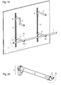
- two mutually parallel spaced vertical rails 2 are attached on a panel wall 1, which could be firmly fixed to a building part.
- These vertical rails 2 are each equipped with two support arms 3 in an upper first level and a lower second level.
- a support arm 3 of the upper level is stepped, while the adjacent support arm 3 extends straight into the room; both are empty.
- both support arms extend straight and support the horizontally launched crossbar 7 of round cross section in each case in an adapter 5 and an insert 6, which are arranged at the front of the support arms 3 .
- the adapter 5 with the insert 6 together form a releasable connecting means 5,6.
- the trapped therein crossbar 7 bridges the gap between two support arms 3 and extends to both sides beyond this.
- the support arms 3 are mounted with their fittings 4 in the vertical rails 2 .
- the panel wall 1 and the vertical rails mounted thereon, the support structure 2 form 1.2 for the inventive device.
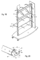
- the support structure 1, 2 is formed by a movable frame 1 and vertical rails 2 pointing upwards.
- the vertical rails 2 are arranged in pairs, so that they can be populated on both sides.
- hinged support arms 3 again hold a clamped on adapters 5 and 6 inserts resting crossbar . 7
- FIGS. 2A and 2B are identical to FIGS. 2A and 2B.
- the first embodiment support arm 3 has at its tube piece a first end 31 and a second end 30 , wherein at the first end 31, the connector 4 is arranged, while at the second end 30 of the adapter 5 is, for example, by welding, cutting or non-cutting Forming is recognized or molded.
- the adapter 5 consists of an attached, in principle flat base body 50, with an upwardly open, arcuate cutout 51 to the support arm 3 transverse passage R.
- On both sides of the cut 51 runs upwardly extending bracket 54 , at the free upper ends lugs 52 are provided which face each other and in the cutout 51 .
- the lugs 52 leave between them the distance d, which corresponds to the diameter of the crossbar 7 .
- the groove 53 is present.
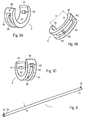
- the insert 6 to be placed on the adapter 5 is made of elastic material, eg polycarbonate, and in principle has the shape of a half shell extending beyond 180 ° with an overhead opening of the span a between the two ends 60, 61 projecting into the space . Furthermore, a curved inner surface 63 and a curved outer surface 64 are provided on the insert, wherein a circular circumferential groove 65 is provided on the outer surface and terminates at a distance from the ends 60, 61 . In each case a breakthrough 62 is present at the outlet of the groove 65 . In the groove 65 a raised web 66 runs.
- elastic material eg polycarbonate
- the crossbar 7 is formed by a straight pipe section with the diameter d , which has a first end 70 and a second end 71 . At both ends 70,71 upstanding boundary elements 72 are provided to prevent fall on the crossbar 7 attached mounting bracket .
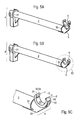
- the insert 6 is plugged onto the adapter 5 for complete construction of the connecting means.
- the insert 6 comes to lie in the cutout 51 of the adapter 5 , the latter being partially received in the groove 65 of the insert 6 .
- the lugs 52 of the adapter 5 engage through the apertures 62 of the insert 6 , and the web 66 rests in the groove 53 in the adapter.
- the upwardly projecting ends 60,61 of the insert 6 leave between them an opening with the span a for receiving the crossbar . 7
- a support arm 3 second embodiment instead of a pipe piece having a strut made of flat material, at the second end 30 of the adapter 5 is formed, which identical contours to the adapter 5 on the support arm 3 according to the first embodiment FIG. 2A having.
- a connecting piece 4 for mounting in a holder 2, for example, a horizontal rail is provided.
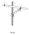
- This series of figures illustrates the introduction of the transverse rod 7 in the formed of adapter 5 and insert 6 connecting means with the upwardly directed fork-shaped opening for the clamping, the partial enclosure of the cross section of the cross bar 7.
- the cross bar 7 Due to the elasticity of the insert 6 , the cross bar 7 is secured in the upward direction and can only be removed from the connecting means 5,6 when a pull-out force is applied to overcome the clamping action of the insert 6 .
- the rotation of the introduced crossbar 7 is causes the tabs 52 of the adapter 5 come to lie clamped on the outer circumference of the crossbar 7 .
- An inserted crossbar 7 is held at least by two support arms 3 and may extend depending on the lateral load with their ends 70,71 in a corresponding width on the connecting means 5,6 addition.
Landscapes
- Supports Or Holders For Household Use (AREA)
- Lock And Its Accessories (AREA)
- Forklifts And Lifting Vehicles (AREA)
- Holders For Apparel And Elements Relating To Apparel (AREA)
- Clamps And Clips (AREA)
Applications Claiming Priority (2)
| Application Number | Priority Date | Filing Date | Title |
|---|---|---|---|
| DE20309049U DE20309049U1 (de) | 2003-06-11 | 2003-06-11 | Vorrichtung zur Halterung einer von Tragarmen gestützten Querstange |
| PCT/CH2004/000319 WO2004107930A1 (de) | 2003-06-11 | 2004-05-26 | Vorrichtung zur halterung einer von tragarmen gestützten querstange |
Publications (2)
| Publication Number | Publication Date |
|---|---|
| EP1631172A1 EP1631172A1 (de) | 2006-03-08 |
| EP1631172B1 true EP1631172B1 (de) | 2010-07-14 |
Family
ID=27763266
Family Applications (1)
| Application Number | Title | Priority Date | Filing Date |
|---|---|---|---|
| EP04734801A Expired - Lifetime EP1631172B1 (de) | 2003-06-11 | 2004-05-26 | Vorrichtung zur halterung einer von tragarmen gestützten querstange |
Country Status (6)
| Country | Link |
|---|---|
| US (1) | US20060118505A1 (es) |
| EP (1) | EP1631172B1 (es) |
| AT (1) | ATE473659T1 (es) |
| DE (2) | DE20309049U1 (es) |
| ES (1) | ES2347148T3 (es) |
| WO (1) | WO2004107930A1 (es) |
Families Citing this family (13)
| Publication number | Priority date | Publication date | Assignee | Title |
|---|---|---|---|---|
| DE20307228U1 (de) | 2003-05-08 | 2003-07-10 | Klencke, Hans-Hermann, 21255 Tostedt | Präsentationsvorrichtung für zu begutachtende Gegenstände |
| US7665619B2 (en) * | 2006-07-27 | 2010-02-23 | Ingenious Designs Llc | Modular shelf system |
| US20080023428A1 (en) * | 2006-07-27 | 2008-01-31 | Joy Mangano | Modular shelf system |
| US20130068710A1 (en) * | 2011-09-16 | 2013-03-21 | Gary Cearns | Rack For Horizontal Storage |
| US9364104B1 (en) | 2014-12-11 | 2016-06-14 | Opto International, Inc. | Collapsing clothing display fixture |
| CA2943123A1 (en) * | 2016-09-27 | 2018-03-27 | Robert Winikoff | A display rack |
| US9743761B1 (en) | 2016-11-01 | 2017-08-29 | Steven J. O'Day | Ergonomic locker system |
| US12096870B2 (en) * | 2018-05-31 | 2024-09-24 | Whitmor, Inc. | Laundry valet rod |
| US10383437B1 (en) | 2018-07-18 | 2019-08-20 | Steven J. O'Day | Locker system modification kit |
| US10299615B1 (en) * | 2018-07-31 | 2019-05-28 | Stephen P. Donegan | Hanger spacer tape |
| US10952576B2 (en) * | 2018-10-17 | 2021-03-23 | Liberty Hardware Mfg. Corp. | Adjustable bathroom handrail assembly |
| USD1008705S1 (en) * | 2023-04-10 | 2023-12-26 | Xiamen Yinsa Electronic Commerce Co., Ltd. | Wall mounted coat rack |
| USD1008706S1 (en) * | 2023-04-10 | 2023-12-26 | Xiamen Yinsa Electronic Commerce Co., Ltd. | Wall mounted coat rack |
Family Cites Families (11)
| Publication number | Priority date | Publication date | Assignee | Title |
|---|---|---|---|---|
| US275481A (en) * | 1883-04-10 | Eobebt s | ||
| US531416A (en) * | 1894-12-25 | adams | ||
| US3322288A (en) * | 1966-04-25 | 1967-05-30 | Capitol Hardware Mfg Co | Clothing display rack assembly |
| US3664511A (en) * | 1970-10-02 | 1972-05-23 | Streater Ind Inc | Hangrod assembly |
| US3784023A (en) * | 1970-11-27 | 1974-01-08 | Crown Metal Mfg Co | Hang rail support structure |
| US3731817A (en) * | 1971-03-31 | 1973-05-08 | Fo Mac Enterprises Inc | Fishing rod holder |
| DE2439143A1 (de) * | 1974-08-14 | 1976-02-26 | Werner E Dahnz | Rohrstangen-halterung an konsolen |
| US4108313A (en) * | 1977-05-12 | 1978-08-22 | Bogar Jr Earl M | Vehicle mounted gun rack with mounting brackets |
| US4991723A (en) * | 1989-09-15 | 1991-02-12 | Elkins Johnny C | Adjustable universal gun rack |
| US5531416A (en) * | 1994-09-30 | 1996-07-02 | Clairson, Inc. | Continuous slide bracket |
| US6053465A (en) * | 1998-05-23 | 2000-04-25 | John Sterling Corporation | Shelf and clothes rod bracket |
-
2003
- 2003-06-11 DE DE20309049U patent/DE20309049U1/de not_active Expired - Lifetime
-
2004
- 2004-05-26 DE DE502004011401T patent/DE502004011401D1/de not_active Expired - Lifetime
- 2004-05-26 US US10/559,805 patent/US20060118505A1/en not_active Abandoned
- 2004-05-26 ES ES04734801T patent/ES2347148T3/es not_active Expired - Lifetime
- 2004-05-26 EP EP04734801A patent/EP1631172B1/de not_active Expired - Lifetime
- 2004-05-26 AT AT04734801T patent/ATE473659T1/de active
- 2004-05-26 WO PCT/CH2004/000319 patent/WO2004107930A1/de not_active Ceased
Also Published As
| Publication number | Publication date |
|---|---|
| ATE473659T1 (de) | 2010-07-15 |
| WO2004107930A1 (de) | 2004-12-16 |
| DE20309049U1 (de) | 2003-08-14 |
| US20060118505A1 (en) | 2006-06-08 |
| EP1631172A1 (de) | 2006-03-08 |
| DE502004011401D1 (de) | 2010-08-26 |
| ES2347148T3 (es) | 2010-10-26 |
Similar Documents
| Publication | Publication Date | Title |
|---|---|---|
| DE102007060030B4 (de) | Luft- oder Raumfahrzeug mit einer Vorrichtung zur Halterung von Systemen | |
| WO2003041540A1 (de) | Aufhängevorrichtung mit einer vertikal anzuordnenden profilschiene und einer darin einhängbaren konsole | |
| WO1999065367A1 (de) | Displayvorrichtung zur präsentation von waren | |
| WO2004107930A1 (de) | Vorrichtung zur halterung einer von tragarmen gestützten querstange | |
| WO2009073989A1 (de) | Aufhängevorrichtung mit einer profilierten vertikalstütze und einem daran einhängbaren primärträger | |
| EP2391244B1 (de) | Vorrichtung zur hängenden oder liegenden präsentation von artikeln | |
| CH712455B1 (de) | Adapter, Warenträger und Befestigungssystem. | |
| EP2154761A1 (de) | Kabelführung an einem Tisch | |
| WO1997026809A1 (de) | Tragstangenanordnung für die präsentation von waren | |
| EP0508300B1 (de) | Aufhängevorrichtung für eine Luftkabelgarnitur | |
| EP2587969B1 (de) | Vorrichtung zur präsentation von artikeln | |
| DE102015112039A1 (de) | Gestell für Notstrombatterien | |
| CH719491A1 (de) | Deckenabhängung und Tragsystem. | |
| DE202017000362U1 (de) | Sanitärobjekt-Haltevorrichtung | |
| DE202005006607U1 (de) | Aufhängevorrichtung zur Warenpräsentation mit einer Vertikalstütze und darin einhängbarem Tragarm | |
| EP1553347B1 (de) | Haushaltsgerät, insbesondere Gargerät | |
| DE19944232C2 (de) | Anordnung für den Einbau in einen Schrank | |
| DE202010005116U1 (de) | Aufhängevorrichtung zur Präsentation von Gegenständen | |
| EP1145675A1 (de) | Befestigungssystem für sanitäre Gebrauchsgegenstände | |
| DE4116028C2 (es) | ||
| DE29923599U1 (de) | Tragstangenanordnung für Handels- und Dienstleistungseinrichtungen | |
| EP0868872A1 (de) | Vorrichtung zur Präsentation von Waren | |
| DE20104848U1 (de) | Aufnahmevorrichtung für Dekorationen | |
| DE4006110A1 (de) | Regalsystem | |
| DE29712525U1 (de) | Tragvorrichtung, insbesondere für Regale o.dgl. |
Legal Events
| Date | Code | Title | Description |
|---|---|---|---|
| PUAI | Public reference made under article 153(3) epc to a published international application that has entered the european phase |
Free format text: ORIGINAL CODE: 0009012 |
|
| 17P | Request for examination filed |
Effective date: 20051121 |
|
| AK | Designated contracting states |
Kind code of ref document: A1 Designated state(s): AT BE BG CH CY CZ DE DK EE ES FI FR GB GR HU IE IT LI LU MC NL PL PT RO SE SI SK TR |
|
| 17Q | First examination report despatched |
Effective date: 20060720 |
|
| DAX | Request for extension of the european patent (deleted) | ||
| GRAP | Despatch of communication of intention to grant a patent |
Free format text: ORIGINAL CODE: EPIDOSNIGR1 |
|
| GRAS | Grant fee paid |
Free format text: ORIGINAL CODE: EPIDOSNIGR3 |
|
| GRAA | (expected) grant |
Free format text: ORIGINAL CODE: 0009210 |
|
| AK | Designated contracting states |
Kind code of ref document: B1 Designated state(s): AT BE BG CH CY CZ DE DK EE ES FI FR GB GR HU IE IT LI LU MC NL PL PT RO SE SI SK TR |
|
| REG | Reference to a national code |
Ref country code: GB Ref legal event code: FG4D Free format text: NOT ENGLISH |
|
| REG | Reference to a national code |
Ref country code: CH Ref legal event code: EP |
|
| REG | Reference to a national code |
Ref country code: CH Ref legal event code: NV Representative=s name: AXON PATENT GMBH |
|
| REG | Reference to a national code |
Ref country code: IE Ref legal event code: FG4D |
|
| REF | Corresponds to: |
Ref document number: 502004011401 Country of ref document: DE Date of ref document: 20100826 Kind code of ref document: P |
|
| REG | Reference to a national code |
Ref country code: ES Ref legal event code: FG2A Ref document number: 2347148 Country of ref document: ES Kind code of ref document: T3 |
|
| REG | Reference to a national code |
Ref country code: NL Ref legal event code: VDEP Effective date: 20100714 |
|
| PG25 | Lapsed in a contracting state [announced via postgrant information from national office to epo] |
Ref country code: NL Free format text: LAPSE BECAUSE OF FAILURE TO SUBMIT A TRANSLATION OF THE DESCRIPTION OR TO PAY THE FEE WITHIN THE PRESCRIBED TIME-LIMIT Effective date: 20100714 Ref country code: FI Free format text: LAPSE BECAUSE OF FAILURE TO SUBMIT A TRANSLATION OF THE DESCRIPTION OR TO PAY THE FEE WITHIN THE PRESCRIBED TIME-LIMIT Effective date: 20100714 |
|
| REG | Reference to a national code |
Ref country code: IE Ref legal event code: FD4D |
|
| PG25 | Lapsed in a contracting state [announced via postgrant information from national office to epo] |
Ref country code: PT Free format text: LAPSE BECAUSE OF FAILURE TO SUBMIT A TRANSLATION OF THE DESCRIPTION OR TO PAY THE FEE WITHIN THE PRESCRIBED TIME-LIMIT Effective date: 20101115 Ref country code: BG Free format text: LAPSE BECAUSE OF FAILURE TO SUBMIT A TRANSLATION OF THE DESCRIPTION OR TO PAY THE FEE WITHIN THE PRESCRIBED TIME-LIMIT Effective date: 20101014 Ref country code: SI Free format text: LAPSE BECAUSE OF FAILURE TO SUBMIT A TRANSLATION OF THE DESCRIPTION OR TO PAY THE FEE WITHIN THE PRESCRIBED TIME-LIMIT Effective date: 20100714 Ref country code: PL Free format text: LAPSE BECAUSE OF FAILURE TO SUBMIT A TRANSLATION OF THE DESCRIPTION OR TO PAY THE FEE WITHIN THE PRESCRIBED TIME-LIMIT Effective date: 20100714 Ref country code: CY Free format text: LAPSE BECAUSE OF FAILURE TO SUBMIT A TRANSLATION OF THE DESCRIPTION OR TO PAY THE FEE WITHIN THE PRESCRIBED TIME-LIMIT Effective date: 20100714 |
|
| PG25 | Lapsed in a contracting state [announced via postgrant information from national office to epo] |
Ref country code: GR Free format text: LAPSE BECAUSE OF FAILURE TO SUBMIT A TRANSLATION OF THE DESCRIPTION OR TO PAY THE FEE WITHIN THE PRESCRIBED TIME-LIMIT Effective date: 20101015 Ref country code: SE Free format text: LAPSE BECAUSE OF FAILURE TO SUBMIT A TRANSLATION OF THE DESCRIPTION OR TO PAY THE FEE WITHIN THE PRESCRIBED TIME-LIMIT Effective date: 20100714 |
|
| PG25 | Lapsed in a contracting state [announced via postgrant information from national office to epo] |
Ref country code: DK Free format text: LAPSE BECAUSE OF FAILURE TO SUBMIT A TRANSLATION OF THE DESCRIPTION OR TO PAY THE FEE WITHIN THE PRESCRIBED TIME-LIMIT Effective date: 20100714 Ref country code: IE Free format text: LAPSE BECAUSE OF FAILURE TO SUBMIT A TRANSLATION OF THE DESCRIPTION OR TO PAY THE FEE WITHIN THE PRESCRIBED TIME-LIMIT Effective date: 20100714 |
|
| PLBE | No opposition filed within time limit |
Free format text: ORIGINAL CODE: 0009261 |
|
| STAA | Information on the status of an ep patent application or granted ep patent |
Free format text: STATUS: NO OPPOSITION FILED WITHIN TIME LIMIT |
|
| PG25 | Lapsed in a contracting state [announced via postgrant information from national office to epo] |
Ref country code: IT Free format text: LAPSE BECAUSE OF FAILURE TO SUBMIT A TRANSLATION OF THE DESCRIPTION OR TO PAY THE FEE WITHIN THE PRESCRIBED TIME-LIMIT Effective date: 20100714 Ref country code: CZ Free format text: LAPSE BECAUSE OF FAILURE TO SUBMIT A TRANSLATION OF THE DESCRIPTION OR TO PAY THE FEE WITHIN THE PRESCRIBED TIME-LIMIT Effective date: 20100714 Ref country code: EE Free format text: LAPSE BECAUSE OF FAILURE TO SUBMIT A TRANSLATION OF THE DESCRIPTION OR TO PAY THE FEE WITHIN THE PRESCRIBED TIME-LIMIT Effective date: 20100714 Ref country code: RO Free format text: LAPSE BECAUSE OF FAILURE TO SUBMIT A TRANSLATION OF THE DESCRIPTION OR TO PAY THE FEE WITHIN THE PRESCRIBED TIME-LIMIT Effective date: 20100714 Ref country code: SK Free format text: LAPSE BECAUSE OF FAILURE TO SUBMIT A TRANSLATION OF THE DESCRIPTION OR TO PAY THE FEE WITHIN THE PRESCRIBED TIME-LIMIT Effective date: 20100714 |
|
| 26N | No opposition filed |
Effective date: 20110415 |
|
| REG | Reference to a national code |
Ref country code: DE Ref legal event code: R097 Ref document number: 502004011401 Country of ref document: DE Effective date: 20110415 |
|
| PGFP | Annual fee paid to national office [announced via postgrant information from national office to epo] |
Ref country code: CH Payment date: 20110525 Year of fee payment: 8 |
|
| BERE | Be: lapsed |
Owner name: VISPLAY INTERNATIONAL A.G. Effective date: 20110531 |
|
| PG25 | Lapsed in a contracting state [announced via postgrant information from national office to epo] |
Ref country code: MC Free format text: LAPSE BECAUSE OF NON-PAYMENT OF DUE FEES Effective date: 20110531 |
|
| GBPC | Gb: european patent ceased through non-payment of renewal fee |
Effective date: 20110526 |
|
| REG | Reference to a national code |
Ref country code: FR Ref legal event code: ST Effective date: 20120131 |
|
| REG | Reference to a national code |
Ref country code: DE Ref legal event code: R119 Ref document number: 502004011401 Country of ref document: DE Effective date: 20111201 |
|
| PG25 | Lapsed in a contracting state [announced via postgrant information from national office to epo] |
Ref country code: BE Free format text: LAPSE BECAUSE OF NON-PAYMENT OF DUE FEES Effective date: 20110531 |
|
| PG25 | Lapsed in a contracting state [announced via postgrant information from national office to epo] |
Ref country code: FR Free format text: LAPSE BECAUSE OF NON-PAYMENT OF DUE FEES Effective date: 20110531 |
|
| PG25 | Lapsed in a contracting state [announced via postgrant information from national office to epo] |
Ref country code: GB Free format text: LAPSE BECAUSE OF NON-PAYMENT OF DUE FEES Effective date: 20110526 |
|
| REG | Reference to a national code |
Ref country code: AT Ref legal event code: MM01 Ref document number: 473659 Country of ref document: AT Kind code of ref document: T Effective date: 20110526 |
|
| REG | Reference to a national code |
Ref country code: CH Ref legal event code: PL |
|
| PG25 | Lapsed in a contracting state [announced via postgrant information from national office to epo] |
Ref country code: CH Free format text: LAPSE BECAUSE OF NON-PAYMENT OF DUE FEES Effective date: 20120531 Ref country code: AT Free format text: LAPSE BECAUSE OF NON-PAYMENT OF DUE FEES Effective date: 20110526 Ref country code: LI Free format text: LAPSE BECAUSE OF NON-PAYMENT OF DUE FEES Effective date: 20120531 |
|
| REG | Reference to a national code |
Ref country code: ES Ref legal event code: FD2A Effective date: 20130405 |
|
| PG25 | Lapsed in a contracting state [announced via postgrant information from national office to epo] |
Ref country code: ES Free format text: LAPSE BECAUSE OF NON-PAYMENT OF DUE FEES Effective date: 20110527 |
|
| PG25 | Lapsed in a contracting state [announced via postgrant information from national office to epo] |
Ref country code: LU Free format text: LAPSE BECAUSE OF NON-PAYMENT OF DUE FEES Effective date: 20110526 |
|
| PG25 | Lapsed in a contracting state [announced via postgrant information from national office to epo] |
Ref country code: DE Free format text: LAPSE BECAUSE OF NON-PAYMENT OF DUE FEES Effective date: 20111201 |
|
| PG25 | Lapsed in a contracting state [announced via postgrant information from national office to epo] |
Ref country code: TR Free format text: LAPSE BECAUSE OF FAILURE TO SUBMIT A TRANSLATION OF THE DESCRIPTION OR TO PAY THE FEE WITHIN THE PRESCRIBED TIME-LIMIT Effective date: 20100714 |
|
| PG25 | Lapsed in a contracting state [announced via postgrant information from national office to epo] |
Ref country code: HU Free format text: LAPSE BECAUSE OF FAILURE TO SUBMIT A TRANSLATION OF THE DESCRIPTION OR TO PAY THE FEE WITHIN THE PRESCRIBED TIME-LIMIT Effective date: 20100714 |