EP1626424A2 - Eingabevorrichtung mit mehreren Kontakten - Google Patents
Eingabevorrichtung mit mehreren Kontakten Download PDFInfo
- Publication number
- EP1626424A2 EP1626424A2 EP05254938A EP05254938A EP1626424A2 EP 1626424 A2 EP1626424 A2 EP 1626424A2 EP 05254938 A EP05254938 A EP 05254938A EP 05254938 A EP05254938 A EP 05254938A EP 1626424 A2 EP1626424 A2 EP 1626424A2
- Authority
- EP
- European Patent Office
- Prior art keywords
- operating member
- drive unit
- central switch
- input device
- contact input
- Prior art date
- Legal status (The legal status is an assumption and is not a legal conclusion. Google has not performed a legal analysis and makes no representation as to the accuracy of the status listed.)
- Granted
Links
- 230000002093 peripheral effect Effects 0.000 claims abstract description 64
- 230000006378 damage Effects 0.000 claims abstract description 14
- 230000007935 neutral effect Effects 0.000 claims description 26
- 238000003780 insertion Methods 0.000 description 10
- 230000037431 insertion Effects 0.000 description 10
- 239000011347 resin Substances 0.000 description 8
- 229920005989 resin Polymers 0.000 description 8
- 239000002184 metal Substances 0.000 description 7
- 239000002131 composite material Substances 0.000 description 6
- 230000000717 retained effect Effects 0.000 description 5
- 230000014759 maintenance of location Effects 0.000 description 4
- 238000003466 welding Methods 0.000 description 3
- 230000007547 defect Effects 0.000 description 2
- 230000000149 penetrating effect Effects 0.000 description 2
- 230000006835 compression Effects 0.000 description 1
- 238000007906 compression Methods 0.000 description 1
- 230000003247 decreasing effect Effects 0.000 description 1
- 230000000994 depressogenic effect Effects 0.000 description 1
- 238000000034 method Methods 0.000 description 1
- 238000012986 modification Methods 0.000 description 1
- 230000004048 modification Effects 0.000 description 1
- 210000002105 tongue Anatomy 0.000 description 1
Images






Classifications
-
- G—PHYSICS
- G05—CONTROLLING; REGULATING
- G05G—CONTROL DEVICES OR SYSTEMS INSOFAR AS CHARACTERISED BY MECHANICAL FEATURES ONLY
- G05G9/00—Manually-actuated control mechanisms provided with one single controlling member co-operating with two or more controlled members, e.g. selectively, simultaneously
- G05G9/02—Manually-actuated control mechanisms provided with one single controlling member co-operating with two or more controlled members, e.g. selectively, simultaneously the controlling member being movable in different independent ways, movement in each individual way actuating one controlled member only
- G05G9/04—Manually-actuated control mechanisms provided with one single controlling member co-operating with two or more controlled members, e.g. selectively, simultaneously the controlling member being movable in different independent ways, movement in each individual way actuating one controlled member only in which movement in two or more ways can occur simultaneously
- G05G9/047—Manually-actuated control mechanisms provided with one single controlling member co-operating with two or more controlled members, e.g. selectively, simultaneously the controlling member being movable in different independent ways, movement in each individual way actuating one controlled member only in which movement in two or more ways can occur simultaneously the controlling member being movable by hand about orthogonal axes, e.g. joysticks
- G05G9/04785—Manually-actuated control mechanisms provided with one single controlling member co-operating with two or more controlled members, e.g. selectively, simultaneously the controlling member being movable in different independent ways, movement in each individual way actuating one controlled member only in which movement in two or more ways can occur simultaneously the controlling member being movable by hand about orthogonal axes, e.g. joysticks the controlling member being the operating part of a switch arrangement
- G05G9/04788—Manually-actuated control mechanisms provided with one single controlling member co-operating with two or more controlled members, e.g. selectively, simultaneously the controlling member being movable in different independent ways, movement in each individual way actuating one controlled member only in which movement in two or more ways can occur simultaneously the controlling member being movable by hand about orthogonal axes, e.g. joysticks the controlling member being the operating part of a switch arrangement comprising additional control elements
- G05G9/04796—Manually-actuated control mechanisms provided with one single controlling member co-operating with two or more controlled members, e.g. selectively, simultaneously the controlling member being movable in different independent ways, movement in each individual way actuating one controlled member only in which movement in two or more ways can occur simultaneously the controlling member being movable by hand about orthogonal axes, e.g. joysticks the controlling member being the operating part of a switch arrangement comprising additional control elements for rectilinear control along the axis of the controlling member
-
- H—ELECTRICITY
- H01—ELECTRIC ELEMENTS
- H01H—ELECTRIC SWITCHES; RELAYS; SELECTORS; EMERGENCY PROTECTIVE DEVICES
- H01H25/00—Switches with compound movement of handle or other operating part
- H01H25/04—Operating part movable angularly in more than one plane, e.g. joystick
-
- H—ELECTRICITY
- H01—ELECTRIC ELEMENTS
- H01H—ELECTRIC SWITCHES; RELAYS; SELECTORS; EMERGENCY PROTECTIVE DEVICES
- H01H25/00—Switches with compound movement of handle or other operating part
- H01H25/04—Operating part movable angularly in more than one plane, e.g. joystick
- H01H25/041—Operating part movable angularly in more than one plane, e.g. joystick having a generally flat operating member depressible at different locations to operate different controls
- H01H2025/046—Operating part movable angularly in more than one plane, e.g. joystick having a generally flat operating member depressible at different locations to operate different controls having a spherical bearing between operating member and housing or bezel
-
- H—ELECTRICITY
- H01—ELECTRIC ELEMENTS
- H01H—ELECTRIC SWITCHES; RELAYS; SELECTORS; EMERGENCY PROTECTIVE DEVICES
- H01H25/00—Switches with compound movement of handle or other operating part
- H01H25/04—Operating part movable angularly in more than one plane, e.g. joystick
- H01H2025/048—Operating part movable angularly in more than one plane, e.g. joystick having a separate central push, slide or tumbler button which is not integral with the operating part that surrounds it
-
- H—ELECTRICITY
- H01—ELECTRIC ELEMENTS
- H01H—ELECTRIC SWITCHES; RELAYS; SELECTORS; EMERGENCY PROTECTIVE DEVICES
- H01H2215/00—Tactile feedback
- H01H2215/002—Longer travel
-
- H—ELECTRICITY
- H01—ELECTRIC ELEMENTS
- H01H—ELECTRIC SWITCHES; RELAYS; SELECTORS; EMERGENCY PROTECTIVE DEVICES
- H01H2217/00—Facilitation of operation; Human engineering
- H01H2217/02—After travel
-
- H—ELECTRICITY
- H01—ELECTRIC ELEMENTS
- H01H—ELECTRIC SWITCHES; RELAYS; SELECTORS; EMERGENCY PROTECTIVE DEVICES
- H01H2221/00—Actuators
- H01H2221/008—Actuators other then push button
- H01H2221/012—Joy stick type
-
- H—ELECTRICITY
- H01—ELECTRIC ELEMENTS
- H01H—ELECTRIC SWITCHES; RELAYS; SELECTORS; EMERGENCY PROTECTIVE DEVICES
- H01H2221/00—Actuators
- H01H2221/064—Limitation of actuating pressure
-
- H—ELECTRICITY
- H01—ELECTRIC ELEMENTS
- H01H—ELECTRIC SWITCHES; RELAYS; SELECTORS; EMERGENCY PROTECTIVE DEVICES
- H01H2235/00—Springs
- H01H2235/002—Linear coil spring combined with dome spring
Definitions
- the present invention relates to a multi-contact input device in which various kinds of signals are input by operating a central switch by a pressing operation with an operating member, and operating a plurality of peripheral switches provided around the central switch by an inclining operation with the operating member.
- an input device used as an input device in a VTR, a navigation system and the like is constituted such that a central switch is provided on a bottom plate of a case, a plurality of peripheral switches are provided so as to surround it, the central switch is operated by a pressing operation of the operating member and the peripheral switch positioned in a direction corresponding to an operation direction is operated by an inclining operation of the operating member.
- the input device comprises the following three components basically.
- the first component is the case in which the central switch is provided on the bottom plate and the plurality of peripheral switches are provided around it.
- Second component is a drive unit which is provided so that it can be inclined to the periphery in the case to operate the plurality of peripheral switches.
- Third component is the operating member which penetrates the drive unit in an axis direction so that it can be moved, and which is elastically retained in a neutral position and inclines the drive unit by an inclining operation against its retention force.
- the drive unit is housed in a cup-shaped retainer member which is forced upward (opposite direction to the pressing direction) by a center return spring and the drive unit is elastically held in the neutral position by force of the center return spring.
- a key top in which the peripheral switches are operated is formed on a lower surface of the drive unit.
- the peripheral switch is operated by forcibly inclining the operating member elastically retained in the neutral position against the retaining force to incline the drive unit and press a movable diaphragm part of the peripheral switch.
- the central switch is operated by directly pressing a movable diaphragm part (snap plate) of the central switch itself by pressing operation of the operating member. That is, the central switch serves also as a retention spring which forces the operating member upward (the direction opposite to the pressing direction) to elastically retain it in an initial position.
- an annular elastic body is interposed between the drive unit and the cup-shaped retainer member holding this, and the drive unit is relatively inclined with respect to the retainer member, so that an over stroke is provided and thus the operation angle is increased.
- the present invention was made in view of the above problems and an embodiment of the present invention provides a multi-contact input device which can effectively protect a central switch even when an excessive load in an axis direction is applied to an operating member.
- An embodiment of the present invention provides a multi-contact input device which can effectively protect a peripheral switch even when an excessive load in an axis direction is applied to an operating member.
- An embodiment of the present invention provides a multi-contact input device which can increase an operation angle of an operating member without increasing the number of parts so that a preferable sense of operation is achieved with economic efficiency.
- a multi-contact input device comprises a cover, a body in which the cover is mounted, a central switch is provided on a bottom plate, and a plurality of peripheral switches are provided around it, a drive unit provided so that it can be inclined to the periphery in a space between the cover and the body to operate the plurality of peripheral switches, and an operating member which penetrates the drive unit in an axis direction, elastically held in a neutral position, inclines the drive unit when inclined to the periphery against its holding force, or operates a central switch by a pressing operation in the axis direction, in which the operating member has a push member which projects from a main body of the operating member to the pressing side and can be moved in the axis direction with respect to the operating member to operate the central switch, and a spring which is incorporated in the main body of the operating member with the push member and forces the push rod or rod member with force which is stronger than force required to operate the central switch and does not damage the central switch.
- the multi-contact input device has a composite structure in which the operating member comprises its main body, the slidable rod member projecting from the main body to the pressing direction, and the spring forcing the rod member to the projection side.
- the operating member comprises its main body, the slidable rod member projecting from the main body to the pressing direction, and the spring forcing the rod member to the projection side.
- the operating member and the drive unit are constituted so that the operating member can be inclined to the periphery with respect to the drive unit, and an elastic body which elastically holds the operating member in a neutral position with respect to the drive unit is provided.
- the operating member can be inclined more than the inclination angle of the drive unit, the over stroke in the inclining direction can be provided.
- the elastic body is constituted so that the operating member is not inclined with respect to the drive unit when the operating member is operated to incline the drive unit, and the operating member is inclined with respect to the drive unit when the operating member is operated with force beyond force which inclines the drive unit, so that the peripheral switch can be protected.
- a spring for protecting the switch incorporated in the operating member as the elastic body can be used, so that the over stroke can be provided with a simple constitution without using the elastic body for the over stroke in the inclining direction.
- the drive unit can be separated from the operating member or it can be integrated with the operating member.
- the drive unit can be directly inclined by the inclining operation of the operating member and the drive unit can be inclined centering around a pressed point even after the drive unit presses the peripheral switch, the over stroke of the operating member in the inclining direction can be provided.
- the peripheral switch can be protected.
- the drive unit is integrated with the rod member of the operating member, when excessive inclining force is applied to the operating member, the spring for protecting the switch incorporated in the operating member shrinks, or is compressed. Thus, the excessive part of the inclining force is absorbed and the peripheral switch can be protected and the over stroke of the operating member in the inclining direction can be provided.
- a stop is provided in the bottom plate part to prevent movement of the drive unit or the operating member which is pressed in, toward the pressing side.
- the central switch or the peripheral switch can be further surely protected.
- the multi-contact input device comprises a case in which a central switch is provided on a base and a plurality of peripheral switches are provided around it, a drive unit provided so that it can be inclined relative to a neutral position in the case to operate respective ones of the plurality of peripheral switches, said drive unit being held in its neutral position by a resilient body, and an operating member which penetrates the drive unit in a longitudinal direction so that it can be moved and inclines the drive unit by its inclining operation and operates the central switch by its pressing operation in the longitudinal direction.
- a rod member is constituted such that it projects from a main body of the operating member in a direction towards the central switch and such it can be moved with respect to the main body of the operating member in the longitudinal direction.
- the rod member is urged in the direction towards the central switch by a spring incorporated in the main body along with the rod member.
- the spring has a force which is stronger than the force required to operate the central switch, but it is not so strong that it damages the central switch.
- the multi-contact input device has a composite structure in which the operating member comprises its main body, the slide rod member projecting from the main body in the direction towards the central switch, and the spring forcing the rod member in the projection direction.
- the operating member comprises its main body, the slide rod member projecting from the main body in the direction towards the central switch, and the spring forcing the rod member in the projection direction.
- the operating member and the drive unit are constituted such that the operating member can be inclined to the periphery with respect to the drive unit, the operating member is resiliently held in a neutral position with respect to the drive unit using force by the spring, and the elastic body is constituted so that the operating member is not inclined with respect to the drive unit when the operating member is operated to incline the drive unit, and the operating member is inclined with respect to the drive unit when the operating member is operated with force beyond force which inclines the drive unit.
- the over stroke can be provided, using the spring for protecting the switch, which is incorporated in the operating member. That is, the over stoke can be provided without using the elastic body for the over stroke.
- the elastic body which holds the drive unit in the neutral position is used. More specifically, the operating member is incorporated in the drive unit so that the main body is forced from the drive unit to the direction opposite to the switch-pressing direction and the rod member is forced from the drive unit to the pressing direction by the spring.
- a stop for preventing the drive unit from being lowered is provided in the base of the case.
- the central switch can be more surely protected.
- the multi-contact input device has a composite structure in which the operating member comprises its main body, the slidable rod member projecting from the main body to the pressing direction, and the spring forcing the rod member to the projection side, when an excessive load in the longitudinal axis direction is applied to the operating member, the rod member retracts in the direction opposite to the pressing direction against the force of the spring, so that the central switch is protected while the over stroke in the pressing direction can be provided.
- the peripheral switch can be protected while the over stroke in the inclining direction is provided, so that the number of parts can be prevented from being increased by using the spring in this protection operation.
- the multi-contact input device has a composite structure in which the operating member comprises its main body, the slide rod member projecting from the main body to the pressing direction, and the spring forcing the rod member to the projection side, when an excessive load in the axis direction is applied to the operating member, the rod member retracts to the direction opposite to the pressing direction against the force of the spring and its load is absorbed, so that the central switch is protected.
- the operation angle of the operating member when the operating member and the drive unit are constituted such that the operating member can be inclined to the periphery with respect to the drive unit and the operating member is elastically retained in the neutral position with respect to the drive unit using the spring incorporated in the operating member, the operation angle of the operating member can be increased and a sense of operation can be improved without increasing the number of parts.
- the present invention provides an input device comprising:
- the resilient means comprises a spring.
- over stroke is used in this specification to denote lost motion capability.
- the over stroke when the operating member is depressed to actuate the central switch, depression beyond the switch-actuating point (the over stroke) cannot harm the central switch because the part of the operating member which actuates the central switch retracts into the main body of the operating member.
- the over stroke when the operating member is inclined to actuate a peripheral switch, inclination beyond the switch-actuating point (the over stroke) cannot harm the peripheral switch because the part of the drive unit which actuates the peripheral switch is prevented from executing further travel.
- the over stroke contributes to the satisfactory "feel" of the device without detriment to the service life or the operability of the switches.
- Fig. 1 is a vertical sectional view showing a multi-contact input device according to one embodiment of the present invention
- Figs. 2 are views showing two sides of a body used in the multi-contact input device
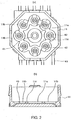
- Figs. 3 are views showing two sides of a component of a drive unit used in the multi-contact input device
- Figs. 4 are views showing three sides of another component of the drive unit used in the multi-contact input device
- Figs. 5 are views showing two sides of still another component of the drive unit used in the multi-contact input device
- Figs. 6 are view showing three sides of an operating member used in the multi-contact input device
- Fig. 7 is a vertical sectional view showing a pressing operation of the multi-contact input device
- Fig. 8 is a vertical sectional view showing an inclining operation of the multi-contact input device.
- a multi-contact input device comprises a case 10 housing various kinds of components, an annular drive unit 20 supported so that it can be inclined in the direction of entire circumference in the case 10, and a stick-shaped operating member 30 disposed substantially perpendicular to a base plane of the case to operate the drive unit 20.
- the case 10 consists of a box-shaped body 11 made of a resin and having a bottom plate portion or base, a lid 12 made of a resin to cover its upper opening, and a metal cover 13 mounted on the body 11 to cover the lid 12 to fix the lid 12 to the body 11.
- the body 11 made of the resin is almost an octagonal box in which its upper face is opened.
- a circular recessed part 11a is positioned in the center of an upper surface of a bottom plate and a plurality of circular recessed parts 11b (eight in this example) are provided so as to surround it.
- the plurality of recessed parts 11b is continued in the circumference direction and an annularly projected stop 11c is formed between those parts and the central recessed part 11a.
- a metal terminal 40 is insert-molded in the bottom plate of the body 11.
- a fixed contact 41 for a central switch is positioned in the center and a plurality of fixed contacts 42 (eight in this example) for peripheral switches is provided so as to surround this on a surface of the metal terminal 40.
- the fixed contact 41 for the central switch is positioned in the recessed part 11a and exposed to the surface side
- the plurality of fixed contacts 42 for the peripheral switches is positioned in the plurality of recessed parts 11b and exposed to the surface side.
- Reference numeral 43 designates a pulled-out lead of the metal terminal 40.
- a snap plate 51 which is a monostable movable diaphragm contact is provided over the fixed contact 41, and a plurality of snap plates 52 which are movable diaphragm contacts are provided over the plurality of fixed contacts 42.
- the snap plates 51 and 52 constitute the central switch and the peripheral switches in cooperation with the fixed contacts 41 and 42. That is, the snap plates 51 and 52 are housed in the corresponding recessed parts 11a and 11b, respectively and fixed in those recessed parts by a film applied from above to constitute the central switch and the peripheral switches.
- the lid 12 made of the resin is almost an octagonal plate corresponding to a planar configuration of the body 11 and has a circular opening 12a in its center to allow the operating member 30 to protrude through the case 10.
- a convex spherical press face 12b is provided on the peripheral surface of the opening 12a in order to support the drive unit 20 from above so that it can be freely inclined.
- the drive unit 20 will be described below.
- the metal plate cover 13 has almost an octagonal top plate corresponding to the planar configuration of the body 11.
- a circular opening 13a is provided in the center of the top plate to allow the operating member 30 to project through the case 10.
- the cover 13 also has a plurality of engagement parts projecting downward like tongues from the outer edge of the top plate. When each engagement part engages with a click-shaped projection formed on the outer periphery of a side wall of the body 11, the cover 13 is mounted on the body 11 and the lid 12 is fixed to the body 11.
- the drive unit 20 is housed in a cup-shaped retainer member 70 made of metal, in the case 10.
- the cup-shaped retainer member 70 comprises a cup-shaped main body 71 in which an upper surface is open with an annular supporting part 72 extending from an opening edge of the main body 71 toward the outer periphery like a flange.
- the main body 71 of the retainer member 70 has an almost elliptical opening 73 in the center in the bottom plate to project a part of the drive unit 20 downward as the operating part, and a plurality of openings 74 which surround it.
- the central opening 73 corresponds to the central switch and the peripheral openings 74 are provided to operate the plurality of peripheral switches.
- the supporting part 72 of the retainer member 70 is formed into almost an octagon corresponding to the planar configuration of the main body 11 so as to fit in it. Thus, the supporting part 72 is forced upward by a coil-shaped spring 60 housed in the main body 11 along its side wall and serving as a center return spring after inclination.
- the drive unit 20 is the annular member made of the resin which is housed in the main body 71 of the cup-shaped retainer member 70 and has a through-hole in the center.
- the drive unit 20 is forced upward by the above-described spring 60 together with the retainer member 70.
- a taper face 22, or flared through-hole, whose diameter gradually increases in an upward direction, is provided in an inner periphery of the dome part 21 in order to allow inclination of the operating member 30 relative to the drive unit 20 in a peripheral direction, in a manner which will be described below.
- a key top 23 which is an annular disk is provided at a lower part of the drive unit 20.
- the key top 23 is the annular disk having a diameter larger than that of the dome part 21, and a plurality of round rod-shaped operating parts 24 are projected from its outer periphery of a lower surface.
- the plurality of operating parts 24 project downward from the plurality of openings 74 provided in the main body 71 of the retainer member 70 in order to operate the plurality of peripheral switches.
- a plurality of arc-shaped recesses 25 (four in this example) is provided in the lower surface of the key top 23 so as to surround the through-hole in the center.
- a projection 29 for welding is provided so as to be positioned between adjacent recesses 25.
- the plurality of the arc-shaped recesses 25 is continued to the inner through-hole.
- a fixing board 26 shown in Fig. 5 is mounted on the center of the lower surface of the key top 23 by welding in order to cover the through-hole of the drive unit 20.
- the fixing board 26 also serves as a member for preventing the operating member 30 from a falling, and a circular through-hole 26a is provided in the center thereof in order to project a part of the operating member 30 downward.
- the fixing board 26 fits in the opening 73 provided in the center of the main body 71 of the retainer member 70 so that it cannot be rotated. Therefore, a plurality of semicircular projections 26b is provided on the outer periphery of the fixing board 26. In addition, a plurality of semicircular recesses 26c is provided in the outer periphery of the fixing board 26. The plurality of recesses 26c corresponds to the plurality of projections 29 provided on the lower surface of the key top 23, and the fixing board 26 is welded to the center of the lower surface of the key top 23 using these projections 29.
- the operating member 30 comprises a shaft-shaped operating member main body 31 and a push rod 32 incorporated in this.
- the operating member main body 31 is inserted from beneath to the through-hole provided in the center of the inner member 22 and its upper part penetrates the drive unit 20 and protrudes to an upper part of the case 10.
- An insertion hole 31a in which the push member 32 is slidably inserted is provided so as to be open downward in the center of the operating member main body 31.
- a plurality of locking parts 31b (four in this example) which extend to the outer periphery side is provided at an outer periphery of a lower end of the operating member main body 31.
- the locking parts 31b are arc-shaped stops which are inserted into the plurality of recesses 25 provided in the lower surface of the drive unit 20 and prevent the operating member main body 31 from coming out upward and stop rotation of the drive unit 20 in the axis direction.
- the push rod 32 comprises a large-diameter part 32a which is slidably inserted into the insertion hole 31a of the operating member main body 31, and a small-diameter operating part 32b protruding downward from the center of the lower surface of the large-diameter part 32a.
- the large-diameter part 32a is prevented from coming out by the above-described fixing board 26 and the small-diameter operating part 32b protrudes downward from the through-hole 26a of the fixing board 26 for operating the central switch.
- the push rod 32 is forced downward by the switch-protecting coil-shaped spring 33 which is inserted into the insertion hole 31a in a compressed state.
- the drive unit 20 housed in the case 10 is elastically retained in a neutral position by the spring 60 housed in the case 10 together with the drive unit 20. More specifically, as shown in Fig. 1, while the annular supporting part 72 of the retainer member 70 which houses the drive unit 20 is elastically pressed against the lid 12 of the case 10 by the spring 60, the drive unit 20 is elastically held in the neutral position.
- the operating member 30 which penetrates the drive unit 20 is also elastically held in the vertical neutral position. That is, the spring 60 is a center return spring which elastically holds the operating member 30 in the neutral position and automatically brings it to the neutral position.
- the plurality of operating parts 24 provided on the lower surface of the key top 23 of the drive unit 20 is separated from the snap plates 52 of the plurality of corresponding peripheral switches.
- the main body 31 of the operating member 30 is forced upward by the spring 33.
- the push rod 32 forced downward is spaced from the snap plate 51 of the corresponding central switch or, if it is not spaced therefrom, it abuts on the snap plate 51 slightly.
- the elastic force of the spring 33 incorporated in the operating member 30 is stronger than that of the spring 60 forcing the drive unit 20. That is, when the operating member 30 is pressed downward from the neutral state shown in Fig. 1, although the spring 60 shrinks and moves the drive unit 20 downward, the spring 33 in the operating member 30 does not shrink. In addition, when the operating member 30 is inclined from the neutral position to the periphery, the spring 60 is deformed according to the operation and inclines the drive unit 20 but the spring 33 in the operating member 30 does not shrink. As a result, the operating member 30 holds the neutral position, that is, the vertical state with respect to the drive unit 20.
- the plurality of operating parts 24 provided on the lower surface of the drive unit 20 is spaced from the snap plates 52 of the corresponding plurality of peripheral switches.
- the fixing board 26 welded to the drive unit 20 is spaced from the annular stop 11c provided on the upper surface of the bottom plate of the body 11.
- the peripheral switch is switched from the off state to the on state, so that the inclined direction of the operating member 30 can be detected.
- the inclination of the operating member 30 at this time becomes the over stroke and a sense of operation is further improved. Since the spring 33 for protecting the central switch is used in this inclination, a spring for the over stroke in the inclined direction is not needed.
- the force applied to the peripheral switch does not exceed the force of the spring 33. Therefore, the peripheral switch can be effectively prevented from being damaged.
- Fig. 9 is a vertical sectional view showing a multi-contact input device according to another embodiment of the present invention.
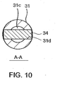
- Fig. 10 is a view taken in the direction of arrows A-A of Fig. 9.
- Figs. 11 are vertical sectional views showing an operating member which is a main part of the multi-contact input device in the order of assembly, and
- Figs. 12(a) and (b) are vertical sectional views showing an operation of the multi-contact input device.
- the multi-contact input device according to this embodiment is largely different from the above-described multi-contact input device shown in Figs. 1 to 8 in the structures of the operating member 30, the drive unit 20 and its retainer member 70. First, the operating member 30 will be described in detail.
- the insertion hole 31a which is opened downward is provided in the main body 31 of the operating member 30 and, after the spring 33 and the push rod 32 are inserted into this from beneath, the insertion hole 31a is sealed by the bottom plate 26 mounted on the lower surface of the drive unit 20.
- the bottom plate 26 of the drive unit 20 also serves as the stop which holds the operating member 30 inside the drive unit 20 and holds the push rod 32 in the operating member main body 31.
- a housing hole 31c penetrating the center part of the operating member main body 31 in the axis direction is provided.
- a diameter at a lower end is decreased in order to prevent the push rod 32 from falling down and an entire surface is opened upward in order to introduce the push rod 32 and the spring 33.
- a plug body 34 which penetrates the operating member main body 31 at right angles is used.
- an insertion hole 31d having a square section is provided in the operating member main body 31 so that the section intersects with the housing hole 31c having a circular section at right angles.
- the push rod 32 and the spring 33 are inserted to the housing hole 31c of the operating member main body 31 from above and the plug body 34 is inserted to the insertion hole 31d from the side of the operating member main body 31 in a state in which the spring 33 is compressed in the inserting direction (downward), so that the push rod 32 and the spring 33 are enclosed in the operating member main body 31.
- the insertion hole 31d is provided so as to be positioned on the compressed spring 33.
- the push rod 32 and the spring 33 are enclosed in the main body 31 of the operating member 30 and the push rod 32 is forced downward.
- the plug body 34 is pressed upward in the insertion hole 31d, the plug body 34 is prevented from coming out.
- a recess 34a in which an upper part of the spring 33 fits is provided on a lower surface of the plug body 34.
- the drive unit 20 made of a resin is integrated with the main body 31 of the operating member 30 formed of the resin also.
- a disk-shaped key top 23 is provided at a lower part of the drive unit 20 and a plurality of convex operating parts 24 corresponding to a plurality of peripheral switches are provided in an outer periphery of its lower surface.
- a metal retainer member 70 which retains the drive unit 20 is formed into an inversed cap which fits the drive unit 20 from above, and a spring 60 which elastically holds the drive unit 20 in a neutral position is housed between a flange-shaped supporting part 72 of the cup-shaped retainer member 70 and a cover 13 which is a top plate of a case 10, in a compressed state to force the retainer member 70 downward.
- the drive unit 20 and the operating member 30 in the retainer member 70 are forced downward by the spring 60 together with the retainer member 70 and elastically held in the neutral position.
- the force of the spring 33 in the operating member 30 is stronger than restoring force of the snap plate 51 in the central switch. Therefore, when the operating member 30 is pressed downward by a force stronger than the restoring force of the snap plate 51 in the central switch, the central switch is operated.
- the central switch is prevented from being damaged in the case of dropping, for example like the case of the above-described multi-contact input device shown in Figs. 1 to 8.
- the peripheral switch can be operated.
- the drive unit 20 is inclined to the periphery centering around the bottom surface of the push rod 32 first, and the peripheral switch positioned in the operated direction is pressed and operated by the operating part 24 of the drive unit 20.
- the drive unit 20 is inclined in the retainer member 70 and the retainer member 70 is also inclined.
- Fig. 13 is a vertical sectional view showing a multi-contact input device according to still another embodiment of the present invention.
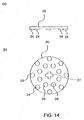
- Figs. 14(a) and (b) are views showing two sides of a drive unit used in the above multi-contact input device.
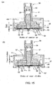
- Figs. 15(a) and (b) are vertical sectional views showing an operation of that multi-contact input device, and
- Figs. 16(a) and (b) are vertical sectional views showing another operation of that multi-contact input device.
- the multi-contact input device is different from the above-described multi-contact input device shown in Figs. 9 to 12 in the structure of the drive unit 20.
- the drive unit 20 comprises a convex dome part 21 at an upper part and the annular disk-shaped key top 23 continued from the upper part at a lower part, which are integrated with the main body 31 of the operating member 30.
- the drive unit 20 is an annular disk corresponding to the above-described key top 23 and bonded to a projection end which protrudes from a push rod 32 of an operating member 30, more specifically from an operating member main body 31 of the push rod 32 by welding.
- a dome part corresponding to a dome part 21 of the drive unit 20 is integrated with the main body 31 of the operating member 30 as a retaining part 37 which fits in a retainer member 70.
- a plurality of round rod-shaped projections 38 is provided on a lower surface of the retaining part 37 as stops for the pressing operation.
- the disk-shaped drive unit 20 arranged on the lower side of the retaining part 37 is bonded to a projection end of the push rod 32 of the operating member 30 so as to be slightly spaced from the upper retaining part 37.
- a first through-hole 27 to which a tip end of the push rod 32 is inserted is provided in the center and a plurality of second through-holes 28 in which the round rod-shaped projections 38 provided on the lower surface of the retaining part 37 are inserted are provided so as to surround the first through-hole 27 of the drive unit 20.
- a plurality of convex operating parts 24 corresponding to a plurality of peripheral switches is provided on the outer periphery of the lower surface of the drive unit 20 so as to be spaced at the same intervals in the peripheral direction.
- the tip end of the push rod 32 and the first through-hole 27 into which it is inserted are formed into a cross shape to position the drive unit 20 in the circumferential direction.
- a body 11 made of a resin which constitutes a case 10 has an annular convex stop 11c on an upper surface of the bottom plate so as to correspond to the plurality of projections 38. Its other features are essentially the same as those of the multi-contact input device shown in Figs. 9 to 12.
- the operating member 30 in the retainer member 70 is forced downward together with the retainer member 70 by a spring 60 and it is elastically retained in a neutral position.
- the push rod 32 in the operating member 30 is forced downward together with the drive unit 20 by a spring 33 and is slightly in contact with the snap plate 51 of the central switch. This force is stronger than restoring force of the snap plate 51 of the central switch. Therefore, when the operating member 30 is pressed downward by a force stronger than the restoring force of the snap plate 51, the central switch is operated by the tip end of the push rod 32 as shown in Fig. 15(a).
- a gap is provided between an annular stop 11c provided in the body 11 of the case 10 and the plurality of projections 38 provided on a lower surface of the operating member 30.
- the force of the spring 33 in the operating member 30 is set such that it is stronger than the restoring force of the central switch, and plastic deformation (damage) of the snap plate 51 does not occur. Therefore, when the operating member 30 is further pressed downward, as shown in Fig. 15 (b), the main body 31 of the operating member 30 is pressed downward until the plurality of projections 38 come into contact with the stop 11c, but the push rod 32 is retracted into the operating member main body 31.
- the outer force applied to the central switch is the force of the spring 33 at most. Therefore, like the case of the above-described multi-contact input device, the central switch is prevented from being damaged if the operating member 30 receives excessive outer force in the axis direction. In addition, the over stroke in the pressing direction can be ensured.
- the peripheral switch can be operated.
- the drive unit 20 mounted on the push rod 32 is inclined to the periphery, centering around the bottom surface of the push rod 32, and the peripheral switch positioned in the inclined direction is pressed by the operating part 24.
- the retainer member 70 is also inclined at the same time.
- the operating member 30 is inclined using the operating part 24 as a supporting point
- the retainer member 70 is inclined using a part which is in contact with the bottom plate of the body 11 as a supporting point.
- an over stroke is provided by the above operation.
- reaction force from the peripheral switch is transferred to the push rod 32 of the operating member 30 through the drive unit 20 and the push rod 32 retracts into the operating member main body 31 against the force of the spring 33, so that the drive unit 20 is relatively moved in a retracting direction.
- the over stroke is increased in the inclining direction by the relative movement of the push rod 32 and a sense of operation can be improved.
- the central switch and peripheral switch can be prevented from being damaged while the large over stroke is provided like the multi-contact input device according to the other embodiments.
- a plurality of projections can be provided in the vicinity of the center of a fixed contact 42 of the peripheral switch, and a plurality of projections can be provided in the vicinity of a top of the snap plate 51 of the central switch.
- the plurality of projections can be provided in the vicinity of the top of the snap plate 52 of the peripheral switch and the plurality of projections can be provided in the vicinity of the center of the fixed contact 41 of the central switch.
Landscapes
- Physics & Mathematics (AREA)
- General Physics & Mathematics (AREA)
- Engineering & Computer Science (AREA)
- Automation & Control Theory (AREA)
- Switches With Compound Operations (AREA)
Applications Claiming Priority (2)
| Application Number | Priority Date | Filing Date | Title |
|---|---|---|---|
| JP2004232795 | 2004-08-09 | ||
| JP2005137871A JP4418399B2 (ja) | 2004-08-09 | 2005-05-10 | 多接点入力装置 |
Publications (3)
| Publication Number | Publication Date |
|---|---|
| EP1626424A2 true EP1626424A2 (de) | 2006-02-15 |
| EP1626424A3 EP1626424A3 (de) | 2006-09-06 |
| EP1626424B1 EP1626424B1 (de) | 2014-10-15 |
Family
ID=35149554
Family Applications (1)
| Application Number | Title | Priority Date | Filing Date |
|---|---|---|---|
| EP05254938.3A Ceased EP1626424B1 (de) | 2004-08-09 | 2005-08-08 | Eingabevorrichtung mit mehreren Kontakten |
Country Status (4)
| Country | Link |
|---|---|
| US (1) | US7176392B2 (de) |
| EP (1) | EP1626424B1 (de) |
| JP (1) | JP4418399B2 (de) |
| CN (1) | CN1734693B (de) |
Cited By (2)
| Publication number | Priority date | Publication date | Assignee | Title |
|---|---|---|---|---|
| EP3629353A1 (de) * | 2018-09-25 | 2020-04-01 | Hosiden Corporation | Multidirektionale eingabevorrichtung |
| EP3745437A1 (de) * | 2019-05-29 | 2020-12-02 | Defond Electech Co., Ltd | Bâton de contrôle |
Families Citing this family (14)
| Publication number | Priority date | Publication date | Assignee | Title |
|---|---|---|---|---|
| US7333092B2 (en) | 2002-02-25 | 2008-02-19 | Apple Computer, Inc. | Touch pad for handheld device |
| EP1533825A1 (de) * | 2003-11-21 | 2005-05-25 | Bang & Olufsen A/S | Auswahlvorrichtung mit Mehrfachschalter |
| US8022935B2 (en) | 2006-07-06 | 2011-09-20 | Apple Inc. | Capacitance sensing electrode with integrated I/O mechanism |
| US8274479B2 (en) * | 2006-10-11 | 2012-09-25 | Apple Inc. | Gimballed scroll wheel |
| DE102007013678A1 (de) * | 2007-03-22 | 2008-09-25 | Preh Gmbh | Bedienelement für ein Kraftfahrzeug |
| JP4551915B2 (ja) | 2007-07-03 | 2010-09-29 | ホシデン株式会社 | 複合操作型入力装置 |
| CN101576770B (zh) * | 2008-05-07 | 2011-09-21 | 联想(北京)有限公司 | 多触点交互系统及方法 |
| JP5360509B2 (ja) * | 2011-03-24 | 2013-12-04 | 株式会社デンソー | 操作入力装置 |
| KR101386070B1 (ko) | 2013-03-13 | 2014-04-16 | 리모트솔루션주식회사 | 다접점을 갖춘 슬라이딩 스위치 |
| CN204792582U (zh) * | 2015-07-27 | 2015-11-18 | 东莞市凯华电子有限公司 | 新型游戏摇杆开关 |
| CN108183047B (zh) * | 2018-01-10 | 2019-05-17 | 东方电气集团东方汽轮机有限公司 | 一种多通道机械式加速度开关 |
| CN111199845B (zh) * | 2020-02-11 | 2020-09-25 | 永康串行电子有限公司 | 一种多触点的电开关 |
| CN111668056B (zh) * | 2020-06-29 | 2025-04-25 | 深圳市致尚科技股份有限公司 | 多方向输入装置、手柄及游戏机 |
| JP7217311B2 (ja) * | 2021-05-19 | 2023-02-02 | ヤマハ発動機株式会社 | ハンドルスイッチおよび鞍乗型車両 |
Citations (2)
| Publication number | Priority date | Publication date | Assignee | Title |
|---|---|---|---|---|
| DE4443726A1 (de) | 1993-12-08 | 1995-06-14 | Alps Electric Co Ltd | Mehrrichtungs-Eingabeschalter |
| JPH07307124A (ja) | 1994-05-11 | 1995-11-21 | Matsushita Electric Ind Co Ltd | スイッチ |
Family Cites Families (20)
| Publication number | Priority date | Publication date | Assignee | Title |
|---|---|---|---|---|
| US4156802A (en) * | 1977-06-10 | 1979-05-29 | Telaris Telecommunications, Inc. | Electrical switch assembly |
| US4315113A (en) * | 1980-01-18 | 1982-02-09 | Harman International Industries, Inc. | Actuator switch for remote control rearview mirrors |
| US4280027A (en) * | 1980-05-27 | 1981-07-21 | The Singer Company | Switch blade mechanism and multi-arrangement |
| JPH01302621A (ja) | 1988-05-30 | 1989-12-06 | Hitachi Ltd | キートップアレイ |
| US5231386A (en) | 1990-07-24 | 1993-07-27 | Home Row, Inc. | Keyswitch-integrated pointing assembly |
| US5691517A (en) * | 1993-11-19 | 1997-11-25 | Sumitomo Wiring Systems, Ltd. | Multidirectional lever switch device |
| JP3221254B2 (ja) | 1994-10-14 | 2001-10-22 | 松下電器産業株式会社 | 多方向操作スイッチ |
| GB2341664B (en) * | 1996-05-18 | 2000-10-11 | Penny & Giles Controls Ltd | Electrical joystick controller |
| JPH10154445A (ja) | 1996-09-29 | 1998-06-09 | Hosiden Corp | コントロールスイッチ |
| JP3410007B2 (ja) | 1997-11-26 | 2003-05-26 | ホシデン株式会社 | 多方向キースイッチ |
| JP3875438B2 (ja) * | 1999-12-16 | 2007-01-31 | アルプス電気株式会社 | 多方向操作スイッチ |
| JP4414037B2 (ja) * | 1999-12-28 | 2010-02-10 | 株式会社日立国際電気 | スイッチ装置 |
| JP3710668B2 (ja) | 2000-02-14 | 2005-10-26 | ホシデン株式会社 | 多接点入力装置 |
| JP2001283690A (ja) * | 2000-03-29 | 2001-10-12 | Hosiden Corp | 多接点入力装置 |
| JP3819676B2 (ja) * | 2000-06-02 | 2006-09-13 | アルプス電気株式会社 | 多方向スイッチ |
| US6593909B1 (en) * | 2000-06-29 | 2003-07-15 | Shin Jiuh Corp. | Direction-control switch module for controlling a screen cursor |
| JP2003217397A (ja) * | 2002-01-25 | 2003-07-31 | Matsushita Electric Ind Co Ltd | 回転操作型電子部品 |
| JP3864812B2 (ja) * | 2002-03-07 | 2007-01-10 | 松下電器産業株式会社 | 複合操作型電子部品 |
| TW570281U (en) * | 2002-08-06 | 2004-01-01 | Excel Cell Elect Co Ltd | Multi-directional trigger switch |
| KR20040043896A (ko) | 2002-11-20 | 2004-05-27 | 삼성전자주식회사 | 푸시버튼 |
-
2005
- 2005-05-10 JP JP2005137871A patent/JP4418399B2/ja not_active Expired - Fee Related
- 2005-08-08 EP EP05254938.3A patent/EP1626424B1/de not_active Ceased
- 2005-08-08 US US11/198,907 patent/US7176392B2/en not_active Expired - Fee Related
- 2005-08-09 CN CN200510090018.6A patent/CN1734693B/zh not_active Expired - Fee Related
Patent Citations (2)
| Publication number | Priority date | Publication date | Assignee | Title |
|---|---|---|---|---|
| DE4443726A1 (de) | 1993-12-08 | 1995-06-14 | Alps Electric Co Ltd | Mehrrichtungs-Eingabeschalter |
| JPH07307124A (ja) | 1994-05-11 | 1995-11-21 | Matsushita Electric Ind Co Ltd | スイッチ |
Non-Patent Citations (1)
| Title |
|---|
| PATENT ABSTRACTS OF JAPAN, vol. 1996, no. 03, 29 March 1996 (1996-03-29) |
Cited By (5)
| Publication number | Priority date | Publication date | Assignee | Title |
|---|---|---|---|---|
| EP3629353A1 (de) * | 2018-09-25 | 2020-04-01 | Hosiden Corporation | Multidirektionale eingabevorrichtung |
| US10768658B2 (en) | 2018-09-25 | 2020-09-08 | Hosiden Corporation | Multi-directional input device |
| EP4084036A3 (de) * | 2018-09-25 | 2023-01-25 | Hosiden Corporation | Multidirektionale eingabevorrichtung |
| EP4220678A1 (de) * | 2018-09-25 | 2023-08-02 | Hosiden Corporation | Multidirektionale eingabevorrichtung |
| EP3745437A1 (de) * | 2019-05-29 | 2020-12-02 | Defond Electech Co., Ltd | Bâton de contrôle |
Also Published As
| Publication number | Publication date |
|---|---|
| CN1734693B (zh) | 2010-05-05 |
| JP2006080053A (ja) | 2006-03-23 |
| US7176392B2 (en) | 2007-02-13 |
| JP4418399B2 (ja) | 2010-02-17 |
| CN1734693A (zh) | 2006-02-15 |
| US20060060455A1 (en) | 2006-03-23 |
| EP1626424B1 (de) | 2014-10-15 |
| EP1626424A3 (de) | 2006-09-06 |
Similar Documents
| Publication | Publication Date | Title |
|---|---|---|
| EP1626424A2 (de) | Eingabevorrichtung mit mehreren Kontakten | |
| US6979785B2 (en) | Multidirectional operation switch | |
| JP4353964B2 (ja) | 複合操作型入力装置 | |
| JP3179036U (ja) | プッシュスイッチ | |
| US6423911B2 (en) | Multi-directional operating switch capable of being operated in both depressing direction and tilting direction | |
| KR100325595B1 (ko) | 다방향 입력장치 | |
| US7534972B2 (en) | Electrical switch | |
| JP4674167B2 (ja) | スライド操作式スイッチ | |
| JP3816664B2 (ja) | 多方向スイッチおよびこの多方向スイッチを用いた電子機器 | |
| JP4241798B2 (ja) | 回転形パルススイッチ | |
| JPH07245042A (ja) | 多方向入力スイッチ | |
| JP2006324083A (ja) | 多方向入力装置 | |
| JP2913277B2 (ja) | 多方向入力スイッチ | |
| JP3883390B2 (ja) | 多方向入力装置 | |
| KR0140661B1 (ko) | 푸시버튼 스위치 | |
| JP3183866B2 (ja) | 多方向入力スイッチ | |
| EP4636800A1 (de) | Doppelpolschalter | |
| JP2020155317A (ja) | 押釦スイッチ | |
| JP3682062B1 (ja) | 多方向スイッチ | |
| JP4522376B2 (ja) | 多方向入力装置 | |
| JP3862481B2 (ja) | 多方向入力装置 | |
| JP2003123594A (ja) | 多方向スイッチ | |
| JP7055371B2 (ja) | 多方向押圧型スイッチ | |
| JPH0850834A (ja) | 押し釦スイッチ付きロータリースイッチ | |
| WO2023248701A1 (ja) | プッシュスイッチ |
Legal Events
| Date | Code | Title | Description |
|---|---|---|---|
| PUAI | Public reference made under article 153(3) epc to a published international application that has entered the european phase |
Free format text: ORIGINAL CODE: 0009012 |
|
| AK | Designated contracting states |
Kind code of ref document: A2 Designated state(s): AT BE BG CH CY CZ DE DK EE ES FI FR GB GR HU IE IS IT LI LT LU LV MC NL PL PT RO SE SI SK TR |
|
| AX | Request for extension of the european patent |
Extension state: AL BA HR MK YU |
|
| PUAL | Search report despatched |
Free format text: ORIGINAL CODE: 0009013 |
|
| AK | Designated contracting states |
Kind code of ref document: A3 Designated state(s): AT BE BG CH CY CZ DE DK EE ES FI FR GB GR HU IE IS IT LI LT LU LV MC NL PL PT RO SE SI SK TR |
|
| AX | Request for extension of the european patent |
Extension state: AL BA HR MK YU |
|
| RIC1 | Information provided on ipc code assigned before grant |
Ipc: G05G 9/047 20060101ALI20060728BHEP Ipc: H01H 25/04 20060101AFI20051104BHEP |
|
| 17P | Request for examination filed |
Effective date: 20070302 |
|
| 17Q | First examination report despatched |
Effective date: 20070330 |
|
| AKX | Designation fees paid |
Designated state(s): DE FR GB IT |
|
| GRAP | Despatch of communication of intention to grant a patent |
Free format text: ORIGINAL CODE: EPIDOSNIGR1 |
|
| INTG | Intention to grant announced |
Effective date: 20140226 |
|
| GRAS | Grant fee paid |
Free format text: ORIGINAL CODE: EPIDOSNIGR3 |
|
| GRAA | (expected) grant |
Free format text: ORIGINAL CODE: 0009210 |
|
| AK | Designated contracting states |
Kind code of ref document: B1 Designated state(s): DE FR GB IT |
|
| REG | Reference to a national code |
Ref country code: GB Ref legal event code: FG4D |
|
| REG | Reference to a national code |
Ref country code: DE Ref legal event code: R096 Ref document number: 602005044924 Country of ref document: DE Effective date: 20141127 |
|
| REG | Reference to a national code |
Ref country code: DE Ref legal event code: R097 Ref document number: 602005044924 Country of ref document: DE |
|
| PLBE | No opposition filed within time limit |
Free format text: ORIGINAL CODE: 0009261 |
|
| STAA | Information on the status of an ep patent application or granted ep patent |
Free format text: STATUS: NO OPPOSITION FILED WITHIN TIME LIMIT |
|
| 26N | No opposition filed |
Effective date: 20150716 |
|
| REG | Reference to a national code |
Ref country code: FR Ref legal event code: PLFP Year of fee payment: 12 |
|
| REG | Reference to a national code |
Ref country code: FR Ref legal event code: PLFP Year of fee payment: 13 |
|
| PGFP | Annual fee paid to national office [announced via postgrant information from national office to epo] |
Ref country code: DE Payment date: 20170801 Year of fee payment: 13 Ref country code: IT Payment date: 20170824 Year of fee payment: 13 Ref country code: GB Payment date: 20170802 Year of fee payment: 13 Ref country code: FR Payment date: 20170714 Year of fee payment: 13 |
|
| REG | Reference to a national code |
Ref country code: DE Ref legal event code: R119 Ref document number: 602005044924 Country of ref document: DE |
|
| GBPC | Gb: european patent ceased through non-payment of renewal fee |
Effective date: 20180808 |
|
| PG25 | Lapsed in a contracting state [announced via postgrant information from national office to epo] |
Ref country code: DE Free format text: LAPSE BECAUSE OF NON-PAYMENT OF DUE FEES Effective date: 20190301 Ref country code: IT Free format text: LAPSE BECAUSE OF NON-PAYMENT OF DUE FEES Effective date: 20180808 |
|
| PG25 | Lapsed in a contracting state [announced via postgrant information from national office to epo] |
Ref country code: FR Free format text: LAPSE BECAUSE OF NON-PAYMENT OF DUE FEES Effective date: 20180831 |
|
| PG25 | Lapsed in a contracting state [announced via postgrant information from national office to epo] |
Ref country code: GB Free format text: LAPSE BECAUSE OF NON-PAYMENT OF DUE FEES Effective date: 20180808 |