EP1625309B1 - Blindniete und einsatz verfahren derselben - Google Patents
Blindniete und einsatz verfahren derselben Download PDFInfo
- Publication number
- EP1625309B1 EP1625309B1 EP04729672A EP04729672A EP1625309B1 EP 1625309 B1 EP1625309 B1 EP 1625309B1 EP 04729672 A EP04729672 A EP 04729672A EP 04729672 A EP04729672 A EP 04729672A EP 1625309 B1 EP1625309 B1 EP 1625309B1
- Authority
- EP
- European Patent Office
- Prior art keywords
- fastener
- workpiece
- face
- hole
- leading end
- Prior art date
- Legal status (The legal status is an assumption and is not a legal conclusion. Google has not performed a legal analysis and makes no representation as to the accuracy of the status listed.)
- Expired - Lifetime
Links
- 238000009434 installation Methods 0.000 title claims abstract description 12
- 238000000034 method Methods 0.000 title claims description 22
- 229920001169 thermoplastic Polymers 0.000 claims abstract description 20
- 239000004416 thermosoftening plastic Substances 0.000 claims abstract description 20
- 238000005553 drilling Methods 0.000 claims abstract description 6
- 238000010438 heat treatment Methods 0.000 claims description 3
- 230000006698 induction Effects 0.000 claims description 2
- 239000000463 material Substances 0.000 claims description 2
- 230000010355 oscillation Effects 0.000 claims description 2
- 238000004519 manufacturing process Methods 0.000 description 3
- 230000000717 retained effect Effects 0.000 description 3
- 230000015572 biosynthetic process Effects 0.000 description 2
- 229910001209 Low-carbon steel Inorganic materials 0.000 description 1
- 230000004323 axial length Effects 0.000 description 1
- 230000004888 barrier function Effects 0.000 description 1
- 230000005540 biological transmission Effects 0.000 description 1
- 239000012530 fluid Substances 0.000 description 1
- 238000007689 inspection Methods 0.000 description 1
Images


Classifications
-
- F—MECHANICAL ENGINEERING; LIGHTING; HEATING; WEAPONS; BLASTING
- F16—ENGINEERING ELEMENTS AND UNITS; GENERAL MEASURES FOR PRODUCING AND MAINTAINING EFFECTIVE FUNCTIONING OF MACHINES OR INSTALLATIONS; THERMAL INSULATION IN GENERAL
- F16B—DEVICES FOR FASTENING OR SECURING CONSTRUCTIONAL ELEMENTS OR MACHINE PARTS TOGETHER, e.g. NAILS, BOLTS, CIRCLIPS, CLAMPS, CLIPS OR WEDGES; JOINTS OR JOINTING
- F16B37/00—Nuts or like thread-engaging members
- F16B37/04—Devices for fastening nuts to surfaces, e.g. sheets, plates
- F16B37/06—Devices for fastening nuts to surfaces, e.g. sheets, plates by means of welding or riveting
- F16B37/062—Devices for fastening nuts to surfaces, e.g. sheets, plates by means of welding or riveting by means of riveting
- F16B37/065—Devices for fastening nuts to surfaces, e.g. sheets, plates by means of welding or riveting by means of riveting by deforming the material of the nut
- F16B37/067—Devices for fastening nuts to surfaces, e.g. sheets, plates by means of welding or riveting by means of riveting by deforming the material of the nut the material of the nut being deformed by a threaded member generating axial movement of the threaded part of the nut, e.g. blind rivet type
-
- F—MECHANICAL ENGINEERING; LIGHTING; HEATING; WEAPONS; BLASTING
- F16—ENGINEERING ELEMENTS AND UNITS; GENERAL MEASURES FOR PRODUCING AND MAINTAINING EFFECTIVE FUNCTIONING OF MACHINES OR INSTALLATIONS; THERMAL INSULATION IN GENERAL
- F16B—DEVICES FOR FASTENING OR SECURING CONSTRUCTIONAL ELEMENTS OR MACHINE PARTS TOGETHER, e.g. NAILS, BOLTS, CIRCLIPS, CLAMPS, CLIPS OR WEDGES; JOINTS OR JOINTING
- F16B19/00—Bolts without screw-thread; Pins, including deformable elements; Rivets
- F16B19/04—Rivets; Spigots or the like fastened by riveting
- F16B19/08—Hollow rivets; Multi-part rivets
- F16B19/10—Hollow rivets; Multi-part rivets fastened by expanding mechanically
- F16B19/1027—Multi-part rivets
- F16B19/1036—Blind rivets
-
- F—MECHANICAL ENGINEERING; LIGHTING; HEATING; WEAPONS; BLASTING
- F16—ENGINEERING ELEMENTS AND UNITS; GENERAL MEASURES FOR PRODUCING AND MAINTAINING EFFECTIVE FUNCTIONING OF MACHINES OR INSTALLATIONS; THERMAL INSULATION IN GENERAL
- F16B—DEVICES FOR FASTENING OR SECURING CONSTRUCTIONAL ELEMENTS OR MACHINE PARTS TOGETHER, e.g. NAILS, BOLTS, CIRCLIPS, CLAMPS, CLIPS OR WEDGES; JOINTS OR JOINTING
- F16B29/00—Screwed connection with deformation of nut or auxiliary member while fastening
-
- F—MECHANICAL ENGINEERING; LIGHTING; HEATING; WEAPONS; BLASTING
- F16—ENGINEERING ELEMENTS AND UNITS; GENERAL MEASURES FOR PRODUCING AND MAINTAINING EFFECTIVE FUNCTIONING OF MACHINES OR INSTALLATIONS; THERMAL INSULATION IN GENERAL
- F16B—DEVICES FOR FASTENING OR SECURING CONSTRUCTIONAL ELEMENTS OR MACHINE PARTS TOGETHER, e.g. NAILS, BOLTS, CIRCLIPS, CLAMPS, CLIPS OR WEDGES; JOINTS OR JOINTING
- F16B37/00—Nuts or like thread-engaging members
- F16B37/04—Devices for fastening nuts to surfaces, e.g. sheets, plates
- F16B37/06—Devices for fastening nuts to surfaces, e.g. sheets, plates by means of welding or riveting
- F16B37/062—Devices for fastening nuts to surfaces, e.g. sheets, plates by means of welding or riveting by means of riveting
- F16B37/068—Devices for fastening nuts to surfaces, e.g. sheets, plates by means of welding or riveting by means of riveting by deforming the material of the support, e.g. the sheet or plate
-
- F—MECHANICAL ENGINEERING; LIGHTING; HEATING; WEAPONS; BLASTING
- F16—ENGINEERING ELEMENTS AND UNITS; GENERAL MEASURES FOR PRODUCING AND MAINTAINING EFFECTIVE FUNCTIONING OF MACHINES OR INSTALLATIONS; THERMAL INSULATION IN GENERAL
- F16B—DEVICES FOR FASTENING OR SECURING CONSTRUCTIONAL ELEMENTS OR MACHINE PARTS TOGETHER, e.g. NAILS, BOLTS, CIRCLIPS, CLAMPS, CLIPS OR WEDGES; JOINTS OR JOINTING
- F16B19/00—Bolts without screw-thread; Pins, including deformable elements; Rivets
- F16B19/04—Rivets; Spigots or the like fastened by riveting
- F16B19/08—Hollow rivets; Multi-part rivets
- F16B19/086—Self-piercing rivets
-
- Y—GENERAL TAGGING OF NEW TECHNOLOGICAL DEVELOPMENTS; GENERAL TAGGING OF CROSS-SECTIONAL TECHNOLOGIES SPANNING OVER SEVERAL SECTIONS OF THE IPC; TECHNICAL SUBJECTS COVERED BY FORMER USPC CROSS-REFERENCE ART COLLECTIONS [XRACs] AND DIGESTS
- Y10—TECHNICAL SUBJECTS COVERED BY FORMER USPC
- Y10T—TECHNICAL SUBJECTS COVERED BY FORMER US CLASSIFICATION
- Y10T29/00—Metal working
- Y10T29/49—Method of mechanical manufacture
- Y10T29/49826—Assembling or joining
- Y10T29/49945—Assembling or joining by driven force fit
Definitions
- the present invention relates in one of its aspects to a blind fastener, and in another of its aspects to a method of installation of such a blind fastener into a suitable workpiece, see US-A-4 499 647 according to the preamble of the independent product claim 1, and independent method claim 9.
- fastener is used to include, for example, a rivet which secures together two or more members forming a workpiece, and also, for example, a threaded insert which, when installed in a workpiece, allows a screw to be engaged therewith to secure another member to the workpiece.
- a threaded insert may be such that it will also secure together two or more members forming a workpiece.
- blind is meant a fastener which can be installed in the workpiece by access to only the front or near side of the workpiece.
- the present invention aims to provide a fastener, and a method of installation of such a fastener, which overcomes these disadvantages.
- the present invention provides, in one of its aspects, a blind fastener as set out in appended claim 1.
- the present invention also provides a method of forming a hole in a thermoplastic workpiece as set out in appended claim 10.
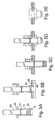
- Figure 1A is a longitudinal axial section through a threaded insert 11.
- Figure 1B is a cross-section on the line 1B-1B
- Figure 1C is a section on the line 1C-1C.
- the insert is made of low-carbon steel, and this example is 21.5mm in overall length, has a hexagonal body with an across-flats dimension of 9mm and has an M6 internal thread 12. At one end the insert has a radially enlarged head 13 with lugs 14 projecting from its underside.
- the body comprises a relatively thin-walled collapsible portion 15 adjacent the head, followed by an internally threaded portion 16 containing the M6 thread 12. Projecting beyond the remote end of the threaded portion 16 is a rim 17, comprising first a parallel part 18 and then an inwardly tapered part 19, bearing a flat end face 21.
- the wall thickness of the rim is as small as practicable, having regard to the needs of manufacturing and handling of the inserts.
- the tapering part 19 of the rim is at an angle of 30° to the insert axis, which has been found to be the optimum angle for this example insert.
- the total axial length of the rim 17 should be approximately equal to, or greater than, the thickness of the thermoplastic workpiece in which it is to be used.
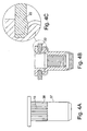
- FIG. 1D A possible alternative cross-sectional shape for the rim 17 is shown in Figure 1D .
- the insert 11 is mounted on a tool 23 comprising an elongated mandrel 24 with an end portion 25 which is externally threaded and engages the thread 12 of the internally threaded portion 16 of the insert.
- the tool also comprises a cylindrical body 26, through which the mandrel 24 extends and projects, having a flat end face 27 providing an anvil which engages the end face of the insert head 13.
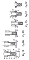
- the fastener is offered up to the workpiece 22 in the appropriate place so that the end face 21 of the rim contacts the near face (the upper face as shown in Figures 2A-2F ). Heat is applied to the contacted area of the workpiece by means of the rim face 21 (by means which will be described later). Pressure is also applied to the contacted area, by pushing the tool 23 towards the workpiece.
- the consequent local softening of the workpiece 22 allows the front part 19 of the rim to enter the workpiece.
- the rim progressively penetrates the workpiece thickness
- Figure 2C shows the rim having broken through the lower surface of the workpiece.
- the rim 17 has cut out a slug 28 of the workpiece material, which slug is retained in the rim by virtue of the slug flowing and then solidifying to fill the larger diameter part of the aperture within the rim provided by its increasing internal diameter further away from the end face 21.
- Figure 2D shows the insert fully pushed into hole 29 which has been formed by the insert.
- the lugs 14 under the insert body head 13 have locally softened and entered into the upper face of the workpiece 22, so as to provide additional resistance to the insert body rotating with respect to the workpiece.
- the tool is then operated to axially withdraw the mandrel 24, whilst supporting the head 13 against the end anvil face 27 of the tool body 26.
- This causes the collapsible portion 15 of the insert body to fold outwardly to form a flange 31, as shown in Figure 2E , which clamps the insert to the workpiece by reaction against the insert head 13.
- the tool mandrel 24 is then rotated to unscrew from the insert, and the tool is removed, leaving the insert installed in the workpiece as illustrated in Figure 2F .
- the workpiece 22 can be supported against flexing under the hole-forming pressure by means of an oversize hollow support 32, illustrated only in Figure 2A .
- the fastener has formed an appropriate hole in the workpiece, and has been installed therein, in one continuous operation.
- the slug from the hole is prevented from falling off the installed fastener by being retained by the rim 17. It has been found that, in this example fastener, the slug is retained against a force of 400 Newtons, which is sufficient to prevent it vibrating loose in normal use of the finished product. However the slug will eject and not jam if an overlong screw is inserted in the threaded insert with normal tightening torque.
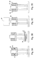
- Figures 3A to 3D illustrate various methods of generating heat at the contact area of the workpiece.
- Figure 3A shows an electrical heater 33 embedded in the tool body 26 near its end face. The heat is transmitted via the tool body, along the insert body to the contacting end face of the body rim.
- Figure 3B shows an induction heating coil 34 surrounding the lower end of the insert, for heating the insert.
- Figure 3C shows schematically an ultrasonic generator 35 for applying ultrasonic vibration to the tool body 26 and thus by transmission along the insert to the contact area of the workpiece.
- Figure 3D illustrates the low-amplitude rotational oscillation of the insert with respect to the workpiece by means of suitable movement of the tool 23, as indicated by the contra-arrows 36. The friction between the insert and the workpiece generates the heat.
- Figures 4A-4C illustrate a possible alternative external form for the example insert described above.
- the exterior of the body portion 37 is cylindrical in section, and the exterior of the collapsible portion 15 is formed with splines 38, which engage the workpiece around the hole to prevent relative rotation. When the collapsible part folds outwardly upon installation, the splines also engage the underneath face of the workpiece 22, as illustrated in Figures 4B and 4C .
- FIGs 5A to 5E illustrate an alternative form of fastener in the form of a blind rivet.
- This rivet ( Figure 5A ) is generally similar to the well-known HEMLOK (Registered Trade Mark) rivet. It comprises an elongated tubular shell 41, having an enlarged head 42 at one end. It also comprises an elongated mandrel 43 having an enlarged head 39 adjacent the tail end of the shell. The mandrel has a breakneck 44, in the appropriate place. The mandrel head 39 has a projecting rim 17, similar to that in the insert previously described.
- HEMLOK Registered Trade Mark
- FIGS 5B to 5E show the use of this rivet to secure a non-thermoplastic workpiece 45 to a thermoplastic workpiece 46.
- the workpiece 45 is provided with a preformed hole 47 to accommodate the rivet body.
- the forming of the hole in the thermoplastic workpiece 46, and the installation of the rivet to secure the workpieces together, are analogous to the process described above with reference to the insert.
- Figure 6 corresponds to Figure 5A , and shows an alternative arrangement in which the rim 17 is provided as part of the rivet shell, the mandrel head 48 being accommodated inside the rim.
- the application of heat may be continued for a sufficient time after the fastener has penetrated the workpiece and formed the hole.
- an alternative method of generating frictional heat at the contact area is by the continuous rotation of the fastener with respect to the thermoplastic workpiece.
- the underhead lugs 14 may be omitted, in cases where the hexagonal or splined shape of the body provides sufficient resistance to rotation of the fastener in the workpiece.
- the fastener head underside may be provided with a continuous annular projection which, on installation by the methods described above, enters the near face of the thermoplastic workpeice to provide a barrier to the ingress of fluid.
Landscapes
- Engineering & Computer Science (AREA)
- General Engineering & Computer Science (AREA)
- Mechanical Engineering (AREA)
- Lining Or Joining Of Plastics Or The Like (AREA)
- Insertion Pins And Rivets (AREA)
- Connection Of Plates (AREA)
- Slide Fasteners, Snap Fasteners, And Hook Fasteners (AREA)
- Dowels (AREA)
- Perforating, Stamping-Out Or Severing By Means Other Than Cutting (AREA)
Claims (18)
- Blindbefestigungselement (11) zum Einbau in ein thermoplastisches Werkstück, wobei das Blindbefestigungselement eine vordere Endfläche (21) aufweist, die im Wesentlichen eben und nicht schleifend ist und keine Bohrzähne aufweist, dadurch gekennzeichnet, dass die vordere Endfläche des Befestigungselementes durch die Endfläche eines nach vorne vorspringenden Kranzes (17, 19) gebildet ist, der eine Öffnung umgibt, wobei der nach vorne vorspringende Kranz eine Wandstärke aufweist, die klein ist, so dass im Gebrauch und wenn die vordere Endfläche des Befestigungselementes in Kontakt mit der nahe gelegenen Fläche des thermoplastischen Werkstückes gehalten wird und Wärme und Druck auf den Kontaktbereich des Werkstückes an dem vorderen Ende des Befestigungselementes aufgebracht wird, das Befestigungselement fortschreitend ein Loch durch das thermoplastische Werkstück bildet, wobei das Befestigungselement dann in dieses Loch eingebaut werden kann.
- Blindbefestigungselement nach Anspruch 1, bei dem die Öffnung so ausgebildet ist, dass sie den Pfropfen des Werkstück-Materials aufnimmt, der durch die vordere Endfläche gebildet wird.
- Blindbefestigungselement nach Anspruch 2, das Einrichtungen zum Verhindern eines Herausfallens des Stopfens aus dem vorderen Ende des Befestigungselementes einschließt, nachdem das letztere das Werkstück durchdrungen hat.
- Blindbefestigungselement nach Anspruch 3, bei dem der Kranz nach innen konvergiert, um auf diese Weise das Festhalten des Propfens innerhalb des Kranzes zu unterstützen.
- Blindbefestigungselement nach einem der vorhergehenden Ansprüche, das die Form eines Gewindeeinsatzes aufweist.
- Blindbefestigungselement nach Anspruch 5, das Einrichtungen für einen Eingriff mit dem Werkstück einschließt, wenn das Befestigungselement in diesem eingebaut ist, wodurch einer Drehung des eingebauten Befestigungselementes in seinem Loch Widerstand entgegengesetzt wird.
- Blindbefestigungselement nach einem der Ansprüche 1 bis 4, das die Form eines Blindniets aufweist.
- Blindbefestigungselement nach einem der vorhergehenden Ansprüche, das einen Innenkanal in Verbindung mit der Öffnung aufweist.
- Verfahren zur Bildung eines Loches in einem thermoplastischen Werkstück ohne dieses zu bohren, um ein Blindbefestigungselement in dieses einzubauen, dadurch gekennzeichnet, dass das Blindbefestigungselement eine vordere Endfläche aufweist, die im Wesentlichen eben und nicht schleifend ist und keine Bohrzähne aufweist, wobei die vordere Endfläche des Befestigungselementes durch die Endfläche eines nach vorne vorspringenden Kranzes gebildet ist, der eine Öffnung umgibt, wobei das Verfahren Folgendes umfasst:in Kontakt bringen der nahe gelegenen Fläche des Werkstückes mit dem vorderen Ende des Befestigungselementes, und Anwenden von Wärme und Druck auf die Kontaktbereiche des Werkstückes an dem vorderen Ende des Befestigungselementes, wobei der nach vorne vorspringende Kranz eine Wandstärke aufweist, die ausreichend klein ist, damit das Befestigungselement fortschreitend ein Loch durch das thermoplastische Werkstück bildet, wobei das Befestigungsmittel nachfolgend durch dieses Loch hindurch eingebaut werden kann.
- Verfahren nach Anspruch 9, bei dem die Wärme außerhalb des Befestigungselementes erzeugt wird.
- Verfahren nach Anspruch 10, bei dem die Wärme durch eine Wärmeerzeugungseinrichtung erzeugt wird, die mit einem Einbauwerkzeug verbunden ist, mit dem das Befestigungsmittel in Eingriff steht.
- Verfahren nach Anspruch 9, bei dem die Wärme durch eine Induktionsheizung des Befestigungselementes erzeugt wird.
- Verfahren nach Anspruch 9, bei dem die Wärme durch Reibung zwischen der vorderen Endfläche des Befestigungselementes und dem Kontaktbereich des Werkstückes erzeugt wird.
- Verfahren nach Anspruch 13, bei dem die Reibung durch eine eine geringe Amplitude aufweisende Drehschwingung des Befestigungselementes gegenüber dem Werkstück erzeugt wird.
- Verfahren nach Anspruch 13, bei dem die Reibung durch eine kontinuierliche Drehung des Befestigungselementes gegenüber dem Werkstück erzeugt wird.
- Verfahren nach Anspruch 9, bei dem die Wärme durch eine Ultraschallschwingung des Befestigungselementes erzeugt wird.
- Verfahren zur Bildung eines Loches in einen Werkstück, wobei dieses Verfahren so ist, wie es in einem der Ansprüche 9 bis 16 beansprucht ist, in Kombination mit dem nachfolgenden Schritt des Einbauens des Befestigungselementes in das so gebildete Loch.
- Verfahren zur Bildung eines Loches in einem Werkstück, wobei dieses Verfahren so ist, wie es im Anspruch 17 beansprucht ist, unter Einschluss des Schrittes des in Eingriff Bringens geeigneter Einrichtungen auf dem Befestigungselement mit dem thermoplastischen Werkstück mit Hilfe von Wärme, wodurch einer Drehung des eingebauten Befestigungselementes in seinem Loch Widerstand entgegengesetzt wird.
Applications Claiming Priority (2)
| Application Number | Priority Date | Filing Date | Title |
|---|---|---|---|
| GB0311270A GB2401661B (en) | 2003-05-16 | 2003-05-16 | Blind fastener and method of installation thereof |
| PCT/GB2004/001795 WO2004102015A1 (en) | 2003-05-16 | 2004-04-27 | Blind fastener and method of installation thereof |
Publications (2)
| Publication Number | Publication Date |
|---|---|
| EP1625309A1 EP1625309A1 (de) | 2006-02-15 |
| EP1625309B1 true EP1625309B1 (de) | 2009-02-04 |
Family
ID=9958205
Family Applications (1)
| Application Number | Title | Priority Date | Filing Date |
|---|---|---|---|
| EP04729672A Expired - Lifetime EP1625309B1 (de) | 2003-05-16 | 2004-04-27 | Blindniete und einsatz verfahren derselben |
Country Status (10)
| Country | Link |
|---|---|
| US (2) | US7645104B2 (de) |
| EP (1) | EP1625309B1 (de) |
| JP (2) | JP4546478B2 (de) |
| CN (1) | CN100395457C (de) |
| AT (1) | ATE422225T1 (de) |
| CA (1) | CA2515704A1 (de) |
| DE (1) | DE602004019334D1 (de) |
| ES (1) | ES2321193T3 (de) |
| GB (1) | GB2401661B (de) |
| WO (1) | WO2004102015A1 (de) |
Cited By (1)
| Publication number | Priority date | Publication date | Assignee | Title |
|---|---|---|---|---|
| DE102013103615A1 (de) | 2013-04-10 | 2014-10-30 | Dr. Ing. H.C. F. Porsche Aktiengesellschaft | Blindniet und Blindnietverbindung |
Families Citing this family (46)
| Publication number | Priority date | Publication date | Assignee | Title |
|---|---|---|---|---|
| GB2404231B (en) * | 2003-07-24 | 2006-09-06 | Newfrey Llc | Improved blind fastener and method of setting |
| US20060024145A1 (en) * | 2004-07-29 | 2006-02-02 | Pei-Chung Wang | Friction stir rivet and method of joining therewith |
| DE102004049045A1 (de) * | 2004-10-08 | 2006-04-20 | Fischerwerke Artur Fischer Gmbh & Co. Kg | Blindniete |
| US20060175381A1 (en) * | 2005-02-10 | 2006-08-10 | Pei-Chung Wang | Friction stir nut and method of joining therewith |
| US8707539B2 (en) | 2006-02-12 | 2014-04-29 | Wurth International Ag | Gun rivet |
| WO2007090681A2 (de) * | 2006-02-12 | 2007-08-16 | Adolf Würth GmbH & Co. KG | Blindniet und vorrichtung hierfür |
| DE202006013142U1 (de) | 2006-08-26 | 2006-11-16 | Textron Verbindungstechnik Gmbh & Co. Ohg | Selbstbohrendes Blindniet |
| DE102007040371A1 (de) * | 2007-08-20 | 2009-02-26 | Adolf Würth GmbH & Co. KG | Blindniet |
| US20110164945A1 (en) * | 2008-05-13 | 2011-07-07 | Co-Operative Research Centre For Advanced Automotive Technology Ltd. | Blind rivet and a method of joining therewith |
| JP5419482B2 (ja) * | 2009-02-05 | 2014-02-19 | 輝文 野地川 | 部材の穴を塞ぎ体で塞ぐ方法 |
| FR2953748B1 (fr) * | 2009-12-15 | 2012-03-09 | Bollhoff Otalu Sa | Insert a filetage interieur pour montage en aveugle en extremite de tube et procede de montage en aveugle |
| JP5508154B2 (ja) * | 2010-06-17 | 2014-05-28 | ポップリベット・ファスナー株式会社 | ブラインドファスナーおよびその製造方法 |
| US9309914B2 (en) * | 2010-07-07 | 2016-04-12 | Sherex Fastening Solutions, Llc | Low-profile rivet-like fastener |
| DE102011014819A1 (de) * | 2011-03-23 | 2012-09-27 | Airbus Operations Gmbh | Befestigungsvorrichtung und Verfahren zur Herstellung einer Befestigungsvorrichtung |
| FR2974606B1 (fr) * | 2011-04-29 | 2013-06-14 | Alex Grojean | Boulon a sertir en aveugle |
| DE102012001088A1 (de) * | 2012-01-20 | 2013-07-25 | Profil Verbindungstechnik Gmbh & Co. Kg | Zweiteiliges Mutterelement für Kunststoffbauteile |
| US9174263B2 (en) | 2012-05-23 | 2015-11-03 | Temper Ip, Llc | Tool and shell using induction heating |
| CN102829056B (zh) * | 2012-09-10 | 2015-08-12 | 湖南省金为型材有限公司 | 自钻攻铆紧固件 |
| CN102814794A (zh) * | 2012-09-10 | 2012-12-12 | 湖南省金为型材有限公司 | 钻铆紧固件 |
| CN102837298B (zh) * | 2012-09-10 | 2015-10-28 | 湖南省金为型材有限公司 | 用于钻铆紧固件的工具 |
| CN102814789B (zh) * | 2012-09-10 | 2015-10-28 | 湖南省金为型材有限公司 | 一种用于钻铆紧固件的工具 |
| US9555580B1 (en) | 2013-03-21 | 2017-01-31 | Temper Ip, Llc. | Friction stir welding fastener |
| WO2014171399A1 (ja) * | 2013-04-15 | 2014-10-23 | 富士フイルム株式会社 | 光学フィルム、光学フィルムの製造方法、偏光板、及び画像表示装置 |
| DE102013223005A1 (de) * | 2013-11-12 | 2015-05-13 | Brose Fahrzeugteile Gmbh & Co. Kg, Coburg | Verfahren zum Verbinden einer Buchse mit einem Bauteil |
| JP6111991B2 (ja) * | 2013-11-18 | 2017-04-12 | トヨタ紡織株式会社 | 金属ナット付き樹脂成形品 |
| US9656317B1 (en) | 2014-02-03 | 2017-05-23 | Temper Ip, Llc | Stamp, mold, quench of aluminum and magnesium sheet |
| US9808856B2 (en) * | 2014-09-25 | 2017-11-07 | GM Global Technology Operations LLC | Apparatus and methods for reducing corrosion of joining composite workpieces |
| CN104389876B (zh) * | 2014-11-25 | 2019-02-01 | 厦门宏发开关设备有限公司 | 简易的卡扣结构 |
| US20160201709A1 (en) * | 2015-01-13 | 2016-07-14 | GM Global Technology Operations LLC | Rivet with cutting mandrel tip and one-sided joining method |
| JP6785560B2 (ja) * | 2015-02-13 | 2020-11-18 | 三星ディスプレイ株式會社Samsung Display Co.,Ltd. | 締結部材、及びこれを対象物に固定する方法 |
| EP3280923B1 (de) * | 2015-04-10 | 2020-02-12 | R B & W Manufacturing LLC | Verfahren zur installation eines selbstschliessenden befestigungselements |
| FR3037369B1 (fr) * | 2015-06-11 | 2017-07-21 | Lisi Aerospace | Fixation installee d'un seul cote a douille deformable |
| WO2016205541A1 (en) * | 2015-06-16 | 2016-12-22 | The Regents Of The University Of Michigan | Fastener and method for joining dissimilar materials |
| US11293471B2 (en) | 2016-04-14 | 2022-04-05 | U.S. Farathane Corporation | Injection molded rivet-style fastener and housing with snap assembly functionality along with an injection molding process for producing such a rivet without an undercut feature |
| US20170298976A1 (en) | 2016-04-14 | 2017-10-19 | U.S. Farathane Corporation | Injection molded rivet-style fastener and housing with snap assembly functionality along with an injection molding process for producing such a rivet without an undercut feature |
| JP6806552B2 (ja) * | 2016-12-15 | 2021-01-06 | 矢崎総業株式会社 | 導電材の固定構造 |
| US10675671B2 (en) * | 2017-01-30 | 2020-06-09 | GM Global Technology Operations LLC | Blind flow screw joining of materials |
| CN107309618B (zh) * | 2017-06-19 | 2019-09-27 | 南京水门电子有限公司 | 水表玛瑙轴套的装配工艺方法 |
| US20190022737A1 (en) * | 2017-07-19 | 2019-01-24 | GM Global Technology Operations LLC | Friction stir blind rivet joining system and method |
| EP3575618B1 (de) * | 2018-05-30 | 2023-09-13 | Profil Verbindungstechnik GmbH & Co. KG | Selbststanzendes nietelement, zusammenbauteil bestehend aus dem nietelement und einem bauteil, verfahren zur herstellung des zusammenbauteils und matrize |
| DE102019113560A1 (de) | 2018-05-30 | 2019-12-05 | Profil Verbindungstechnik Gmbh & Co. Kg | Selbststanzendes Nietelement, Zusammenbauteil bestehend aus dem Nietelement und einem Bauteil, Verfahren zur Herstellung des Zusammenbauteils und Matrize |
| US11209040B2 (en) | 2019-07-15 | 2021-12-28 | Rb&W Manufacturing Llc | Self-clinching fastener |
| US11898588B2 (en) * | 2020-02-26 | 2024-02-13 | Caterpillar Inc. | Compactor tip with heated retention bolt |
| RU2735166C1 (ru) * | 2020-06-15 | 2020-10-28 | ОБЩЕСТВО С ОГРАНИЧЕННОЙ ОТВЕТСТВЕННОСТЬЮ "ИНЖЕНЕРНО-ТЕХНИЧЕСКИЙ ЦЕНТР "ФИКСИТ" (ООО "ИТЦ "Фиксит") | Заклепка герметичная |
| EP3926184B1 (de) * | 2020-06-15 | 2024-05-01 | BBA S.r.l. | Blindnietelement, insbesondere zur herstellung einer schraubverbindung in einem bauteil |
| US11913488B2 (en) | 2021-05-27 | 2024-02-27 | Rb&W Manufacturing Llc | Self-clinching and self-piercing construction element with multi-purpose pilot |
Family Cites Families (29)
| Publication number | Priority date | Publication date | Assignee | Title |
|---|---|---|---|---|
| US801358A (en) * | 1904-12-27 | 1905-10-10 | Butterick Publishing Co Ltd | Cutting or perforating tool. |
| US2122368A (en) * | 1936-11-21 | 1938-06-28 | Gen Tire & Rubber Co | Punch |
| US2188422A (en) * | 1937-06-09 | 1940-01-30 | Goodrich Co B F | Fluid-tight attachment and tubular rivet therefor |
| US3075573A (en) * | 1959-09-23 | 1963-01-29 | Continental Can Co | Apparatus for punching holes or cutouts in thermoplastic sheet material |
| US3215026A (en) * | 1965-03-10 | 1965-11-02 | John H Davis | Blind press nut devices |
| DE3109500A1 (de) * | 1981-03-12 | 1982-10-07 | Repa Feinstanzwerk Gmbh, 7071 Alfdorf | Verfahren und werkzeug zur plastischen verformung von durch druck und waerme verformbarem material |
| JPS5859033A (ja) * | 1981-10-05 | 1983-04-07 | Yamakawa Kogyo Kk | 樹脂部品におけるリベツトかしめ付け法 |
| JPS58196311A (ja) * | 1982-05-11 | 1983-11-15 | 阪村 芳一 | ブラインドナツトの締結方法とこれに使用されるブラインドナツトおよび締結用工具 |
| JPS621525A (ja) * | 1985-06-28 | 1987-01-07 | Sailor Pen Co Ltd | プラスチツク部品へのナツト植込方法 |
| JPS62162409U (de) * | 1986-04-04 | 1987-10-15 | ||
| DE3744450A1 (de) * | 1987-12-29 | 1989-07-13 | Boellhoff & Co | Blindniet |
| DE3824817A1 (de) * | 1988-07-21 | 1990-01-25 | Hilti Ag | Verfahren zum verbinden duenner bauteile und befestigungselementen hierzu |
| US4872935A (en) * | 1988-11-28 | 1989-10-10 | Forward Technology Industries, Inc. | Apparatus and method for bonding a plastic container and spout |
| DE3922684A1 (de) * | 1989-03-23 | 1991-01-24 | Jaeger Eberhard Gmbh | Loch- und gewindeformende schraube |
| US5060363A (en) * | 1990-09-12 | 1991-10-29 | Bj Automations, Inc. | Apparatus and method for forming holes in thermoplastic webbing |
| JP2769654B2 (ja) * | 1991-12-04 | 1998-06-25 | 株式会社国盛化学 | 板状体の固着方法 |
| GB2269873A (en) * | 1992-08-21 | 1994-02-23 | Avdel Systems Ltd | Self-plugging blind fastener |
| US5267386A (en) * | 1992-12-07 | 1993-12-07 | Ford Motor Company | Method of securing a member to a heat softenable material |
| JPH11270535A (ja) * | 1998-03-23 | 1999-10-05 | Pop Rivet Fastener Kk | 締結具 |
| GB2344864A (en) * | 1998-12-17 | 2000-06-21 | Textron Fastening Syst Ltd | Blind fastener |
| US6227433B1 (en) * | 2000-04-04 | 2001-05-08 | The Boeing Company | Friction welded fastener process |
| FR2815570B1 (fr) * | 2000-10-24 | 2003-08-08 | Faurecia Ind | Procede de fabrication d'une piece en matiere plastique, insert de fixation correspondant, et piece resultante |
| WO2002073045A2 (de) * | 2001-03-09 | 2002-09-19 | Newfrey Llc | Selbststanzender niet, verfahren und vorrichtung zum setzen eines nietelements und seine verwendung |
| DE10130681B4 (de) * | 2001-06-26 | 2006-10-12 | Reck Engineering Ingenieurbüro für Verbindungstechnik GmbH | Selbstbohrende Blindnietmutter |
| DE10241326A1 (de) | 2001-12-11 | 2004-03-18 | Newfrey Llc, Newark | Befestigungselement, insbesondere zum Blindnieten |
| JP2005537451A (ja) * | 2002-09-04 | 2005-12-08 | ニューフレイ リミテッド ライアビリティ カンパニー | 締結要素、特にブラインドリベット締結のための締結要素 |
| GB2392716B (en) * | 2002-09-09 | 2005-09-07 | Emhart Llc | Self-piercing blind fastener |
| US7171882B2 (en) * | 2003-10-15 | 2007-02-06 | Amros Industries, Inc. | Knife-like cutting die |
| US20060024145A1 (en) * | 2004-07-29 | 2006-02-02 | Pei-Chung Wang | Friction stir rivet and method of joining therewith |
-
2003
- 2003-05-16 GB GB0311270A patent/GB2401661B/en not_active Expired - Fee Related
-
2004
- 2004-04-27 ES ES04729672T patent/ES2321193T3/es not_active Expired - Lifetime
- 2004-04-27 CA CA002515704A patent/CA2515704A1/en not_active Abandoned
- 2004-04-27 CN CNB2004800118898A patent/CN100395457C/zh not_active Expired - Fee Related
- 2004-04-27 DE DE602004019334T patent/DE602004019334D1/de not_active Expired - Lifetime
- 2004-04-27 US US10/545,906 patent/US7645104B2/en not_active Expired - Lifetime
- 2004-04-27 EP EP04729672A patent/EP1625309B1/de not_active Expired - Lifetime
- 2004-04-27 AT AT04729672T patent/ATE422225T1/de not_active IP Right Cessation
- 2004-04-27 JP JP2006530471A patent/JP4546478B2/ja not_active Expired - Lifetime
- 2004-04-27 WO PCT/GB2004/001795 patent/WO2004102015A1/en active Application Filing
-
2008
- 2008-01-10 US US11/972,331 patent/US7739782B2/en not_active Expired - Fee Related
-
2009
- 2009-09-24 JP JP2009218636A patent/JP2010019422A/ja active Pending
Cited By (1)
| Publication number | Priority date | Publication date | Assignee | Title |
|---|---|---|---|---|
| DE102013103615A1 (de) | 2013-04-10 | 2014-10-30 | Dr. Ing. H.C. F. Porsche Aktiengesellschaft | Blindniet und Blindnietverbindung |
Also Published As
| Publication number | Publication date |
|---|---|
| CA2515704A1 (en) | 2004-11-25 |
| CN100395457C (zh) | 2008-06-18 |
| US7645104B2 (en) | 2010-01-12 |
| GB2401661B (en) | 2006-03-29 |
| JP2010019422A (ja) | 2010-01-28 |
| US20080107499A1 (en) | 2008-05-08 |
| JP2006529021A (ja) | 2006-12-28 |
| WO2004102015A1 (en) | 2004-11-25 |
| CN1784551A (zh) | 2006-06-07 |
| US7739782B2 (en) | 2010-06-22 |
| GB0311270D0 (en) | 2003-06-18 |
| JP4546478B2 (ja) | 2010-09-15 |
| EP1625309A1 (de) | 2006-02-15 |
| US20060251489A1 (en) | 2006-11-09 |
| GB2401661A (en) | 2004-11-17 |
| ES2321193T3 (es) | 2009-06-03 |
| DE602004019334D1 (de) | 2009-03-19 |
| ATE422225T1 (de) | 2009-02-15 |
Similar Documents
| Publication | Publication Date | Title |
|---|---|---|
| EP1625309B1 (de) | Blindniete und einsatz verfahren derselben | |
| EP1635994B1 (de) | Blindniet und nasenanordnung zur installation des blindniets | |
| AU770215B2 (en) | Insert and method of installation thereof | |
| US3515028A (en) | Blind fastener | |
| EP1623126B1 (de) | Blindbefestiger und verfahren zur dessen entfernung von einem werkstück | |
| MXPA01005668A (es) | Sujetador ciego. | |
| JP2007527487A (ja) | 自己穿設式アンカー | |
| WO1987000892A1 (en) | A fastening system including a pull type fastener | |
| JP2013502551A (ja) | ブラインドリベット | |
| WO2005017369A3 (en) | Locator stud and method of assembly | |
| EP2540413B1 (de) | Entnietverfahren | |
| EP0556993B1 (de) | Blindniet | |
| WO1986004965A1 (en) | Fastening system and fastener for shipping containers and the like | |
| US4157675A (en) | Filled breakneck fastener | |
| EP1648634A1 (de) | Verbesserter blindniet und setzverfahren | |
| EP0728950A1 (de) | Verfahren zum Verbinden von zwei Bauteilen und Befestigungsvorrichtung dafür | |
| WO2003033918A2 (en) | Blind fasteners and installation methods and apparatus | |
| CN118525154A (zh) | 紧固系统和用于在基底中装配的方法 | |
| JPH0861339A (ja) | ブラインドリベット組立体 | |
| AU668913B2 (en) | Masonry anchors | |
| EP2644909A1 (de) | Niethülse, Blindnietanordnung und Verfahren zum Lösen desselben |
Legal Events
| Date | Code | Title | Description |
|---|---|---|---|
| PUAI | Public reference made under article 153(3) epc to a published international application that has entered the european phase |
Free format text: ORIGINAL CODE: 0009012 |
|
| 17P | Request for examination filed |
Effective date: 20050808 |
|
| AK | Designated contracting states |
Kind code of ref document: A1 Designated state(s): AT BE BG CH CY CZ DE DK EE ES FI FR GB GR HU IE IT LI LU MC NL PL PT RO SE SI SK TR |
|
| DAX | Request for extension of the european patent (deleted) | ||
| RAP1 | Party data changed (applicant data changed or rights of an application transferred) |
Owner name: AVDEL UK LIMITED |
|
| 17Q | First examination report despatched |
Effective date: 20080724 |
|
| GRAP | Despatch of communication of intention to grant a patent |
Free format text: ORIGINAL CODE: EPIDOSNIGR1 |
|
| GRAS | Grant fee paid |
Free format text: ORIGINAL CODE: EPIDOSNIGR3 |
|
| GRAA | (expected) grant |
Free format text: ORIGINAL CODE: 0009210 |
|
| AK | Designated contracting states |
Kind code of ref document: B1 Designated state(s): AT BE BG CH CY CZ DE DK EE ES FI FR GB GR HU IE IT LI LU MC NL PL PT RO SE SI SK TR |
|
| REG | Reference to a national code |
Ref country code: GB Ref legal event code: FG4D |
|
| REG | Reference to a national code |
Ref country code: CH Ref legal event code: EP |
|
| REG | Reference to a national code |
Ref country code: IE Ref legal event code: FG4D |
|
| REF | Corresponds to: |
Ref document number: 602004019334 Country of ref document: DE Date of ref document: 20090319 Kind code of ref document: P |
|
| REG | Reference to a national code |
Ref country code: ES Ref legal event code: FG2A Ref document number: 2321193 Country of ref document: ES Kind code of ref document: T3 |
|
| NLV1 | Nl: lapsed or annulled due to failure to fulfill the requirements of art. 29p and 29m of the patents act | ||
| PG25 | Lapsed in a contracting state [announced via postgrant information from national office to epo] |
Ref country code: FI Free format text: LAPSE BECAUSE OF FAILURE TO SUBMIT A TRANSLATION OF THE DESCRIPTION OR TO PAY THE FEE WITHIN THE PRESCRIBED TIME-LIMIT Effective date: 20090204 Ref country code: NL Free format text: LAPSE BECAUSE OF FAILURE TO SUBMIT A TRANSLATION OF THE DESCRIPTION OR TO PAY THE FEE WITHIN THE PRESCRIBED TIME-LIMIT Effective date: 20090204 Ref country code: SI Free format text: LAPSE BECAUSE OF FAILURE TO SUBMIT A TRANSLATION OF THE DESCRIPTION OR TO PAY THE FEE WITHIN THE PRESCRIBED TIME-LIMIT Effective date: 20090204 |
|
| PG25 | Lapsed in a contracting state [announced via postgrant information from national office to epo] |
Ref country code: PL Free format text: LAPSE BECAUSE OF FAILURE TO SUBMIT A TRANSLATION OF THE DESCRIPTION OR TO PAY THE FEE WITHIN THE PRESCRIBED TIME-LIMIT Effective date: 20090204 Ref country code: SE Free format text: LAPSE BECAUSE OF FAILURE TO SUBMIT A TRANSLATION OF THE DESCRIPTION OR TO PAY THE FEE WITHIN THE PRESCRIBED TIME-LIMIT Effective date: 20090504 Ref country code: AT Free format text: LAPSE BECAUSE OF FAILURE TO SUBMIT A TRANSLATION OF THE DESCRIPTION OR TO PAY THE FEE WITHIN THE PRESCRIBED TIME-LIMIT Effective date: 20090204 |
|
| PG25 | Lapsed in a contracting state [announced via postgrant information from national office to epo] |
Ref country code: BE Free format text: LAPSE BECAUSE OF FAILURE TO SUBMIT A TRANSLATION OF THE DESCRIPTION OR TO PAY THE FEE WITHIN THE PRESCRIBED TIME-LIMIT Effective date: 20090204 |
|
| PG25 | Lapsed in a contracting state [announced via postgrant information from national office to epo] |
Ref country code: CZ Free format text: LAPSE BECAUSE OF FAILURE TO SUBMIT A TRANSLATION OF THE DESCRIPTION OR TO PAY THE FEE WITHIN THE PRESCRIBED TIME-LIMIT Effective date: 20090204 Ref country code: EE Free format text: LAPSE BECAUSE OF FAILURE TO SUBMIT A TRANSLATION OF THE DESCRIPTION OR TO PAY THE FEE WITHIN THE PRESCRIBED TIME-LIMIT Effective date: 20090204 Ref country code: PT Free format text: LAPSE BECAUSE OF FAILURE TO SUBMIT A TRANSLATION OF THE DESCRIPTION OR TO PAY THE FEE WITHIN THE PRESCRIBED TIME-LIMIT Effective date: 20090706 Ref country code: DK Free format text: LAPSE BECAUSE OF FAILURE TO SUBMIT A TRANSLATION OF THE DESCRIPTION OR TO PAY THE FEE WITHIN THE PRESCRIBED TIME-LIMIT Effective date: 20090204 |
|
| PG25 | Lapsed in a contracting state [announced via postgrant information from national office to epo] |
Ref country code: SK Free format text: LAPSE BECAUSE OF FAILURE TO SUBMIT A TRANSLATION OF THE DESCRIPTION OR TO PAY THE FEE WITHIN THE PRESCRIBED TIME-LIMIT Effective date: 20090204 Ref country code: RO Free format text: LAPSE BECAUSE OF FAILURE TO SUBMIT A TRANSLATION OF THE DESCRIPTION OR TO PAY THE FEE WITHIN THE PRESCRIBED TIME-LIMIT Effective date: 20090204 |
|
| REG | Reference to a national code |
Ref country code: CH Ref legal event code: PL |
|
| PLBE | No opposition filed within time limit |
Free format text: ORIGINAL CODE: 0009261 |
|
| STAA | Information on the status of an ep patent application or granted ep patent |
Free format text: STATUS: NO OPPOSITION FILED WITHIN TIME LIMIT |
|
| 26N | No opposition filed |
Effective date: 20091105 |
|
| PG25 | Lapsed in a contracting state [announced via postgrant information from national office to epo] |
Ref country code: CH Free format text: LAPSE BECAUSE OF NON-PAYMENT OF DUE FEES Effective date: 20090430 Ref country code: BG Free format text: LAPSE BECAUSE OF FAILURE TO SUBMIT A TRANSLATION OF THE DESCRIPTION OR TO PAY THE FEE WITHIN THE PRESCRIBED TIME-LIMIT Effective date: 20090504 Ref country code: LI Free format text: LAPSE BECAUSE OF NON-PAYMENT OF DUE FEES Effective date: 20090430 |
|
| REG | Reference to a national code |
Ref country code: IE Ref legal event code: MM4A |
|
| PG25 | Lapsed in a contracting state [announced via postgrant information from national office to epo] |
Ref country code: MC Free format text: LAPSE BECAUSE OF NON-PAYMENT OF DUE FEES Effective date: 20090430 Ref country code: IE Free format text: LAPSE BECAUSE OF NON-PAYMENT OF DUE FEES Effective date: 20090427 |
|
| PG25 | Lapsed in a contracting state [announced via postgrant information from national office to epo] |
Ref country code: GR Free format text: LAPSE BECAUSE OF FAILURE TO SUBMIT A TRANSLATION OF THE DESCRIPTION OR TO PAY THE FEE WITHIN THE PRESCRIBED TIME-LIMIT Effective date: 20090505 |
|
| PG25 | Lapsed in a contracting state [announced via postgrant information from national office to epo] |
Ref country code: LU Free format text: LAPSE BECAUSE OF NON-PAYMENT OF DUE FEES Effective date: 20090427 |
|
| PG25 | Lapsed in a contracting state [announced via postgrant information from national office to epo] |
Ref country code: HU Free format text: LAPSE BECAUSE OF FAILURE TO SUBMIT A TRANSLATION OF THE DESCRIPTION OR TO PAY THE FEE WITHIN THE PRESCRIBED TIME-LIMIT Effective date: 20090805 |
|
| PGFP | Annual fee paid to national office [announced via postgrant information from national office to epo] |
Ref country code: ES Payment date: 20110518 Year of fee payment: 8 Ref country code: FR Payment date: 20110426 Year of fee payment: 8 |
|
| PG25 | Lapsed in a contracting state [announced via postgrant information from national office to epo] |
Ref country code: TR Free format text: LAPSE BECAUSE OF FAILURE TO SUBMIT A TRANSLATION OF THE DESCRIPTION OR TO PAY THE FEE WITHIN THE PRESCRIBED TIME-LIMIT Effective date: 20090204 |
|
| PG25 | Lapsed in a contracting state [announced via postgrant information from national office to epo] |
Ref country code: CY Free format text: LAPSE BECAUSE OF FAILURE TO SUBMIT A TRANSLATION OF THE DESCRIPTION OR TO PAY THE FEE WITHIN THE PRESCRIBED TIME-LIMIT Effective date: 20090204 |
|
| PGFP | Annual fee paid to national office [announced via postgrant information from national office to epo] |
Ref country code: IT Payment date: 20110414 Year of fee payment: 8 |
|
| REG | Reference to a national code |
Ref country code: FR Ref legal event code: ST Effective date: 20121228 |
|
| PG25 | Lapsed in a contracting state [announced via postgrant information from national office to epo] |
Ref country code: FR Free format text: LAPSE BECAUSE OF NON-PAYMENT OF DUE FEES Effective date: 20120430 Ref country code: IT Free format text: LAPSE BECAUSE OF NON-PAYMENT OF DUE FEES Effective date: 20120427 |
|
| REG | Reference to a national code |
Ref country code: ES Ref legal event code: FD2A Effective date: 20130715 |
|
| PG25 | Lapsed in a contracting state [announced via postgrant information from national office to epo] |
Ref country code: ES Free format text: LAPSE BECAUSE OF NON-PAYMENT OF DUE FEES Effective date: 20120428 |
|
| PGFP | Annual fee paid to national office [announced via postgrant information from national office to epo] |
Ref country code: GB Payment date: 20210331 Year of fee payment: 18 |
|
| PGFP | Annual fee paid to national office [announced via postgrant information from national office to epo] |
Ref country code: DE Payment date: 20210330 Year of fee payment: 18 |
|
| REG | Reference to a national code |
Ref country code: DE Ref legal event code: R119 Ref document number: 602004019334 Country of ref document: DE |
|
| GBPC | Gb: european patent ceased through non-payment of renewal fee |
Effective date: 20220427 |
|
| PG25 | Lapsed in a contracting state [announced via postgrant information from national office to epo] |
Ref country code: GB Free format text: LAPSE BECAUSE OF NON-PAYMENT OF DUE FEES Effective date: 20220427 Ref country code: DE Free format text: LAPSE BECAUSE OF NON-PAYMENT OF DUE FEES Effective date: 20221103 |