EP1624667A2 - Beleuchtungs-Gerät mit Benutzung von Lichtleitern - Google Patents
Beleuchtungs-Gerät mit Benutzung von Lichtleitern Download PDFInfo
- Publication number
- EP1624667A2 EP1624667A2 EP05077439A EP05077439A EP1624667A2 EP 1624667 A2 EP1624667 A2 EP 1624667A2 EP 05077439 A EP05077439 A EP 05077439A EP 05077439 A EP05077439 A EP 05077439A EP 1624667 A2 EP1624667 A2 EP 1624667A2
- Authority
- EP
- European Patent Office
- Prior art keywords
- light
- light guide
- illumination apparatus
- longitudinal direction
- diffuser
- Prior art date
- Legal status (The legal status is an assumption and is not a legal conclusion. Google has not performed a legal analysis and makes no representation as to the accuracy of the status listed.)
- Withdrawn
Links
Images


Classifications
-
- H—ELECTRICITY
- H04—ELECTRIC COMMUNICATION TECHNIQUE
- H04N—PICTORIAL COMMUNICATION, e.g. TELEVISION
- H04N1/00—Scanning, transmission or reproduction of documents or the like, e.g. facsimile transmission; Details thereof
- H04N1/024—Details of scanning heads ; Means for illuminating the original
- H04N1/028—Details of scanning heads ; Means for illuminating the original for picture information pick-up
- H04N1/02815—Means for illuminating the original, not specific to a particular type of pick-up head
- H04N1/02885—Means for compensating spatially uneven illumination, e.g. an aperture arrangement
-
- G—PHYSICS
- G02—OPTICS
- G02B—OPTICAL ELEMENTS, SYSTEMS OR APPARATUS
- G02B6/00—Light guides; Structural details of arrangements comprising light guides and other optical elements, e.g. couplings
-
- H—ELECTRICITY
- H04—ELECTRIC COMMUNICATION TECHNIQUE
- H04N—PICTORIAL COMMUNICATION, e.g. TELEVISION
- H04N1/00—Scanning, transmission or reproduction of documents or the like, e.g. facsimile transmission; Details thereof
- H04N1/024—Details of scanning heads ; Means for illuminating the original
- H04N1/028—Details of scanning heads ; Means for illuminating the original for picture information pick-up
- H04N1/02815—Means for illuminating the original, not specific to a particular type of pick-up head
- H04N1/0282—Using a single or a few point light sources, e.g. a laser diode
- H04N1/02835—Using a single or a few point light sources, e.g. a laser diode in combination with a light guide, e.g. optical fibre, glass plate
-
- H—ELECTRICITY
- H04—ELECTRIC COMMUNICATION TECHNIQUE
- H04N—PICTORIAL COMMUNICATION, e.g. TELEVISION
- H04N1/00—Scanning, transmission or reproduction of documents or the like, e.g. facsimile transmission; Details thereof
- H04N1/024—Details of scanning heads ; Means for illuminating the original
- H04N1/028—Details of scanning heads ; Means for illuminating the original for picture information pick-up
- H04N1/02815—Means for illuminating the original, not specific to a particular type of pick-up head
- H04N1/0282—Using a single or a few point light sources, e.g. a laser diode
- H04N1/0284—Using a single or a few point light sources, e.g. a laser diode in combination with a light integrating, concentrating or diffusing cavity
-
- H—ELECTRICITY
- H04—ELECTRIC COMMUNICATION TECHNIQUE
- H04N—PICTORIAL COMMUNICATION, e.g. TELEVISION
- H04N1/00—Scanning, transmission or reproduction of documents or the like, e.g. facsimile transmission; Details thereof
- H04N1/024—Details of scanning heads ; Means for illuminating the original
- H04N1/028—Details of scanning heads ; Means for illuminating the original for picture information pick-up
- H04N1/03—Details of scanning heads ; Means for illuminating the original for picture information pick-up with photodetectors arranged in a substantially linear array
- H04N1/031—Details of scanning heads ; Means for illuminating the original for picture information pick-up with photodetectors arranged in a substantially linear array the photodetectors having a one-to-one and optically positive correspondence with the scanned picture elements, e.g. linear contact sensors
- H04N1/0315—Details of scanning heads ; Means for illuminating the original for picture information pick-up with photodetectors arranged in a substantially linear array the photodetectors having a one-to-one and optically positive correspondence with the scanned picture elements, e.g. linear contact sensors using photodetectors and illumination means mounted on separate supports or substrates or mounted in different planes
-
- H—ELECTRICITY
- H04—ELECTRIC COMMUNICATION TECHNIQUE
- H04N—PICTORIAL COMMUNICATION, e.g. TELEVISION
- H04N1/00—Scanning, transmission or reproduction of documents or the like, e.g. facsimile transmission; Details thereof
- H04N1/024—Details of scanning heads ; Means for illuminating the original
- H04N1/028—Details of scanning heads ; Means for illuminating the original for picture information pick-up
- H04N1/03—Details of scanning heads ; Means for illuminating the original for picture information pick-up with photodetectors arranged in a substantially linear array
- H04N1/031—Details of scanning heads ; Means for illuminating the original for picture information pick-up with photodetectors arranged in a substantially linear array the photodetectors having a one-to-one and optically positive correspondence with the scanned picture elements, e.g. linear contact sensors
- H04N1/0318—Integral pick-up heads, i.e. self-contained heads whose basic elements are a light-source, a lens array and a photodetector array which are supported by a single-piece frame
-
- H—ELECTRICITY
- H04—ELECTRIC COMMUNICATION TECHNIQUE
- H04N—PICTORIAL COMMUNICATION, e.g. TELEVISION
- H04N1/00—Scanning, transmission or reproduction of documents or the like, e.g. facsimile transmission; Details thereof
- H04N1/46—Colour picture communication systems
- H04N1/48—Picture signal generators
- H04N1/482—Picture signal generators using the same detector device sequentially for different colour components
- H04N1/484—Picture signal generators using the same detector device sequentially for different colour components with sequential colour illumination of the original
-
- H—ELECTRICITY
- H04—ELECTRIC COMMUNICATION TECHNIQUE
- H04N—PICTORIAL COMMUNICATION, e.g. TELEVISION
- H04N1/00—Scanning, transmission or reproduction of documents or the like, e.g. facsimile transmission; Details thereof
- H04N1/04—Scanning arrangements, i.e. arrangements for the displacement of active reading or reproducing elements relative to the original or reproducing medium, or vice versa
- H04N1/10—Scanning arrangements, i.e. arrangements for the displacement of active reading or reproducing elements relative to the original or reproducing medium, or vice versa using flat picture-bearing surfaces
- H04N1/1013—Scanning arrangements, i.e. arrangements for the displacement of active reading or reproducing elements relative to the original or reproducing medium, or vice versa using flat picture-bearing surfaces with sub-scanning by translatory movement of at least a part of the main-scanning components
- H04N1/1017—Scanning arrangements, i.e. arrangements for the displacement of active reading or reproducing elements relative to the original or reproducing medium, or vice versa using flat picture-bearing surfaces with sub-scanning by translatory movement of at least a part of the main-scanning components the main-scanning components remaining positionally invariant with respect to one another in the sub-scanning direction
-
- H—ELECTRICITY
- H04—ELECTRIC COMMUNICATION TECHNIQUE
- H04N—PICTORIAL COMMUNICATION, e.g. TELEVISION
- H04N1/00—Scanning, transmission or reproduction of documents or the like, e.g. facsimile transmission; Details thereof
- H04N1/04—Scanning arrangements, i.e. arrangements for the displacement of active reading or reproducing elements relative to the original or reproducing medium, or vice versa
- H04N1/19—Scanning arrangements, i.e. arrangements for the displacement of active reading or reproducing elements relative to the original or reproducing medium, or vice versa using multi-element arrays
- H04N1/191—Scanning arrangements, i.e. arrangements for the displacement of active reading or reproducing elements relative to the original or reproducing medium, or vice versa using multi-element arrays the array comprising a one-dimensional array, or a combination of one-dimensional arrays, or a substantially one-dimensional array, e.g. an array of staggered elements
- H04N1/192—Simultaneously or substantially simultaneously scanning picture elements on one main scanning line
- H04N1/193—Simultaneously or substantially simultaneously scanning picture elements on one main scanning line using electrically scanned linear arrays, e.g. linear CCD arrays
-
- H—ELECTRICITY
- H04—ELECTRIC COMMUNICATION TECHNIQUE
- H04N—PICTORIAL COMMUNICATION, e.g. TELEVISION
- H04N2201/00—Indexing scheme relating to scanning, transmission or reproduction of documents or the like, and to details thereof
- H04N2201/024—Indexing scheme relating to scanning, transmission or reproduction of documents or the like, and to details thereof deleted
- H04N2201/028—Indexing scheme relating to scanning, transmission or reproduction of documents or the like, and to details thereof deleted for picture information pick-up
- H04N2201/03—Indexing scheme relating to scanning, transmission or reproduction of documents or the like, and to details thereof deleted for picture information pick-up deleted
- H04N2201/031—Indexing scheme relating to scanning, transmission or reproduction of documents or the like, and to details thereof deleted for picture information pick-up deleted deleted
- H04N2201/03104—Integral pick-up heads, i.e. self-contained heads whose basic elements are a light source, a lens and a photodetector supported by a single-piece frame
- H04N2201/03108—Components of integral heads
- H04N2201/03112—Light source
-
- H—ELECTRICITY
- H04—ELECTRIC COMMUNICATION TECHNIQUE
- H04N—PICTORIAL COMMUNICATION, e.g. TELEVISION
- H04N2201/00—Indexing scheme relating to scanning, transmission or reproduction of documents or the like, and to details thereof
- H04N2201/024—Indexing scheme relating to scanning, transmission or reproduction of documents or the like, and to details thereof deleted
- H04N2201/028—Indexing scheme relating to scanning, transmission or reproduction of documents or the like, and to details thereof deleted for picture information pick-up
- H04N2201/03—Indexing scheme relating to scanning, transmission or reproduction of documents or the like, and to details thereof deleted for picture information pick-up deleted
- H04N2201/031—Indexing scheme relating to scanning, transmission or reproduction of documents or the like, and to details thereof deleted for picture information pick-up deleted deleted
- H04N2201/03104—Integral pick-up heads, i.e. self-contained heads whose basic elements are a light source, a lens and a photodetector supported by a single-piece frame
- H04N2201/03108—Components of integral heads
- H04N2201/0312—Reflecting element upstream of the scanned picture elements
-
- H—ELECTRICITY
- H04—ELECTRIC COMMUNICATION TECHNIQUE
- H04N—PICTORIAL COMMUNICATION, e.g. TELEVISION
- H04N2201/00—Indexing scheme relating to scanning, transmission or reproduction of documents or the like, and to details thereof
- H04N2201/024—Indexing scheme relating to scanning, transmission or reproduction of documents or the like, and to details thereof deleted
- H04N2201/028—Indexing scheme relating to scanning, transmission or reproduction of documents or the like, and to details thereof deleted for picture information pick-up
- H04N2201/03—Indexing scheme relating to scanning, transmission or reproduction of documents or the like, and to details thereof deleted for picture information pick-up deleted
- H04N2201/031—Indexing scheme relating to scanning, transmission or reproduction of documents or the like, and to details thereof deleted for picture information pick-up deleted deleted
- H04N2201/03104—Integral pick-up heads, i.e. self-contained heads whose basic elements are a light source, a lens and a photodetector supported by a single-piece frame
- H04N2201/03108—Components of integral heads
- H04N2201/03125—Light guide upstream of the scanned picture elements
-
- H—ELECTRICITY
- H04—ELECTRIC COMMUNICATION TECHNIQUE
- H04N—PICTORIAL COMMUNICATION, e.g. TELEVISION
- H04N2201/00—Indexing scheme relating to scanning, transmission or reproduction of documents or the like, and to details thereof
- H04N2201/024—Indexing scheme relating to scanning, transmission or reproduction of documents or the like, and to details thereof deleted
- H04N2201/028—Indexing scheme relating to scanning, transmission or reproduction of documents or the like, and to details thereof deleted for picture information pick-up
- H04N2201/03—Indexing scheme relating to scanning, transmission or reproduction of documents or the like, and to details thereof deleted for picture information pick-up deleted
- H04N2201/031—Indexing scheme relating to scanning, transmission or reproduction of documents or the like, and to details thereof deleted for picture information pick-up deleted deleted
- H04N2201/03104—Integral pick-up heads, i.e. self-contained heads whose basic elements are a light source, a lens and a photodetector supported by a single-piece frame
- H04N2201/03108—Components of integral heads
- H04N2201/03141—Photodetector lens
-
- H—ELECTRICITY
- H04—ELECTRIC COMMUNICATION TECHNIQUE
- H04N—PICTORIAL COMMUNICATION, e.g. TELEVISION
- H04N2201/00—Indexing scheme relating to scanning, transmission or reproduction of documents or the like, and to details thereof
- H04N2201/024—Indexing scheme relating to scanning, transmission or reproduction of documents or the like, and to details thereof deleted
- H04N2201/028—Indexing scheme relating to scanning, transmission or reproduction of documents or the like, and to details thereof deleted for picture information pick-up
- H04N2201/03—Indexing scheme relating to scanning, transmission or reproduction of documents or the like, and to details thereof deleted for picture information pick-up deleted
- H04N2201/031—Indexing scheme relating to scanning, transmission or reproduction of documents or the like, and to details thereof deleted for picture information pick-up deleted deleted
- H04N2201/03104—Integral pick-up heads, i.e. self-contained heads whose basic elements are a light source, a lens and a photodetector supported by a single-piece frame
- H04N2201/03108—Components of integral heads
- H04N2201/03145—Photodetector
-
- H—ELECTRICITY
- H04—ELECTRIC COMMUNICATION TECHNIQUE
- H04N—PICTORIAL COMMUNICATION, e.g. TELEVISION
- H04N2201/00—Indexing scheme relating to scanning, transmission or reproduction of documents or the like, and to details thereof
- H04N2201/024—Indexing scheme relating to scanning, transmission or reproduction of documents or the like, and to details thereof deleted
- H04N2201/028—Indexing scheme relating to scanning, transmission or reproduction of documents or the like, and to details thereof deleted for picture information pick-up
- H04N2201/03—Indexing scheme relating to scanning, transmission or reproduction of documents or the like, and to details thereof deleted for picture information pick-up deleted
- H04N2201/031—Indexing scheme relating to scanning, transmission or reproduction of documents or the like, and to details thereof deleted for picture information pick-up deleted deleted
- H04N2201/03104—Integral pick-up heads, i.e. self-contained heads whose basic elements are a light source, a lens and a photodetector supported by a single-piece frame
- H04N2201/0315—Details of integral heads not otherwise provided for
- H04N2201/0317—Shape
-
- H—ELECTRICITY
- H04—ELECTRIC COMMUNICATION TECHNIQUE
- H04N—PICTORIAL COMMUNICATION, e.g. TELEVISION
- H04N2201/00—Indexing scheme relating to scanning, transmission or reproduction of documents or the like, and to details thereof
- H04N2201/024—Indexing scheme relating to scanning, transmission or reproduction of documents or the like, and to details thereof deleted
- H04N2201/028—Indexing scheme relating to scanning, transmission or reproduction of documents or the like, and to details thereof deleted for picture information pick-up
- H04N2201/03—Indexing scheme relating to scanning, transmission or reproduction of documents or the like, and to details thereof deleted for picture information pick-up deleted
- H04N2201/031—Indexing scheme relating to scanning, transmission or reproduction of documents or the like, and to details thereof deleted for picture information pick-up deleted deleted
- H04N2201/03104—Integral pick-up heads, i.e. self-contained heads whose basic elements are a light source, a lens and a photodetector supported by a single-piece frame
- H04N2201/0315—Details of integral heads not otherwise provided for
- H04N2201/03187—Additional optical element
-
- H—ELECTRICITY
- H04—ELECTRIC COMMUNICATION TECHNIQUE
- H04N—PICTORIAL COMMUNICATION, e.g. TELEVISION
- H04N2201/00—Indexing scheme relating to scanning, transmission or reproduction of documents or the like, and to details thereof
- H04N2201/024—Indexing scheme relating to scanning, transmission or reproduction of documents or the like, and to details thereof deleted
- H04N2201/028—Indexing scheme relating to scanning, transmission or reproduction of documents or the like, and to details thereof deleted for picture information pick-up
- H04N2201/03—Indexing scheme relating to scanning, transmission or reproduction of documents or the like, and to details thereof deleted for picture information pick-up deleted
- H04N2201/031—Indexing scheme relating to scanning, transmission or reproduction of documents or the like, and to details thereof deleted for picture information pick-up deleted deleted
- H04N2201/03104—Integral pick-up heads, i.e. self-contained heads whose basic elements are a light source, a lens and a photodetector supported by a single-piece frame
- H04N2201/0315—Details of integral heads not otherwise provided for
- H04N2201/03195—Coating, e.g. light adsorbing layer
Definitions
- the present invention relates to an illumination apparatus using a light guide.
- a contact type image sensor which contacts with an original and scans the original to read an image.
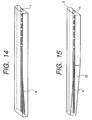
- One example of an illumination apparatus for use in such contact type image sensor is shown in Figs. 18, 19 and 20.
- Fig. 18 is a perspective view
- Fig. 19 is a sectional view
- Fig. 20 is a view of an end surface viewed from a longitudinal direction.
- a light emitting element 1 such as LED as a light source disposed on an end surface 12 of a light guide 2
- a part of the light guide 2 is provided with a diffusing surface 4 for diffusing and/or reflecting the light incident along the longitudinal direction.
- the diffusing surface 4 when the light repeatedly reflected by the inner face in the longitudinal direction is incident upon the diffusing surface 4, the incident light is scattered, a part of the light radiates from a radiating surface 13 of the light guide 2, and contributes to the illumination of the original as illumination light.
- the illuminance of the vicinity of the light emitting element is higher than that of other areas, and a problem arises that nonuniformity is caused in the illuminance of the longitudinal direction of the light guide.
- the light radiated from the light source 1 constituted of the light emitting elements such as LED disposed on the end surface of the light guide 2 is incident upon the inside of the light guide 2, repeatedly reflected by the inner face of the light guide 2 and thereby guided in the longitudinal direction of the light guide 2.
- a part of the light guide 2 is provided with the diffusing surface 4 along the longitudinal direction, the light repeatedly reflected by the inner face in the longitudinal direction is scattered upon incidence on the diffusing surface 4, and a part of the light contributes as the illumination light to illuminate the original.
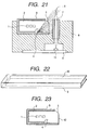
- a light guide cover 3 as shown in Fig. 22 is disposed outside the light guide 2 to enhance the light utilization efficiency, and attached so as to cover the light guide via an air layer so that the light leaking from the light guide 2 in a direction different from the original irradiation direction is returned into the light guide.
- the light guide cover 3 is formed, for example, of a white material with high light reflecting properties.
- An original (not shown) positioned on a read line 6 is irradiated with the light radiated from a radiating surface 5 (the surface of the light guide 2 radiating the light which contributes to the lighting of the original as the object to be illuminated) of the light guide 2 in an opening 16 of the light guide cover 3, and the reflected light is formed into an image by a rod lens array 7 on a line sensor 11 disposed on a sensor array 9.
- the line sensor 11 converts the information of the light formed into the image to an electric signal and outputs the signal, the reading of the original is carried out.
- Fig. 23 is a view only showing the light guide 2 having LED 1 in its end portion and the light guide cover 3. Since the light guide cover 3 covering the light guide 2 is manufactured mainly by injection molding, one side in a metal mold extracting direction forms an opening to extract the metal mold. Therefore, the opening of the light guide cover 3 is larger than the radiating surface 5 of the light guide 2, and the light not contributing to the illumination of the original as the object to be illuminated leaks from the side surface 12 of the light guide 2, which is a large cause for a decrease of the light utilization efficiency.
- An object of the present invention is to uniform an illuminance distribution of a longitudinal direction of a light guide in an illumination apparatus using the light guide.
- an illumination apparatus comprising a plurality of light sources, and a light guide for guiding light from the plurality of light sources in a longitudinal direction and radiating the light to illuminate an object to be illuminated
- the light guide comprises a diffuser for diffusing and/or reflecting the light from the plurality of light sources along the longitudinal direction of the light guide, and a radiator for radiating the light diffused and/or reflected by the diffuser in a predetermined direction
- the diffuser and the radiator are arranged so that a normal line passing through the center of the width of the diffuser differs from the predetermined direction, and the plurality of light sources are arranged on the normal line, at least in the vicinity of the light sources when viewed from the end surface side of the longitudinal direction of the light guide.
- the illuminance distribution of the longitudinal direction of the light guide can be uniformed.
- Another object of the present invention is to enhance the utilization efficiency of the light radiated from the light guide.
- a light guide built in a light guide cover comprising a light non-transmitting member and provided with a light transmitting member for guiding light from a light source in a longitudinal direction and radiating the light to illuminate the object to be illuminated, wherein a light leakage preventing portion for restricting light leakage is disposed in a portion other than a radiator for radiating the light in a predetermined direction in a portion exposed from the light guide cover.
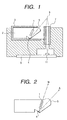
- Fig. 1 is a view showing a contact type image sensor in a first embodiment of the present invention.
- Fig. 2 is a sectional view of the light guide 2.
- the light radiated from the light source 1 constituted of the light emitting elements such as LED disposed on the end surface of the light guide 2 is incident upon the inside of the light guide 2 constituted of a light transmitting member, repeatedly reflected by the inner face of the light guide 2 and thereby guided in the longitudinal direction of the light guide 2.
- a part of the light guide 2 is provided with the diffusing surface 4 for diffusing and/or reflecting the incident light along the longitudinal direction.
- the diffusing surface 4 When the light repeatedly reflected by the inner face in the longitudinal direction is incident upon the diffusing surface 4 as shown in Fig. 2, the incident light is scattered and a part of the light contributes as the illumination light to illuminate the original.
- the light guide cover 3 is disposed outside the light guide 2 to enhance the light utilization efficiency, and attached so as to cover the light guide via the air layer so that the light leaking from the light guide 2 in the direction different from the original irradiation direction is returned into the light guide.
- the light guide cover 3 is formed, for example, of a white light non-transmitting member with high light reflecting properties.
- the original (not shown) positioned on the read line 6 is illuminated with the light radiated from the radiating surface 5 (the surface of the light guide 2 radiating the light which contributes to the lighting of the original as the object to be illuminated) of the light guide 2 in the opening of the light guide cover 3, and the reflected light is formed into an image by the rod lens array 7 on the line sensor 11 disposed on the sensor array 9.
- the line sensor 11 converts the information of the light formed into the image to an electric signal and outputs the signal, the reading of the original is carried out.
- the radiating surface 5 in a lens shape, the surface is constituted so that a more intense light can be converged on the read line 6.
- Fig. 2 is a view showing only the light guide 2 having in its end portion the light emitting elements 1 such as LED constituting the illumination apparatus of the contact type image sensor shown in Fig. 1.
- the light emitting elements 1 such as LED constituting the illumination apparatus of the contact type image sensor shown in Fig. 1.
- the light guide of the present embodiment three light emitting elements 1 are arranged on a normal line N substantially passing through the center of the width of the diffusing surface.
- the number of LEDs as the light emitting elements is not limited to three, and for example, only one may be disposed.
- the normal line passing through the center of the width of the diffusing surface is identical to the illumination direction of the original, the illuminance becomes intense in the end portion in which the light emitting elements 1 are arranged as in the conventional art, and a non-uniform irradiation characteristic is provided in the longitudinal direction. Therefore, in the present embodiment, when viewed from the end surface side of the longitudinal direction of the light guide in the sectional view of Fig. 1 or 2, the normal line N passing through the center of the width of the diffusing surface is allowed to be different from the direction in which the original is illuminated.
- the light is directly incident upon the diffusing surface of the light guide, and the regular reflected light from the diffusing surface does not directly contribute as the illumination light of the object to be illuminated, a uniform illuminance distribution can be obtained in the longitudinal direction. Moreover, since a part of the light other than the regular reflected light is radiated from the radiating surface, and contributes as the illumination light of the object to be illuminated, the vicinity of the light source is prevented from becoming excessively dark. Since a predetermined illuminance can be obtained, the total length of the light guide in the longitudinal direction can be shortened.
- the illumination apparatus of the present embodiment is used in the reading apparatus, reading can be realized so that color can uniformly be reproduced over the longitudinal direction.
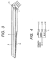
- Fig. 3 shows a perspective view of the light guide 2 in the present embodiment.
- the light guide of the present embodiment is provided with a tapered surface 13 so that the sectional area of the light guide becomes smaller when farther from the end portion with the light emitting elements 1 arranged thereon. Even unless the tapered surface 13 is disposed, a uniform light can be obtained over the longitudinal direction, but by disposing the tapered surface, the original can be irradiated with the light of a further uniform light emitting intensity over the entire area in the longitudinal direction of the light guide 2.
- a second embodiment will be described in which the present invention is applied to the image sensor for reading a color image.
- three color light emitting elements of red (R), green (G) and blue (B) are used, and the original is illuminated by successively switching and lighting each color light source. Subsequently, the light information of three colors R, G, B obtained from the original is formed into an image on the line sensor 11 by the lens array, and the line sensor 11 converts the light information of three colors R, G, B into an electric signal, so that a color image signal can be obtained.
- Fig. 4 shows an equivalent circuit when the LED light source is used as color light emitting elements. As shown in Fig. 4, the LEDs are constituted of independent cathodes and a common anode.
- Figs. 5A, 5B are views showing a case molded type LED light source. Fig. 5A is a top view of the case molded type color LED light source, Fig. 5B is a sectional view thereof, and Fig. 6 is a view showing the connection state of each LED onto a lead frame.
- This case molded type LED light source is manufactured as follows: First, a lead frame 18 is inserted to a metal mold, and injection molding is performed, so that the portion of the lead frame 18 other than the portion with the LED elements mounted thereon is covered with a white resin 20 with high light reflecting properties. Subsequently, the anodes of three color LED elements of R-LED element, G-LED element, B-LED element are connected to a common base pin (2) of the lead frame 18, and cathodes are further connected to color dedicated pins (1), (3), (4) of the lead frame. Subsequently, by potting a light transmitting resin 19 on the three color LED elements, the LED light source is completed.
- the light source can correctly be positioned and fixed.
- the examples in which the LEDs are used as the light emitting elements have been described, but the present invention is not limited to the examples, and other light emitting elements may be used.
- the light sources can closely be mounted, so that the corresponding light guide can be thinned.
- the object to be illuminated can be illuminated with the light which has a uniform illuminance distribution over the longitudinal direction of the light guide.
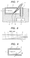
- Fig. 7 is a view showing the contact type image sensor in a third embodiment of the present invention.
- Fig. 8 is a sectional view of the light guide 2.
- the light radiated from the light source 1 constituted of the light emitting elements such as LED disposed on the end surface of the light guide 2 is incident upon the inside of the light guide 2 constituted of the light transmitting member, repeatedly reflected by the inner face of the light guide 2 and thereby guided in the longitudinal direction of the light guide 2.
- a part of the light guide 2 is provided with the diffusing surface 4 along the longitudinal direction.
- the light guide cover 3 as shown in Fig. 22 is disposed outside the light guide 2 to enhance the light utilization efficiency, and attached so as to cover the light guide via the air layer so that the light leaking from the light guide 2 in the direction different from the original illumination direction is returned into the light guide.
- the light guide cover 3 is formed, for example, of a white light non-transmitting member with high light reflecting properties.
- the original (not shown) positioned on the read line 6 is illuminated with the light radiated from the radiating surface 5 (the surface of the light guide 2 radiating the light which contributes to the illumination of the original as the object to be illuminated) of the light guide 2 in the opening of the light guide cover 3, and the reflected light is formed into an image by the rod lens array 7 on the line sensor 11 disposed on the sensor array 9. Subsequently, when the line sensor 11 converts the information of the light formed into the image to an electric signal and outputs the signal, the reading of the original is carried out.
- the radiating surface 5 in a lens shape, the surface is constituted so that a more intense light can be converged on the read line 6.
- Fig. 9 is a view showing only the light guide 2 having in its end portion the light emitting elements 1 such as LED constituting the illumination apparatus of the contact type image sensor shown in Fig. 7 and the light guide cover 3.
- a total reflection surface 10 is disposed as a light leakage preventing portion for restricting light leakage in the portion other than the radiating surface 5 in the portion of the light guide 2 exposed to the outside in the opening of the light guide cover 3.
- Fig. 10 is an enlarged view in the vicinity of the diffusing surface 4 and the total reflection surface 10.
- the total reflection surface will be described which utilizes a difference of refractive index in an interface of the light guide and air.
- the light radiated from the light emitting element 1 is repeatedly reflected by the inner face of the light guide 2 and guided in the longitudinal direction, and among the light, the light incident upon the diffusing surface 4 illuminates the original from the radiating surface 5.
- the total reflection surface 10 is thus constituted of the portion other than the radiating surface 5 in the exposed portion positioned in the opening of the light guide cover 3 of the light guide 2, the conventional light leakage can be prevented. Subsequently, the light reflected by the diffusing surface 4 to reach the total reflection surface 10 is totally reflected toward the inside of the light guide 2, a part of the light is radiated from the radiating surface 5, and the light not-radiated from the radiating surface 5 is also diffused and/or reflected again by the diffusing surface 4 to act as the light for illuminating the original when reaching the radiating surface 5, so that the original can be illuminated with a sufficient illuminance.
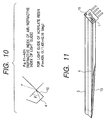
- Fig. 11 shows a perspective view of the light guide 2 in the present embodiment.
- the tapered surface 13 is disposed so that the sectional area of the light guide becomes smaller when it is farther from the end portion with the light emitting elements 1 arranged thereon..By disposing the tapered surface 13, the light emitting intensity only of the side on which the light emitting elements 1 are arranged is prevented from being strengthened, and the original can be illuminated with the light of a uniform light emitting intensity over the entire area in the longitudinal direction of the light guide 2.
- Fig. 12 is a view showing a fourth embodiment in which the total reflection surface 10 is formed as an ellipse with a point P1 as the center position of the diffusing surface 4 and a center P2 as the irradiation position (i.e., the read line by the line sensor) of the original as the object to be illuminated by the light source.
- the diffusing surface 4 is formed by applying a white light diffusing ink or the like to the surface of the light guide 2 as shown in Figs. 13A to 13D.
- Fig. 13A shows an example in which both the radiating surface 5 and the total reflection surface 10 are formed of flat surfaces
- Fig. 13B shows an example in which the radiating surface 5 is constituted of the flat surface and the total reflection surface 10 is formed as the elliptic surface.
- the radiating surface 5 is formed in a lens shape
- the total reflection surface 10 is formed of the flat surface and the tapered surface in a direction apart from the light emitting element 1
- the terminal line of the light guide 2 is shown by a dot line 21.
- Fig. 13D shows an example in which the reflecting surface is constituted by constituting the radiating surface 5 of the flat surface and disposing a reflecting member 22 separately from the light guide cover 3.
- the reflective surface may be formed, for example, by roughing the surface of the light guide, applying a white paint with light diffusing/reflecting properties, or by depositing a metal or applying a metal gloss paint to a portion processed in a sawtooth shape.
- the width of the diffusing surface 4 can be formed to be constant without being changed, so that compared with the case in which the radiating surface 5 is lens-shaped, the light can effectively be converged.
- Fig. 16 shows a facsimile machine having a transmitting/receiving function as an information processing apparatus which uses the contact type image sensor of the above-described embodiment.
- numeral 100 denotes the contact type image sensor described in the above-described embodiments
- 102 denotes a sheet supply roller for supplying an original 17 as the illuminated object toward a reading position
- 104 denotes a separating piece for securely separating the original sheet by sheet
- 18 denotes a conveying roller disposed in the reading position of the contact type image sensor 100 for regulating the surface to be read of the original and conveying the original.
- character W denotes a recording medium having a roll sheet shape.
- a thermal head, an ink jet recording head, and the like can be used for a recording head 110 for forming images.
- a platen roller 112 conveys the recording medium W to a recording position by the recording head 110, and regulates the surface to be recorded.
- An operation panel 120 is provided with a switch for accepting operation inputs, a display section for detecting messages or the states of other apparatuses, and the like.
- a system control substrate 130 is provided with a controller for controlling each section, a drive circuit for performing the lighting control of the light source of the contact type image sensor 100 and the drive control of sensors, an image information processor, a transmitter/receiver, and the like.
- Numeral 140 denotes an apparatus power source.
- the original is supplied to the reading position of the image sensor 100 by the supply roller 102. Subsequently, the image information on the original 17 is read by the image sensor 100 driven/controlled by the drive circuit, and converted to an electric signal. The converted electric signal is subjected to a predetermined image processing in the processor of the system control substrate 130, and outputted to a public circuit via the transmitter/receiver.
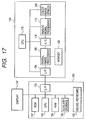
- the facsimile machine having the transmitting/receiving function has been described as the example of the information processing apparatus, but a seventh embodiment will be described with reference to Fig. 17 as one example of the information processing apparatus constituted by using the contact type image sensor described in the above-described embodiments.
- an image reading apparatus 150 with a contact type image sensor 200 built therein is connected to a personal computer 160 and systematized, and a read image is transmitted to the computer or a network.
- a CPU 170 controls the entire image reading apparatus 150 as first control means
- the contact type color image sensor 200 is constituted as a reading unit of the above-described light source, CCD line sensor, and the like to convert the image of the original as the illuminated object to an image signal
- an analog signal processing circuit 116 applies a gain adjustment or another analog processing to the analog image signal outputted from the contact type color image sensor 200.
- numeral 118 denotes an A/D converter for converting the output of the analog signal processing circuit 116 to a digital signal
- 180 denotes an image processing circuit for using a memory 122 to apply a shading correction processing, a gamma conversion processing, a magnification change processing, or another image processing to the output data of the A/D converter 118
- 124 denotes an interface for outputting to the outside the digital image data processed by the image processing circuit 180.
- the interface 124 conforms to the specification employed, for example, in personal computers such as SCSI and Bi-Centronics in a standard manner, and is connected to the personal computer 160.
- These analog signal processing circuit 116, A/D converter 118, image processing circuit 180, and memory 122 constitute the signal processing means.
- the personal computer 160 as second control means is provided with an optomagnetic disk drive, a floppy disk drive, and the like as an external storage apparatus or an auxiliary storage apparatus 132.
- Numeral 134 denotes a display for displaying the operation on the personal computer 160, and 133 denotes a mouse/keyboard for inputting a command, and the like to the personal computer.
- 135 denotes an interface for transmitting/receiving the data, command, and image reading apparatus state information between the personal computer and the image reading apparatus.
- a CPU 136 of the personal computer 160 can input a reading instruction to the CPU 170 of the image reading apparatus via the mouse/keyboard 133.
- the CPU 136 transmits a reading command to the CPU 170 of the image reading apparatus via the interface 135.
- the CPU 136 of the personal computer 160 controls the CPU 170 of the image reading apparatus in accordance with the control program information stored in a ROM 137, and the CPU 170 performs the drive control of the light source and CCD and the control of the signal processing means.
- the control program may be executed by the CPU 136 by reading the program stored in the storage media such as the optomagnetic disk and floppy disk attached to the auxiliary storage apparatus 132 into the personal computer 160.
- the reading speed can be increased, and high resolution and high performance can be realized.
- the light utilization efficiency can be enhanced when the light guide is used in the illumination apparatus, and the illuminance of irradiating the lighting object can be increased.
- the number of light sources such as LED can be decreased, which can realize cost reduction.
Applications Claiming Priority (3)
| Application Number | Priority Date | Filing Date | Title |
|---|---|---|---|
| JP10366932A JP3083092B2 (ja) | 1998-12-24 | 1998-12-24 | 照明装置及び密着型イメージセンサ及び画像読取システム |
| JP36692698A JP3176346B2 (ja) | 1998-12-24 | 1998-12-24 | 導光体及び照明装置及び密着型イメージセンサ及び画像読取システム |
| EP99310365A EP1017222A3 (de) | 1998-12-24 | 1999-12-21 | Beleuchtungs-Gerät mit Benutzung von Lichtleitern |
Related Parent Applications (1)
| Application Number | Title | Priority Date | Filing Date |
|---|---|---|---|
| EP99310365A Division EP1017222A3 (de) | 1998-12-24 | 1999-12-21 | Beleuchtungs-Gerät mit Benutzung von Lichtleitern |
Publications (1)
| Publication Number | Publication Date |
|---|---|
| EP1624667A2 true EP1624667A2 (de) | 2006-02-08 |
Family
ID=26581847
Family Applications (2)
| Application Number | Title | Priority Date | Filing Date |
|---|---|---|---|
| EP99310365A Withdrawn EP1017222A3 (de) | 1998-12-24 | 1999-12-21 | Beleuchtungs-Gerät mit Benutzung von Lichtleitern |
| EP05077439A Withdrawn EP1624667A2 (de) | 1998-12-24 | 1999-12-21 | Beleuchtungs-Gerät mit Benutzung von Lichtleitern |
Family Applications Before (1)
| Application Number | Title | Priority Date | Filing Date |
|---|---|---|---|
| EP99310365A Withdrawn EP1017222A3 (de) | 1998-12-24 | 1999-12-21 | Beleuchtungs-Gerät mit Benutzung von Lichtleitern |
Country Status (3)
| Country | Link |
|---|---|
| US (3) | US6333779B1 (de) |
| EP (2) | EP1017222A3 (de) |
| TW (1) | TW479430B (de) |
Cited By (1)
| Publication number | Priority date | Publication date | Assignee | Title |
|---|---|---|---|---|
| WO2011015006A1 (zh) * | 2009-08-07 | 2011-02-10 | 威海华菱光电有限公司 | 一种接触式图像传感器 |
Families Citing this family (35)
| Publication number | Priority date | Publication date | Assignee | Title |
|---|---|---|---|---|
| US6714323B1 (en) * | 1999-06-02 | 2004-03-30 | Rohm Co., Ltd. | Image reading apparatus and light conductor used for the same |
| JP3912945B2 (ja) * | 1999-11-19 | 2007-05-09 | 日本板硝子株式会社 | 棒状導光体およびそれを組込んだ照明装置、原稿読取装置 |
| TW503646B (en) * | 2000-03-16 | 2002-09-21 | Nippon Sheet Glass Co Ltd | Line illuminating device |
| US6744033B2 (en) * | 2000-08-01 | 2004-06-01 | Nippon Sheet Glass Co., Ltd. | Bar-shaped light guide, line-illuminating device incorporated with the bar-shaped light guide and contact-type image sensor incorporated with the line-illuminating device |
| TW527817B (en) * | 2000-08-11 | 2003-04-11 | Canon Kk | Image sensor and image reading apparatus |
| US7173677B2 (en) * | 2001-04-12 | 2007-02-06 | Rohm Co., Ltd. | Back light unit for liquid crystal display device and method for manufacturing the unit |
| DE10158395B4 (de) * | 2001-11-28 | 2011-07-07 | OSRAM Opto Semiconductors GmbH, 93055 | LED-Beleuchtungssystem |
| US6837605B2 (en) * | 2001-11-28 | 2005-01-04 | Osram Opto Semiconductors Gmbh | Led illumination system |
| KR100622404B1 (ko) * | 2002-10-23 | 2006-09-13 | 주식회사 애트랩 | 광 이미지 검출기 및 이를 채택하는 광 마우스 |
| EP1511289B1 (de) * | 2003-08-19 | 2011-11-23 | Ricoh Company, Ltd. | Beleuchtungsanordnung, Bildlesevorrichtung und Bilderzeugungsgerät |
| US7605951B2 (en) * | 2004-02-10 | 2009-10-20 | Ricoh Company, Ltd. | Image reader, image forming and reproducing apparatus, and image reading method |
| JP2005269108A (ja) * | 2004-03-17 | 2005-09-29 | Nippon Sheet Glass Co Ltd | ライン照明装置およびライン照明装置を組み込んだ画像読取装置 |
| JP4168960B2 (ja) * | 2004-03-24 | 2008-10-22 | 富士ゼロックス株式会社 | 画像読み取り装置、画像読み取りユニット、光照射装置 |
| US20070297189A1 (en) * | 2004-06-02 | 2007-12-27 | Wu Rong Y | Linear light source for enhancing uniformity of beaming light within the beaming light's effective focal range |
| US7746520B2 (en) * | 2004-11-23 | 2010-06-29 | Xerox Corporation | Document illuminator |
| US20060152777A1 (en) * | 2004-12-06 | 2006-07-13 | Takeshi Iwasaki | Image processing method and apparatus capable of effectively reading an image using a light diffuser |
| US7333208B2 (en) * | 2004-12-20 | 2008-02-19 | Xerox Corporation | Full width array mechanically tunable spectrophotometer |
| US7715063B2 (en) * | 2005-03-31 | 2010-05-11 | Xerox Corporation | CVT integrated illuminator |
| US7593143B2 (en) * | 2005-03-31 | 2009-09-22 | Xerox Corporation | Compound curved concentrator based illuminator |
| US7755811B2 (en) * | 2005-06-30 | 2010-07-13 | Xerox Corporation | Document illuminator |
| US7852530B2 (en) * | 2005-10-31 | 2010-12-14 | Hewlett-Packard Development Company, L.P. | Illumination source comprising a plurality of light emitting diode groups |
| US7835038B2 (en) * | 2005-10-31 | 2010-11-16 | Hewlett-Packard Development Company, L.P. | Illumination source comprising more light emitting diodes than terminals |
| WO2007105293A1 (ja) * | 2006-03-13 | 2007-09-20 | Canon Components, Inc. | ライン状照明装置及びそれを用いた画像読取装置 |
| US7864381B2 (en) * | 2007-03-20 | 2011-01-04 | Xerox Corporation | Document illuminator with LED-driven phosphor |
| JP2008270305A (ja) * | 2007-04-17 | 2008-11-06 | Nichia Corp | 発光装置 |
| JP2009081644A (ja) * | 2007-09-26 | 2009-04-16 | Rohm Co Ltd | 導光体、およびイメージセンサモジュール |
| US8674212B2 (en) * | 2008-01-15 | 2014-03-18 | General Electric Company | Solar cell and magnetically self-assembled solar cell assembly |
| JP2009246462A (ja) * | 2008-03-28 | 2009-10-22 | Kyocera Mita Corp | 画像読取装置及び画像形成装置 |
| JP5288880B2 (ja) * | 2008-05-21 | 2013-09-11 | 京セラドキュメントソリューションズ株式会社 | 画像読取装置及び画像形成装置 |
| JP4757340B2 (ja) * | 2009-10-30 | 2011-08-24 | シャープ株式会社 | 照明装置、その照明装置を備える画像読取り装置、その画像読取り装置を備える画像形成装置 |
| IT1396799B1 (it) * | 2009-12-17 | 2012-12-14 | Cts Cashpro Spa | Sensore di immagine a contatto e metodo per migliorare la risposta di un sensore di immagine a contatto, in particolare per la scansione di banconote |
| FR2963527B1 (fr) * | 2010-07-30 | 2013-05-24 | Sagemcom Documents Sas | Scanner recto verso d'un document, et procede de commande associe |
| JP5935487B2 (ja) | 2012-04-25 | 2016-06-15 | 三菱電機株式会社 | 照明装置、イメージセンサ及びそれらの製造方法 |
| US9338322B2 (en) * | 2013-06-11 | 2016-05-10 | Canon Kabushiki Kaisha | Image reading device and image forming apparatus including an illuminating unit and an aligning portion for positioning an original |
| JP6408259B2 (ja) * | 2014-06-09 | 2018-10-17 | 株式会社キーエンス | 画像検査装置、画像検査方法、画像検査プログラム及びコンピュータで読み取り可能な記録媒体並びに記録した機器 |
Family Cites Families (23)
| Publication number | Priority date | Publication date | Assignee | Title |
|---|---|---|---|---|
| US4287414A (en) * | 1979-06-29 | 1981-09-01 | International Business Machines Corp. | Illumination and pick up apparatus |
| DE3524811A1 (de) | 1984-07-14 | 1986-01-23 | Canon K.K., Tokio/Tokyo | Bildabtastvorrichtung |
| US4680644A (en) | 1984-07-23 | 1987-07-14 | Canon Kabushiki Kaisha | Method and apparatus for reading an image |
| JPS6139771A (ja) | 1984-07-31 | 1986-02-25 | Canon Inc | 画像読取装置 |
| JPS62172859A (ja) | 1986-01-27 | 1987-07-29 | Canon Inc | 画像読取り装置 |
| US4996606A (en) | 1987-11-14 | 1991-02-26 | Canon Kabushiki Kaisha | Light emitting device and original reading apparatus having the device |
| US5233442A (en) | 1989-06-07 | 1993-08-03 | Canon Kabushiki Kaisha | Photosensor and image reading device with improved correction means for signal correction and image reading method |
| JP2929550B2 (ja) | 1989-06-07 | 1999-08-03 | キヤノン株式会社 | 光センサ及び画像読取装置 |
| US5101285A (en) | 1989-07-24 | 1992-03-31 | Canon Kabushiki Kaisha | Photoelectric conversion device having an improved illuminating system and information processing apparatus mounting the device |
| JP2744307B2 (ja) | 1989-11-21 | 1998-04-28 | キヤノン株式会社 | 光電変換装置 |
| JP2974461B2 (ja) | 1991-07-25 | 1999-11-10 | キヤノン株式会社 | 原稿画像読取装置 |
| DE69325337T2 (de) * | 1992-11-04 | 1999-11-18 | Canon Kk | Kontaktbildsensor und Abtastverfahren mittels eines solchen Sensors |
| KR0158247B1 (ko) * | 1993-01-19 | 1999-03-20 | 미따라이 하지메 | 도광체와, 이 도광체를 갖는 조명 장치, 그리고 이 조명 장치를 갖는 화상 판독장치 및 정보 처리 장치 |
| JPH08125814A (ja) | 1994-10-28 | 1996-05-17 | Canon Inc | 光電変換装置及び情報処理装置 |
| US5880852A (en) | 1995-05-23 | 1999-03-09 | Canon Kabushiki Kaisha | Reading unit and recording apparatus on which the reading unit is mountable |
| DE69626567T2 (de) | 1995-05-26 | 2003-11-27 | Canon Kk | Leseeinheit und Aufzeichnungsgerät auf das eine solche Leseeinheit gesetzt werden kann |
| JP3459714B2 (ja) | 1996-01-05 | 2003-10-27 | キヤノン株式会社 | 画像読取装置 |
| JP3754738B2 (ja) * | 1996-01-17 | 2006-03-15 | キヤノン株式会社 | 画像読取装置 |
| JP3176303B2 (ja) | 1996-02-09 | 2001-06-18 | キヤノン株式会社 | 信号処理装置 |
| JP3181853B2 (ja) * | 1997-04-10 | 2001-07-03 | キヤノン株式会社 | 密着型イメージセンサ及び情報処理装置 |
| JP3167111B2 (ja) * | 1997-04-25 | 2001-05-21 | キヤノン株式会社 | 画像読取装置 |
| DE19804232C2 (de) * | 1998-02-04 | 2000-06-29 | Daimler Chrysler Ag | Brennkammer für Hochleistungstriebwerke und Düsen |
| US6129675A (en) * | 1998-09-11 | 2000-10-10 | Jay; Gregory D. | Device and method for measuring pulsus paradoxus |
-
1999
- 1999-12-21 EP EP99310365A patent/EP1017222A3/de not_active Withdrawn
- 1999-12-21 EP EP05077439A patent/EP1624667A2/de not_active Withdrawn
- 1999-12-21 US US09/467,982 patent/US6333779B1/en not_active Expired - Lifetime
- 1999-12-22 TW TW088122668A patent/TW479430B/zh not_active IP Right Cessation
-
2001
- 2001-11-01 US US09/985,115 patent/US6661497B2/en not_active Expired - Lifetime
- 2001-11-01 US US09/985,045 patent/US6473154B2/en not_active Expired - Lifetime
Cited By (1)
| Publication number | Priority date | Publication date | Assignee | Title |
|---|---|---|---|---|
| WO2011015006A1 (zh) * | 2009-08-07 | 2011-02-10 | 威海华菱光电有限公司 | 一种接触式图像传感器 |
Also Published As
| Publication number | Publication date |
|---|---|
| TW479430B (en) | 2002-03-11 |
| US6473154B2 (en) | 2002-10-29 |
| US6661497B2 (en) | 2003-12-09 |
| US20020030803A1 (en) | 2002-03-14 |
| EP1017222A3 (de) | 2004-05-06 |
| US6333779B1 (en) | 2001-12-25 |
| EP1017222A2 (de) | 2000-07-05 |
| US20020030798A1 (en) | 2002-03-14 |
Similar Documents
| Publication | Publication Date | Title |
|---|---|---|
| US6473154B2 (en) | Illumination apparatus using light guide | |
| US7050657B2 (en) | Image reading system | |
| US6239421B1 (en) | Rod lens array and image read apparatus and system using the same | |
| US6375335B1 (en) | Illumination device and information processing apparatus | |
| US20020015193A1 (en) | Illumination device, image sensor having the illumination device, image reading apparatus and information processing system using the image sensor | |
| JPH1093765A (ja) | 導光体及び照明装置及び画像読取装置及び画像読取システム | |
| US6320681B1 (en) | Image reading apparatus | |
| KR100499616B1 (ko) | 조명장치 및 화상판독장치 | |
| US5965870A (en) | Image reading system with means for converging light from a plurality of light sources on a substantially same position to uniformly irradiate an object | |
| EP0822706A2 (de) | Bildlesevorrichtung und -verfahren | |
| JP2002185708A (ja) | 照明装置、イメージセンサユニットおよびこれを備えた画像読み取り装置 | |
| CN1149826C (zh) | 图象读取装置和图象读取系统 | |
| JP3083092B2 (ja) | 照明装置及び密着型イメージセンサ及び画像読取システム | |
| US20020149798A1 (en) | Image scanning system and method for scanner | |
| JP3176346B2 (ja) | 導光体及び照明装置及び密着型イメージセンサ及び画像読取システム | |
| JP3612892B2 (ja) | 透過原稿ユニット及びこれを用いた画像読み取り装置 | |
| JP2004221729A (ja) | 密着型イメージセンサ及びそれを用いた密着型画像読み取り装置 | |
| CN102238310A (zh) | 图像读取装置 | |
| JP2000092289A (ja) | 画像読取装置及び画像読取方法 | |
| JPH1098592A (ja) | 画像読取り装置及び情報処理装置及び光学装置及び光学システム | |
| JPH11331505A (ja) | 透過原稿用照明装置、原稿読取装置、及び情報処理装置 | |
| JP2004040821A (ja) | 画像読取り装置及び情報処理装置及び光学装置及び光学システム | |
| JP2004015827A (ja) | 画像読取装置及び画像読取システム |
Legal Events
| Date | Code | Title | Description |
|---|---|---|---|
| PUAI | Public reference made under article 153(3) epc to a published international application that has entered the european phase |
Free format text: ORIGINAL CODE: 0009012 |
|
| AC | Divisional application: reference to earlier application |
Ref document number: 1017222 Country of ref document: EP Kind code of ref document: P |
|
| AK | Designated contracting states |
Kind code of ref document: A2 Designated state(s): DE FR GB |
|
| STAA | Information on the status of an ep patent application or granted ep patent |
Free format text: STATUS: THE APPLICATION HAS BEEN WITHDRAWN |
|
| 18W | Application withdrawn |
Effective date: 20060622 |