EP1624347B1 - Elément de chargement, cartouche de traitement et appareil électrophotographique - Google Patents
Elément de chargement, cartouche de traitement et appareil électrophotographique Download PDFInfo
- Publication number
- EP1624347B1 EP1624347B1 EP05017566.0A EP05017566A EP1624347B1 EP 1624347 B1 EP1624347 B1 EP 1624347B1 EP 05017566 A EP05017566 A EP 05017566A EP 1624347 B1 EP1624347 B1 EP 1624347B1
- Authority
- EP
- European Patent Office
- Prior art keywords
- charging member
- metal oxide
- particles
- oxide particles
- charging
- Prior art date
- Legal status (The legal status is an assumption and is not a legal conclusion. Google has not performed a legal analysis and makes no representation as to the accuracy of the status listed.)
- Ceased
Links
- 238000000034 method Methods 0.000 title claims description 33
- 230000008569 process Effects 0.000 title claims description 16
- 239000002245 particle Substances 0.000 claims description 220
- 229910044991 metal oxide Inorganic materials 0.000 claims description 127
- 150000004706 metal oxides Chemical class 0.000 claims description 127
- GWEVSGVZZGPLCZ-UHFFFAOYSA-N Titan oxide Chemical compound O=[Ti]=O GWEVSGVZZGPLCZ-UHFFFAOYSA-N 0.000 claims description 66
- 239000011246 composite particle Substances 0.000 claims description 56
- VYPSYNLAJGMNEJ-UHFFFAOYSA-N Silicium dioxide Chemical compound O=[Si]=O VYPSYNLAJGMNEJ-UHFFFAOYSA-N 0.000 claims description 51
- 239000006229 carbon black Substances 0.000 claims description 51
- OGIDPMRJRNCKJF-UHFFFAOYSA-N titanium oxide Inorganic materials [Ti]=O OGIDPMRJRNCKJF-UHFFFAOYSA-N 0.000 claims description 34
- 238000012546 transfer Methods 0.000 claims description 33
- 239000000377 silicon dioxide Substances 0.000 claims description 23
- 238000004381 surface treatment Methods 0.000 claims description 18
- 229920005558 epichlorohydrin rubber Polymers 0.000 claims description 14
- UQSXHKLRYXJYBZ-UHFFFAOYSA-N Iron oxide Chemical compound [Fe]=O UQSXHKLRYXJYBZ-UHFFFAOYSA-N 0.000 claims description 13
- 239000011230 binding agent Substances 0.000 claims description 12
- IAYPIBMASNFSPL-UHFFFAOYSA-N Ethylene oxide Chemical group C1CO1 IAYPIBMASNFSPL-UHFFFAOYSA-N 0.000 claims description 11
- AOWKSNWVBZGMTJ-UHFFFAOYSA-N calcium titanate Chemical compound [Ca+2].[O-][Ti]([O-])=O AOWKSNWVBZGMTJ-UHFFFAOYSA-N 0.000 claims description 7
- VEALVRVVWBQVSL-UHFFFAOYSA-N strontium titanate Chemical compound [Sr+2].[O-][Ti]([O-])=O VEALVRVVWBQVSL-UHFFFAOYSA-N 0.000 claims description 7
- 150000003961 organosilicon compounds Chemical class 0.000 claims description 6
- PNEYBMLMFCGWSK-UHFFFAOYSA-N aluminium oxide Inorganic materials [O-2].[O-2].[O-2].[Al+3].[Al+3] PNEYBMLMFCGWSK-UHFFFAOYSA-N 0.000 claims description 5
- 239000000395 magnesium oxide Substances 0.000 claims description 5
- CPLXHLVBOLITMK-UHFFFAOYSA-N magnesium oxide Inorganic materials [Mg]=O CPLXHLVBOLITMK-UHFFFAOYSA-N 0.000 claims description 5
- AXZKOIWUVFPNLO-UHFFFAOYSA-N magnesium;oxygen(2-) Chemical compound [O-2].[Mg+2] AXZKOIWUVFPNLO-UHFFFAOYSA-N 0.000 claims description 5
- JRPBQTZRNDNNOP-UHFFFAOYSA-N barium titanate Chemical compound [Ba+2].[Ba+2].[O-][Ti]([O-])([O-])[O-] JRPBQTZRNDNNOP-UHFFFAOYSA-N 0.000 claims description 4
- 229910002113 barium titanate Inorganic materials 0.000 claims description 4
- 239000010410 layer Substances 0.000 description 197
- 238000005259 measurement Methods 0.000 description 43
- 239000000463 material Substances 0.000 description 39
- 239000003795 chemical substances by application Substances 0.000 description 34
- 229920001971 elastomer Polymers 0.000 description 28
- XYJRNCYWTVGEEG-UHFFFAOYSA-N trimethoxy(2-methylpropyl)silane Chemical compound CO[Si](OC)(OC)CC(C)C XYJRNCYWTVGEEG-UHFFFAOYSA-N 0.000 description 28
- OKTJSMMVPCPJKN-UHFFFAOYSA-N Carbon Chemical compound [C] OKTJSMMVPCPJKN-UHFFFAOYSA-N 0.000 description 26
- 229920002725 thermoplastic elastomer Polymers 0.000 description 24
- 239000005060 rubber Substances 0.000 description 22
- -1 polysiloxanes Polymers 0.000 description 21
- 229920005989 resin Polymers 0.000 description 17
- 239000011347 resin Substances 0.000 description 17
- RTAQQCXQSZGOHL-UHFFFAOYSA-N Titanium Chemical compound [Ti] RTAQQCXQSZGOHL-UHFFFAOYSA-N 0.000 description 15
- 230000000694 effects Effects 0.000 description 15
- 238000000576 coating method Methods 0.000 description 14
- 238000011156 evaluation Methods 0.000 description 14
- 239000011248 coating agent Substances 0.000 description 13
- 239000012530 fluid Substances 0.000 description 12
- 229920001296 polysiloxane Polymers 0.000 description 11
- 229910052782 aluminium Inorganic materials 0.000 description 10
- XAGFODPZIPBFFR-UHFFFAOYSA-N aluminium Chemical compound [Al] XAGFODPZIPBFFR-UHFFFAOYSA-N 0.000 description 10
- 150000001875 compounds Chemical class 0.000 description 10
- 229920001577 copolymer Polymers 0.000 description 10
- 239000002002 slurry Substances 0.000 description 10
- 239000000243 solution Substances 0.000 description 10
- YXFVVABEGXRONW-UHFFFAOYSA-N Toluene Chemical compound CC1=CC=CC=C1 YXFVVABEGXRONW-UHFFFAOYSA-N 0.000 description 9
- XLOMVQKBTHCTTD-UHFFFAOYSA-N Zinc monoxide Chemical compound [Zn]=O XLOMVQKBTHCTTD-UHFFFAOYSA-N 0.000 description 8
- 238000003825 pressing Methods 0.000 description 8
- 239000002904 solvent Substances 0.000 description 8
- 230000000052 comparative effect Effects 0.000 description 7
- 239000007822 coupling agent Substances 0.000 description 7
- 239000006185 dispersion Substances 0.000 description 7
- 229910052751 metal Inorganic materials 0.000 description 7
- 239000002184 metal Substances 0.000 description 7
- 238000002156 mixing Methods 0.000 description 7
- 239000000203 mixture Substances 0.000 description 7
- 239000007787 solid Substances 0.000 description 7
- STMDPCBYJCIZOD-UHFFFAOYSA-N 2-(2,4-dinitroanilino)-4-methylpentanoic acid Chemical compound CC(C)CC(C(O)=O)NC1=CC=C([N+]([O-])=O)C=C1[N+]([O-])=O STMDPCBYJCIZOD-UHFFFAOYSA-N 0.000 description 6
- BRLQWZUYTZBJKN-UHFFFAOYSA-N Epichlorohydrin Chemical compound ClCC1CO1 BRLQWZUYTZBJKN-UHFFFAOYSA-N 0.000 description 6
- YCKRFDGAMUMZLT-UHFFFAOYSA-N Fluorine atom Chemical compound [F] YCKRFDGAMUMZLT-UHFFFAOYSA-N 0.000 description 6
- XEEYBQQBJWHFJM-UHFFFAOYSA-N Iron Chemical compound [Fe] XEEYBQQBJWHFJM-UHFFFAOYSA-N 0.000 description 6
- 238000004140 cleaning Methods 0.000 description 6
- 235000014113 dietary fatty acids Nutrition 0.000 description 6
- 238000001035 drying Methods 0.000 description 6
- 239000000806 elastomer Substances 0.000 description 6
- 239000000194 fatty acid Substances 0.000 description 6
- 229930195729 fatty acid Natural products 0.000 description 6
- 150000004665 fatty acids Chemical class 0.000 description 6
- 239000011737 fluorine Substances 0.000 description 6
- 229910052731 fluorine Inorganic materials 0.000 description 6
- 235000013980 iron oxide Nutrition 0.000 description 6
- 229920000642 polymer Polymers 0.000 description 6
- 239000000126 substance Substances 0.000 description 6
- CPUDPFPXCZDNGI-UHFFFAOYSA-N triethoxy(methyl)silane Chemical compound CCO[Si](C)(OCC)OCC CPUDPFPXCZDNGI-UHFFFAOYSA-N 0.000 description 6
- 239000005057 Hexamethylene diisocyanate Substances 0.000 description 5
- QCWXUUIWCKQGHC-UHFFFAOYSA-N Zirconium Chemical compound [Zr] QCWXUUIWCKQGHC-UHFFFAOYSA-N 0.000 description 5
- 239000000654 additive Substances 0.000 description 5
- 239000011521 glass Substances 0.000 description 5
- RRAMGCGOFNQTLD-UHFFFAOYSA-N hexamethylene diisocyanate Chemical compound O=C=NCCCCCCN=C=O RRAMGCGOFNQTLD-UHFFFAOYSA-N 0.000 description 5
- 238000004898 kneading Methods 0.000 description 5
- 230000002787 reinforcement Effects 0.000 description 5
- 150000003839 salts Chemical class 0.000 description 5
- 239000002344 surface layer Substances 0.000 description 5
- 229910052726 zirconium Inorganic materials 0.000 description 5
- BWLBGMIXKSTLSX-UHFFFAOYSA-N 2-hydroxyisobutyric acid Chemical compound CC(C)(O)C(O)=O BWLBGMIXKSTLSX-UHFFFAOYSA-N 0.000 description 4
- VTYYLEPIZMXCLO-UHFFFAOYSA-L Calcium carbonate Chemical compound [Ca+2].[O-]C([O-])=O VTYYLEPIZMXCLO-UHFFFAOYSA-L 0.000 description 4
- PXHVJJICTQNCMI-UHFFFAOYSA-N Nickel Chemical compound [Ni] PXHVJJICTQNCMI-UHFFFAOYSA-N 0.000 description 4
- WDJHALXBUFZDSR-UHFFFAOYSA-M acetoacetate Chemical compound CC(=O)CC([O-])=O WDJHALXBUFZDSR-UHFFFAOYSA-M 0.000 description 4
- 239000000853 adhesive Substances 0.000 description 4
- 230000001070 adhesive effect Effects 0.000 description 4
- 238000013019 agitation Methods 0.000 description 4
- TZCXTZWJZNENPQ-UHFFFAOYSA-L barium sulfate Chemical compound [Ba+2].[O-]S([O-])(=O)=O TZCXTZWJZNENPQ-UHFFFAOYSA-L 0.000 description 4
- 239000002585 base Substances 0.000 description 4
- 239000011324 bead Substances 0.000 description 4
- 229920005549 butyl rubber Polymers 0.000 description 4
- 230000007547 defect Effects 0.000 description 4
- JJQZDUKDJDQPMQ-UHFFFAOYSA-N dimethoxy(dimethyl)silane Chemical compound CO[Si](C)(C)OC JJQZDUKDJDQPMQ-UHFFFAOYSA-N 0.000 description 4
- NIMLQBUJDJZYEJ-UHFFFAOYSA-N isophorone diisocyanate Chemical compound CC1(C)CC(N=C=O)CC(C)(CN=C=O)C1 NIMLQBUJDJZYEJ-UHFFFAOYSA-N 0.000 description 4
- 229920003049 isoprene rubber Polymers 0.000 description 4
- 239000007788 liquid Substances 0.000 description 4
- 238000004519 manufacturing process Methods 0.000 description 4
- 239000003921 oil Substances 0.000 description 4
- 230000002093 peripheral effect Effects 0.000 description 4
- 229920001084 poly(chloroprene) Polymers 0.000 description 4
- 229920003048 styrene butadiene rubber Polymers 0.000 description 4
- 229920003051 synthetic elastomer Polymers 0.000 description 4
- 239000005061 synthetic rubber Substances 0.000 description 4
- XLYOFNOQVPJJNP-UHFFFAOYSA-N water Substances O XLYOFNOQVPJJNP-UHFFFAOYSA-N 0.000 description 4
- 239000011787 zinc oxide Substances 0.000 description 4
- 229910000859 α-Fe Inorganic materials 0.000 description 4
- YHMYGUUIMTVXNW-UHFFFAOYSA-N 1,3-dihydrobenzimidazole-2-thione Chemical compound C1=CC=C2NC(S)=NC2=C1 YHMYGUUIMTVXNW-UHFFFAOYSA-N 0.000 description 3
- ZWEHNKRNPOVVGH-UHFFFAOYSA-N 2-Butanone Chemical compound CCC(C)=O ZWEHNKRNPOVVGH-UHFFFAOYSA-N 0.000 description 3
- QTBSBXVTEAMEQO-UHFFFAOYSA-N Acetic acid Chemical compound CC(O)=O QTBSBXVTEAMEQO-UHFFFAOYSA-N 0.000 description 3
- CSCPPACGZOOCGX-UHFFFAOYSA-N Acetone Chemical compound CC(C)=O CSCPPACGZOOCGX-UHFFFAOYSA-N 0.000 description 3
- 239000004925 Acrylic resin Substances 0.000 description 3
- 229920000178 Acrylic resin Polymers 0.000 description 3
- UHOVQNZJYSORNB-UHFFFAOYSA-N Benzene Chemical compound C1=CC=CC=C1 UHOVQNZJYSORNB-UHFFFAOYSA-N 0.000 description 3
- RYGMFSIKBFXOCR-UHFFFAOYSA-N Copper Chemical compound [Cu] RYGMFSIKBFXOCR-UHFFFAOYSA-N 0.000 description 3
- LFQSCWFLJHTTHZ-UHFFFAOYSA-N Ethanol Chemical compound CCO LFQSCWFLJHTTHZ-UHFFFAOYSA-N 0.000 description 3
- XEKOWRVHYACXOJ-UHFFFAOYSA-N Ethyl acetate Chemical compound CCOC(C)=O XEKOWRVHYACXOJ-UHFFFAOYSA-N 0.000 description 3
- 239000005977 Ethylene Substances 0.000 description 3
- 239000005058 Isophorone diisocyanate Substances 0.000 description 3
- FYYHWMGAXLPEAU-UHFFFAOYSA-N Magnesium Chemical compound [Mg] FYYHWMGAXLPEAU-UHFFFAOYSA-N 0.000 description 3
- OKKJLVBELUTLKV-UHFFFAOYSA-N Methanol Chemical compound OC OKKJLVBELUTLKV-UHFFFAOYSA-N 0.000 description 3
- ZMXDDKWLCZADIW-UHFFFAOYSA-N N,N-Dimethylformamide Chemical compound CN(C)C=O ZMXDDKWLCZADIW-UHFFFAOYSA-N 0.000 description 3
- BLRPTPMANUNPDV-UHFFFAOYSA-N Silane Chemical compound [SiH4] BLRPTPMANUNPDV-UHFFFAOYSA-N 0.000 description 3
- HEMHJVSKTPXQMS-UHFFFAOYSA-M Sodium hydroxide Chemical compound [OH-].[Na+] HEMHJVSKTPXQMS-UHFFFAOYSA-M 0.000 description 3
- 150000004645 aluminates Chemical class 0.000 description 3
- 239000011575 calcium Substances 0.000 description 3
- 230000008859 change Effects 0.000 description 3
- 239000002131 composite material Substances 0.000 description 3
- 238000010276 construction Methods 0.000 description 3
- 229910052802 copper Inorganic materials 0.000 description 3
- 239000010949 copper Substances 0.000 description 3
- 238000003618 dip coating Methods 0.000 description 3
- 238000000227 grinding Methods 0.000 description 3
- XLYOFNOQVPJJNP-UHFFFAOYSA-M hydroxide Chemical compound [OH-] XLYOFNOQVPJJNP-UHFFFAOYSA-M 0.000 description 3
- 238000010348 incorporation Methods 0.000 description 3
- 239000000314 lubricant Substances 0.000 description 3
- 229910052749 magnesium Inorganic materials 0.000 description 3
- 239000011777 magnesium Substances 0.000 description 3
- 239000003973 paint Substances 0.000 description 3
- 239000004014 plasticizer Substances 0.000 description 3
- 229910000077 silane Inorganic materials 0.000 description 3
- 239000010703 silicon Substances 0.000 description 3
- 229910052710 silicon Inorganic materials 0.000 description 3
- 230000003746 surface roughness Effects 0.000 description 3
- 229920001897 terpolymer Polymers 0.000 description 3
- JCVQKRGIASEUKR-UHFFFAOYSA-N triethoxy(phenyl)silane Chemical compound CCO[Si](OCC)(OCC)C1=CC=CC=C1 JCVQKRGIASEUKR-UHFFFAOYSA-N 0.000 description 3
- 238000004073 vulcanization Methods 0.000 description 3
- WSLDOOZREJYCGB-UHFFFAOYSA-N 1,2-Dichloroethane Chemical compound ClCCCl WSLDOOZREJYCGB-UHFFFAOYSA-N 0.000 description 2
- DJOYTAUERRJRAT-UHFFFAOYSA-N 2-(n-methyl-4-nitroanilino)acetonitrile Chemical compound N#CCN(C)C1=CC=C([N+]([O-])=O)C=C1 DJOYTAUERRJRAT-UHFFFAOYSA-N 0.000 description 2
- BUZICZZQJDLXJN-UHFFFAOYSA-N 3-azaniumyl-4-hydroxybutanoate Chemical compound OCC(N)CC(O)=O BUZICZZQJDLXJN-UHFFFAOYSA-N 0.000 description 2
- 239000004709 Chlorinated polyethylene Substances 0.000 description 2
- HEDRZPFGACZZDS-UHFFFAOYSA-N Chloroform Chemical compound ClC(Cl)Cl HEDRZPFGACZZDS-UHFFFAOYSA-N 0.000 description 2
- 229920000089 Cyclic olefin copolymer Polymers 0.000 description 2
- IAZDPXIOMUYVGZ-UHFFFAOYSA-N Dimethylsulphoxide Chemical compound CS(C)=O IAZDPXIOMUYVGZ-UHFFFAOYSA-N 0.000 description 2
- VGGSQFUCUMXWEO-UHFFFAOYSA-N Ethene Chemical compound C=C VGGSQFUCUMXWEO-UHFFFAOYSA-N 0.000 description 2
- JOYRKODLDBILNP-UHFFFAOYSA-N Ethyl urethane Chemical compound CCOC(N)=O JOYRKODLDBILNP-UHFFFAOYSA-N 0.000 description 2
- KFZMGEQAYNKOFK-UHFFFAOYSA-N Isopropanol Chemical compound CC(C)O KFZMGEQAYNKOFK-UHFFFAOYSA-N 0.000 description 2
- CBENFWSGALASAD-UHFFFAOYSA-N Ozone Chemical compound [O-][O+]=O CBENFWSGALASAD-UHFFFAOYSA-N 0.000 description 2
- 239000004952 Polyamide Substances 0.000 description 2
- 239000005062 Polybutadiene Substances 0.000 description 2
- 239000004793 Polystyrene Substances 0.000 description 2
- PPBRXRYQALVLMV-UHFFFAOYSA-N Styrene Chemical compound C=CC1=CC=CC=C1 PPBRXRYQALVLMV-UHFFFAOYSA-N 0.000 description 2
- 239000002174 Styrene-butadiene Substances 0.000 description 2
- UCKMPCXJQFINFW-UHFFFAOYSA-N Sulphide Chemical compound [S-2] UCKMPCXJQFINFW-UHFFFAOYSA-N 0.000 description 2
- WYURNTSHIVDZCO-UHFFFAOYSA-N Tetrahydrofuran Chemical compound C1CCOC1 WYURNTSHIVDZCO-UHFFFAOYSA-N 0.000 description 2
- 229920006311 Urethane elastomer Polymers 0.000 description 2
- 229910052783 alkali metal Inorganic materials 0.000 description 2
- 150000003863 ammonium salts Chemical class 0.000 description 2
- 239000003963 antioxidant agent Substances 0.000 description 2
- 230000005540 biological transmission Effects 0.000 description 2
- DQXBYHZEEUGOBF-UHFFFAOYSA-N but-3-enoic acid;ethene Chemical compound C=C.OC(=O)CC=C DQXBYHZEEUGOBF-UHFFFAOYSA-N 0.000 description 2
- QHIWVLPBUQWDMQ-UHFFFAOYSA-N butyl prop-2-enoate;methyl 2-methylprop-2-enoate;prop-2-enoic acid Chemical compound OC(=O)C=C.COC(=O)C(C)=C.CCCCOC(=O)C=C QHIWVLPBUQWDMQ-UHFFFAOYSA-N 0.000 description 2
- 229910000019 calcium carbonate Inorganic materials 0.000 description 2
- 229910052799 carbon Inorganic materials 0.000 description 2
- 125000004432 carbon atom Chemical group C* 0.000 description 2
- 150000001732 carboxylic acid derivatives Chemical group 0.000 description 2
- MVPPADPHJFYWMZ-UHFFFAOYSA-N chlorobenzene Chemical compound ClC1=CC=CC=C1 MVPPADPHJFYWMZ-UHFFFAOYSA-N 0.000 description 2
- 230000006835 compression Effects 0.000 description 2
- 238000007906 compression Methods 0.000 description 2
- JHIVVAPYMSGYDF-UHFFFAOYSA-N cyclohexanone Chemical compound O=C1CCCCC1 JHIVVAPYMSGYDF-UHFFFAOYSA-N 0.000 description 2
- 238000011161 development Methods 0.000 description 2
- 230000018109 developmental process Effects 0.000 description 2
- XPPKVPWEQAFLFU-UHFFFAOYSA-J diphosphate(4-) Chemical compound [O-]P([O-])(=O)OP([O-])([O-])=O XPPKVPWEQAFLFU-UHFFFAOYSA-J 0.000 description 2
- 235000011180 diphosphates Nutrition 0.000 description 2
- 150000002148 esters Chemical class 0.000 description 2
- 239000005038 ethylene vinyl acetate Substances 0.000 description 2
- 239000010439 graphite Substances 0.000 description 2
- 229910002804 graphite Inorganic materials 0.000 description 2
- 238000010438 heat treatment Methods 0.000 description 2
- 230000001771 impaired effect Effects 0.000 description 2
- 229910052742 iron Inorganic materials 0.000 description 2
- 230000001788 irregular Effects 0.000 description 2
- 239000003273 ketjen black Substances 0.000 description 2
- 239000011159 matrix material Substances 0.000 description 2
- 230000007246 mechanism Effects 0.000 description 2
- 150000002739 metals Chemical class 0.000 description 2
- BFXIKLCIZHOAAZ-UHFFFAOYSA-N methyltrimethoxysilane Chemical compound CO[Si](C)(OC)OC BFXIKLCIZHOAAZ-UHFFFAOYSA-N 0.000 description 2
- 230000004048 modification Effects 0.000 description 2
- 238000012986 modification Methods 0.000 description 2
- CWQXQMHSOZUFJS-UHFFFAOYSA-N molybdenum disulfide Chemical compound S=[Mo]=S CWQXQMHSOZUFJS-UHFFFAOYSA-N 0.000 description 2
- 229910052982 molybdenum disulfide Inorganic materials 0.000 description 2
- 229910052759 nickel Inorganic materials 0.000 description 2
- YEXPOXQUZXUXJW-UHFFFAOYSA-N oxolead Chemical compound [Pb]=O YEXPOXQUZXUXJW-UHFFFAOYSA-N 0.000 description 2
- 230000000704 physical effect Effects 0.000 description 2
- 229920001200 poly(ethylene-vinyl acetate) Polymers 0.000 description 2
- 229920003229 poly(methyl methacrylate) Polymers 0.000 description 2
- 229920002647 polyamide Polymers 0.000 description 2
- 229920006122 polyamide resin Polymers 0.000 description 2
- 229920002857 polybutadiene Polymers 0.000 description 2
- 229920000728 polyester Polymers 0.000 description 2
- 239000004926 polymethyl methacrylate Substances 0.000 description 2
- 229920000098 polyolefin Polymers 0.000 description 2
- 229920002223 polystyrene Polymers 0.000 description 2
- 239000004800 polyvinyl chloride Substances 0.000 description 2
- 229920000915 polyvinyl chloride Polymers 0.000 description 2
- 239000000843 powder Substances 0.000 description 2
- 238000010298 pulverizing process Methods 0.000 description 2
- 239000002994 raw material Substances 0.000 description 2
- 230000002441 reversible effect Effects 0.000 description 2
- 239000004576 sand Substances 0.000 description 2
- 229920006395 saturated elastomer Polymers 0.000 description 2
- 235000003441 saturated fatty acids Nutrition 0.000 description 2
- 150000004671 saturated fatty acids Chemical class 0.000 description 2
- 229920002050 silicone resin Polymers 0.000 description 2
- 229920002379 silicone rubber Polymers 0.000 description 2
- 239000010935 stainless steel Substances 0.000 description 2
- 229910001220 stainless steel Inorganic materials 0.000 description 2
- VZGDMQKNWNREIO-UHFFFAOYSA-N tetrachloromethane Chemical compound ClC(Cl)(Cl)Cl VZGDMQKNWNREIO-UHFFFAOYSA-N 0.000 description 2
- XOLBLPGZBRYERU-UHFFFAOYSA-N tin dioxide Chemical compound O=[Sn]=O XOLBLPGZBRYERU-UHFFFAOYSA-N 0.000 description 2
- 229910001887 tin oxide Inorganic materials 0.000 description 2
- JLGNHOJUQFHYEZ-UHFFFAOYSA-N trimethoxy(3,3,3-trifluoropropyl)silane Chemical compound CO[Si](OC)(OC)CCC(F)(F)F JLGNHOJUQFHYEZ-UHFFFAOYSA-N 0.000 description 2
- 150000004670 unsaturated fatty acids Chemical class 0.000 description 2
- 235000021122 unsaturated fatty acids Nutrition 0.000 description 2
- XOOUIPVCVHRTMJ-UHFFFAOYSA-L zinc stearate Chemical compound [Zn+2].CCCCCCCCCCCCCCCCCC([O-])=O.CCCCCCCCCCCCCCCCCC([O-])=O XOOUIPVCVHRTMJ-UHFFFAOYSA-L 0.000 description 2
- WYTZZXDRDKSJID-UHFFFAOYSA-N (3-aminopropyl)triethoxysilane Chemical compound CCO[Si](OCC)(OCC)CCCN WYTZZXDRDKSJID-UHFFFAOYSA-N 0.000 description 1
- WHIVNJATOVLWBW-PLNGDYQASA-N (nz)-n-butan-2-ylidenehydroxylamine Chemical compound CC\C(C)=N/O WHIVNJATOVLWBW-PLNGDYQASA-N 0.000 description 1
- KKYDYRWEUFJLER-UHFFFAOYSA-N 1,1,2,2,3,3,4,4,5,5,6,6,7,7,10,10,10-heptadecafluorodecyl(trimethoxy)silane Chemical compound CO[Si](OC)(OC)C(F)(F)C(F)(F)C(F)(F)C(F)(F)C(F)(F)C(F)(F)C(F)(F)CCC(F)(F)F KKYDYRWEUFJLER-UHFFFAOYSA-N 0.000 description 1
- HNJCRKROKIPREU-UHFFFAOYSA-N 1,1,2,2,3,3,4,4,5,5,6,6,7,7,10,10,10-heptadecafluorodecyl-dimethoxy-methylsilane Chemical compound CO[Si](C)(OC)C(F)(F)C(F)(F)C(F)(F)C(F)(F)C(F)(F)C(F)(F)C(F)(F)CCC(F)(F)F HNJCRKROKIPREU-UHFFFAOYSA-N 0.000 description 1
- RYHBNJHYFVUHQT-UHFFFAOYSA-N 1,4-Dioxane Chemical compound C1COCCO1 RYHBNJHYFVUHQT-UHFFFAOYSA-N 0.000 description 1
- OCJBOOLMMGQPQU-UHFFFAOYSA-N 1,4-dichlorobenzene Chemical compound ClC1=CC=C(Cl)C=C1 OCJBOOLMMGQPQU-UHFFFAOYSA-N 0.000 description 1
- XNWFRZJHXBZDAG-UHFFFAOYSA-N 2-METHOXYETHANOL Chemical compound COCCO XNWFRZJHXBZDAG-UHFFFAOYSA-N 0.000 description 1
- OXYZDRAJMHGSMW-UHFFFAOYSA-N 3-chloropropyl(trimethoxy)silane Chemical compound CO[Si](OC)(OC)CCCCl OXYZDRAJMHGSMW-UHFFFAOYSA-N 0.000 description 1
- UUEWCQRISZBELL-UHFFFAOYSA-N 3-trimethoxysilylpropane-1-thiol Chemical compound CO[Si](OC)(OC)CCCS UUEWCQRISZBELL-UHFFFAOYSA-N 0.000 description 1
- XDLMVUHYZWKMMD-UHFFFAOYSA-N 3-trimethoxysilylpropyl 2-methylprop-2-enoate Chemical compound CO[Si](OC)(OC)CCCOC(=O)C(C)=C XDLMVUHYZWKMMD-UHFFFAOYSA-N 0.000 description 1
- ZCYVEMRRCGMTRW-UHFFFAOYSA-N 7553-56-2 Chemical compound [I] ZCYVEMRRCGMTRW-UHFFFAOYSA-N 0.000 description 1
- 239000005995 Aluminium silicate Substances 0.000 description 1
- 229910052582 BN Inorganic materials 0.000 description 1
- PZNSFCLAULLKQX-UHFFFAOYSA-N Boron nitride Chemical compound N#B PZNSFCLAULLKQX-UHFFFAOYSA-N 0.000 description 1
- OYPRJOBELJOOCE-UHFFFAOYSA-N Calcium Chemical compound [Ca] OYPRJOBELJOOCE-UHFFFAOYSA-N 0.000 description 1
- 235000013162 Cocos nucifera Nutrition 0.000 description 1
- 244000060011 Cocos nucifera Species 0.000 description 1
- 244000043261 Hevea brasiliensis Species 0.000 description 1
- DGAQECJNVWCQMB-PUAWFVPOSA-M Ilexoside XXIX Chemical compound C[C@@H]1CC[C@@]2(CC[C@@]3(C(=CC[C@H]4[C@]3(CC[C@@H]5[C@@]4(CC[C@@H](C5(C)C)OS(=O)(=O)[O-])C)C)[C@@H]2[C@]1(C)O)C)C(=O)O[C@H]6[C@@H]([C@H]([C@@H]([C@H](O6)CO)O)O)O.[Na+] DGAQECJNVWCQMB-PUAWFVPOSA-M 0.000 description 1
- 239000005909 Kieselgur Substances 0.000 description 1
- WHXSMMKQMYFTQS-UHFFFAOYSA-N Lithium Chemical compound [Li] WHXSMMKQMYFTQS-UHFFFAOYSA-N 0.000 description 1
- 229920000877 Melamine resin Polymers 0.000 description 1
- NTIZESTWPVYFNL-UHFFFAOYSA-N Methyl isobutyl ketone Chemical compound CC(C)CC(C)=O NTIZESTWPVYFNL-UHFFFAOYSA-N 0.000 description 1
- UIHCLUNTQKBZGK-UHFFFAOYSA-N Methyl isobutyl ketone Natural products CCC(C)C(C)=O UIHCLUNTQKBZGK-UHFFFAOYSA-N 0.000 description 1
- 229910017163 MnFe2O4 Inorganic materials 0.000 description 1
- FXHOOIRPVKKKFG-UHFFFAOYSA-N N,N-Dimethylacetamide Chemical compound CN(C)C(C)=O FXHOOIRPVKKKFG-UHFFFAOYSA-N 0.000 description 1
- CTQNGGLPUBDAKN-UHFFFAOYSA-N O-Xylene Chemical compound CC1=CC=CC=C1C CTQNGGLPUBDAKN-UHFFFAOYSA-N 0.000 description 1
- 240000007594 Oryza sativa Species 0.000 description 1
- 235000007164 Oryza sativa Nutrition 0.000 description 1
- 229910019142 PO4 Inorganic materials 0.000 description 1
- 241000282320 Panthera leo Species 0.000 description 1
- 239000004721 Polyphenylene oxide Substances 0.000 description 1
- ZLMJMSJWJFRBEC-UHFFFAOYSA-N Potassium Chemical compound [K] ZLMJMSJWJFRBEC-UHFFFAOYSA-N 0.000 description 1
- XBDQKXXYIPTUBI-UHFFFAOYSA-M Propionate Chemical compound CCC([O-])=O XBDQKXXYIPTUBI-UHFFFAOYSA-M 0.000 description 1
- 241000872198 Serjania polyphylla Species 0.000 description 1
- 235000021355 Stearic acid Nutrition 0.000 description 1
- NINIDFKCEFEMDL-UHFFFAOYSA-N Sulfur Chemical compound [S] NINIDFKCEFEMDL-UHFFFAOYSA-N 0.000 description 1
- ATJFFYVFTNAWJD-UHFFFAOYSA-N Tin Chemical compound [Sn] ATJFFYVFTNAWJD-UHFFFAOYSA-N 0.000 description 1
- XSTXAVWGXDQKEL-UHFFFAOYSA-N Trichloroethylene Chemical group ClC=C(Cl)Cl XSTXAVWGXDQKEL-UHFFFAOYSA-N 0.000 description 1
- 229910021536 Zeolite Inorganic materials 0.000 description 1
- HCHKCACWOHOZIP-UHFFFAOYSA-N Zinc Chemical compound [Zn] HCHKCACWOHOZIP-UHFFFAOYSA-N 0.000 description 1
- 229910001308 Zinc ferrite Inorganic materials 0.000 description 1
- 230000002159 abnormal effect Effects 0.000 description 1
- KXKVLQRXCPHEJC-UHFFFAOYSA-N acetic acid trimethyl ester Natural products COC(C)=O KXKVLQRXCPHEJC-UHFFFAOYSA-N 0.000 description 1
- 239000006230 acetylene black Substances 0.000 description 1
- 229920000800 acrylic rubber Polymers 0.000 description 1
- 230000001464 adherent effect Effects 0.000 description 1
- 238000005054 agglomeration Methods 0.000 description 1
- 230000002776 aggregation Effects 0.000 description 1
- 238000007605 air drying Methods 0.000 description 1
- 150000001298 alcohols Chemical class 0.000 description 1
- 229920003232 aliphatic polyester Polymers 0.000 description 1
- 150000001340 alkali metals Chemical class 0.000 description 1
- 229910052784 alkaline earth metal Inorganic materials 0.000 description 1
- 150000001342 alkaline earth metals Chemical class 0.000 description 1
- 229910045601 alloy Inorganic materials 0.000 description 1
- 239000000956 alloy Substances 0.000 description 1
- WNROFYMDJYEPJX-UHFFFAOYSA-K aluminium hydroxide Chemical compound [OH-].[OH-].[OH-].[Al+3] WNROFYMDJYEPJX-UHFFFAOYSA-K 0.000 description 1
- 235000012211 aluminium silicate Nutrition 0.000 description 1
- 150000001408 amides Chemical class 0.000 description 1
- 230000003078 antioxidant effect Effects 0.000 description 1
- 150000001491 aromatic compounds Chemical class 0.000 description 1
- 239000010425 asbestos Substances 0.000 description 1
- 230000002238 attenuated effect Effects 0.000 description 1
- 229910052788 barium Inorganic materials 0.000 description 1
- DSAJWYNOEDNPEQ-UHFFFAOYSA-N barium atom Chemical compound [Ba] DSAJWYNOEDNPEQ-UHFFFAOYSA-N 0.000 description 1
- 239000000440 bentonite Substances 0.000 description 1
- 229910000278 bentonite Inorganic materials 0.000 description 1
- SVPXDRXYRYOSEX-UHFFFAOYSA-N bentoquatam Chemical compound O.O=[Si]=O.O=[Al]O[Al]=O SVPXDRXYRYOSEX-UHFFFAOYSA-N 0.000 description 1
- 230000015572 biosynthetic process Effects 0.000 description 1
- 229910052791 calcium Inorganic materials 0.000 description 1
- 239000003575 carbonaceous material Substances 0.000 description 1
- 239000003054 catalyst Substances 0.000 description 1
- 239000006231 channel black Substances 0.000 description 1
- 238000006243 chemical reaction Methods 0.000 description 1
- 239000004927 clay Substances 0.000 description 1
- 229910052570 clay Inorganic materials 0.000 description 1
- 239000003245 coal Substances 0.000 description 1
- 239000008199 coating composition Substances 0.000 description 1
- 239000004020 conductor Substances 0.000 description 1
- 239000000470 constituent Substances 0.000 description 1
- 239000000356 contaminant Substances 0.000 description 1
- 238000011109 contamination Methods 0.000 description 1
- 238000007334 copolymerization reaction Methods 0.000 description 1
- 238000005520 cutting process Methods 0.000 description 1
- KQAHMVLQCSALSX-UHFFFAOYSA-N decyl(trimethoxy)silane Chemical compound CCCCCCCCCC[Si](OC)(OC)OC KQAHMVLQCSALSX-UHFFFAOYSA-N 0.000 description 1
- 230000002542 deteriorative effect Effects 0.000 description 1
- GUJOJGAPFQRJSV-UHFFFAOYSA-N dialuminum;dioxosilane;oxygen(2-);hydrate Chemical compound O.[O-2].[O-2].[O-2].[Al+3].[Al+3].O=[Si]=O.O=[Si]=O.O=[Si]=O.O=[Si]=O GUJOJGAPFQRJSV-UHFFFAOYSA-N 0.000 description 1
- 229940117389 dichlorobenzene Drugs 0.000 description 1
- 150000001993 dienes Chemical class 0.000 description 1
- ZZNQQQWFKKTOSD-UHFFFAOYSA-N diethoxy(diphenyl)silane Chemical compound C=1C=CC=CC=1[Si](OCC)(OCC)C1=CC=CC=C1 ZZNQQQWFKKTOSD-UHFFFAOYSA-N 0.000 description 1
- AHUXYBVKTIBBJW-UHFFFAOYSA-N dimethoxy(diphenyl)silane Chemical compound C=1C=CC=CC=1[Si](OC)(OC)C1=CC=CC=C1 AHUXYBVKTIBBJW-UHFFFAOYSA-N 0.000 description 1
- YYLGKUPAFFKGRQ-UHFFFAOYSA-N dimethyldiethoxysilane Chemical compound CCO[Si](C)(C)OCC YYLGKUPAFFKGRQ-UHFFFAOYSA-N 0.000 description 1
- KNXNFEMPRRJNKP-UHFFFAOYSA-N dioctyl phosphono phosphate propan-2-ol titanium Chemical compound [Ti].CC(C)O.CCCCCCCCOP(=O)(OP(O)(O)=O)OCCCCCCCC.CCCCCCCCOP(=O)(OP(O)(O)=O)OCCCCCCCC.CCCCCCCCOP(=O)(OP(O)(O)=O)OCCCCCCCC KNXNFEMPRRJNKP-UHFFFAOYSA-N 0.000 description 1
- HNPSIPDUKPIQMN-UHFFFAOYSA-N dioxosilane;oxo(oxoalumanyloxy)alumane Chemical compound O=[Si]=O.O=[Al]O[Al]=O HNPSIPDUKPIQMN-UHFFFAOYSA-N 0.000 description 1
- 238000007598 dipping method Methods 0.000 description 1
- 239000002612 dispersion medium Substances 0.000 description 1
- 238000004821 distillation Methods 0.000 description 1
- 238000009826 distribution Methods 0.000 description 1
- XEJNLUBEFCNORG-UHFFFAOYSA-N ditridecyl hydrogen phosphate Chemical compound CCCCCCCCCCCCCOP(O)(=O)OCCCCCCCCCCCCC XEJNLUBEFCNORG-UHFFFAOYSA-N 0.000 description 1
- 239000010459 dolomite Substances 0.000 description 1
- 229910000514 dolomite Inorganic materials 0.000 description 1
- 239000013013 elastic material Substances 0.000 description 1
- 230000005611 electricity Effects 0.000 description 1
- 239000012776 electronic material Substances 0.000 description 1
- 230000008030 elimination Effects 0.000 description 1
- 238000003379 elimination reaction Methods 0.000 description 1
- 239000003822 epoxy resin Substances 0.000 description 1
- BXOUVIIITJXIKB-UHFFFAOYSA-N ethene;styrene Chemical group C=C.C=CC1=CC=CC=C1 BXOUVIIITJXIKB-UHFFFAOYSA-N 0.000 description 1
- FWDBOZPQNFPOLF-UHFFFAOYSA-N ethenyl(triethoxy)silane Chemical compound CCO[Si](OCC)(OCC)C=C FWDBOZPQNFPOLF-UHFFFAOYSA-N 0.000 description 1
- NKSJNEHGWDZZQF-UHFFFAOYSA-N ethenyl(trimethoxy)silane Chemical compound CO[Si](OC)(OC)C=C NKSJNEHGWDZZQF-UHFFFAOYSA-N 0.000 description 1
- 150000002170 ethers Chemical class 0.000 description 1
- BSSKPBYVRKXDKB-UHFFFAOYSA-N ethoxy(3,3,3-trifluoropropyl)silane Chemical compound CCO[SiH2]CCC(F)(F)F BSSKPBYVRKXDKB-UHFFFAOYSA-N 0.000 description 1
- 238000001125 extrusion Methods 0.000 description 1
- 238000001914 filtration Methods 0.000 description 1
- 239000006260 foam Substances 0.000 description 1
- 239000006232 furnace black Substances 0.000 description 1
- LNEPOXFFQSENCJ-UHFFFAOYSA-N haloperidol Chemical compound C1CC(O)(C=2C=CC(Cl)=CC=2)CCN1CCCC(=O)C1=CC=C(F)C=C1 LNEPOXFFQSENCJ-UHFFFAOYSA-N 0.000 description 1
- 229910052595 hematite Inorganic materials 0.000 description 1
- 239000011019 hematite Substances 0.000 description 1
- NNGHIEIYUJKFQS-UHFFFAOYSA-L hydroxy(oxo)iron;zinc Chemical compound [Zn].O[Fe]=O.O[Fe]=O NNGHIEIYUJKFQS-UHFFFAOYSA-L 0.000 description 1
- 229910003437 indium oxide Inorganic materials 0.000 description 1
- PJXISJQVUVHSOJ-UHFFFAOYSA-N indium(iii) oxide Chemical compound [O-2].[O-2].[O-2].[In+3].[In+3] PJXISJQVUVHSOJ-UHFFFAOYSA-N 0.000 description 1
- 238000002347 injection Methods 0.000 description 1
- 239000007924 injection Substances 0.000 description 1
- 229910052809 inorganic oxide Inorganic materials 0.000 description 1
- 239000011630 iodine Substances 0.000 description 1
- 229910052740 iodine Inorganic materials 0.000 description 1
- VBMVTYDPPZVILR-UHFFFAOYSA-N iron(2+);oxygen(2-) Chemical class [O-2].[Fe+2] VBMVTYDPPZVILR-UHFFFAOYSA-N 0.000 description 1
- LIKBJVNGSGBSGK-UHFFFAOYSA-N iron(3+);oxygen(2-) Chemical compound [O-2].[O-2].[O-2].[Fe+3].[Fe+3] LIKBJVNGSGBSGK-UHFFFAOYSA-N 0.000 description 1
- SZVJSHCCFOBDDC-UHFFFAOYSA-N iron(II,III) oxide Inorganic materials O=[Fe]O[Fe]O[Fe]=O SZVJSHCCFOBDDC-UHFFFAOYSA-N 0.000 description 1
- 230000009191 jumping Effects 0.000 description 1
- NLYAJNPCOHFWQQ-UHFFFAOYSA-N kaolin Chemical compound O.O.O=[Al]O[Si](=O)O[Si](=O)O[Al]=O NLYAJNPCOHFWQQ-UHFFFAOYSA-N 0.000 description 1
- 150000002576 ketones Chemical class 0.000 description 1
- 239000011133 lead Substances 0.000 description 1
- 229910052744 lithium Inorganic materials 0.000 description 1
- 230000007774 longterm Effects 0.000 description 1
- ZLNQQNXFFQJAID-UHFFFAOYSA-L magnesium carbonate Chemical compound [Mg+2].[O-]C([O-])=O ZLNQQNXFFQJAID-UHFFFAOYSA-L 0.000 description 1
- 239000001095 magnesium carbonate Substances 0.000 description 1
- 229910000021 magnesium carbonate Inorganic materials 0.000 description 1
- VTHJTEIRLNZDEV-UHFFFAOYSA-L magnesium dihydroxide Chemical compound [OH-].[OH-].[Mg+2] VTHJTEIRLNZDEV-UHFFFAOYSA-L 0.000 description 1
- 239000000347 magnesium hydroxide Substances 0.000 description 1
- 229910001862 magnesium hydroxide Inorganic materials 0.000 description 1
- 239000006249 magnetic particle Substances 0.000 description 1
- 239000002609 medium Substances 0.000 description 1
- 125000005395 methacrylic acid group Chemical group 0.000 description 1
- VNWKTOKETHGBQD-UHFFFAOYSA-N methane Chemical compound C VNWKTOKETHGBQD-UHFFFAOYSA-N 0.000 description 1
- QLOAVXSYZAJECW-UHFFFAOYSA-N methane;molecular fluorine Chemical compound C.FF QLOAVXSYZAJECW-UHFFFAOYSA-N 0.000 description 1
- 125000000956 methoxy group Chemical group [H]C([H])([H])O* 0.000 description 1
- 239000010445 mica Substances 0.000 description 1
- 229910052618 mica group Inorganic materials 0.000 description 1
- 229910052901 montmorillonite Inorganic materials 0.000 description 1
- KELHQGOVULCJSG-UHFFFAOYSA-N n,n-dimethyl-1-(5-methylfuran-2-yl)ethane-1,2-diamine Chemical compound CN(C)C(CN)C1=CC=C(C)O1 KELHQGOVULCJSG-UHFFFAOYSA-N 0.000 description 1
- 229920003052 natural elastomer Polymers 0.000 description 1
- 229920001194 natural rubber Polymers 0.000 description 1
- QIQXTHQIDYTFRH-UHFFFAOYSA-N octadecanoic acid Chemical compound CCCCCCCCCCCCCCCCCC(O)=O QIQXTHQIDYTFRH-UHFFFAOYSA-N 0.000 description 1
- OQCDKBAXFALNLD-UHFFFAOYSA-N octadecanoic acid Natural products CCCCCCCC(C)CCCCCCCCC(O)=O OQCDKBAXFALNLD-UHFFFAOYSA-N 0.000 description 1
- CAQIWIAAHXOQOS-UHFFFAOYSA-N octadecanoic acid;propan-2-ol;titanium Chemical compound [Ti].CC(C)O.CCCCCCCCCCCCCCCCCC(O)=O.CCCCCCCCCCCCCCCCCC(O)=O.CCCCCCCCCCCCCCCCCC(O)=O CAQIWIAAHXOQOS-UHFFFAOYSA-N 0.000 description 1
- 230000005693 optoelectronics Effects 0.000 description 1
- 150000002902 organometallic compounds Chemical class 0.000 description 1
- 125000002524 organometallic group Chemical group 0.000 description 1
- RVTZCBVAJQQJTK-UHFFFAOYSA-N oxygen(2-);zirconium(4+) Chemical compound [O-2].[O-2].[Zr+4] RVTZCBVAJQQJTK-UHFFFAOYSA-N 0.000 description 1
- 239000005011 phenolic resin Substances 0.000 description 1
- 239000010452 phosphate Substances 0.000 description 1
- NBIIXXVUZAFLBC-UHFFFAOYSA-K phosphate Chemical compound [O-]P([O-])([O-])=O NBIIXXVUZAFLBC-UHFFFAOYSA-K 0.000 description 1
- 238000007747 plating Methods 0.000 description 1
- 238000005498 polishing Methods 0.000 description 1
- 229920002037 poly(vinyl butyral) polymer Polymers 0.000 description 1
- 229920000058 polyacrylate Polymers 0.000 description 1
- 229920000647 polyepoxide Polymers 0.000 description 1
- 229920001225 polyester resin Polymers 0.000 description 1
- 239000004645 polyester resin Substances 0.000 description 1
- 229920000570 polyether Polymers 0.000 description 1
- 229920013716 polyethylene resin Polymers 0.000 description 1
- 229920001843 polymethylhydrosiloxane Polymers 0.000 description 1
- 229920005672 polyolefin resin Polymers 0.000 description 1
- 229920005749 polyurethane resin Polymers 0.000 description 1
- 229910052700 potassium Inorganic materials 0.000 description 1
- 239000011591 potassium Substances 0.000 description 1
- 239000011164 primary particle Substances 0.000 description 1
- QQONPFPTGQHPMA-UHFFFAOYSA-N propylene Natural products CC=C QQONPFPTGQHPMA-UHFFFAOYSA-N 0.000 description 1
- 125000004805 propylene group Chemical group [H]C([H])([H])C([H])([*:1])C([H])([H])[*:2] 0.000 description 1
- 150000003242 quaternary ammonium salts Chemical class 0.000 description 1
- 235000009566 rice Nutrition 0.000 description 1
- 229910052895 riebeckite Inorganic materials 0.000 description 1
- 238000005096 rolling process Methods 0.000 description 1
- 238000010008 shearing Methods 0.000 description 1
- 239000002356 single layer Substances 0.000 description 1
- 229910052708 sodium Inorganic materials 0.000 description 1
- 239000011734 sodium Substances 0.000 description 1
- 229910001388 sodium aluminate Inorganic materials 0.000 description 1
- 239000011343 solid material Substances 0.000 description 1
- 238000005507 spraying Methods 0.000 description 1
- 230000000087 stabilizing effect Effects 0.000 description 1
- 239000008117 stearic acid Substances 0.000 description 1
- 229910052712 strontium Inorganic materials 0.000 description 1
- CIOAGBVUUVVLOB-UHFFFAOYSA-N strontium atom Chemical compound [Sr] CIOAGBVUUVVLOB-UHFFFAOYSA-N 0.000 description 1
- 150000003462 sulfoxides Chemical class 0.000 description 1
- 239000011593 sulfur Substances 0.000 description 1
- 229910052717 sulfur Inorganic materials 0.000 description 1
- 230000001360 synchronised effect Effects 0.000 description 1
- 239000000454 talc Substances 0.000 description 1
- 229910052623 talc Inorganic materials 0.000 description 1
- YLQBMQCUIZJEEH-UHFFFAOYSA-N tetrahydrofuran Natural products C=1C=COC=1 YLQBMQCUIZJEEH-UHFFFAOYSA-N 0.000 description 1
- 229920002803 thermoplastic polyurethane Polymers 0.000 description 1
- 239000011135 tin Substances 0.000 description 1
- 239000004408 titanium dioxide Substances 0.000 description 1
- 230000032258 transport Effects 0.000 description 1
- UBOXGVDOUJQMTN-UHFFFAOYSA-N trichloroethylene Natural products ClCC(Cl)Cl UBOXGVDOUJQMTN-UHFFFAOYSA-N 0.000 description 1
- PMQIWLWDLURJOE-UHFFFAOYSA-N triethoxy(1,1,2,2,3,3,4,4,5,5,6,6,7,7,10,10,10-heptadecafluorodecyl)silane Chemical compound CCO[Si](OCC)(OCC)C(F)(F)C(F)(F)C(F)(F)C(F)(F)C(F)(F)C(F)(F)C(F)(F)CCC(F)(F)F PMQIWLWDLURJOE-UHFFFAOYSA-N 0.000 description 1
- BPCXHCSZMTWUBW-UHFFFAOYSA-N triethoxy(1,1,2,2,3,3,4,4,5,5,8,8,8-tridecafluorooctyl)silane Chemical compound CCO[Si](OCC)(OCC)C(F)(F)C(F)(F)C(F)(F)C(F)(F)C(F)(F)CCC(F)(F)F BPCXHCSZMTWUBW-UHFFFAOYSA-N 0.000 description 1
- ZNOCGWVLWPVKAO-UHFFFAOYSA-N trimethoxy(phenyl)silane Chemical compound CO[Si](OC)(OC)C1=CC=CC=C1 ZNOCGWVLWPVKAO-UHFFFAOYSA-N 0.000 description 1
- BPSIOYPQMFLKFR-UHFFFAOYSA-N trimethoxy-[3-(oxiran-2-ylmethoxy)propyl]silane Chemical compound CO[Si](OC)(OC)CCCOCC1CO1 BPSIOYPQMFLKFR-UHFFFAOYSA-N 0.000 description 1
- ITRNXVSDJBHYNJ-UHFFFAOYSA-N tungsten disulfide Chemical compound S=[W]=S ITRNXVSDJBHYNJ-UHFFFAOYSA-N 0.000 description 1
- 238000005406 washing Methods 0.000 description 1
- 239000001993 wax Substances 0.000 description 1
- 239000010456 wollastonite Substances 0.000 description 1
- 229910052882 wollastonite Inorganic materials 0.000 description 1
- 239000002023 wood Substances 0.000 description 1
- 239000008096 xylene Substances 0.000 description 1
- 239000010457 zeolite Substances 0.000 description 1
- 229910052725 zinc Inorganic materials 0.000 description 1
- 239000011701 zinc Substances 0.000 description 1
- 229910001928 zirconium oxide Inorganic materials 0.000 description 1
Images


Classifications
-
- G—PHYSICS
- G03—PHOTOGRAPHY; CINEMATOGRAPHY; ANALOGOUS TECHNIQUES USING WAVES OTHER THAN OPTICAL WAVES; ELECTROGRAPHY; HOLOGRAPHY
- G03G—ELECTROGRAPHY; ELECTROPHOTOGRAPHY; MAGNETOGRAPHY
- G03G15/00—Apparatus for electrographic processes using a charge pattern
- G03G15/20—Apparatus for electrographic processes using a charge pattern for fixing, e.g. by using heat
- G03G15/2003—Apparatus for electrographic processes using a charge pattern for fixing, e.g. by using heat using heat
- G03G15/2014—Apparatus for electrographic processes using a charge pattern for fixing, e.g. by using heat using heat using contact heat
- G03G15/2053—Structural details of heat elements, e.g. structure of roller or belt, eddy current, induction heating
- G03G15/2057—Structural details of heat elements, e.g. structure of roller or belt, eddy current, induction heating relating to the chemical composition of the heat element and layers thereof
-
- G—PHYSICS
- G03—PHOTOGRAPHY; CINEMATOGRAPHY; ANALOGOUS TECHNIQUES USING WAVES OTHER THAN OPTICAL WAVES; ELECTROGRAPHY; HOLOGRAPHY
- G03G—ELECTROGRAPHY; ELECTROPHOTOGRAPHY; MAGNETOGRAPHY
- G03G15/00—Apparatus for electrographic processes using a charge pattern
- G03G15/02—Apparatus for electrographic processes using a charge pattern for laying down a uniform charge, e.g. for sensitising; Corona discharge devices
- G03G15/0208—Apparatus for electrographic processes using a charge pattern for laying down a uniform charge, e.g. for sensitising; Corona discharge devices by contact, friction or induction, e.g. liquid charging apparatus
- G03G15/0216—Apparatus for electrographic processes using a charge pattern for laying down a uniform charge, e.g. for sensitising; Corona discharge devices by contact, friction or induction, e.g. liquid charging apparatus by bringing a charging member into contact with the member to be charged, e.g. roller, brush chargers
- G03G15/0233—Structure, details of the charging member, e.g. chemical composition, surface properties
-
- G—PHYSICS
- G03—PHOTOGRAPHY; CINEMATOGRAPHY; ANALOGOUS TECHNIQUES USING WAVES OTHER THAN OPTICAL WAVES; ELECTROGRAPHY; HOLOGRAPHY
- G03G—ELECTROGRAPHY; ELECTROPHOTOGRAPHY; MAGNETOGRAPHY
- G03G2215/00—Apparatus for electrophotographic processes
- G03G2215/02—Arrangements for laying down a uniform charge
-
- Y—GENERAL TAGGING OF NEW TECHNOLOGICAL DEVELOPMENTS; GENERAL TAGGING OF CROSS-SECTIONAL TECHNOLOGIES SPANNING OVER SEVERAL SECTIONS OF THE IPC; TECHNICAL SUBJECTS COVERED BY FORMER USPC CROSS-REFERENCE ART COLLECTIONS [XRACs] AND DIGESTS
- Y10—TECHNICAL SUBJECTS COVERED BY FORMER USPC
- Y10S—TECHNICAL SUBJECTS COVERED BY FORMER USPC CROSS-REFERENCE ART COLLECTIONS [XRACs] AND DIGESTS
- Y10S430/00—Radiation imagery chemistry: process, composition, or product thereof
- Y10S430/001—Electric or magnetic imagery, e.g., xerography, electrography, magnetography, etc. Process, composition, or product
- Y10S430/102—Electrically charging radiation-conductive surface
Definitions
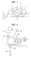
- This invention relates to a charging member, and a process cartridge and an electrophotographic apparatus both of which have the charging member.
- Image forming apparatus that employ an electrophotographic system, called electrophotographic apparatus, commonly have an electrophotographic photosensitive member, a charging means, an exposure means, a developing means and a transfer means.
- a system is primarily employed in which a voltage (a DC voltage only or a voltage created by superimposing an AC voltage on a DC voltage) is applied to a charging member disposed in contact with, or in proximity to, the surface of an electrophotographic photosensitive member, to charge the surface of the electrophotographic photosensitive member electrostatically.
- a voltage a DC voltage only or a voltage created by superimposing an AC voltage on a DC voltage
- the voltage created by superimposing an AC voltage on a DC voltage is employed as the voltage applied to the charging member
- an AC power source is necessary which requires a large-sized electrophotographic apparatus or brings about an increase in cost, thus a larger power consumption may result, and higher levels of ozone may be produced because of the use of alternating current which will cause a lowering of the durability (running performance) of the charging member or electrophotographic photosensitive member.
- the voltage to be applied to the charging member is only a DC voltage.
- a contact type charging system is preferably used.
- the charging member In the case of such a contact type charging member, the charging member is kept in contact with the electrophotographic photosensitive member by the pressing force of springs or the like, and is rotated following the rotation of the latter. In many cases, the force by which the charging member is kept in contact with a member to be charged is constant.
- C-set C-set deformation
- C-set areas may appear as horizontal black lines and/or horizontal white lines (C-set images) in the longitudinal direction when, e.g., halftone images are reproduced. This is known to be due to non-uniform charging of the charging member. It has also come to light that the above C-set images tend to occur especially where the voltage applied to the charging member is only a DC voltage.
- Patent Document 1 discloses that an elastic layer is incorporated with a copolymer of ethylene and propylene which contains as a copolymer component a diene component having an iodine value of from 23 to 32, whereby the C-set can be remedied.
- Patent Document 1 discloses that the technique disclosed in Patent Document 1 can not sufficiently remedy the C-set under severer conditions, e.g., under such circumstances that the voltage applied to the charging member is only a DC voltage.
- JP 2003 1 621 06 discloses an electrically conductive material for electrically conductive roll, dispersed liquid containing the same, electrically conductive roll and coating composition for electrically conductive roll.
- JP 2003 131429 discloses a method of manufacturing toner.
- JP 2000 181243 A discloses a charge relating member such as a transfer roller for an electrophotographic system, wherein composite metal oxide particles and carbon are dispersed in the resin of the outermost layer of said member.
- JP 11 231014 A discloses a charge imparting member for an electrophotographic system, said member containing composite metal oxide particles and a carbon black comprising volatile matter.
- JP 08 069155 A discloses magnetic particles for a charging means in an electrophotographic system, wherein said particles may also contain iron oxide and magnesium oxide.
- JP 2003 316111 A discloses a charging member comprising in its outermost conductive resin layer two kinds of particles, where the two kinds are different in particle size.
- an object of the present invention is to provide a charging member which can contribute to good image reproduction free of image defects (in particular, C-set images) even when it is used in an electrophotographic apparatus set in a state where it is very difficult to solve the technical problem of C-set, as in the electrophotographic apparatus in which the voltage applied to the charging member is only a DC voltage, and also to provide a process cartridge and an electrophotographic apparatus both of which have such a charging member.
- the present invention is directed to a charging member as claimed in claim 1.
- the present invention also provides a process cartridge as described in claim 14 and an electrophotographic apparatus as described in claim 15 both of which have the above charging member.
- the other claims relate to further developments.
- the present inventors have made many studies on the problems discussed above. As a result, as a means for keeping the C-set images from occurring, they have found the constitution of a charging member that can simultaneously achieve two points, which are to lessen the level of C-set deformation causative of C-set images and to render C-set areas invisible on images even when they are present. Thus, they have accomplished the present invention.
- carbon black When incorporated in rubbers, resins, elastomers or the like, carbon black is known to render them conductive and also reinforce them.
- carbon black and materials such as rubbers or resins used in the outermost layer are combined strongly with each other, and the strength can be enhanced.
- the outermost layer is incorporated only with carbon black, the effect of the reinforcement may come too large depending on its quantity, so that the surface of the charging member may have such a high hardness as to cause difficulties such that the charging member comes into faulty contact with the electrophotographic photosensitive member or cannot be suitably rotated and slips.
- any contamination components having remained on the electrophotographic photosensitive member without being transferred to paper or the like tend to be crushed by the charging member, so that contaminants adhere to the charging member surface, resulting in a lowering of durability of the charging member.
- Such difficulties may also come about.
- the carbon black is added in a smaller amount to lower the reinforcement effect, it is difficult to provide the surface layer with desired conductivity. That is, it has not been able to find the addition amount of carbon black that satisfies both the reinforcement effect and conductivity at a high level in the surface layer.
- the present inventors have made further many studies.
- the outermost layer of the charging member may be so constituted that first segments formed of composite particles comprising first metal oxide particles coated with carbon black and second segments formed of second metal oxide particles are present in a matrix comprising a binder, thereby achieving at a high level both of flexible deformation properties of the outermost layer at the time of application of external force to the outermost layer and restoration properties of the outermost layer at the time of removal of the external force.
- the present invention It is unclear why the flexible deformation properties and the restoration properties can be achieved at a high level by the above constitution, but is presumed below.
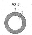
- Fig. 4 is a view diagrammatically illustrating a cross section of an outermost layer 400 according to the present invention.
- reference numeral 401 denotes a binder as a matrix; 403, a first segment formed of a composite particle comprised of a first metal oxide particle 301 coated with carbon black 303 as shown in Fig. 3 ; and 405, a second segment formed of a second metal oxide particle. Then, the first segment 403 chemically combines the first metal oxide particle with the surrounding binder through the carbon black 303. Thus, the position of the first segment in the outermost layer is substantially fixed.
- the second segment 405 has almost no property of combining with the binder, and hence its position in the outermost layer is relatively rich in freedom.
- the second segment 405 when external force is applied to the outermost layer, the second segment 405, the position of which is not definitely fixed to the binder because of its low affinity with the binder, changes flexibly in its position in the outermost layer due to the external force applied to the outermost layer, and thereby absorbs the external force.
- the first segment 403, the relative position of which is stationary to the binder brings about restoration properties in the outermost layer at the time of removal of the external force from the outermost layer.
- the charging member surface is considered to maintain a low hardness and at the same time to lessen the C-set deformation level.
- the cross section of the outermost layer in the present invention may be observed on a TEM (transmission electron microscope) photograph of a thin piece prepared by curing a cut piece (inclusive of the outermost layer) of the charging member with an acrylic resin and cutting the cured piece with a microtome.
- TEM transmission electron microscope
- charging members containing in their outermost layers particles similar to the composite particles according to the present invention are disclosed in Japanese Patent Applications Laid-open No. 2003-162106 and No. 2004-126064 .
- Japanese Patent Application Laid-open No. 2003-162106 proposes a conductive roller which contains composite particles comprising organic polymeric material base particles coated with conductive carbon black.
- conductive particles are added which comprise base particles with carbon black laid thereon whose base particles are formed of an organic high polymer such as a polyethylene resin or an acrylic resin and have a larger particle diameter than the carbon black, and that carbon black is held on giant particles in that way to prevent the carbon black itself from agglomerating and, in such constitution, the base particles come into contact with each other in the form of beads to form a network, where the carbon black stands dispersed unevenly in a conductive layer, and may be added in a small amount to achieve a high conductivity.
- the carbon black stands dispersed unevenly as in what is disclosed in the above Japanese Patent Application Laid-open No. 2003-162106 , it is considered that the outermost layer structure described above which the present invention aims at has not been achieved.
- Japanese Patent Application Laid-open No. 2004-126064 also proposes a conductive member which contains composite particles comprised of inorganic oxide particles surface-covered with surface layers having electron conductivity.
- a conductive member which contains composite particles comprised of inorganic oxide particles surface-covered with surface layers having electron conductivity.
- it has no disclosure as to the incorporation of the second metal oxide particles according to the present invention and the operation and effect to be brought about thereby, and it is considered that the outermost layer structure according to the present invention has not been achieved.
- the charging member according to an embodiment of the present invention is a charging member having a cover layer on a support, and the charging member has an outermost layer containing i) composite particles comprising first metal oxide particles coated with carbon black, ii) second metal oxide particles and iii) a binder.
- That the charging member electrifies the surface of the electrophotographic photosensitive member means that discharge occurs from the charging member to the surface of the electrophotographic photosensitive member causing charge transfer.
- point Y a point at which an extension of a radius of a charging member passing on a certain point X on the charging member surface intersects the electrophotographic photosensitive member surface
- the discharge takes place when a potential difference Vxy between the point X and the point Y exceeds a Paschen's discharge limit voltage (discharge start voltage) Vpa, electric charges ⁇ Q transfer to the electrophotographic photosensitive member surface, and reverse electric charges - ⁇ Q transfer to the charging member surface.
- the total sum of ⁇ Q corresponds to the electric charges Q accumulated on the surface of the electrophotographic photosensitive member.
- the electric charges ⁇ Q transferring due to discharge depend on G, i.e., the gap between the charging member and the electrophotographic photosensitive member. More specifically, it is considered that the deformation at a C-set area inevitably produces a gap difference between the normal charging member surface area and the C-set deformation area to make a difference in the ⁇ Q, and hence the C-set images (horizontal black lines and/or horizontal white lines) may occur.
- the present invention makes use of the metal oxide particles (first metal oxide particles) in the composite particles in order to obtain the effect of increasing the dielectric constant of the outermost layer.
- the dielectric constant is also known to change greatly, depending on the distribution of conductive portions in the layer. Studies made by the present inventors have revealed that if the outermost layer has the structure having segments as described above, it is possible to increae its dielectric constant. In order to perform such structural control, it is necessary for the outermost layer to be further incorporated with second particles in addition to the composite particles. In particular, as the particles, it is preferable to use metal oxide particles superior in dispersibility into rubbers, resins, elastomers and so forth.
- the composite particles may preferably have an average particle diameter of from 1 nm to 1,000 nm, and more preferably from 5 nm to 500 nm. Within this range, the outermost layer reinforcement effect in the above structure is sufficiently brought about. It is also easy to prevent the dispersibility of composite particles in the outermost layer from deteriorating due to agglomeration among the composite particles.
- the composite particles may have any shape of spherical, granular, polygonal, acicular, spindlelike, rice-grain-like, flaky, scaly and platelike shapes.
- a spherical or granular shape is preferred in order to improve the C-set properties.
- the first metal oxide particles may be particles of metal oxide or composite metal oxide, and may specifically include particles of zinc oxide, tin oxide, indium oxide, titanium oxide (such as titanium dioxide or titanium monoxide), iron oxide, silica, alumina, magnesium oxide, zirconium oxide, strontium titanate, calcium titanate, magnesium titanate, barium titanate and calcium zirconate. They may more preferably be particles of silica, alumina, titanium oxide, zinc oxide, magnesium oxide, iron oxide, strontium titanate, calcium titanate, magnesium titanate, barium titanate and calcium zirconate.
- the shape of the composite particles depends greatly on the particle diameter and shape of the first metal oxide particles. Accordingly, the first metal oxide particles may also preferably have an average particle diameter of from 1 nm to 1,000 nm, and more preferably from 5 nm to 500 nm.
- the first metal oxide particles may have any shape of spherical, granular, polygonal, acicular, spindlelike, rice-grain-like, flaky, scaly and platelike shapes.
- a spherical or granular shape is preferred in order to improve the C-set properties.
- furnace black As the carbon black with which the first metal oxide particles are coated, furnace black, KETJEN BLACK and channel black are preferably used.
- it may include granular acetylene black available from Denki Kagaku Kogyo Kabushiki Kaisha; HS-500, ASAHI THERMAL FT, and ASAHI THERMAL MT, available from Asahi Carbon Co., Ltd.; KETJEN BLACK, available from Lion Akzo Co., Ltd.; VULCAN XC-72, REGAL 400R, and MONARCH 1300, available from Cabot Corporation; and COLOR BLACK FW200, SPECIAL BLACK 4, PRINTEX 150T, PRINTEX 140T, and PRINTEX U, available from Degussa Japan Ltd.). These may be used alone or in combination.
- the first metal oxide particles may preferably be those having been surface-treated with a surface treating agent. This enables the carbon black to adhere more strongly to the first metal oxide particle surfaces. Thus, the carbon black can be prevented from, e.g., being liberated when the composite particles are dispersed in rubbers, resins, elastomers or the like, and the effect of improving the C-set properties can be further brought about.
- organosilicon compounds such as alkoxysilanes, fluoroalkylsilanes and polysiloxanes, various coupling agents of a silane type, a titanate type, an aluminate type and a zirconate type, and oligomers or polymeric compounds. It is more preferable to use organosilicon compounds such as alkoxysilanes and polysiloxanes, and various coupling agents of a silane type, a titanate type, an aluminate type and a zirconate type, and still more preferable to use organosilicon compounds.
- organosilicon compounds may be exemplified by an alkoxysilane represented by the formula (1), an organosilane compound produced from the alkoxysilane, a polysiloxane represented by the formula (2), a modified polysiloxane represented by the formula (3), a terminal-modified polysiloxane represented by the formula (4), a fluoroalkylsilane represented by the formula (5), and a mixture of any of these.
- R a -Si-X 4-a (1)
- the alkoxysilane may specifically include methyltriethoxysilane, dimethyldiethoxysilane, phenyltriethoxysilane, diphenyldiethoxysilane, dimethyldimethoxysilane, methyltrimethoxysilane, phenyltrimethoxysilane, diphenyldimethoxysilane, isobutyltrimethoxysilane and decyltrimethoxysilane.
- alkoxysilanes such as methyltriethoxysilane, methyltrimethoxysilane, dimethyldimethoxysilane, isobutyltrimethoxysilane and phenyltriethoxysilane, or organosilane compounds produced from the alkoxysilanes.
- R 1 :-H,-CH 3 v:15 ⁇ 450 (R 3 , R 6 and R 7 may be the same or different.)
- the polysiloxane may include polysiloxanes having a methylhydrogensiloxane unit, polyether modified polysiloxanes, and terminal carboxylic acid modified polysiloxanes, modified with a carboxylic acid(s) at a terminal(s).
- the fluoroalkylsilane may specifically include trifluoropropyltrimethoxysilane, tridecafluorooctyltrimethoxysilane, heptadecafluorodecyltrimethoxysilane, heptadecafluorodecylmethyldimethoxysilane, trifluoropropylethoxysilane, tridecafluorooctyltriethoxysilane and heptadecafluorodecyltriethoxysilane.
- the silane type coupling agent may include vinyltrimethoxysilane, vinyltriethoxysilane, ⁇ -aminopropyltriethoxysilane, ⁇ -glycidoxypropyltrimethoxysilane, ⁇ -mercaptopropyltrimethoxysilane, ⁇ -methacryloxypropyltrimethoxysilane, N- ⁇ -(aminoethyl)- ⁇ -aminopropyltrimethoxysilane, ⁇ -glycido,xypropylmethyldimethoxysilane and ⁇ -chloropropyltrimethoxysilane.
- the titanate coupling agent may include isopropyltristearoyl titanate, isopropyltri(dioctyl pyrophosphate) titanate, isopropyltri(N-aminoethyl aminoethyl) titanate, tetraoctylbis(ditridecyl phosphate) titanate, tetra(2,2-diallyloxymethyl-1-butyl)bis(ditridecyl) phosphate titanate, bis(dicotyl pyrophosphate) oxyacetate titanate, and bis(dicotyl pyrophosphate) ethylene titanate.
- the aluminate type coupling agent may include acetoalkoxyaluminum diisopropylate, aluminum diisopropoxymonoethyl acetoacetate, aluminum trisethyl acetoacetate, and aluminum trisacetyl acetonate.
- the zirconate type coupling agent may include zirconium tetrakisacetyl acetonate, zirconium dibutoxybisacetyl acetonate, zirconium tetrakisethyl acetoacetate, zirconium tributoxymonoethyl acetoacetate, and zirconium tributoxyacetyl acetonate.
- oligomers those having a molecular weight of from 300 or more to less than 10,000 are preferable.
- polymeric compounds those having a molecular weight of from 10,000 or more to about 100,000 are preferable. Taking into account uniform coat treatment on the first metal oxide particles, oligomers or polymeric compounds which are liquid, or soluble in water or various solvents are preferable.
- the surface treating agent may preferably be in a coat weight (coverage) of from 0.01 to 15.0% by weight based on the weight of the first metal oxide particles. If it is less than 0.01% by weight, it may be difficult to adhere the carbon black to the first metal oxide particles. If it is in a coat weight of 15.0% by weight, the carbon black can be adhered strongly to the first metal oxide particles and in a sufficient quantity, and hence it is meaningless to coat the first metal oxide particles in a coat weight of more than that. It may more preferably be in a coat weight of from 0.02 to 12.5% by weight, and most preferably from 0.03 to 10.0% by weight.
- the volume resistivity of the composite particles in the present invention may arbitrarily be controlled to a value intermediate between the volume resistivity of the carbon black used in adhering to the first metal oxide particles and the volume resistivity of the first metal oxide particles. Specifically, it may be from 1.0 ⁇ 10 to 1.0 ⁇ 10 8 ⁇ cm, and preferably from 5.0 ⁇ 10 to 5.0 ⁇ 10 7 ⁇ cm.
- the carbon black may be adhered to the first metal oxide particles in a weight of from 1 to 500 parts by weight based on 100 parts by weight of the latter. If it is in a weight of less than 1 part by weight, it is difficult for the resultant composite particles to have a low electrical resistance. If it is in a weight of more than 500 parts by weight, the effect of lowering the electrical resistance can sufficiently be exhibited, and hence it is meaningless to adhere the carbon black in a weight of more than 500 parts by weight.
- the composite particles may be obtained by mixing the first metal oxide particles and the carbon black.
- the carbon black may be adhered to the first metal oxide particles by first surface-treating the first metal oxide particles and then mixing the surface-treated first metal oxide particles and the carbon black.
- the surface treatment of the first metal oxide particles may be carried out by mechanically mixing and agitating the first metal oxide particles and the surface treating agent or a solution of the surface treating agent, or by mechanically mixing and agitating the first metal oxide particles and the surface treating agent or a solution of the surface treating agent while the latter is sprayed on the former.
- part of the alkoxysilane or fluoroalkylsilane may be applied as an organosilane compound formed from the alkoxysilane or a fluorine-containing organosilane compound formed from the fluoroalkylsilane as a result of going through the coating step.
- the subsequent adhesion of carbon black is by no means affected.
- an apparatus capable of applying shear force to powder layers is preferred.
- apparatus are usable which can carry out shearing, spatulation and compression simultaneously, as exemplified by a wheel type kneading machine, a ball type kneading machine, a blade type kneading machine and a roll type kneading machine.
- the wheel type kneading machine is more effectively usable.
- drying or heat treatment may optionally be carried out.
- the surface treatment of the first metal oxide particles a method is available in which the first metal oxide particles and the surface treating agent are mixed and dispersed in a suitable solvent to adhere the surface treating agent to particle surfaces.
- a suitable solvent such as a ball mill, a sand mill, a paint shaker, Daino mill and Pearl mill are usable.
- the solvent is removed from the resultant fluid dispersion to allow the surface treating agent to stick to particle surfaces.
- heat treatment may further optionally be carried out.
- a catalyst for accelerating the reaction may be added to the fluid mixture.
- the particles having been surface-treated may optionally be subjected to pulverization.
- the first metal oxide particles may be those the particle surfaces of which have previously been coated with an intermediate coat material consisting of at least one selected from a hydroxide of aluminum, an oxide of aluminum, a hydroxide of silicon and an oxide of silicon. This is because there are cases in which the adhesive force between the first metal oxide particles and the carbon black can thereby be made stronger.
- Such an intermediate coat material may preferably be in a coat weight (coverage) of from 0.01 to 20% by weight. If it is in a coat weight of less than 0.01% by weight, the effect of improving the adhesion of carbon black is not obtainable in some cases. Even if it is in a coat weight of more than 20% by weight, the effect of further improving the adhesion of carbon black is not obtainable, and hence it is meaningless to be in a coat weight of more than that.
- the second metal oxide particles may preferably have an average particle diameter of from 1 nm to 1,000 nm, and more preferably from 5 nm to 500 nm. Within this range, the outermost layer reinforcement effect due to the above structure can sufficiently be brought about. Also, the second metal oxide particles can be kept from agglomerating, and their dispersibility in the binder in the outermost layer can be suitably controlled.
- the second metal oxide particles may preferably be those having been surface-treated.
- the surface treatment may include, in addition to the same surface treatment as that for the first metal oxide particles described above, surface treatment with a fatty acid or a fatty acid metal salt.
- any of saturated or unsaturated fatty acids may be used, and those having 12 to 22 carbon atoms are preferred.
- the fatty acid metal salt salts of saturated or unsaturated fatty acids with metals are usable, which may include salts of fatty acids having 12 to 22 carbon atoms with alkaline earth metals such as magnesium, calcium, strontium and barium, alkali metals such as lithium, sodium and potassium, or metals such as zinc, aluminum, copper, iron, lead and tin.
- the surface treatment of the metal oxide particles in the present invention may preferably be surface treatment with an organosilicon compound such as an alkoxysilane or a polysiloxane. This is because such a compound is suitably adherent to the metal oxide particle surfaces, and at the same time effective in improving the dispersibility of the metal oxide particles in rubbers, resins, elastomers or the like.
- an organosilicon compound such as an alkoxysilane or a polysiloxane.
- the surface treating agent may preferably be in a coat weight (coverage) of from 0.01 to 15.0% by weight. Within this range, it can provide the second metal oxide particles with sufficient dispersibility. It may more preferably in a coat weight of from 0.02 to 12.5% by weight, and most preferably from 0.03 to 10.0% by weight.
- the second metal oxide particles may preferably have a dielectric constant of 30 or more. This is because it is preferable to increase the dielectric constant of the outermost layer as described previously. Accordingly, it is more preferable to select the second metal oxide particles from particles of titanium oxide, strontium titanate, calcium titanate and barium titanate.
- the second metal oxide particles may be surface-treated by the same methods as those for the first metal oxide particles described previously.
- the method in which mixing and dispersion are effected in the solvent is particularly preferable.
- This method enables strong and uniform treatment of the second metal oxide particle surfaces to be strongly and uniformly treated, and can greatly improve the dispersibility of the second metal oxide particles, making it easy to achieve the outermost layer structure described above which the present invention aims at.
- both of the first and second metal oxide particles are insulating particles.
- the insulating particles refer to those having a volume resistivity of more than 1 ⁇ 10 8 ⁇ cm.
- the metal oxide particles are insulating, the conductive paths in virtue of the carbon black can be controlled, and a higher dielectric constant can be established in the outermost layer structure which the present invention aims at.
- the composite particles and second metal oxide particles in the outermost layer may preferably be in a weight ratio (composite particles/second metal oxide particles) of from 0.01 to 100, more preferably from 0.1 to 50, still more preferably from 0.2 to 15, and particularly preferably from 0.2 to 3.9. Within this range, it is easy to achieve the outermost layer structure which the present invention aims at, and a high effect can be brought about against the C-set images.
- a proportion of the total weight of the composite particles and second metal oxide particles in the outermost layer to the outermost layer binder may preferably be from 5 to 200% by weight, and more preferably from 10 to 150% by weight. Within this range, it is easy to achieve the outermost layer structure which the present invention aims at, and a high effect can be brought about against the C-set images
- any of layers may be employed which are conventionally known and have variety of structures, including layers formed of, e.g., resins, rubbers (natural rubbers, which may be subjected to vulcanization treatment, or synthetic rubbers) and elastomers such as thermoplastic elastomers, used as binding materials.
- the resins may include fluorine resins, polyamide resins, acrylic resins, polyurethane resins, silicone resins, butyral resins, a styrene-ethylene butylene-olefin copolymer (SEBC) and an olefin-ethylene butylene-olefin copolymer (CEBC).
- SEBC styrene-ethylene butylene-olefin copolymer
- CEBC olefin-ethylene butylene-olefin copolymer
- the synthetic rubbers may include an ethylene-propylene-diene copolymer (EPDM), styrene-butadiene copolymer rubber (SBR), silicone rubbers, urethane rubbers, isoprene rubber (IR), butyl rubber (BR), acrylonitrile-butadiene copolymer rubber (NBR), chloroprene rubber (CR), acrylic rubbers and epichlorohydrin rubbers.
- EPDM ethylene-propylene-diene copolymer
- SBR styrene-butadiene copolymer rubber
- silicone rubbers silicone rubbers
- urethane rubbers urethane rubbers
- IR isoprene rubber
- BR butyl rubber
- NBR acrylonitrile-butadiene copolymer rubber
- CR chloroprene rubber
- the thermoplastic elastomers may include polyolefin type thermoplastic elastomers, urethane type thermoplastic elastomers, polystyrene type thermoplastic elastomers, fluorine rubber type thermoplastic elastomers, polyester type thermoplastic elastomers, polyamide type thermoplastic elastomers, polybutadiene type thermoplastic elastomers, ethylene vinyl acetate type thermoplastic elastomers, polyvinyl chloride type thermoplastic elastomers, and chlorinated polyethylene type thermoplastic elastomers.
- Any of the above may be used alone, or in the form of a mixture or a copolymer.
- two or more cover layers may be provided on the support.
- the support of the charging member may at least have conductivity (conductive support).
- conductive support a support made of a metal (or made of an alloy) such as iron, copper, stainless steel, aluminum or nickel may be used.
- plating or the like may be applied to the surface of any of these supports as long as its conductivity is not impaired.
- a cover layer having conductivity and elasticity may preferably be provided between a cover layer serving as the outermost layer (hereinafter also “surface cover layer”) and the support, from the viewpoint of improving the supply of electricity to that electrophotographic photosensitive member and establishing uniform close contact between that electrophotographic photosensitive member and the charging member.
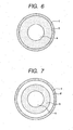
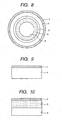
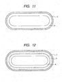
- Examples of the layer structure of the charging member are shown in Figs. 5 to 12 .
- the charging member shown in Fig. 5 is a roller-shaped charging member, and is of a single-layer structure, having a support a, and a surface cover layer c formed on the support a.
- the charging member shown in Fig. 6 is a roller-shaped charging member, and is of a double-layer structure, having a support a, an elastic cover layer b formed on the support a, and a surface cover layer c formed on the elastic cover layer b.
- the charging member shown in Fig. 7 is a roller-shaped charging member, and is of a triple-layer structure, provided with a resistance layer (a kind of cover layer) d between the elastic cover layer b and the surface cover layer c of the charging member shown in Fig. 6 .
- the charging member shown in Fig. 8 is a roller-shaped charging member, and is of a four-layer structure, provided with a second resistance layer (a kind of cover layer) between the resistance layer d and the surface cover layer c of the charging member shown in Fig. 7 .
- the charging member of the present invention may preferably have the shape of a roller, but may have various shapes such as, as exemplified in Figs. 9 to 12 , the shape of a sheet, the shape of a belt, the shape of a film and the shape of a plate, which may each also have the layer structure described above.
- the roller-shaped charging member is called "charging roller”.
- the roller-shaped charging member i.e., the charging roller may be formed in what is called a crown shape, a shape in which the roller is thickest at the middle in its lengthwise direction and is thinner toward both ends in the lengthwise direction. This is preferable from the viewpoint of establishing uniform close contact between the charging roller and the electrophotographic photosensitive member.
- the charging roller commonly comes into contact with the electrophotographic photosensitive member in the state that given pressing force is applied to both ends of the support, where the pressing force is small at the middle in the lengthwise direction and becomes larger toward both ends in the lengthwise direction. Hence, density non-uniformity may occur between images corresponding to the middle and images corresponding to both ends.
- the crown shape is formed in order to prevent such density non-uniformity.
- the difference between an external diameter at the middle portion and external diameters at positions 90 mm away from the middle portion may preferably be from 30 ⁇ m to 200 ⁇ m. If it is smaller than 30 ⁇ m, a state is apt to come about in which the roller comes in contact at the end portions and not at the middle portion. If it is larger than 200 ⁇ m, in reverse a state is apt to come about in which the roller comes in contact at the middle portion but not at the end portions.
- a material having a high releasability may preferably be used in the surface cover layer so that the charging member may not contaminate the electrophotographic photosensitive member and other members.
- a resin may preferably be used as a binding material of the surface cover layer.
- the outermost layer may contain:
- the additional particles that may be incorporated in the surface cover layer are roughly grouped into conductive particles and insulating particles.
- the "conductive particles” are meant to be particles having a volume resistivity of 1 ⁇ 10 8 ⁇ cm or less
- the "insulating particles” are meant to be particles having a volume resistivity of more than 1 ⁇ 10 8 ⁇ cm.
- the conductive particles may include, e.g., particles of carbon black, tin oxide, titanium oxide, zinc oxide, barium sulfate, copper, aluminum or nickel.
- the insulating particles may include, e.g., particles of high-molecular compounds, as exemplified by particles of resins such as polyamide resins, silicone resins, fluorine resins, acrylic or methacrylic resins, styrene resins, phenol resins, polyester resins, melamine resins, urethane resins, olefin resins, epoxy resins, and copolymers, modified products or derivatives of these; particles of rubbers such as an ethylene-propylene-diene copolymer (EPDM), styrene-butadiene copolymer rubber (SBR), silicone rubbers, urethane rubbers, isoprene rubber (IR), butyl rubber (BR), acrylonitrile-butadiene copolymer rubber (NBR), chloroprene rubber (CR) and epichlorohydrin rubbers; and particles of thermoplastic elastomers such as polyolefin type thermoplastic elastomers, ure
- Other insulating particles may include particles of barium sulfate, molybdenum disulfide, calcium carbonate, magnesium carbonate, dolomite, talc, kaolin clay, mica, aluminum hydroxide, magnesium hydroxide, zeolite, wollastonite, diatomaceous earth, glass beads, bentonite, montmorillonite, asbestos, hollow glass balloons, graphite, rice hull, organometallic compounds, and organometallic salts. Also particles of iron oxides such as ferrite, magnetite and hematite, and activated carbon are usable.
- the ferrite may include, e.g., ferrite described in " Electronic Material Series, Ferrite” (Maruzen Co., Ltd.; published September 10, 1997, Fifth Editi on). Specifically, MnFe 2 O 4 , Fe 2 O 4 , ZnFe 2 O 4 , MgFe 2 O 4 and ⁇ -Fe 2 O 4 may be exemplified.
- the activated carbon may include activated carbon described in " New Edition, Activated Carbon - Basis and Application” (Kodansha Ltd.; published October 20, 1992, Second Editi on). Specifically, wood activated carbon, coconut shell activated carbon, and coal activated carbon may be exemplified.
- any of these particles may be used alone or in combination, and may be those having been surface-treated, modified, functional-group- or molecular-chain-introduced, or coated.
- the particles may preferably be subjected to surface treatment.
- the surface treatment of particles the surface treatment methods may be used which have been described in respect of the above first metal oxide particles and/or second metal oxide particles.
- a release agent may also be incorporated in the surface cover layer. Incorporation of the release agent in the surface cover layer can reduce any adhesion of dirt to the surface of the charging member, and hence improve durability (running performance) of the charging member. Such incorporation can smoothen relative movement between the charging member and the electrophotographic photosensitive member, and hence ressen irregular movement such as stick slip, so that irregular wear of the surface of the charging member, noise (abnormal sound) and so forth can be kept from occurring.
- the release agent incorporated in the surface cover layer is a liquid, it acts also as a leveling agent when the surface cover layer is formed.
- release agents are those utilizing low surface energy and those utilizing slidability, and their states are liquid or solid.
- solid lubricants the following are usable, e.g., substances described in Solid Lubricant Handbook (publisher: K.K. Saiwai Shobo Co.; published March, 15, 1982, Second Editi on), which are specifically metal oxides such as graphite, graphite fluoride, molybdenum disulfide, tungsten disulfide, boron nitride and lead monoxide.
- Compounds containing silicon or fluorine in their molecules may be used in an oil form or a solid form (releasing resin or powder, or a polymer into part of which a moiety having releasability has been introduced).
- the release agent may further include waxes and higher fatty acids (inclusive of salts or esters and other derivatives thereof).
- a binding material an elastomer such as a rubber or a thermoplastic elastomer.
- a rubber in particular, a synthetic rubber.
- the synthetic rubber from the viewpoint of uniformity in resistance, it is preferable to use a polar rubber.
- the polar rubber may include NBR and epichlorohydrin rubbers.
- a rubber containing epichlorohydrin rubber it is more preferable to use a rubber containing epichlorohydrin rubber as a main component.
- the elastic cover layer may also preferably have a volume resistivity of from 10 2 to 10 8 ⁇ cm in an environment of 23°C/50%RH. If the elastic cover layer has a volume resistivity of more than 10 8 ⁇ cm, a difficulty may come about such that the charging ability required for the charging member may lower to tend to cause C-set images more conspicuously. If on the other hand the elastic cover layer has a volume resistivity of less than 10 2 ⁇ cm, the whole charging member may have excessively low resistance so that it may be difficult to prevent leakage due to pinholes or scratches of the surface of the electrophotographic photosensitive member, the member to be charged.
- the ethylene oxide unit in the epichlorohydrin rubber may preferably be in a content of from 55 to 85 mol%. If it is in a content of less than 55 mol%, the above volume resistivity is not achievable. If on the other hand it is in a content of more than 85 mol%, not only a difficulty may come about such that the elastic cover layer may have a large C-set deformation level, but also a problem may arise such that the polymer tends to be crystallized to increase the electrical resistnce of the elastic cover layer.
- additives such as a softening oil and a plasticizer may be added to the elastic cover layer.
- the elastic cover layer may also be made to serve as the surface layer, i.e., a surface cover layer of the charging member.
- a surface cover layer of the charging member i.e., a softening oil and a plasticizer
- this elastic cover layer it is preferable for this elastic cover layer not to be the surface layer of the charging member, in order to prevent the additives from oozing out on the surface of the charging member.
- the conductivity (volume resistivity) of the elastic cover layer may be controlled by appropriately adding to the above binding material a conducting agent such as carbon black, a conductive metal oxide, an alkali metal salt or an ammonium salt.
- a conducting agent such as carbon black, a conductive metal oxide, an alkali metal salt or an ammonium salt.
- the epichlorohydrin rubber component it is particularly preferable to use the ammonium salt.
- the epichlorohydrin rubber component when used, the volume resistivity is greatly influenced by the content of the ethylene oxide unit as stated above.
- one or two or more resistance layers may also be provided between the elastic cover layer and the surface cover layer, from the viewpoint of firmly preventing the additives from oozing out.
- the resistance layer may preferably have a volume resistivity of from 10 2 ⁇ cm or more to 10 16 ⁇ cm or less. If the resistance layer has a volume resistivity above this range, difficulties may come about such that the charging ability required for the charging member may lower to tend to cause C-set images more conspicuously or that the ability to perform uniform charging (charging uniformity) may lower.
- the resistance layer has a volume resistivity below the above range, it may be difficult to prevent leakage due to pinholes or scratches of the surface of the electrophotographic photosensitive member, the member to be charged.
- one or two or more types of conductive particles may be incorporated in the resistance layer.
- materials having various functions may also appropriately be incorporated in the surface cover layer, elastic cover layer and resistance layer.
- Such materials may include, e.g., antioxidants such as 2-mercaptobenzimidazole, and lubricants such as stearic acid and zinc stearate.
- the surfaces of the surface cover layer, elastic cover layer and resistance layer may also be subjected to surface treatment.
- the surface treatment may include, e.g., surface working treatment making use of ultraviolet rays or electron rays, and surface modification treatment in which a compound is adhered to, and/or impregnated into, the surface.
- the above surface cover layer, elastic cover layer and resistance layer may be formed by applying a sheet-shaped or tube-shaped layer formed beforehand in a given thickness to the support or underlying layer, or covering the support or underlying layer with, a sheet-shaped or tube-shaped layer formed beforehand in a given thickness, or by coating such as electrostatic spray coating or dip coating.
- a method may also be used in which the layer is roughly formed by extrusion and thereafter subjected to shape adjustment by grinding or polishing, or a method may still also be used in which a material is cured and molded in a mold into a given shape.
- any solvent will suffice the solvent used in a coating solution as long as it is capable of dissolving the binding material.
- it may include alcohols such as methanol, ethanol and isopropanol; ketones such as acetone, methyl ethyl ketone and cyclohexanone; amides such as N,N-dimethylformamide and N,N-dimethylacetamide; sulfoxides such as dimethyl sulfoxide; ethers such as tetrahydrofuran, dioxane, and ethylene glycol monomethyl ether; esters such as methyl acetate and ethyl acetate; aliphatic halogenated hydrocarbons such as chloroform, ethylene chloride, dichloroethylene, carbon tetrachloride, and trichloroethylene; and aromatic compounds such as benzene, toluene, xylene, ligroine, chlorobenzene
- alcohols such as methanol,
- cover layer material As methods for dispersing particles in a cover layer material, known methods may be used.
- the cover layer material and the particles may be mixed by means of Ribbon blender, Nauta mixer, Henschel mixer, Super mixer or the like, or by means of Banbury mixer, a pressure kneader or the like.
- the solvent, the cover layer materials and the particles may be mixed, and dispersed using a conventionally known fluid dispersion means such as the ball mill, sand mill, paint shaker, Daino mill or Pearl mill mentioned previously.
- the microhardness of the charging member surface in the present invention is measured with a microhardness meter MD-1 Model (manufactured by Koubunshi Keiki Co., Ltd.) in a peak hold mode in an environment of 23°C/55%RH. More specifically, the charging member is placed on a metal plate with blocks preventing rolling. The measuring terminal end is precisely pressed against the charging member surface toward the center of the charging member from the direction vertical to the metal plate, and 5 seconds after, the value is read out. The same process is carried out at 3 places in the peripheral direction of each of 30 to 40 mm positions from both rubber ends and the central portion of the charging member, i.e., at 9 places in total. An average value of the measured values is regarded as the microhardness.
- the average particle diameter of the particles in the present invention only primary particles from which secondarily agglomerated particles have been removed are observed for 100 particles on a transmission electron microscope (TEM), and their projected areas are determined. Circle-equivalent diameters of the projected areas obtained are calculated to find a volume-average particle diameter, which is regarded as the average particle diameter.
- TEM transmission electron microscope
- the volume resistivity of each of the surface cover layer, elastic cover layer and resistance layer is measured in an environment of 23°C/50%RH, using a resistance measuring instrument HIRESTA-UP, manufactured by Mitsubishi Chemical Corporation, under application of a voltage of 250 V for 30 seconds to a measurement object sample.
- a resistance measuring instrument HIRESTA-UP manufactured by Mitsubishi Chemical Corporation
- a layer of 2 mm in thickness is formed on a solid material to prepare the measurement object sample.
- an aluminum sheet is coated with the coating solution, and the coating formed is used as the measurement object sample.
- the volume resistivity of the particles is measured in an environment of 23°C/50%RH by using a resistance measuring instrument HIRESTA-UP, manufactured by Mitsubishi Chemical Corporation, and applying to a measurement object sample a voltage suited for the resistance of the measurement object sample (depending on region under which resistance to be measured falls, suitable voltage differs).
- the volume resistivity of particles in a conducting region is measured in an environment of 23°C/50%RH bu using a resistance measuring instrument LORESTA-GP, manufactured by Mitsubishi Chemical Corporation, under application of a voltage of 10 V to the measurement object sample.
- the amount of the measurement object sample to be used is appropriately adjusted taking into account the density of particles whose volume resistivity is to be measured. For example, when the volume resistivity of carbon black is measured, 0.5 g of the carbon black is used and compressed by applying a pressure of 10.1 MPa (102 kg f/cm 2 ) to prepare the measurement object sample.
- FIG. 1 The construction of an example of an electrophotographic apparatus provided with a process cartridge having an electrophotographic photosensitive member and the charging member of the present invention is schematically shown in Fig. 1 .
- reference numeral 1 denotes a cylindrical electrophotographic photosensitive member, which is rotatively driven around an axis 2 in the direction of an arrow at a given peripheral speed.
- the surface of the electrophotographic photosensitive member 1 being rotatively driven is uniformly electrostatically charged to a positive or negative, given potential through a charging means (in Fig. 1 , a roller-shaped charging member, i.e., a charging roller) 3.
- the electrophotographic photosensitive member thus charged is then exposed to exposure light (imagewise exposure light) 4L emitted from an exposure means (not shown) for slit exposure or laser beam scanning exposure.
- exposure light imagewise exposure light
- the electrostatic latent images thus formed on the surface of the electrophotographic photosensitive member 1 are developed with a toner contained in a developer in a developing means 5 into toner images. Then, the toner images thus formed and held on the surface of the electrophotographic photosensitive member 1 are successively transferred by the aid of a transfer bias given from a transfer means (such as a transfer roller) 6, onto a transfer material (such as paper) P fed from a transfer material feed means (not shown) to the part (contact zone) between the electrophotographic photosensitive member 1 and the transfer means 6 in such a manner as synchronized with the rotation of the electrophotographic photosensitive member 1.
- a transfer bias given from a transfer means (such as a transfer roller) 6
- a transfer material such as paper
- the transfer material P to which the toner images have been transferred is separated from the surface of the electrophotographic photosensitive member, is guided into a fixing means 8 where the toner images are fixed, and is then put out of the apparatus as an image-formed material (a print or a copy).
- the surface of the electrophotographic photosensitive member 1 from which the toner images have been transferred is subjected to removal of the developer (toner) remaining after the transfer, through a cleaning means (such as a cleaning blade) 7.
- a cleaning means such as a cleaning blade
- the electrophotographic photosensitive member surface is cleaned, and then repeatedly used for image formation.
- the surface of the electrophotographic photosensitive member 1 may be subjected to charge elimination by pre-exposure light before it is charged by the charging member 3.
- the apparatus may be constituted of a combination of plural components held in a housing and integrally joined as a process cartridge from among the constituents such as the above electrophotographic photosensitive member 1, charging member 3, developing means 5, transfer means 6 and cleaning means 7 so that the process cartridge is detachably mountable to the main body of the electrophotographic apparatus such as a copying machine or a laser beam printer.
- the electrophotographic photosensitive member 1, the primary charging means 3, the developing means 5 and the cleaning means 7 are integrally supported in the cartridge to form a process cartridge 9 that is detachably mountable to the main body of the apparatus through a guide means 10 such as rails installed in the main body of the electrophotographic apparatus.
- an electrophotographic photosensitive member may be employed which comprises, e.g., a cylindrical support (conductive support) and a photosensitive layer formed on the support, containing an inorganic photosensitive material and/or an organic photosensitive material.
- the electrophotographic photosensitive member 1 may further have a charge injection layer for charging the surface of the electrophotographic photosensitive member to a given polarity and potential.
- a developing system the developing means 3 may employ may include, e.g.; a jumping developing system, a contact developing system and a magnetic brush system.
- the contact developing system is particularly preferred for the purpose of preventing toner scatter.
- silica particles (average particle diameter: 17 nm; volume resistivity: 1.8 ⁇ 10 12 ⁇ cm) as first metal oxide particles
- 140 g of methylhydrogenpolysiloxane was added operating an edge runner mill, and mixed and agitated for 30 minutes at a linear load of 588 N/cm (60 kg/cm). Here the agitation was carried out at a speed of 22 rpm.
- the composite particles obtained had an average particle diameter of 15 nm and a volume resistivity of 1.8 ⁇ 10 2 ⁇ cm.
- This slurry was mixed for 30 minutes by means of a stirrer, and thereafter fed to a Visco mill 80% of whose effective internal volume was filled with glass beads 0.8 mm in average particle diameter, to effect wet disintegration at a temperature of 35 plus-minus 5°C.
- the slurry obtained by the wet disintegration was subjected to distillation under reduced pressure (bath temperature: 110°C; product temperature: 30 to 60°C; degree of reduced pressure: about 100 Torr) using a kneader to remove the toluene, followed by baking of the surface treating agent at 120°C for 2 hours.
- the particles having been subjected to the baking were cooled to room temperature, and thereafter pulverized by means of a pin mill.
- a mandrel of 6 mm in diameter and 252.5 mm in length, made of stainless steel was used as a support (conductive support). This was coated with a heat-curable adhesive (METALOC U-20, available from Toyokagaku Kenkyusho Co., Ltd.), followed by drying.
- METALOC U-20 available from Toyokagaku Kenkyusho Co., Ltd.
- This compound for an elastic cover layer was extruded onto the adhesive-coated support by means of an extruder and was so formed as to have the shape of a roller of about 10 mm in external diameter, and then subjected to vulcanization and curing of the adhesive, at 160°C for 1 hour in an electric oven. Thereafter, both ends of the rubber layer were cut through, followed by surface grinding working which was so carried out as to have the shape of a roller of 8.5 mm in external diameter.
- an elastic cover layer was formed on the support.
- the crown level (the difference between an external diameter at the middle portion and an external diameter at positions 90 mm away from the middle portion) was set to be 110 ⁇ m.
- methyl isobutyl ketone was so added as to adjust the solid content of the solution to 20% by weight.
- HDI trade name: DURANATE TPA-B80E, available from Asahi Chemical Industry Co. Ltd.
- IPDI trade name: BESTANATO B1370, available from Degussa-Hulls AG
- the elastic cover layer was dip-coated once with this surface cover layer coating fluid, followed by air drying at normal temperature for 30 minutes or more, subsequently drying for 1 hour by means of a circulating hot-air dryer set at 80°C, and further drying for 1 hour by means of a circulating hot-air dryer set at 160°C to form a surface cover layer on the elastic cover layer.
- the dip coating dipping time was 9 seconds
- the dip coating lifting rate was so set that the initial rate was 20 mm/second and the final rate was 2 mm/second where, in the course of from 20 mm/second to 2 mm/second, the rate was changed linearly with respect to time.
- a charging roller was produced, having on the support the elastic cover layer and the surface cover layer (outermost layer) in this order.
- microhardness of the surface of the charging member in this Example was measure by the method described previously. The results are shown in Table 3.
- the charging member produced was brought into contact with an electrophotographic photosensitive drum, and left standing for a month in an environment of 40°C/95%RH.
- the photosensitive drum used in this Example was 24 mm in diameter.
- the charging member was pressed against the drum by spring pressing force at a total pressure of 1 kgw with pressure being 0.5 kgw per end.
- the charging member After left standing for a month in an environment of 40°C/95%RH, the charging member was taken out of the above environment in the state it was kept in contact with the photosensitive drum, and then left standing for 6 hours in an environment of 23°C/50%RH. Thereafter, the charging member kept in contact with the photosensitive drum was set in an electrophotographic apparatus constructed as shown in Fig. 2 (only a DC voltage was applied to the charging member), where halftone images were reproduced in the environment of 23°C/50%RH to evaluate the images reproduced.
- the environment of 40°C/95%RH is higher in both temperature and humidity than the usual service environment of electrophotographic apparatus, and the charging member deforms in a large level. Accordingly, if no C-set images appear under such conditions, it can be said that the problem concerning the C-set does not come about over a long period of time.
- the surface potential (dark-area potential) of the electrophotographic photosensitive member after charged by the charging member was so controlled as to be -400 V.
- the process speed was set at 94 mm/second.
- Reference numeral 151 denotes a cylindrical electrophotographic photosensitive member, which is 24 mm in diameter in this Example. This electrophotographic photosensitive member 151 is rotatively driven in the direction of an arrow at a given process speed (94 mm/second).
- Reference numeral 153 denotes a charging roller.
- S1 denotes a power source for applying only a DC voltage to the charging roller.
- the charging roller 153 is kept in contact (touch) with the electrophotographic photosensitive member 151 at a given pressing force (spring pressure), and is rotatively driven in the direction following the rotation of the electrophotographic photosensitive member 151 (kept in contact by spring pressing force at a total pressure of 1 kgw with pressure being 0.5 kgw per end).
- a DC voltage of -1,000 V is applied from the power source S1, whereby the surface of the electrophotographic photosensitive member 151 is charged (contact-charged) to -400 V.
- Reference numeral 154 denotes a laser beam scanner as an exposure means.
- the surface of the electrophotographic photosensitive member 151 charged to -400 V (dark-area potential) by the charging roller 153 is irradiated with exposure (imagewise exposure) light 154L corresponding to the intended image information, by means of the laser beam scanner 154, whereby the potential of -400 V of the surface of the electrophotographic photosensitive member is selectively attenuated to -150V (light-area potential), so that an electrostatic latent image is formed on the surface of the electrophotographic photosensitive member 151.
- Reference numeral 155 denotes a developing assembly (developing means).
- the developing assembly 155 has a toner carrying member 155a which is provided at an opening of a developer container holding a toner (developer) and carries and transports the toner, an agitation member 155b which agitates the toner held in the developer container, and a toner control member 155c which controls the level of the toner held on the toner carrying member 155a (i.e., toner layer thickness).
- a toner (a negative toner) standing charged to 350 V (development bias) is adhered selectively to light-area potential areas of the electrostatic latent image formed on the surface of the electrophotographic photosensitive member 151 to render the electrostatic latent image visible as a toner image.
- the toner carrying member 155a is in contact with the electrophotographic photosensitive member 151, or in contact with the electrophotographic photosensitive member 151 via the toner being carried. That is, it employs the contact developing system. Accordingly, from the viewpoint of securing contact stability, the toner carrying member 155a is made to be a developing roller comprising a support (conductive support) and provided thereon an elastic cover layer (made of a rubber) endowed with conductivity.
- a foam may be used as an elastic material, or an additional layer may be provided on the elastic cover layer, or the elastic cover layer may be subjected to surface treatment such as surface working treatment making use of ultraviolet rays or electron rays, and surface modification treatment in which a compound is adhered to, and/or impregnated into, the surface.
- Reference numeral 156 denotes a transfer roller as a transfer means.
- the transfer roller 156 is a transfer roller having a support (conductive support) coated with an elastic resin layer controlled to medium resistance.
- the transfer roller 156 is kept in contact with the electrophotographic photosensitive member 151 under a given pressing force to form a transfer nip between them, and is rotated in the direction following the rotation of the electrophotographic photosensitive member 151 at a peripheral speed substantially equal to the rotational peripheral speed of the electrophotographic photosensitive member 151.
- a transfer voltage having a polarity opposite to the charge polarity of the toner is applied from a power source S2.
- a transfer material P is fed at a given timing from a paper feed mechanism section (not shown) to the transfer nip, and is charged on its back, to a polarity opposite to the charge polarity of the toner by means of a transfer roller 156 to which a transfer voltage is applied, whereby the toner image on the surface of the electrophotographic photosensitive member 151 is electrostatically transferred to the surface (the side facing the electrophotographic photosensitive member 151) of the transfer material P at the transfer nip.
- the transfer material P to which the toner image has been transferred at the transfer nip is separated from the surface of the electrophotographic photosensitive member 151, and is guided into a fixing assembly (not shown), where the toner image is subjected to fixing. Then the image-fixed transfer material is put out as an image-formed matter. In the case of a double-side image-forming mode or a multiple-image-forming mode, this image-formed matter is guided into a recirculation delivery mechanism (not shown) and is again guided to the transfer nip.
- Transfer residual toner on the surface of the electrophotographic photosensitive member 151 is collected by a cleaning blade (not shown). Thereafter, the surface of the electrophotographic photosensitive member 151 is again electrostatically charged by the charging roller 153, and images are repeatedly formed thereon.
- the charging member was a roller-shaped charging member, a charging roller
- the radius of the roller was measured assuming the support (conductive support) to be a shaft, and the difference in radius between the most deformed part in the contact portion and the non-contact part was regarded as the C-set deformation level.
- a full-automatic roller measuring instrument manufactured by Tokyo Opto-Electronics Co., Ltd. was used, where the charging member was rotated by 1° at a time to make measurement concerning 360°.
- the difference between the smallest value of the radii in the contact portion and the radius in the non-contact part was regarded as the C-set deformation level.
- This measurement was made at 3 places, the middle portion in the lengthwise direction of the roller and two positions 90 mm away from the middle portion.
- the largest deformation level was regarded as the deformation level of the charging member.
- the measurement was made using a surface roughness measuring instrument SE-3400, manufactured by Kosaka Laboratory Ltd. Stated in detail, the measurement was made over the length of 8 mm so that the contact portion was able to be measured with this measuring instrument under the same conditions as in the measurement of ten-point average surface roughness in the JIS B 0601 surface roughness standard, and the difference in level between the most deformed part in the contact portion and the non-contact part was regarded as the C-set deformation level. This measurement was made at 3 spots, the middle portion in the lengthwise direction of the charging member and two positions 90 mm away from the middle portion. The largest deformation level was regarded as the deformation level of the charging member.
- Composite particles were produced in the same manner as in Example 1 except that the first metal oxide particles, the material for and amount of the surface treating agent to be added and the type and amount of the carbon black to be added were changed as shown in Table 1.
- the average particle diameter and volume resistivity of the composite particles are shown in Table 1.
- Second metal oxide particles were produced in the same manner as in Example 1 except that the amount of the surface treating agent to be used for the metal oxide particles was changed as shown in Table 2.
- Charging members were produced in the same manner as in Example 1 except that the parts by weight of the composite particles and second metal oxide particles to be used in forming surface cover layers (outermost layers) were changed as shown in Table 3. As the composite particles and the second metal oxide particles, those produced by the above methods were used.
- First metal oxide particles were produced in the following way.
- a slurry containing titanium oxide particles was produced using 20 kg of rutile type titanium oxide particles (average particle diameter: 50 nm) and 150 L of water.
- the pH value of the slurry containing the titanium oxide particles was adjusted to 10.5 using an aqueous sodium hydroxide solution.
- water was added to the resultant slurry to adjust the slurry concentration to 98 g/L.
- 150 L of this slurry was heated to 60°C, and 5,444 mL (corresponding to 0.5% by weight based on titanium oxide particles) of a 1.0 mol/L NaAlO2 solution was added to the slurry. After left standing for 30 minutes, the pH value was adjusted to 7.5 using acetic acid.
- Composite particles were produced in the same manner as in Example 1 except that the above particles were used as the first metal oxide particles and that the material for and amount of the surface treating agent to be added and the type and amount of the carbon black to be added were changed as shown in Table 1.
- the average particle diameter and volume resistivity of the composite particles produced are shown in Table 1.
- Second metal oxide particles were produced in the same manner as in Example 1.
- a charging member was produced in the same manner as in Example 1 except that the parts by weight of the composite particles and second metal oxide particles to be used in forming a surface cover layer (outermost layer) were changed as shown in Table 3. As the composite particles and the second metal oxide particles, those produced by the above methods were used.
- Composite particles were produced in the same manner as in Example 1 except that the first metal oxide particles and the type and amount of the carbon black to be added were changed as shown in Table 1. In this Example, the first metal oxide particles were not surface-treated. The average particle diameter and volume resistivity of the composite particles are shown in Table 1.
- Second metal oxide particles were produced using the material shown in Table 2, and were not surface-treated.
- a charging member was produced in the same manner as in Example 1 except that the parts by weight of the composite particles and second metal oxide particles to be used in forming a surface cover layer (outermost layer) were changed as shown in Table 3. As the composite particles and the second metal oxide particles, those produced by the above methods were used.
- Composite particles were produced in the same manner as in Example 1 except that the first metal oxide particles, the material for and amount of the surface treating agent to be added and the type and amount of the carbon black to be added were changed as shown in Table 1.
- the average particle diameter and volume resistivity of the composite particles are shown in Table 1.
- Second metal oxide particles were produced in the same manner as in Example 1 except that the material for metal oxide particles and the material for and amount of the surface treating agent to be added were changed as shown in Table 2.
- Charging members were produced in the same manner as in Example 1 except that the parts by weight of the composite particles and second metal oxide particles to be used in forming surface cover layers (outermost layers) were changed as shown in Table 3. As the , composite particles and the second metal oxide particles, those produced by the above methods were used.
- a charging member was produced in the same manner as in Example 19 except that, in the surface treatment of the second metal oxide particles, 100 g of isobutyltrimethoxysilane and 100 g of methylhydrogenpolysiloxane were used as the surface treating agent.
- a charging member was produced in the same manner as in Example 21 except that the second metal oxide particles were not surface-treated.
- Charging members were produced in the same manner as in Example 2 except that the ratio of ethylene oxide (EO)/epichlorohydrin (EP)/allylglycidyl ether (AGE) in the epichlorohydrin rubber terpolymer used in forming the elastic cover layer was changed as shown in Table 3.
- EO ethylene oxide
- EP epichlorohydrin
- AGE allylglycidyl ether
- a charging member was produced in the same manner as in Example 1 except that 50 parts by weight of cross-linked polymethyl methacrylate (PMMA) particles (average particle diameter: 5.0 ⁇ m (5,000 nm); volume resistivity: 1.0 ⁇ 10 15 ⁇ cm) was further added in preparing the surface cover layer (outermost layer) coating fluid.
- PMMA polymethyl methacrylate
- a charging member was produced in the same manner as in Example 1 except that the composite particles and the second metal oxide particles were not used and 30 parts by weight of carbon black (average particle diameter: 20 nm; volume resistivity: 100 ⁇ cm) was used in preparing the surface cover layer (outermost layer) coating fluid.
- a charging member was produced in the same manner as in Comparative Example 1 except that 10 parts by weight of surface-treated silica particles were further added as second metal oxide particles in preparing the surface cover layer (outermost layer) coating fluid.
- the above second metal oxide particles were produced in the same manner as in Example 1 except that the material for metal oxide particles and the material for and amount of the surface treating agent to be added were changed as shown in Table 2.
- a charging member was produced in the same manner as in Example 14 except that the second metal oxide particles were not used.
- a charging member can be provided which can contribute to reproduction of good images free of image defects (in particular, C-set images) even when used in electrophotographic apparatus in which the voltage applied to the charging member is only a DC voltage.
- a process cartridge and an electrophotographic apparatus can also be provided which have such a charging member.
Landscapes
- Physics & Mathematics (AREA)
- General Physics & Mathematics (AREA)
- Engineering & Computer Science (AREA)
- Plasma & Fusion (AREA)
- Electrostatic Charge, Transfer And Separation In Electrography (AREA)
- Rolls And Other Rotary Bodies (AREA)
Claims (16)
- Elément de charge comprenant un support (a) et au moins une couche de recouvrement (b, c) fournie sur le support, dans lequel ladite couche de recouvrement comprend une couche extérieure (c, 400) placée à la surface extérieure de l'élément de charge ;
caractérisé en ce que la couche extérieure contient des particules composites (301, 303) comprenant des premières particules d'oxyde métallique isolantes (301) revêtues de noir de carbone (303) et contient en outre des secondes particules d'oxyde métallique isolantes (405) et un liant (401). - Elément de charge suivant la revendication 1, dans lequel lesdites particules composites ont une affinité pour le liant supérieure à celle desdites secondes particules d'oxyde métallique.
- Elément de charge suivant la revendication 1 ou 2, dans lequel
lesdites premières particules d'oxyde métallique sont des particules d'un oxyde métallique choisi dans le groupe consistant en la silice, l'alumine, l'oxyde de titane, l'oxyde de magnésium, l'oxyde de fer, le titanate de strontium, le titanate de baryum et le titanate de calcium, et
lesdites secondes particules d'oxyde métallique sont des particules d'un oxyde métallique choisi dans le groupe consistant en la silice, l'alumine, l'oxyde de titane, l'oxyde de magnésium, le titanate de strontium et le titanate de calcium. - Elément de charge suivant l'une quelconque des revendications 1 à 3, dans lequel lesdites secondes particules d'oxyde métallique ont une constante diélectrique égale ou supérieure à 30.
- Elément de charge suivant la revendication 4, dans lequel lesdites secondes particules d'oxyde métallique sont des particules d'un oxyde métallique choisi dans le groupe consistant en l'oxyde de titane, le titanate de strontium et le titanate de calcium.
- Elément de charge suivant l'une quelconque des revendications 1 à 5, dans lequel lesdites secondes particules d'oxyde métallique ont un diamètre moyen de particules de 1 nm à 1000 nm.
- Elément de charge suivant l'une quelconque des revendications 1 à 6, dans lequel lesdites particules composites ont un diamètre moyen de particules de 1 nm à 1000 nm.
- Elément de charge suivant l'une quelconque des revendications 1 à 7, dans lequel au moins l'une desdites premières particules d'oxyde métallique et desdites secondes particules d'oxyde métallique a été soumise à un traitement de surface.
- Elément de charge suivant la revendication 8, dans lequel le traitement de surface est effectué en utilisant un composé organique de silicium.
- Elément de charge suivant l'une quelconque des revendications 1 à 9, dans lequel lesdites particules composites et lesdites secondes particules d'oxyde métallique sont présentes en un rapport pondéral (particules composites/secondes particules d'oxyde métallique) de 0,2 à 15.
- Elément de charge suivant l'une quelconque des revendications 1 à 10, dans lequel ladite couche de recouvrement comprend au moins deux couches comprenant ladite couche extérieure (c) et une couche élastique conductrice (b) placée entre ledit support et ladite couche extérieure.
- Elément de charge suivant la revendication 11, dans lequel ladite couche élastique conductrice contient comme constituant principal un caoutchouc d'épichlorhydrine.
- Elément de charge suivant la revendication 12, dans lequel ledit caoutchouc d'épichlorhydrine possède un motif oxyde d'éthylène en une teneur de 55 % en moles à 85 % en moles.
- Cartouche de traitement (9) qui comprend un élément photosensible électrophotographique (1) et un élément de charge (3) qui sont portés de manière intégrée, et qui est montée de manière amovible dans le corps principal d'un appareil électrophotographique ;
dans laquelle ledit élément de charge est un élément de charge suivant l'une quelconque des revendications 1 à 13. - Appareil électrophotographique comprenant un élément photosensible électrophotographique (151), un moyen de charge (153), un moyen d'exposition (154), un moyen de développement (155) et un moyen de transfert (156) ;
dans lequel ledit élément de charge est un élément de charge suivant l'une quelconque des revendications 1 à 13. - Appareil électrophotographique suivant la revendication 15, qui comprend en outre un moyen d'application de tension (S1) pour appliquer seulement une tension de courant continu audit élément de charge.
Applications Claiming Priority (2)
| Application Number | Priority Date | Filing Date | Title |
|---|---|---|---|
| JP2004229504 | 2004-08-05 | ||
| JP2005154894A JP5183018B2 (ja) | 2004-08-05 | 2005-05-27 | 帯電部材、プロセスカートリッジ及び電子写真装置 |
Publications (3)
| Publication Number | Publication Date |
|---|---|
| EP1624347A2 EP1624347A2 (fr) | 2006-02-08 |
| EP1624347A3 EP1624347A3 (fr) | 2008-01-30 |
| EP1624347B1 true EP1624347B1 (fr) | 2014-11-26 |
Family
ID=35219325
Family Applications (1)
| Application Number | Title | Priority Date | Filing Date |
|---|---|---|---|
| EP05017566.0A Ceased EP1624347B1 (fr) | 2004-08-05 | 2005-08-04 | Elément de chargement, cartouche de traitement et appareil électrophotographique |
Country Status (4)
| Country | Link |
|---|---|
| US (1) | US7366448B2 (fr) |
| EP (1) | EP1624347B1 (fr) |
| JP (1) | JP5183018B2 (fr) |
| KR (1) | KR100689140B1 (fr) |
Families Citing this family (22)
| Publication number | Priority date | Publication date | Assignee | Title |
|---|---|---|---|---|
| US7283771B2 (en) * | 2004-09-17 | 2007-10-16 | Canon Kasei Kabushiki Kaisha | Charging roller |
| US7664434B2 (en) * | 2004-12-28 | 2010-02-16 | Canon Kabushiki Kaisha | Charging member, process cartridge and electrophotographic apparatus |
| CN101379598B (zh) * | 2006-02-03 | 2010-06-23 | Jsr株式会社 | 化学机械研磨垫 |
| WO2007100069A1 (fr) * | 2006-02-28 | 2007-09-07 | Canon Kabushiki Kaisha | Element de chargement, cartouche de traitement et appareil electrographique |
| US8420283B2 (en) | 2006-05-18 | 2013-04-16 | Mitsubishi Chemical Corporation | Coating liquid for forming undercoat layer, method for preparing coating liquid for forming undercoat layer, electrophotographic photoreceptor, image-forming apparatus, and electrophotographic cartridge |
| JP5239135B2 (ja) * | 2006-08-14 | 2013-07-17 | 株式会社リコー | 導電性部材、プロセスカートリッジ及び画像形成装置 |
| JP5234383B2 (ja) * | 2006-12-28 | 2013-07-10 | 株式会社リコー | 画像形成装置およびプロセスカートリッジ |
| US7738824B2 (en) * | 2008-07-29 | 2010-06-15 | Xerox Corporation | Treated carbon black intermediate transfer components |
| CN102203683B (zh) * | 2008-10-31 | 2014-04-16 | 佳能株式会社 | 充电构件、处理盒和电子照相设备 |
| WO2010050616A1 (fr) * | 2008-10-31 | 2010-05-06 | キヤノン株式会社 | Rouleau de charge, cartouche de procédé et dispositif électro-photographique |
| CN102549506B (zh) * | 2009-10-15 | 2014-10-29 | 佳能株式会社 | 充电构件和电子照相设备 |
| WO2011077635A1 (fr) * | 2009-12-22 | 2011-06-30 | キヤノン株式会社 | Élément chargeur, dispositif électrophotographique et cartouche de traitement |
| WO2012049814A1 (fr) * | 2010-10-15 | 2012-04-19 | キヤノン株式会社 | Organe d'électrisation |
| WO2012098834A1 (fr) * | 2011-01-21 | 2012-07-26 | キヤノン株式会社 | Élastomère de type caoutchouc électriquement conducteur, élément de charge, et appareil électrophotographique |
| KR101599647B1 (ko) * | 2011-06-30 | 2016-03-03 | 캐논 가부시끼가이샤 | 대전 부재, 대전 부재의 제조 방법 및 전자 사진 장치 |
| JP6000989B2 (ja) * | 2012-02-06 | 2016-10-05 | キヤノン株式会社 | 帯電部材および電子写真装置 |
| JP6067632B2 (ja) * | 2013-11-21 | 2017-01-25 | 三星電子株式会社Samsung Electronics Co.,Ltd. | 帯電部材 |
| WO2016018366A1 (fr) | 2014-07-31 | 2016-02-04 | Hewlett-Packard Development Company, L.P. | Film résistant à particules ductiles |
| WO2016018379A1 (fr) | 2014-07-31 | 2016-02-04 | Hewlett-Packard Development Company, L.P. | Film résistif interne à particules ductiles et film résistif externe |
| JP6164239B2 (ja) * | 2015-03-20 | 2017-07-19 | 富士ゼロックス株式会社 | 帯電部材、プロセスカートリッジ及び画像形成装置 |
| JP6691645B2 (ja) * | 2015-11-27 | 2020-05-13 | ヒューレット−パッカード デベロップメント カンパニー エル.ピー.Hewlett‐Packard Development Company, L.P. | 帯電部材 |
| US11977340B2 (en) * | 2020-10-14 | 2024-05-07 | Hewlett-Packard Development Company, L.P. | Charging member having two surface layers |
Citations (1)
| Publication number | Priority date | Publication date | Assignee | Title |
|---|---|---|---|---|
| JP2003131429A (ja) * | 2001-10-29 | 2003-05-09 | Kao Corp | トナーの製造方法 |
Family Cites Families (14)
| Publication number | Priority date | Publication date | Assignee | Title |
|---|---|---|---|---|
| JP3313942B2 (ja) * | 1994-06-22 | 2002-08-12 | キヤノン株式会社 | 帯電部材用磁性粒子、それを用いた電子写真装置、プロセスカートリッジ及び画像形成方法 |
| JP3382466B2 (ja) * | 1996-08-02 | 2003-03-04 | キヤノン株式会社 | 帯電部材およびそれを用いた電子写真装置 |
| JPH11119514A (ja) * | 1997-10-16 | 1999-04-30 | Ricoh Co Ltd | 帯電ロール |
| JPH11231614A (ja) * | 1998-02-18 | 1999-08-27 | Fuji Xerox Co Ltd | 電荷付与部材、それを用いた転写装置、および画像形成装置 |
| JP3852231B2 (ja) * | 1998-12-14 | 2006-11-29 | 富士ゼロックス株式会社 | 画像形成装置の電荷関与部品及びそれを用いた画像形成装置 |
| JP2000330359A (ja) * | 1999-05-19 | 2000-11-30 | Canon Inc | 帯電部材及び画像形成装置 |
| JP2001355630A (ja) * | 2000-06-14 | 2001-12-26 | Sumitomo Electric Fine Polymer Inc | ローラの製造方法 |
| JP2003162106A (ja) | 2001-11-29 | 2003-06-06 | Mikuni Color Ltd | 導電ロール用導電材料及びこれを含有する分散液、並びに導電ロール及び導電ロール用塗料組成物 |
| JP4047057B2 (ja) * | 2002-04-19 | 2008-02-13 | キヤノン株式会社 | 帯電部材の製造方法 |
| JP4047056B2 (ja) * | 2002-04-19 | 2008-02-13 | キヤノン株式会社 | 導電性部材、それを用いた画像形成装置及びプロセスカートリッジ |
| US6962746B2 (en) * | 2002-04-19 | 2005-11-08 | Canon Kasei Kabushiki Kaisha | Conductive member, and process cartridge and electrophotographic apparatus which make use of the same |
| JP4239543B2 (ja) * | 2002-09-30 | 2009-03-18 | 富士ゼロックス株式会社 | 導電部材 |
| JP4442805B2 (ja) * | 2002-11-29 | 2010-03-31 | シンジーテック株式会社 | 導電性ロール |
| JP4468062B2 (ja) * | 2004-04-30 | 2010-05-26 | キヤノン株式会社 | 帯電ローラ |
-
2005
- 2005-05-27 JP JP2005154894A patent/JP5183018B2/ja not_active Expired - Fee Related
- 2005-06-21 US US11/156,773 patent/US7366448B2/en active Active
- 2005-08-04 EP EP05017566.0A patent/EP1624347B1/fr not_active Ceased
- 2005-08-04 KR KR1020050071259A patent/KR100689140B1/ko not_active IP Right Cessation
Patent Citations (1)
| Publication number | Priority date | Publication date | Assignee | Title |
|---|---|---|---|---|
| JP2003131429A (ja) * | 2001-10-29 | 2003-05-09 | Kao Corp | トナーの製造方法 |
Also Published As
| Publication number | Publication date |
|---|---|
| EP1624347A3 (fr) | 2008-01-30 |
| EP1624347A2 (fr) | 2006-02-08 |
| KR100689140B1 (ko) | 2007-03-08 |
| US7366448B2 (en) | 2008-04-29 |
| JP5183018B2 (ja) | 2013-04-17 |
| US20060029428A1 (en) | 2006-02-09 |
| KR20060049278A (ko) | 2006-05-18 |
| JP2006072318A (ja) | 2006-03-16 |
Similar Documents
| Publication | Publication Date | Title |
|---|---|---|
| EP1624347B1 (fr) | Elément de chargement, cartouche de traitement et appareil électrophotographique | |
| CN102314142B (zh) | 图像形成设备的清洁部件、充电装置、用于图像形成设备的单元、处理盒以及图像形成设备 | |
| KR100572285B1 (ko) | 전도성 부재, 이것을 이용한 전자 사진 장치 및 프로세스카트리지 | |
| EP1089132B1 (fr) | Méthode de production d'un elément conducteur pour un appareil de formation d'images | |
| JP2010086003A (ja) | 帯電部材、プロセスカートリッジおよび電子写真装置 | |
| JP2008276024A (ja) | 帯電部材、プロセスカートリッジ及び電子写真装置 | |
| JP2007093937A (ja) | 帯電部材、プロセスカートリッジ及び電子写真装置 | |
| JP5121438B2 (ja) | 帯電部材、プロセスカートリッジ及び電子写真装置 | |
| CN100416421C (zh) | 充电部件、处理盒和电子照相装置 | |
| JP2009009028A (ja) | 接触式帯電部材、プロセスカートリッジ及び電子写真画像形成装置 | |
| JP2008276021A (ja) | 帯電部材、プロセスカートリッジ及び電子写真装置 | |
| JP2009009044A (ja) | 帯電部材、プロセスカートリッジ及び電子写真装置 | |
| JP5058691B2 (ja) | 電子写真用帯電部材、プロセスカートリッジ及び電子写真装置 | |
| JP5178068B2 (ja) | 帯電部材及び電子写真画像形成装置 | |
| JP2005024674A (ja) | 導電性ローラおよびその製造方法 | |
| JP2008276020A (ja) | 帯電部材、プロセスカートリッジ及び電子写真装置 | |
| JP2005037931A (ja) | 帯電部材、プロセスカートリッジおよび電子写真装置 | |
| JP4713900B2 (ja) | 導電性部材の製造方法及び電子写真用導電性部材 | |
| KR20210091622A (ko) | 대전 부재 및 이를 채용한 전자사진 화상 형성 장치 | |
| US10060028B2 (en) | Charging member, manufacturing method therefor, a process cartridge, and electrophotographic apparatus | |
| JP2007187900A (ja) | 電子写真用導電性ローラー | |
| JP4371833B2 (ja) | 帯電部材、画像形成装置、帯電方法およびプロセスカートリッジ | |
| JP2006065059A (ja) | 導電性部材 | |
| JP6801197B2 (ja) | 帯電部材、帯電装置、プロセスカートリッジ、及び画像形成装置 | |
| JP3617727B2 (ja) | 帯電部材及び帯電装置 |
Legal Events
| Date | Code | Title | Description |
|---|---|---|---|
| PUAI | Public reference made under article 153(3) epc to a published international application that has entered the european phase |
Free format text: ORIGINAL CODE: 0009012 |
|
| AK | Designated contracting states |
Kind code of ref document: A2 Designated state(s): AT BE BG CH CY CZ DE DK EE ES FI FR GB GR HU IE IS IT LI LT LU LV MC NL PL PT RO SE SI SK TR |
|
| AX | Request for extension of the european patent |
Extension state: AL BA HR MK YU |
|
| PUAL | Search report despatched |
Free format text: ORIGINAL CODE: 0009013 |
|
| AK | Designated contracting states |
Kind code of ref document: A3 Designated state(s): AT BE BG CH CY CZ DE DK EE ES FI FR GB GR HU IE IS IT LI LT LU LV MC NL PL PT RO SE SI SK TR |
|
| AX | Request for extension of the european patent |
Extension state: AL BA HR MK YU |
|
| 17P | Request for examination filed |
Effective date: 20080730 |
|
| AKX | Designation fees paid |
Designated state(s): DE FR GB IT |
|
| 17Q | First examination report despatched |
Effective date: 20100528 |
|
| GRAP | Despatch of communication of intention to grant a patent |
Free format text: ORIGINAL CODE: EPIDOSNIGR1 |
|
| INTG | Intention to grant announced |
Effective date: 20140515 |
|
| GRAS | Grant fee paid |
Free format text: ORIGINAL CODE: EPIDOSNIGR3 |
|
| RAP1 | Party data changed (applicant data changed or rights of an application transferred) |
Owner name: CANON KASEI KABUSHIKI KAISHA Owner name: CANON KABUSHIKI KAISHA |
|
| GRAA | (expected) grant |
Free format text: ORIGINAL CODE: 0009210 |
|
| RAP1 | Party data changed (applicant data changed or rights of an application transferred) |
Owner name: CANON KABUSHIKI KAISHA |
|
| AK | Designated contracting states |
Kind code of ref document: B1 Designated state(s): DE FR GB IT |
|
| REG | Reference to a national code |
Ref country code: GB Ref legal event code: FG4D |
|
| REG | Reference to a national code |
Ref country code: DE Ref legal event code: R096 Ref document number: 602005045256 Country of ref document: DE Effective date: 20141231 |
|
| REG | Reference to a national code |
Ref country code: DE Ref legal event code: R097 Ref document number: 602005045256 Country of ref document: DE |
|
| PLBE | No opposition filed within time limit |
Free format text: ORIGINAL CODE: 0009261 |
|
| STAA | Information on the status of an ep patent application or granted ep patent |
Free format text: STATUS: NO OPPOSITION FILED WITHIN TIME LIMIT |
|
| 26N | No opposition filed |
Effective date: 20150827 |
|
| PG25 | Lapsed in a contracting state [announced via postgrant information from national office to epo] |
Ref country code: IT Free format text: LAPSE BECAUSE OF FAILURE TO SUBMIT A TRANSLATION OF THE DESCRIPTION OR TO PAY THE FEE WITHIN THE PRESCRIBED TIME-LIMIT Effective date: 20141126 |
|
| REG | Reference to a national code |
Ref country code: FR Ref legal event code: PLFP Year of fee payment: 12 |
|
| PGFP | Annual fee paid to national office [announced via postgrant information from national office to epo] |
Ref country code: GB Payment date: 20160826 Year of fee payment: 12 |
|
| REG | Reference to a national code |
Ref country code: FR Ref legal event code: PLFP Year of fee payment: 13 |
|
| GBPC | Gb: european patent ceased through non-payment of renewal fee |
Effective date: 20170804 |
|
| PG25 | Lapsed in a contracting state [announced via postgrant information from national office to epo] |
Ref country code: GB Free format text: LAPSE BECAUSE OF NON-PAYMENT OF DUE FEES Effective date: 20170804 |
|
| REG | Reference to a national code |
Ref country code: FR Ref legal event code: PLFP Year of fee payment: 14 |
|
| PGFP | Annual fee paid to national office [announced via postgrant information from national office to epo] |
Ref country code: FR Payment date: 20180824 Year of fee payment: 14 |
|
| PG25 | Lapsed in a contracting state [announced via postgrant information from national office to epo] |
Ref country code: FR Free format text: LAPSE BECAUSE OF NON-PAYMENT OF DUE FEES Effective date: 20190831 |
|
| PGFP | Annual fee paid to national office [announced via postgrant information from national office to epo] |
Ref country code: DE Payment date: 20210720 Year of fee payment: 17 |
|
| REG | Reference to a national code |
Ref country code: DE Ref legal event code: R119 Ref document number: 602005045256 Country of ref document: DE |
|
| PG25 | Lapsed in a contracting state [announced via postgrant information from national office to epo] |
Ref country code: DE Free format text: LAPSE BECAUSE OF NON-PAYMENT OF DUE FEES Effective date: 20230301 |