EP1620267B1 - Rakelvorrichtung - Google Patents
Rakelvorrichtung Download PDFInfo
- Publication number
- EP1620267B1 EP1620267B1 EP04731068A EP04731068A EP1620267B1 EP 1620267 B1 EP1620267 B1 EP 1620267B1 EP 04731068 A EP04731068 A EP 04731068A EP 04731068 A EP04731068 A EP 04731068A EP 1620267 B1 EP1620267 B1 EP 1620267B1
- Authority
- EP
- European Patent Office
- Prior art keywords
- doctor blade
- trough
- blade device
- chamber
- squeegee
- Prior art date
- Legal status (The legal status is an assumption and is not a legal conclusion. Google has not performed a legal analysis and makes no representation as to the accuracy of the status listed.)
- Expired - Lifetime
Links
- 238000004140 cleaning Methods 0.000 claims abstract description 38
- 239000000463 material Substances 0.000 claims abstract description 3
- 239000012530 fluid Substances 0.000 claims description 12
- 239000007788 liquid Substances 0.000 description 21
- 239000003973 paint Substances 0.000 description 9
- 238000005406 washing Methods 0.000 description 5
- 239000000203 mixture Substances 0.000 description 3
- 238000010586 diagram Methods 0.000 description 2
- 238000001035 drying Methods 0.000 description 2
- 238000007789 sealing Methods 0.000 description 2
- 239000007921 spray Substances 0.000 description 2
- 230000001154 acute effect Effects 0.000 description 1
- 238000010276 construction Methods 0.000 description 1
- 230000000694 effects Effects 0.000 description 1
- 229920002457 flexible plastic Polymers 0.000 description 1
- 230000008595 infiltration Effects 0.000 description 1
- 238000001764 infiltration Methods 0.000 description 1
- 238000012423 maintenance Methods 0.000 description 1
- 229920003023 plastic Polymers 0.000 description 1
- 239000004033 plastic Substances 0.000 description 1
- 230000001737 promoting effect Effects 0.000 description 1
- 239000007787 solid Substances 0.000 description 1
- 230000008674 spewing Effects 0.000 description 1
Images

Classifications
-
- B—PERFORMING OPERATIONS; TRANSPORTING
- B41—PRINTING; LINING MACHINES; TYPEWRITERS; STAMPS
- B41F—PRINTING MACHINES OR PRESSES
- B41F35/00—Cleaning arrangements or devices
- B41F35/04—Cleaning arrangements or devices for inking rollers
-
- B—PERFORMING OPERATIONS; TRANSPORTING
- B41—PRINTING; LINING MACHINES; TYPEWRITERS; STAMPS
- B41P—INDEXING SCHEME RELATING TO PRINTING, LINING MACHINES, TYPEWRITERS, AND TO STAMPS
- B41P2235/00—Cleaning
- B41P2235/10—Cleaning characterised by the methods or devices
- B41P2235/20—Wiping devices
- B41P2235/21—Scrapers, e.g. absorbent pads
Definitions
- the present invention relates to a doctor device according to claim 1.
- washing devices For the automatic cleaning of ink-conveying rollers in a printing press, washing devices are known which comprise spray nozzles or similar means for applying a cleaning liquid and a squeegee device for pressing a flexible squeegee against the surface wetted with the washing liquid, and so on strip off the washing liquid together with dissolved paint.
- the dye solution thus obtained drains off into a trough of the doctor device and is discharged therefrom. After completion of the washing remain on such a conventional doctor blade back paint residues that need to be removed by hand, otherwise they would dry on the doctor blade and their reuse would damage the surface of the roller to be cleaned.
- US4192231 shows such a washing device, wherein the doctor blade is washed by brushes and nozzles.
- the invention has for its object to provide a squeegee device.
- the advantages achieved by the invention are, in particular, that as a result of the retractability of the squeegee in the tub and the closability of the tub, a solid drying of paint on the squeegee when not in use can be avoided.
- the trough is generally elongated in shape with a slot-shaped opening for the exiting squeegee, a way to close the trough can be easily provided by forming the trough in the form of a cylindrical chamber about the axis of which the closure element is between open and a closed position is rotatable.
- the closure element is preferably arranged within the chamber.
- the movement of the squeegee between the well protruding and the lowered position is preferably a pivotal movement, and an actuator for driving this pivotal movement is provided on the squeegee device.
- the doctor blade is elastically deformed in the retracted position.
- closure element is pivotable by the same actuator, which also drives the movement of the doctor between the protruding from the trough position and the retracted position.
- the trough is provided with an inlet and a discharge for a cleaning liquid.
- the cleaning liquid can be pumped through the latter in the closed state of the tub at a high flow rate in order to be tough at the time Squeegee adhering paint residues to peel off and rinse off.
- the doctor device also includes a pump for circulating cleaning fluid through the tub.
- This pump may conveniently be associated with a control device which is coupled to the position of the closure element and with the chamber closed allows a higher flow rate of the pump than when the chamber is open. It is useful to allow an open-chamber flow of cleaning fluid, albeit weak, to continuously rinse away paint residue that scrapes the doctor blade from the surface of the roll to be cleaned during the operation of the doctor device.
- the open chamber flow rate must be low enough so that cleaning fluid does not spurt out of the chamber opening. By contrast, when the chamber is closed, significantly higher flow rates of the cleaning fluid can be advantageously used.
- This circuit expediently has at least one filter element for separating paint residues from the flow of the cleaning liquid.
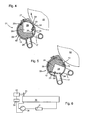
- Fig. 1 shows a schematic section through a squeegee 01 with an employee to a roller 02 of a printing press doctor 03.
- the ink roller 02 is only partially, to a quarter of its circumference, shown.
- the squeegee 03 is at least over the active axial width of the ink roller 02 extending strip of a flexible plastic or rubber material.
- a longitudinal edge 04 of the doctor 03 is in the in Fig. 1st shown extended position of the squeegee 03 on the surface of the ink roller 02 at.
- An opposite longitudinal edge 06 of the squeegee 03 is in a cylindrical sector-shaped closure element 07, z. B. a holding element 07 clamped.
- the holding element 07 is rotatably received in a cylindrical chamber 08 a trough 09.
- the trough 09 is composed of two opposite end plates 11 and the two end plates 11 connecting jacket 12.
- the jacket 12 has substantially the shape of a cylinder, with an elongated opening 13, for. B. a slot 13 at its top and a bent at one edge of the slot 13 outwardly, elongated tab 14, which serves as a support 14 for the doctor blade 03 when wiping the ink roller 02.
- Both end plates 11 are provided with a bore 16, to each of which a supply line or discharge line 17 is connected for a cleaning liquid.
- the holding element 07 After cleaning the inking roller 02, the holding element 07 is rotated together with the doctor 03 about the longitudinal axis A of the chamber 08 in the position shown in Fig. 2.
- the holding element 07 runs at its two longitudinal ends in a circumferentially closed cylindrical ring 18, which exactly fills the inner cross section of the likewise cylindrical chamber 08.
- an external toothing 19 is formed, which meshes with a pinion 21.
- the pinions 21 at both ends of the trough 09 are driven by a same servo motor, not shown.
- the external teeth 19 are each protected by sealing rings 22 against the infiltration of rinsing liquid and possibly color.
- Fig. 2 shows the doctor device 01 in a configuration in which the holding member 07 is rotated by the doctor 03 with respect to the configuration of Fig. 1 by not quite 180 ° clockwise.
- the doctor 03 in a fully retracted into the chamber 08 position.
- the longitudinal edge 04 of the squeegee 03 presses against the casing 12 of the tray 09, and the squeegee 03 is in itself elastically bent.
- the holding element 07 blocks the slot 13, so that the holding element 07 and the jacket 12 form a tube closed all around.
- cleaning fluid is pumped through the chamber 08 at high speed in this configuration of squeegee device 01. Unlike in the configuration of Fig.
- the retracted doctor blade 03 divides a small area 23 from the cross section of the chamber 08, which does not communicate directly with the holes 16 on the end plates 11 of the trough 09 and in which therefore no significant flow of the Cleaning fluid occurs.
- this is irrelevant to the effectiveness of the doctor blade cleaning, since that side surface of the doctor blade 03, which limits the region 23, is not reached when wiping the paint-cleaning liquid mixture from the ink roller 02 of the mixture and remains clean.
- z. B in which the location of at least the associated with the feed bore 16 in their Face plate 11 is moved so that at least part of its cross section opens onto the region 23.
- FIG. 4 shows a second embodiment of a squeegee device 01 in a representation analogous to FIG. 1.
- the same elements that are present in both embodiments are given the same reference numerals and will not be described again.
- the squeegee device 01 of FIG. 4 is designed for a in the perspective of this figure in a clockwise rotating inking roller 02.
- the squeegee 03 is composed of a rigid squeegee lip 24 made of plastic and a spring 26, for. Example, a leaf spring 26 which extends over the entire width of the ink roller 02 as the squeegee 24.
- the leaf spring 26 is screwed on the one hand to the squeegee lip 24 and on the other hand to a holding element 07, which has the same functions as the holding element 07 of FIG.
- the tab 14 of the embodiment of FIG. 1 is replaced by a bolted to the shell 12 rail 27, which holds the free longitudinal edge 04 of the doctor blade 03 against the ink roller 02.
- the rail 27 may be removed to access the interior of the tub 09 for maintenance and repair.
- Inlet and outlet lines 17 for cleaning fluid are not guided by the end plates 11, but close to the opposite ends by the jacket 12 of the trough 09.
- the squeegee 03 When the squeegee 03 is in the retracted position shown in Fig. 5, it divides the free space of the chamber 08 in two areas 23, 28.
- the feed line 17 is arranged so that it on the Area 23 opens, which is limited by the stripped in this embodiment color bearing side surface of the squeegee 03.
- the discharge line 17 opens on the area 28.
- a cleaning liquid flow pumped through the chamber 08 via the supply and discharge lines 17 not only rinses through the chamber 08 in the longitudinal direction, but also forces the squeegee 03 a little way from the casing 12 into the interior of the chamber 08, so that along the longitudinal edge 04 of the squeegee 03, a narrow gap is formed through which the cleaning liquid passes at high speed from the region 23 into the region 28. In this way, a highly effective cleaning especially of the intended for contact with the ink roller 02 longitudinal edge 04 is achieved.
- Two sealing strips 29 made of rubber are embedded in the body of the support member 07 and rotate with it. They are placed so that they come to rest in the closed configuration shown in FIG. 5 on both sides of the slot 13 and reliably prevent leakage of the cleaning liquid to the inking roller 02.
- the squeegee device 01 also comprises a pump 30 which circulates the cleaning liquid in a closed circuit.
- the pump 30 is coupled to a control circuit 32, which also drives the servomotor 33 for the pivoting movement of the holding element 07 and the squeegee 03.
- the control circuit 32 Coupled to the respective position of the holding element 07, the control circuit 32 regulates the throughput of cleaning liquid to a low value with open and a high, a turbulent Cleaning fluid flow promoting value in the closed position.
- the closed circuit filter 31 are further arranged for intercepting dissolved in the cleaning liquid paint residues, so that the doctor device 01 can be operated for a long time maintenance-free.
Landscapes
- Inking, Control Or Cleaning Of Printing Machines (AREA)
- Coating Apparatus (AREA)
- Beans For Foods Or Fodder (AREA)
- Polarising Elements (AREA)
- Cereal-Derived Products (AREA)
Applications Claiming Priority (2)
| Application Number | Priority Date | Filing Date | Title |
|---|---|---|---|
| DE10321189A DE10321189B4 (de) | 2003-05-08 | 2003-05-08 | Rakelvorrichtung |
| PCT/IB2004/001384 WO2004098891A1 (de) | 2003-05-08 | 2004-05-04 | Rakelvorrichtung |
Publications (2)
| Publication Number | Publication Date |
|---|---|
| EP1620267A1 EP1620267A1 (de) | 2006-02-01 |
| EP1620267B1 true EP1620267B1 (de) | 2006-10-11 |
Family
ID=33426736
Family Applications (1)
| Application Number | Title | Priority Date | Filing Date |
|---|---|---|---|
| EP04731068A Expired - Lifetime EP1620267B1 (de) | 2003-05-08 | 2004-05-04 | Rakelvorrichtung |
Country Status (6)
| Country | Link |
|---|---|
| US (1) | US7392744B2 (enExample) |
| EP (1) | EP1620267B1 (enExample) |
| JP (1) | JP2006525149A (enExample) |
| AT (1) | ATE342166T1 (enExample) |
| DE (2) | DE10321189B4 (enExample) |
| WO (1) | WO2004098891A1 (enExample) |
Families Citing this family (7)
| Publication number | Priority date | Publication date | Assignee | Title |
|---|---|---|---|---|
| US8400539B2 (en) * | 2008-11-12 | 2013-03-19 | Bae Systems Information And Electronic Systems Integration Inc. | High density composite focal plane array |
| DE102009018155A1 (de) * | 2009-04-21 | 2010-11-11 | Technotrans Ag | Waschanlage für Druckmaschine |
| DE102010024011A1 (de) | 2010-06-16 | 2011-12-22 | Technotrans Ag | Traversierende Farbkastenreinigung |
| JP5266379B2 (ja) * | 2011-12-28 | 2013-08-21 | ユニ・チャーム株式会社 | 使い捨ておむつ |
| JP5904970B2 (ja) * | 2013-05-07 | 2016-04-20 | ユニ・チャーム株式会社 | 使い捨ておむつ |
| JP5701364B1 (ja) * | 2013-11-05 | 2015-04-15 | 三菱重工印刷紙工機械株式会社 | フレキソ印刷機のインキ洗浄装置及びインキ洗浄方法 |
| US11298935B2 (en) * | 2020-04-27 | 2022-04-12 | Explorer Pressroom Solutions | Wash-up blade |
Family Cites Families (9)
| Publication number | Priority date | Publication date | Assignee | Title |
|---|---|---|---|---|
| US2022635A (en) * | 1935-02-25 | 1935-11-26 | Goss Printing Press Co Ltd | Printing press |
| US2112459A (en) * | 1935-08-03 | 1938-03-29 | News Syndicate Co Inc | Ink fountain construction for use in printing presses |
| BE665608A (enExample) * | 1964-06-25 | |||
| GB1299263A (en) * | 1970-02-04 | 1972-12-13 | Gestetner Ltd | Printing machine blanket cylinder cleaning device |
| US3974768A (en) * | 1975-03-31 | 1976-08-17 | Molins Machine Company, Inc. | Dual ink circulation and wash-up system for a press |
| JPS5418309A (en) | 1977-07-09 | 1979-02-10 | Toppan Printing Co Ltd | Washer for ink roller |
| US5103732A (en) * | 1991-02-14 | 1992-04-14 | Ward Holding Company, Inc. | Doctor blade head assembly and printing apparatus therewith |
| DE29813146U1 (de) | 1998-07-23 | 1998-10-01 | Heidelberger Druckmaschinen Ag, 69115 Heidelberg | Reinigungsvorrichtung in einer Druckmaschine |
| DE20002333U1 (de) | 2000-02-10 | 2000-04-13 | MAN Roland Druckmaschinen AG, 63075 Offenbach | Reinigungsvorrichtung für eine Rotationsdruckmaschine |
-
2003
- 2003-05-08 DE DE10321189A patent/DE10321189B4/de not_active Expired - Fee Related
-
2004
- 2004-05-04 EP EP04731068A patent/EP1620267B1/de not_active Expired - Lifetime
- 2004-05-04 DE DE502004001742T patent/DE502004001742D1/de not_active Expired - Fee Related
- 2004-05-04 US US10/554,809 patent/US7392744B2/en not_active Expired - Fee Related
- 2004-05-04 JP JP2006506572A patent/JP2006525149A/ja active Pending
- 2004-05-04 WO PCT/IB2004/001384 patent/WO2004098891A1/de not_active Ceased
- 2004-05-04 AT AT04731068T patent/ATE342166T1/de not_active IP Right Cessation
Also Published As
| Publication number | Publication date |
|---|---|
| EP1620267A1 (de) | 2006-02-01 |
| US7392744B2 (en) | 2008-07-01 |
| DE10321189A1 (de) | 2004-12-09 |
| US20060278110A1 (en) | 2006-12-14 |
| ATE342166T1 (de) | 2006-11-15 |
| DE10321189B4 (de) | 2007-04-05 |
| WO2004098891A1 (de) | 2004-11-18 |
| DE502004001742D1 (de) | 2006-11-23 |
| JP2006525149A (ja) | 2006-11-09 |
Similar Documents
| Publication | Publication Date | Title |
|---|---|---|
| DE68903778T2 (de) | Druckvorrichtung. | |
| DE69305510T2 (de) | Kammerrakel für druckeinheit und druckeinheit | |
| DE19548535C2 (de) | Verfahren und Vorrichtung zur Reinigung einer Rakelvorrichtung für ein Spülfarbwerk einer Rotationsdruckmaschine | |
| DE2815388A1 (de) | Vorrichtung zum waschen von zylindern an druckmaschinen, insbesondere offsetdruckmaschinen | |
| DE2621307A1 (de) | Verfahren und vorrichtung zur reinigung eines fluessigkeitsfilters | |
| EP0827767B1 (de) | Vorrichtung zum Entwässern von Schlamm und ähnlichen Substanzen | |
| DE112021005224B4 (de) | Reaktionskessel-reinigungsvorrichtung | |
| DE3419698A1 (de) | Vorrichtung zur mechanischen reinigung von fluessigkeiten | |
| DE2917960A1 (de) | Vorrichtung zum waschen und trocknen von lebensmitteln, insbesondere gemuese und obst | |
| EP4168223A1 (de) | Düse zum ausbringen von beton, mörtel oder dergleichen | |
| EP1620267B1 (de) | Rakelvorrichtung | |
| DE2611262C3 (de) | Vorrichtung zur Zu- und Ableitung von Druckfarbe und einer Waschflüssigkeit zum bzw. vom Farbwerk einer Flexodruckmaschine | |
| EP0087645A2 (de) | Vorrichtung zum Reinigen von Wärmetauscher-Röhren und Verfahren zum Betrieb einer derartigen Vorrichtung | |
| DE10203695B4 (de) | Farbwerk für eine Druckmaschine | |
| DE602004009672T2 (de) | Mischer mit reinigungsvorrichtung | |
| EP0252996B1 (de) | Vorrichtung zur filtration einer fluessigkeit | |
| DE2820249C3 (de) | Vorrichtung zum Auftragen einer Beschichtungsflüssigkeit auf eine sich bewegende Bahn | |
| DE1812151A1 (de) | Gummituchwascheinrichtung fuer Buero-Offset-Maschine | |
| DE19727762C2 (de) | Vorrichtung zum Entwässern von Schlamm und ähnlichen Substanzen | |
| DE3048955A1 (de) | Vakuum-trommelfilter | |
| DE102004039162B4 (de) | Vorrichtung zum Beschichten von Papier- und Kartonbahnen | |
| DE102005008937B4 (de) | Beschichtungseinheit in einer Druckmaschine | |
| CH686893A5 (de) | Rechen fuer Wassereinlaeufe. | |
| EP4223134B1 (de) | Vorrichtung zur herstellung eines fliessfähigen produktes | |
| DE2645854C2 (enExample) |
Legal Events
| Date | Code | Title | Description |
|---|---|---|---|
| PUAI | Public reference made under article 153(3) epc to a published international application that has entered the european phase |
Free format text: ORIGINAL CODE: 0009012 |
|
| 17P | Request for examination filed |
Effective date: 20051025 |
|
| AK | Designated contracting states |
Kind code of ref document: A1 Designated state(s): AT BE BG CH CY CZ DE DK EE ES FI FR GB GR HU IE IT LI LU MC NL PL PT RO SE SI SK TR |
|
| GRAP | Despatch of communication of intention to grant a patent |
Free format text: ORIGINAL CODE: EPIDOSNIGR1 |
|
| DAX | Request for extension of the european patent (deleted) | ||
| GRAS | Grant fee paid |
Free format text: ORIGINAL CODE: EPIDOSNIGR3 |
|
| GRAA | (expected) grant |
Free format text: ORIGINAL CODE: 0009210 |
|
| AK | Designated contracting states |
Kind code of ref document: B1 Designated state(s): AT BE BG CH CY CZ DE DK EE ES FI FR GB GR HU IE IT LI LU MC NL PL PT RO SE SI SK TR |
|
| PG25 | Lapsed in a contracting state [announced via postgrant information from national office to epo] |
Ref country code: IT Free format text: LAPSE BECAUSE OF FAILURE TO SUBMIT A TRANSLATION OF THE DESCRIPTION OR TO PAY THE FEE WITHIN THE PRESCRIBED TIME-LIMIT;WARNING: LAPSES OF ITALIAN PATENTS WITH EFFECTIVE DATE BEFORE 2007 MAY HAVE OCCURRED AT ANY TIME BEFORE 2007. THE CORRECT EFFECTIVE DATE MAY BE DIFFERENT FROM THE ONE RECORDED. Effective date: 20061011 Ref country code: PL Free format text: LAPSE BECAUSE OF FAILURE TO SUBMIT A TRANSLATION OF THE DESCRIPTION OR TO PAY THE FEE WITHIN THE PRESCRIBED TIME-LIMIT Effective date: 20061011 Ref country code: NL Free format text: LAPSE BECAUSE OF FAILURE TO SUBMIT A TRANSLATION OF THE DESCRIPTION OR TO PAY THE FEE WITHIN THE PRESCRIBED TIME-LIMIT Effective date: 20061011 Ref country code: CZ Free format text: LAPSE BECAUSE OF FAILURE TO SUBMIT A TRANSLATION OF THE DESCRIPTION OR TO PAY THE FEE WITHIN THE PRESCRIBED TIME-LIMIT Effective date: 20061011 Ref country code: SK Free format text: LAPSE BECAUSE OF FAILURE TO SUBMIT A TRANSLATION OF THE DESCRIPTION OR TO PAY THE FEE WITHIN THE PRESCRIBED TIME-LIMIT Effective date: 20061011 Ref country code: SI Free format text: LAPSE BECAUSE OF FAILURE TO SUBMIT A TRANSLATION OF THE DESCRIPTION OR TO PAY THE FEE WITHIN THE PRESCRIBED TIME-LIMIT Effective date: 20061011 Ref country code: RO Free format text: LAPSE BECAUSE OF FAILURE TO SUBMIT A TRANSLATION OF THE DESCRIPTION OR TO PAY THE FEE WITHIN THE PRESCRIBED TIME-LIMIT Effective date: 20061011 Ref country code: IE Free format text: LAPSE BECAUSE OF FAILURE TO SUBMIT A TRANSLATION OF THE DESCRIPTION OR TO PAY THE FEE WITHIN THE PRESCRIBED TIME-LIMIT Effective date: 20061011 Ref country code: FI Free format text: LAPSE BECAUSE OF FAILURE TO SUBMIT A TRANSLATION OF THE DESCRIPTION OR TO PAY THE FEE WITHIN THE PRESCRIBED TIME-LIMIT Effective date: 20061011 |
|
| REG | Reference to a national code |
Ref country code: GB Ref legal event code: FG4D Free format text: NOT ENGLISH |
|
| REG | Reference to a national code |
Ref country code: CH Ref legal event code: EP |
|
| REG | Reference to a national code |
Ref country code: IE Ref legal event code: FG4D Free format text: LANGUAGE OF EP DOCUMENT: GERMAN |
|
| REF | Corresponds to: |
Ref document number: 502004001742 Country of ref document: DE Date of ref document: 20061123 Kind code of ref document: P |
|
| PG25 | Lapsed in a contracting state [announced via postgrant information from national office to epo] |
Ref country code: SE Free format text: LAPSE BECAUSE OF FAILURE TO SUBMIT A TRANSLATION OF THE DESCRIPTION OR TO PAY THE FEE WITHIN THE PRESCRIBED TIME-LIMIT Effective date: 20070111 Ref country code: BG Free format text: LAPSE BECAUSE OF FAILURE TO SUBMIT A TRANSLATION OF THE DESCRIPTION OR TO PAY THE FEE WITHIN THE PRESCRIBED TIME-LIMIT Effective date: 20070111 Ref country code: DK Free format text: LAPSE BECAUSE OF FAILURE TO SUBMIT A TRANSLATION OF THE DESCRIPTION OR TO PAY THE FEE WITHIN THE PRESCRIBED TIME-LIMIT Effective date: 20070111 |
|
| PG25 | Lapsed in a contracting state [announced via postgrant information from national office to epo] |
Ref country code: ES Free format text: LAPSE BECAUSE OF FAILURE TO SUBMIT A TRANSLATION OF THE DESCRIPTION OR TO PAY THE FEE WITHIN THE PRESCRIBED TIME-LIMIT Effective date: 20070122 |
|
| PG25 | Lapsed in a contracting state [announced via postgrant information from national office to epo] |
Ref country code: PT Free format text: LAPSE BECAUSE OF FAILURE TO SUBMIT A TRANSLATION OF THE DESCRIPTION OR TO PAY THE FEE WITHIN THE PRESCRIBED TIME-LIMIT Effective date: 20070319 |
|
| NLV1 | Nl: lapsed or annulled due to failure to fulfill the requirements of art. 29p and 29m of the patents act | ||
| GBV | Gb: ep patent (uk) treated as always having been void in accordance with gb section 77(7)/1977 [no translation filed] |
Effective date: 20061011 |
|
| EN | Fr: translation not filed | ||
| REG | Reference to a national code |
Ref country code: IE Ref legal event code: FD4D |
|
| PLBE | No opposition filed within time limit |
Free format text: ORIGINAL CODE: 0009261 |
|
| STAA | Information on the status of an ep patent application or granted ep patent |
Free format text: STATUS: NO OPPOSITION FILED WITHIN TIME LIMIT |
|
| 26N | No opposition filed |
Effective date: 20070712 |
|
| PG25 | Lapsed in a contracting state [announced via postgrant information from national office to epo] |
Ref country code: GB Free format text: LAPSE BECAUSE OF FAILURE TO SUBMIT A TRANSLATION OF THE DESCRIPTION OR TO PAY THE FEE WITHIN THE PRESCRIBED TIME-LIMIT Effective date: 20061011 |
|
| BERE | Be: lapsed |
Owner name: KBA-GIORI S.A. Effective date: 20070531 |
|
| PG25 | Lapsed in a contracting state [announced via postgrant information from national office to epo] |
Ref country code: MC Free format text: LAPSE BECAUSE OF NON-PAYMENT OF DUE FEES Effective date: 20070531 |
|
| PG25 | Lapsed in a contracting state [announced via postgrant information from national office to epo] |
Ref country code: BE Free format text: LAPSE BECAUSE OF NON-PAYMENT OF DUE FEES Effective date: 20070531 |
|
| PG25 | Lapsed in a contracting state [announced via postgrant information from national office to epo] |
Ref country code: FR Free format text: LAPSE BECAUSE OF FAILURE TO SUBMIT A TRANSLATION OF THE DESCRIPTION OR TO PAY THE FEE WITHIN THE PRESCRIBED TIME-LIMIT Effective date: 20070601 Ref country code: GR Free format text: LAPSE BECAUSE OF FAILURE TO SUBMIT A TRANSLATION OF THE DESCRIPTION OR TO PAY THE FEE WITHIN THE PRESCRIBED TIME-LIMIT Effective date: 20070112 |
|
| PG25 | Lapsed in a contracting state [announced via postgrant information from national office to epo] |
Ref country code: AT Free format text: LAPSE BECAUSE OF NON-PAYMENT OF DUE FEES Effective date: 20070504 |
|
| PG25 | Lapsed in a contracting state [announced via postgrant information from national office to epo] |
Ref country code: EE Free format text: LAPSE BECAUSE OF FAILURE TO SUBMIT A TRANSLATION OF THE DESCRIPTION OR TO PAY THE FEE WITHIN THE PRESCRIBED TIME-LIMIT Effective date: 20061011 |
|
| PG25 | Lapsed in a contracting state [announced via postgrant information from national office to epo] |
Ref country code: FR Free format text: LAPSE BECAUSE OF FAILURE TO SUBMIT A TRANSLATION OF THE DESCRIPTION OR TO PAY THE FEE WITHIN THE PRESCRIBED TIME-LIMIT Effective date: 20061011 |
|
| PG25 | Lapsed in a contracting state [announced via postgrant information from national office to epo] |
Ref country code: LU Free format text: LAPSE BECAUSE OF NON-PAYMENT OF DUE FEES Effective date: 20070504 Ref country code: CY Free format text: LAPSE BECAUSE OF FAILURE TO SUBMIT A TRANSLATION OF THE DESCRIPTION OR TO PAY THE FEE WITHIN THE PRESCRIBED TIME-LIMIT Effective date: 20061011 |
|
| PGFP | Annual fee paid to national office [announced via postgrant information from national office to epo] |
Ref country code: DE Payment date: 20090526 Year of fee payment: 6 |
|
| PG25 | Lapsed in a contracting state [announced via postgrant information from national office to epo] |
Ref country code: HU Free format text: LAPSE BECAUSE OF FAILURE TO SUBMIT A TRANSLATION OF THE DESCRIPTION OR TO PAY THE FEE WITHIN THE PRESCRIBED TIME-LIMIT Effective date: 20070412 Ref country code: TR Free format text: LAPSE BECAUSE OF FAILURE TO SUBMIT A TRANSLATION OF THE DESCRIPTION OR TO PAY THE FEE WITHIN THE PRESCRIBED TIME-LIMIT Effective date: 20061011 |
|
| PGFP | Annual fee paid to national office [announced via postgrant information from national office to epo] |
Ref country code: CH Payment date: 20090527 Year of fee payment: 6 |
|
| REG | Reference to a national code |
Ref country code: CH Ref legal event code: PFA Owner name: BA-GIORI S.A. Free format text: KBA-GIORI S.A.#4, RUE DE LA PAIX#1003 LAUSANNE (CH) -TRANSFER TO- KBA-GIORI S.A.#AVENUE DU GREY 55 CASE POSTALE 347#1000 LAUSANNE 22 (CH) |
|
| REG | Reference to a national code |
Ref country code: CH Ref legal event code: PL |
|
| PG25 | Lapsed in a contracting state [announced via postgrant information from national office to epo] |
Ref country code: LI Free format text: LAPSE BECAUSE OF NON-PAYMENT OF DUE FEES Effective date: 20100531 Ref country code: CH Free format text: LAPSE BECAUSE OF NON-PAYMENT OF DUE FEES Effective date: 20100531 |
|
| PG25 | Lapsed in a contracting state [announced via postgrant information from national office to epo] |
Ref country code: DE Free format text: LAPSE BECAUSE OF NON-PAYMENT OF DUE FEES Effective date: 20101201 |