EP1619704A1 - Un bouton poussoir - Google Patents
Un bouton poussoir Download PDFInfo
- Publication number
- EP1619704A1 EP1619704A1 EP05105582A EP05105582A EP1619704A1 EP 1619704 A1 EP1619704 A1 EP 1619704A1 EP 05105582 A EP05105582 A EP 05105582A EP 05105582 A EP05105582 A EP 05105582A EP 1619704 A1 EP1619704 A1 EP 1619704A1
- Authority
- EP
- European Patent Office
- Prior art keywords
- rocker
- button
- actuation
- micro
- film
- Prior art date
- Legal status (The legal status is an assumption and is not a legal conclusion. Google has not performed a legal analysis and makes no representation as to the accuracy of the status listed.)
- Granted
Links
Images

Classifications
-
- H—ELECTRICITY
- H01—ELECTRIC ELEMENTS
- H01H—ELECTRIC SWITCHES; RELAYS; SELECTORS; EMERGENCY PROTECTIVE DEVICES
- H01H23/00—Tumbler or rocker switches, i.e. switches characterised by being operated by rocking an operating member in the form of a rocker button
- H01H23/28—Tumbler or rocker switches, i.e. switches characterised by being operated by rocking an operating member in the form of a rocker button with three operating positions
-
- H—ELECTRICITY
- H01—ELECTRIC ELEMENTS
- H01H—ELECTRIC SWITCHES; RELAYS; SELECTORS; EMERGENCY PROTECTIVE DEVICES
- H01H23/00—Tumbler or rocker switches, i.e. switches characterised by being operated by rocking an operating member in the form of a rocker button
- H01H23/02—Details
- H01H23/12—Movable parts; Contacts mounted thereon
- H01H23/14—Tumblers
- H01H23/143—Tumblers having a generally flat elongated shape
Definitions
- the invention relates to a probe with a flat lower part, a movable relative to the lower part flat rocker and the rocker in a basic position oppressive return device, wherein the lower part has a plurality of actuated by the rocker micro-button for making an electrical contact.
- Buttons are used to make electrical contacts, eg. As for the electrical control of certain functions of various technical devices.
- micro-probes for miniaturization of the probe.
- Microtasters are small and have a small actuator with short switching stroke.
- rockers the micro-buttons are actuated by a rocker, which is to exert a pressure.
- the rocker is flat and movable relative to a flat bottom part of the probe.
- the micro buttons are mounted on a circuit board and switch weak control currents. After actuation, the rocker is pressed by a restoring device in a normal position.
- the switching stroke of a micro probe is low. This gives a micro button when actuated a different shift feel than a conventional button, such.
- the invention has for its object to provide a button with a rocker to be actuated micro-probes, which gives the user the feel of a conventional switch button.
- the button has a flat lower part with a movable relative to the lower part flat rocker and the rocker in a basic position oppressive return device, the lower part has a plurality of actuated by the rocker micro-button.
- the reset device has an elastically bendable foil which covers at least one of the micro-probes.
- the lower part of the probe has support elements on which the film rests and the rocker has first projections for bending the film, so that the film exerted a force on the rocker from the projections on the actuating element of the respective micro-probe transmits.
- the path traveled by the rocker when the foil is bent until the micro-button is actuated is greater than the switching stroke of the actuating element of the micro-probe.
- the user is given a different switching feel when pressing the button than when directly pressing the micro button.
- the resulting longer shift stroke and acting against the actuation direction spring force of the elastic film provide a shift feel that of a conventional button, such.
- B. a light sensor corresponds.
- given by the film a technically simple and structurally inexpensive embodiment of a return device.
- the microtast technology can be used in the conventional electrical installation technology, such. B. at wall switches.
- the push button offers the option of using a microswitch that can be actuated directly, in addition to the micro pushbutton that can be actuated indirectly via the foil.
- the rocker may have at least one third projection which, when the second projection actuates the micro-switch, deforms the film, so that the film exerts a restoring force on the rocker due to its elasticity.
- the film is also used as a return device for the directly actuated micro-probe. An additional reset device is not needed.
- the rocker preferably has at least two types of actuation, in which it is tilted about an axis and in each case actuates different microswitches.
- the button has more than two switching functions, such. B. "on-off".
- the rocker In the first mode, the rocker is tilted about a central axis of the base and can be used as a conventional toggle switch.
- the rocker In the second mode, the rocker is pivoted about a first pivot axis and / or a second pivot axis, the first and second pivot axes extending along opposite edges of the base and both pivot axes being perpendicular to the central axis of the first mode.
- the first type of actuation uses the microswitches actuated via the foil.
- the second type of actuation uses the directly actuated micro-pushbuttons.
- the button taught in the first mode of operation for operating conventional switching functions such.
- the rocker may additionally have a non-tilting actuation, in which it is pressed without significant tilting movements and actuates at least two microswitches.
- the two micro-buttons used in the tilt-free actuation mode can be directly actuated micro-buttons.
- the simultaneous operation of the rocker in the first and in the second actuation prevent or prevent the actuation of the rocker in the first type of actuation in the non-tilting actuation.
- These agents can z.
- Example consist of fourth projections which protrude from a peripheral edge of the lower part and abuts against a peripheral wall of the rocker upon actuation of the same, so that a tilting of the rocker according to another type of actuation is not possible. As a result, a combination of certain types of actuation is mechanically prevented.
- the rocker on the tilt axis of the first actuation type locking elements which are in engagement with counter-elements of the lower part, so that the locking elements define the pivot points of the tilting movements of the rocker about the tilt axis.
- the locking elements may be latching hooks and the counter-elements may be notches, in which engage the latching hook.
- the latching hooks can be provided on the lower part and the notches on the rocker. At least one of the notches may be of such size that the latching hook is displaceable in the notch perpendicular to the lower part, so that the respective opposite latching hook defines the pivot point of the pivoting movement of the second actuation of the rocker.
- the lower part can have four micro-probes arranged in a rectangle, of which exactly two diagonally opposite ones of the foil are covered.
- the film may have a cut-out area associated with two buttons not covered by the film.
- one of the micro-switches not covered by the foil is actuated directly.
- the second type of actuation is a Maubetuschistsart.
- the actuating direction is perpendicular to that of the first type of actuation.
- special special functions can be operated, eg. B. the selection of certain light sources or the adjustment of the angle of the slats of blinds.
- the actuation of the rocker in the non-tilting actuation mode could select a defined initial state.
- the first projections for bending the film are arranged on at least two opposite sides of the respective micro-probe.
- the path traveled by the projections in bending the film is longer than the distance traveled by the actuator of the microprobe by the corresponding pressure of the film on the actuator.
- the support elements of the lower part, on which the film rests, may also be arranged on at least two opposite sides of the respective micro-probe.
- the button on a header for a wall socket may be formed as such an attachment or be connected to such.
- the button as conventional light switch can be used.
- the micro-switches can switch weak control currents.
- relays or amplifiers a direct circuit of mains currents is conceivable.
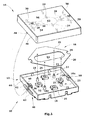
- Fig. 1 shows an exploded view of the button 10 with a lower part 12, a rocker 14 and a film 20 consisting of a return device 16.
- the lower part 12 is formed as a square plate with upstanding edges 44 and corresponds in size to the dimensions of an electrical installation switch.
- the lower part 12 includes a board 33, on which four micro-probes 18 are arranged in a square. Each of the micro-probes 18 has on its upper side an actuating element 26.
- four support elements 22 are arranged in a square on the circuit board 33.
- the support elements 22 are round columns with a base 21 and a tip 23 above the base 21. The diameter of the tip 23 is smaller than the diameter of the base 21st
- the film 20 has a square basic shape with cut corners so that it can be placed diagonally in the lower part 12. It consists of a dimensionally stable hard foil and has an elastic recovery behavior.
- the foil 20 has four circular holes 25 arranged in a square corresponding to the arrangement of the support columns 22, whose diameter is greater than the diameter of the tips 23 and smaller than the diameter of the base 21.
- the film 20 rests on the support elements 22, wherein the tips 23 protrude through the holes 25 of the film 20 and the film 20 is supported by the top of the base 21.
- the film 20 is fixedly positioned by the support elements 22.
- the film 20 may against the lower part 12 and against the Microswitch 18 does not slip.
- the film 20 covers two micro-probes 18, which are based on the square arrangement of the micro-probe 18 at diagonally opposite corners.
- the film has a cut-out region 52 to which the other two micro-buttons 18a are assigned, so that they are not covered by the film 20.
- the rocker 14 consists of a square plate with an upstanding peripheral wall 46.
- the square plate is slightly larger than that of the base 12, and the height of the peripheral edge 44 of the base 12 is slightly less than the height of the peripheral wall 46 of the rocker 14, so that the lower part 12 fits into the rocker 14.
- first protrusions 24 are arranged on opposite sides of the two covered by the film 20 micro-probe.
- second cross-shaped projections 28 are arranged on the underside of the rocker 14 via the actuators 26 of the microtaster 18 not covered by the film 16.
- Third protrusions 30 are arranged between micro button 18 and adjacent peripheral edge 44 of the lower part 12 on the underside of the rocker 14 so that they are at least partially covered by the film 20.
- the means 40 which prevent a combination of certain types of operation, are formed as fourth projections 42 as shown in Fig. 1 at the outer peripheral edge 44 of the lower part 12.
- the projection 42 is a rib arranged centrally on the peripheral edge 44, which is interrupted at the location of the notch 50.
- locking elements 48 are arranged in the form of locking hooks, which are arranged in counter-elements 50 in the form of notches in the outside of the Engage peripheral edge 44 of the lower part 12 and establish a hinged connection between rocker 14 and lower part 12.
- the snap-in hooks 48 latched in the notches 50 define the pivot points of the tilting axis 32 about which the rocker 14 is tilted in the first actuation mode by pressing the rocker 14 within the regions 54 or 56.
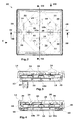
- the function of the button 10 is as follows: The button 10 has three types of actuation. Figures 3 and 4 show sections along the lines III-III and IV-IV in Fig. 2 in the non-actuated state.
- the rocker 14 is in a basic position.
- the film 20 rests on the actuators 26 of the micro-button 18 covered by it.
- the second projections 28 are located above the actuators 26 of the directly actuated micro-stylus 18a.
- the actuating elements 26a are in a basic position and are not pressed.
- the first projections 24 and the third projections 30 for bending the film 20 touch the film, but do not deform it.
- the latching hooks 48 adjoin the upper edge of the notches 50 in the lower part 12.
- Figures 5 and 6 show the button 10 in the actuated state after the first actuation.
- the rocker 14 is tilted about the tilting axis 32 in the arrow direction.
- the right side of the rocker 14 is displaced in the direction of the lower part 12 and over the lower part 12.
- the left side is displaced accordingly in the direction of the lower part 12 away.
- the corresponding projections 24 are pressed against the film 20 by pressing the rocker 14 within the regions 54 or 56.
- the film 20, which is held by the support elements 22 at a distance from the board 33 of the lower part 12, is pressed by the projections 24 in the direction of the board 33 in this distance and against the actuating element 26 of the respective micro-probe 18.
- the film 20 exerts an increasing pressure on the Actuator 26 and pushes when exceeding a certain pressure, the actuator 26 in the micro-probe 18 inside. After relieving the rocker 14, the film 20 returns due to their elastic properties in the initial state. It is supported on the top of the base 21 of the support members 22 and presses against the first projections 24, the rocker back to its normal position.
- FIG. 6 shows the film 16 which has been deformed in the actuated state by the projections 24 via the micro-probe 18 and pushes the actuating element 26 into the micro-probe 18. Due to the lever action of the tilted switch and the deforming foil, the resulting switching stroke for actuating the micro-probe 18 is prolonged.
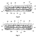
- Figures 7 and 8 show the button 10 in the actuated state of the second actuation.
- the latching hook 48 of the respective opposite peripheral wall 46 is supported on the upper edge of the relevant notches 50.
- the other latching hook 48 slides in the relevant notch 50 in the direction of arrow down.
- the rocker pivots about a first pivot axis 34 in the arrow direction.
- the respective second projection 28 transmits the pressure exerted on the rocker pressure directly on the actuator 26 of the respective micro-probe 18 a and presses this into the micro-probe.
- the corresponding third projection 30 presses against the film 20 and deforms it elastically. After relieving the rocker 14 pushes the film 20 against the actuator 30, the rocker 14 back to its normal position, so that the actuator 26 of the respective micro-probe 18a is relieved again.
- Fig. 9 shows the button 10 in actuated after the non-tilting mode state.
- Both projections 28 press against the actuators 26 of the two not covered by the film 20 micro-probe 18 a.
- Both microswitches 18a are operated directly.
- the two third projections 30 and the first projections 24 press in the direction of arrow against the film 20. After relieving the rocker 14 pushes the film 20 due to their elastic properties against the third projections 30 and against the first projections 24, so that the rocker 14 back in their basic position is being moved.
- the function of the means 40 for preventing a combination of certain types of operation is as follows: Upon actuation of the button 10 in the second mode, the rocker 14 abuts the fourth projections 42 after the actuator 26 of the corresponding micro-button 18a has been pressed by the second projection 28. The lower edge of the peripheral wall 46 abuts against the projection 42 such that tilting of the rocker 14 about the tilting axis 32 according to the first mode of actuation is prevented. Upon actuation of the button 10 in the second mode of actuation in the first mode of actuation is prevented.
Landscapes
- Push-Button Switches (AREA)
- Switches With Compound Operations (AREA)
- Massaging Devices (AREA)
- Acyclic And Carbocyclic Compounds In Medicinal Compositions (AREA)
- Eye Examination Apparatus (AREA)
- Mechanical Control Devices (AREA)
Applications Claiming Priority (1)
| Application Number | Priority Date | Filing Date | Title |
|---|---|---|---|
| DE102004035321A DE102004035321A1 (de) | 2004-07-21 | 2004-07-21 | Taster |
Publications (2)
| Publication Number | Publication Date |
|---|---|
| EP1619704A1 true EP1619704A1 (fr) | 2006-01-25 |
| EP1619704B1 EP1619704B1 (fr) | 2007-08-15 |
Family
ID=34940224
Family Applications (1)
| Application Number | Title | Priority Date | Filing Date |
|---|---|---|---|
| EP05105582A Expired - Lifetime EP1619704B1 (fr) | 2004-07-21 | 2005-06-23 | Un bouton poussoir |
Country Status (4)
| Country | Link |
|---|---|
| EP (1) | EP1619704B1 (fr) |
| AT (1) | ATE370508T1 (fr) |
| DE (2) | DE102004035321A1 (fr) |
| ES (1) | ES2292063T3 (fr) |
Cited By (4)
| Publication number | Priority date | Publication date | Assignee | Title |
|---|---|---|---|---|
| EP2081296A3 (fr) * | 2008-01-18 | 2015-03-25 | Merten GmbH & Co. KG | Interrupteur d'installation électrique |
| US9859886B2 (en) | 2015-08-27 | 2018-01-02 | Fraunhofer-Gesellschaft Zur Foerderung Der Angewandte Forschung E.V. | Switch device and use of the switch device |
| WO2018219748A1 (fr) * | 2017-06-02 | 2018-12-06 | Legrand France | Dispositif de commande |
| EP4009344A1 (fr) * | 2020-12-01 | 2022-06-08 | Simon, S.A.U. | Multi-commutateur |
Families Citing this family (7)
| Publication number | Priority date | Publication date | Assignee | Title |
|---|---|---|---|---|
| DE102006048546B4 (de) * | 2006-10-13 | 2008-10-09 | Abb Ag | Tastsensoreinheit |
| DE102006056270B4 (de) * | 2006-11-27 | 2010-04-15 | Teetronic Gmbh | Manuell betätigbarer elektrischer Wippschalter |
| DE102008014662A1 (de) | 2007-03-17 | 2008-12-18 | Aizo Ag | Verfahren zum Bedienen und Programmieren von Schaltern, insbesondere Lichtschaltern |
| DE202007004163U1 (de) * | 2007-03-17 | 2008-07-31 | Beck, Wilfried | Mehrwegeschalter für Verbraucher in einem Gebäudestromnetz |
| DE102009035545B4 (de) * | 2009-07-31 | 2011-07-28 | Robert Seuffer GmbH & Co. KG, 75365 | Elekrischer Mehrfachschalter |
| EP2911300B1 (fr) | 2014-02-21 | 2021-05-12 | Berker GmbH & Co. KG | Dispositif de commande électrique tactile à retour haptique |
| DE102016104271A1 (de) * | 2016-03-09 | 2017-09-14 | Schneider Electric Industries Sas | Installationsgerät |
Citations (4)
| Publication number | Priority date | Publication date | Assignee | Title |
|---|---|---|---|---|
| US4386254A (en) * | 1981-06-15 | 1983-05-31 | Timex Corporation | Rocker switch |
| US4710602A (en) * | 1986-02-03 | 1987-12-01 | General Motors Corporation | Illuminated rocker switch assembly |
| US20030038020A1 (en) * | 2001-08-24 | 2003-02-27 | Ryoichi Taniuchi | Switch |
| DE10233331C1 (de) * | 2002-07-23 | 2003-11-20 | Berker Gmbh & Co Kg | Elektrisches Schaltgerät |
Family Cites Families (6)
| Publication number | Priority date | Publication date | Assignee | Title |
|---|---|---|---|---|
| DE19844335C1 (de) * | 1998-09-28 | 1999-09-30 | Kostal Leopold Gmbh & Co Kg | Elektrischer Schalter |
| US6225579B1 (en) * | 1999-08-13 | 2001-05-01 | Thomson Licensing S.A. | Multiple switch assembly including gimbal mounted multifunction for selectively operating multiple switches |
| EP1182678B1 (fr) * | 2000-08-23 | 2004-11-10 | Thomson Licensing S.A. | Interrupteur pour l'actionnement de plusieurs éléments de commutation |
| JP2002260493A (ja) * | 2001-03-06 | 2002-09-13 | Alps Electric Co Ltd | 4方向スイッチ装置 |
| DE10117596C1 (de) * | 2001-04-07 | 2002-11-28 | Itt Mfg Enterprises Inc | Wipp- und/oder Tastschalter |
| DE10118172A1 (de) * | 2001-04-11 | 2003-02-06 | Methode Electronics Inc | Bedienschalter für ein Kraftfahrzeug mit einem schwenkbaren Bedienorgan |
-
2004
- 2004-07-21 DE DE102004035321A patent/DE102004035321A1/de not_active Withdrawn
-
2005
- 2005-06-23 AT AT05105582T patent/ATE370508T1/de active
- 2005-06-23 ES ES05105582T patent/ES2292063T3/es not_active Expired - Lifetime
- 2005-06-23 DE DE502005001221T patent/DE502005001221D1/de not_active Expired - Lifetime
- 2005-06-23 EP EP05105582A patent/EP1619704B1/fr not_active Expired - Lifetime
Patent Citations (4)
| Publication number | Priority date | Publication date | Assignee | Title |
|---|---|---|---|---|
| US4386254A (en) * | 1981-06-15 | 1983-05-31 | Timex Corporation | Rocker switch |
| US4710602A (en) * | 1986-02-03 | 1987-12-01 | General Motors Corporation | Illuminated rocker switch assembly |
| US20030038020A1 (en) * | 2001-08-24 | 2003-02-27 | Ryoichi Taniuchi | Switch |
| DE10233331C1 (de) * | 2002-07-23 | 2003-11-20 | Berker Gmbh & Co Kg | Elektrisches Schaltgerät |
Cited By (7)
| Publication number | Priority date | Publication date | Assignee | Title |
|---|---|---|---|---|
| EP2081296A3 (fr) * | 2008-01-18 | 2015-03-25 | Merten GmbH & Co. KG | Interrupteur d'installation électrique |
| US9859886B2 (en) | 2015-08-27 | 2018-01-02 | Fraunhofer-Gesellschaft Zur Foerderung Der Angewandte Forschung E.V. | Switch device and use of the switch device |
| WO2018219748A1 (fr) * | 2017-06-02 | 2018-12-06 | Legrand France | Dispositif de commande |
| FR3067166A1 (fr) * | 2017-06-02 | 2018-12-07 | Legrand France | Dispositif de commande |
| CN110709955A (zh) * | 2017-06-02 | 2020-01-17 | 勒格朗法国公司 | 控制设备 |
| RU2753093C2 (ru) * | 2017-06-02 | 2021-08-11 | Легран Франс | Устройство управления |
| EP4009344A1 (fr) * | 2020-12-01 | 2022-06-08 | Simon, S.A.U. | Multi-commutateur |
Also Published As
| Publication number | Publication date |
|---|---|
| DE102004035321A1 (de) | 2006-02-16 |
| ATE370508T1 (de) | 2007-09-15 |
| DE502005001221D1 (de) | 2007-09-27 |
| ES2292063T3 (es) | 2008-03-01 |
| EP1619704B1 (fr) | 2007-08-15 |
Similar Documents
| Publication | Publication Date | Title |
|---|---|---|
| DE2706463C2 (de) | Druckknopfschalter für elektrische Rechnengeräte wie Tischrechner | |
| DE19924012B4 (de) | In mehreren Richtungen wirksame Eingabevorrichtung | |
| DE19517538C2 (de) | Mehrweg-Kippschalter | |
| DE19537296C2 (de) | Wippenschaltvorrichtung für zweistufigen Betätigungshub | |
| DE19632853C2 (de) | Tastatur mit Tastenschaltern mit Pantograph-Mechanik | |
| DE10324295B4 (de) | Elektrischer Schalter | |
| DE19734997C2 (de) | Druckknopf-Schalter mit scherenartigen Armelementen | |
| DE3103768A1 (de) | Tastschalteranordnung mit mindestens einem tastschalter, insbesondere tastatur | |
| EP1619704B1 (fr) | Un bouton poussoir | |
| DE3328612A1 (de) | Mehrrichtungsschalter | |
| DE102007014778A1 (de) | Elektrischer Schalter mit mehrfachen Schaltpfaden | |
| DE69504602T2 (de) | Tastschalter | |
| DE60101520T2 (de) | Tastschalter mit Tastenkopf welcher auf- und abbewegbar ist und Verfahren zu seiner Herstellung | |
| DE2918640A1 (de) | Druckknopfschalter | |
| DE60006606T2 (de) | Schaltgerät mit Kippbetätigung | |
| EP1537589B1 (fr) | Commutateur a touche de commande a bascule | |
| DE3928650C2 (fr) | ||
| EP3939062B1 (fr) | Dispositif d'installation électrique | |
| EP1912106B1 (fr) | Elément de commande multifonctionnel | |
| DE3618131A1 (de) | Tastschaltervorrichtung | |
| DE19714651A1 (de) | Monostabiles Schaltgerät | |
| DE19836793C2 (de) | Bedienelement zum selektiven Herstellen elektrischer Kontakte | |
| EP0817446A2 (fr) | Dispositif de commutation pour postes téléphoniques | |
| DE202006001717U1 (de) | Elektrischer Schalter mit mehreren Schaltrichtungen | |
| DE3538847A1 (de) | Schalterblock |
Legal Events
| Date | Code | Title | Description |
|---|---|---|---|
| PUAI | Public reference made under article 153(3) epc to a published international application that has entered the european phase |
Free format text: ORIGINAL CODE: 0009012 |
|
| AK | Designated contracting states |
Kind code of ref document: A1 Designated state(s): AT BE BG CH CY CZ DE DK EE ES FI FR GB GR HU IE IS IT LI LT LU MC NL PL PT RO SE SI SK TR |
|
| AX | Request for extension of the european patent |
Extension state: AL BA HR LV MK YU |
|
| 17P | Request for examination filed |
Effective date: 20060110 |
|
| AKX | Designation fees paid |
Designated state(s): AT BE BG CH CY CZ DE DK EE ES FI FR GB GR HU IE IS IT LI LT LU MC NL PL PT RO SE SI SK TR |
|
| GRAP | Despatch of communication of intention to grant a patent |
Free format text: ORIGINAL CODE: EPIDOSNIGR1 |
|
| RIN1 | Information on inventor provided before grant (corrected) |
Inventor name: GOERLICH, WOLFGANG |
|
| GRAS | Grant fee paid |
Free format text: ORIGINAL CODE: EPIDOSNIGR3 |
|
| GRAA | (expected) grant |
Free format text: ORIGINAL CODE: 0009210 |
|
| AK | Designated contracting states |
Kind code of ref document: B1 Designated state(s): AT BE BG CH CY CZ DE DK EE ES FI FR GB GR HU IE IS IT LI LT LU MC NL PL PT RO SE SI SK TR |
|
| REG | Reference to a national code |
Ref country code: GB Ref legal event code: FG4D Free format text: NOT ENGLISH |
|
| REG | Reference to a national code |
Ref country code: CH Ref legal event code: EP |
|
| REG | Reference to a national code |
Ref country code: CH Ref legal event code: NV Representative=s name: ISLER & PEDRAZZINI AG |
|
| REG | Reference to a national code |
Ref country code: IE Ref legal event code: FG4D Free format text: LANGUAGE OF EP DOCUMENT: GERMAN |
|
| REF | Corresponds to: |
Ref document number: 502005001221 Country of ref document: DE Date of ref document: 20070927 Kind code of ref document: P |
|
| REG | Reference to a national code |
Ref country code: CH Ref legal event code: PCAR Free format text: ISLER & PEDRAZZINI AG;POSTFACH 1772;8027 ZUERICH (CH) |
|
| REG | Reference to a national code |
Ref country code: SE Ref legal event code: TRGR |
|
| PG25 | Lapsed in a contracting state [announced via postgrant information from national office to epo] |
Ref country code: FI Free format text: LAPSE BECAUSE OF FAILURE TO SUBMIT A TRANSLATION OF THE DESCRIPTION OR TO PAY THE FEE WITHIN THE PRESCRIBED TIME-LIMIT Effective date: 20070815 Ref country code: BG Free format text: LAPSE BECAUSE OF FAILURE TO SUBMIT A TRANSLATION OF THE DESCRIPTION OR TO PAY THE FEE WITHIN THE PRESCRIBED TIME-LIMIT Effective date: 20071115 Ref country code: LT Free format text: LAPSE BECAUSE OF FAILURE TO SUBMIT A TRANSLATION OF THE DESCRIPTION OR TO PAY THE FEE WITHIN THE PRESCRIBED TIME-LIMIT Effective date: 20070815 Ref country code: IS Free format text: LAPSE BECAUSE OF FAILURE TO SUBMIT A TRANSLATION OF THE DESCRIPTION OR TO PAY THE FEE WITHIN THE PRESCRIBED TIME-LIMIT Effective date: 20071215 |
|
| PG25 | Lapsed in a contracting state [announced via postgrant information from national office to epo] |
Ref country code: PL Free format text: LAPSE BECAUSE OF FAILURE TO SUBMIT A TRANSLATION OF THE DESCRIPTION OR TO PAY THE FEE WITHIN THE PRESCRIBED TIME-LIMIT Effective date: 20070815 |
|
| REG | Reference to a national code |
Ref country code: ES Ref legal event code: FG2A Ref document number: 2292063 Country of ref document: ES Kind code of ref document: T3 |
|
| GBV | Gb: ep patent (uk) treated as always having been void in accordance with gb section 77(7)/1977 [no translation filed] |
Effective date: 20070815 |
|
| ET | Fr: translation filed | ||
| REG | Reference to a national code |
Ref country code: IE Ref legal event code: FD4D |
|
| PG25 | Lapsed in a contracting state [announced via postgrant information from national office to epo] |
Ref country code: GR Free format text: LAPSE BECAUSE OF FAILURE TO SUBMIT A TRANSLATION OF THE DESCRIPTION OR TO PAY THE FEE WITHIN THE PRESCRIBED TIME-LIMIT Effective date: 20071116 Ref country code: DK Free format text: LAPSE BECAUSE OF FAILURE TO SUBMIT A TRANSLATION OF THE DESCRIPTION OR TO PAY THE FEE WITHIN THE PRESCRIBED TIME-LIMIT Effective date: 20070815 |
|
| PG25 | Lapsed in a contracting state [announced via postgrant information from national office to epo] |
Ref country code: SK Free format text: LAPSE BECAUSE OF FAILURE TO SUBMIT A TRANSLATION OF THE DESCRIPTION OR TO PAY THE FEE WITHIN THE PRESCRIBED TIME-LIMIT Effective date: 20070815 Ref country code: IE Free format text: LAPSE BECAUSE OF FAILURE TO SUBMIT A TRANSLATION OF THE DESCRIPTION OR TO PAY THE FEE WITHIN THE PRESCRIBED TIME-LIMIT Effective date: 20070815 Ref country code: PT Free format text: LAPSE BECAUSE OF FAILURE TO SUBMIT A TRANSLATION OF THE DESCRIPTION OR TO PAY THE FEE WITHIN THE PRESCRIBED TIME-LIMIT Effective date: 20080115 Ref country code: GB Free format text: LAPSE BECAUSE OF FAILURE TO SUBMIT A TRANSLATION OF THE DESCRIPTION OR TO PAY THE FEE WITHIN THE PRESCRIBED TIME-LIMIT Effective date: 20070815 Ref country code: CZ Free format text: LAPSE BECAUSE OF FAILURE TO SUBMIT A TRANSLATION OF THE DESCRIPTION OR TO PAY THE FEE WITHIN THE PRESCRIBED TIME-LIMIT Effective date: 20070815 |
|
| PLBE | No opposition filed within time limit |
Free format text: ORIGINAL CODE: 0009261 |
|
| STAA | Information on the status of an ep patent application or granted ep patent |
Free format text: STATUS: NO OPPOSITION FILED WITHIN TIME LIMIT |
|
| PG25 | Lapsed in a contracting state [announced via postgrant information from national office to epo] |
Ref country code: RO Free format text: LAPSE BECAUSE OF FAILURE TO SUBMIT A TRANSLATION OF THE DESCRIPTION OR TO PAY THE FEE WITHIN THE PRESCRIBED TIME-LIMIT Effective date: 20070815 |
|
| 26N | No opposition filed |
Effective date: 20080516 |
|
| PG25 | Lapsed in a contracting state [announced via postgrant information from national office to epo] |
Ref country code: MC Free format text: LAPSE BECAUSE OF NON-PAYMENT OF DUE FEES Effective date: 20080630 |
|
| PG25 | Lapsed in a contracting state [announced via postgrant information from national office to epo] |
Ref country code: EE Free format text: LAPSE BECAUSE OF FAILURE TO SUBMIT A TRANSLATION OF THE DESCRIPTION OR TO PAY THE FEE WITHIN THE PRESCRIBED TIME-LIMIT Effective date: 20070815 |
|
| PG25 | Lapsed in a contracting state [announced via postgrant information from national office to epo] |
Ref country code: SI Free format text: LAPSE BECAUSE OF FAILURE TO SUBMIT A TRANSLATION OF THE DESCRIPTION OR TO PAY THE FEE WITHIN THE PRESCRIBED TIME-LIMIT Effective date: 20070815 |
|
| PG25 | Lapsed in a contracting state [announced via postgrant information from national office to epo] |
Ref country code: CY Free format text: LAPSE BECAUSE OF FAILURE TO SUBMIT A TRANSLATION OF THE DESCRIPTION OR TO PAY THE FEE WITHIN THE PRESCRIBED TIME-LIMIT Effective date: 20070815 |
|
| PG25 | Lapsed in a contracting state [announced via postgrant information from national office to epo] |
Ref country code: HU Free format text: LAPSE BECAUSE OF FAILURE TO SUBMIT A TRANSLATION OF THE DESCRIPTION OR TO PAY THE FEE WITHIN THE PRESCRIBED TIME-LIMIT Effective date: 20080216 Ref country code: LU Free format text: LAPSE BECAUSE OF NON-PAYMENT OF DUE FEES Effective date: 20080623 |
|
| PG25 | Lapsed in a contracting state [announced via postgrant information from national office to epo] |
Ref country code: TR Free format text: LAPSE BECAUSE OF FAILURE TO SUBMIT A TRANSLATION OF THE DESCRIPTION OR TO PAY THE FEE WITHIN THE PRESCRIBED TIME-LIMIT Effective date: 20070815 |
|
| PGFP | Annual fee paid to national office [announced via postgrant information from national office to epo] |
Ref country code: BE Payment date: 20150612 Year of fee payment: 11 |
|
| PGFP | Annual fee paid to national office [announced via postgrant information from national office to epo] |
Ref country code: IT Payment date: 20150625 Year of fee payment: 11 |
|
| REG | Reference to a national code |
Ref country code: FR Ref legal event code: PLFP Year of fee payment: 12 |
|
| PG25 | Lapsed in a contracting state [announced via postgrant information from national office to epo] |
Ref country code: BE Free format text: LAPSE BECAUSE OF NON-PAYMENT OF DUE FEES Effective date: 20160630 |
|
| REG | Reference to a national code |
Ref country code: FR Ref legal event code: PLFP Year of fee payment: 13 |
|
| PG25 | Lapsed in a contracting state [announced via postgrant information from national office to epo] |
Ref country code: IT Free format text: LAPSE BECAUSE OF NON-PAYMENT OF DUE FEES Effective date: 20160623 |
|
| REG | Reference to a national code |
Ref country code: FR Ref legal event code: PLFP Year of fee payment: 14 |
|
| PGFP | Annual fee paid to national office [announced via postgrant information from national office to epo] |
Ref country code: NL Payment date: 20230515 Year of fee payment: 19 Ref country code: FR Payment date: 20230510 Year of fee payment: 19 Ref country code: DE Payment date: 20230502 Year of fee payment: 19 |
|
| PGFP | Annual fee paid to national office [announced via postgrant information from national office to epo] |
Ref country code: SE Payment date: 20230510 Year of fee payment: 19 Ref country code: AT Payment date: 20230525 Year of fee payment: 19 |
|
| PGFP | Annual fee paid to national office [announced via postgrant information from national office to epo] |
Ref country code: ES Payment date: 20230711 Year of fee payment: 19 Ref country code: CH Payment date: 20230702 Year of fee payment: 19 |
|
| REG | Reference to a national code |
Ref country code: DE Ref legal event code: R119 Ref document number: 502005001221 Country of ref document: DE |
|
| REG | Reference to a national code |
Ref country code: SE Ref legal event code: EUG |
|
| REG | Reference to a national code |
Ref country code: CH Ref legal event code: PL |
|
| REG | Reference to a national code |
Ref country code: NL Ref legal event code: MM Effective date: 20240701 |
|
| REG | Reference to a national code |
Ref country code: AT Ref legal event code: MM01 Ref document number: 370508 Country of ref document: AT Kind code of ref document: T Effective date: 20240623 |
|
| PG25 | Lapsed in a contracting state [announced via postgrant information from national office to epo] |
Ref country code: NL Free format text: LAPSE BECAUSE OF NON-PAYMENT OF DUE FEES Effective date: 20240701 |
|
| PG25 | Lapsed in a contracting state [announced via postgrant information from national office to epo] |
Ref country code: NL Free format text: LAPSE BECAUSE OF NON-PAYMENT OF DUE FEES Effective date: 20240701 |
|
| PG25 | Lapsed in a contracting state [announced via postgrant information from national office to epo] |
Ref country code: DE Free format text: LAPSE BECAUSE OF NON-PAYMENT OF DUE FEES Effective date: 20250101 |
|
| PG25 | Lapsed in a contracting state [announced via postgrant information from national office to epo] |
Ref country code: AT Free format text: LAPSE BECAUSE OF NON-PAYMENT OF DUE FEES Effective date: 20240623 Ref country code: CH Free format text: LAPSE BECAUSE OF NON-PAYMENT OF DUE FEES Effective date: 20240630 |
|
| PG25 | Lapsed in a contracting state [announced via postgrant information from national office to epo] |
Ref country code: FR Free format text: LAPSE BECAUSE OF NON-PAYMENT OF DUE FEES Effective date: 20240630 |
|
| REG | Reference to a national code |
Ref country code: ES Ref legal event code: FD2A Effective date: 20250801 |
|
| PG25 | Lapsed in a contracting state [announced via postgrant information from national office to epo] |
Ref country code: ES Free format text: LAPSE BECAUSE OF NON-PAYMENT OF DUE FEES Effective date: 20240624 |
|
| PG25 | Lapsed in a contracting state [announced via postgrant information from national office to epo] |
Ref country code: SE Free format text: LAPSE BECAUSE OF NON-PAYMENT OF DUE FEES Effective date: 20240624 |