EP1618368B1 - Control means for heat load in x-ray scanning apparatus - Google Patents
Control means for heat load in x-ray scanning apparatus Download PDFInfo
- Publication number
- EP1618368B1 EP1618368B1 EP04729148A EP04729148A EP1618368B1 EP 1618368 B1 EP1618368 B1 EP 1618368B1 EP 04729148 A EP04729148 A EP 04729148A EP 04729148 A EP04729148 A EP 04729148A EP 1618368 B1 EP1618368 B1 EP 1618368B1
- Authority
- EP
- European Patent Office
- Prior art keywords
- source
- active
- emission period
- positions
- source positions
- Prior art date
- Legal status (The legal status is an assumption and is not a legal conclusion. Google has not performed a legal analysis and makes no representation as to the accuracy of the status listed.)
- Expired - Lifetime
Links
Images
Classifications
-
- A—HUMAN NECESSITIES
- A61—MEDICAL OR VETERINARY SCIENCE; HYGIENE
- A61B—DIAGNOSIS; SURGERY; IDENTIFICATION
- A61B6/00—Apparatus or devices for radiation diagnosis; Apparatus or devices for radiation diagnosis combined with radiation therapy equipment
- A61B6/02—Arrangements for diagnosis sequentially in different planes; Stereoscopic radiation diagnosis
- A61B6/03—Computed tomography [CT]
- A61B6/032—Transmission computed tomography [CT]
-
- A—HUMAN NECESSITIES
- A61—MEDICAL OR VETERINARY SCIENCE; HYGIENE
- A61B—DIAGNOSIS; SURGERY; IDENTIFICATION
- A61B6/00—Apparatus or devices for radiation diagnosis; Apparatus or devices for radiation diagnosis combined with radiation therapy equipment
- A61B6/40—Arrangements for generating radiation specially adapted for radiation diagnosis
- A61B6/4007—Arrangements for generating radiation specially adapted for radiation diagnosis characterised by using a plurality of source units
- A61B6/4014—Arrangements for generating radiation specially adapted for radiation diagnosis characterised by using a plurality of source units arranged in multiple source-detector units
-
- G—PHYSICS
- G01—MEASURING; TESTING
- G01N—INVESTIGATING OR ANALYSING MATERIALS BY DETERMINING THEIR CHEMICAL OR PHYSICAL PROPERTIES
- G01N23/00—Investigating or analysing materials by the use of wave or particle radiation, e.g. X-rays or neutrons, not covered by groups G01N3/00 – G01N17/00, G01N21/00 or G01N22/00
- G01N23/02—Investigating or analysing materials by the use of wave or particle radiation, e.g. X-rays or neutrons, not covered by groups G01N3/00 – G01N17/00, G01N21/00 or G01N22/00 by transmitting the radiation through the material
- G01N23/04—Investigating or analysing materials by the use of wave or particle radiation, e.g. X-rays or neutrons, not covered by groups G01N3/00 – G01N17/00, G01N21/00 or G01N22/00 by transmitting the radiation through the material and forming images of the material
- G01N23/046—Investigating or analysing materials by the use of wave or particle radiation, e.g. X-rays or neutrons, not covered by groups G01N3/00 – G01N17/00, G01N21/00 or G01N22/00 by transmitting the radiation through the material and forming images of the material using tomography, e.g. computed tomography [CT]
-
- G—PHYSICS
- G01—MEASURING; TESTING
- G01V—GEOPHYSICS; GRAVITATIONAL MEASUREMENTS; DETECTING MASSES OR OBJECTS; TAGS
- G01V5/00—Prospecting or detecting by the use of ionising radiation, e.g. of natural or induced radioactivity
- G01V5/20—Detecting prohibited goods, e.g. weapons, explosives, hazardous substances, contraband or smuggled objects
- G01V5/22—Active interrogation, i.e. by irradiating objects or goods using external radiation sources, e.g. using gamma rays or cosmic rays
-
- H—ELECTRICITY
- H01—ELECTRIC ELEMENTS
- H01J—ELECTRIC DISCHARGE TUBES OR DISCHARGE LAMPS
- H01J35/00—X-ray tubes
- H01J35/02—Details
- H01J35/04—Electrodes ; Mutual position thereof; Constructional adaptations therefor
-
- H—ELECTRICITY
- H01—ELECTRIC ELEMENTS
- H01J—ELECTRIC DISCHARGE TUBES OR DISCHARGE LAMPS
- H01J35/00—X-ray tubes
- H01J35/02—Details
- H01J35/04—Electrodes ; Mutual position thereof; Constructional adaptations therefor
- H01J35/045—Electrodes for controlling the current of the cathode ray, e.g. control grids
-
- H—ELECTRICITY
- H01—ELECTRIC ELEMENTS
- H01J—ELECTRIC DISCHARGE TUBES OR DISCHARGE LAMPS
- H01J35/00—X-ray tubes
- H01J35/24—Tubes wherein the point of impact of the cathode ray on the anode or anticathode is movable relative to the surface thereof
-
- H—ELECTRICITY
- H05—ELECTRIC TECHNIQUES NOT OTHERWISE PROVIDED FOR
- H05G—X-RAY TECHNIQUE
- H05G1/00—X-ray apparatus involving X-ray tubes; Circuits therefor
- H05G1/08—Electrical details
- H05G1/60—Circuit arrangements for obtaining a series of X-ray photographs or for X-ray cinematography
-
- A—HUMAN NECESSITIES
- A61—MEDICAL OR VETERINARY SCIENCE; HYGIENE
- A61B—DIAGNOSIS; SURGERY; IDENTIFICATION
- A61B6/00—Apparatus or devices for radiation diagnosis; Apparatus or devices for radiation diagnosis combined with radiation therapy equipment
- A61B6/40—Arrangements for generating radiation specially adapted for radiation diagnosis
- A61B6/4021—Arrangements for generating radiation specially adapted for radiation diagnosis involving movement of the focal spot
-
- G—PHYSICS
- G01—MEASURING; TESTING
- G01N—INVESTIGATING OR ANALYSING MATERIALS BY DETERMINING THEIR CHEMICAL OR PHYSICAL PROPERTIES
- G01N2223/00—Investigating materials by wave or particle radiation
- G01N2223/40—Imaging
- G01N2223/419—Imaging computed tomograph
Definitions
- the present invention relates to X-ray scanning in which X-rays are directed through an object from a number of positions around the object and the X-rays transmitted through the object are detected and used to build up an image of the object.
- This type of scanning is referred to as computed tomography (CT) scanning.
- One method of CT scanning involves rotating an X-ray source around the object so that it directs X-rays through the object in different directions.
- Another method for example as disclosed in US4274005 , involves positioning a number of X-ray sources around the object and then operating the sources in turn so that the active source position scans round the object.
- FR 2 328 280 discloses an X-ray scanner having a plurality of electron sources arranged to generate X-rays from a plurality of positions about a body.
- US 4 057 725 discloses an X-ray scanner including a multiplicity of radiators and a multiplicity of detectors spaced around an object which can be switched on successively.
- the present invention provides an X-ray imaging apparatus comprising a plurality of X-ray tubes, each tube providing a plurality of source positions therein, the source positions being spaced around an object location and spaced from each other by a source spacing, a plurality of X-ray sensors arranged to be spaced around the object location so as to detect X-rays emitted from the source positions passing through the object location, characterised by control means arranged to control the order in which the source positions are active in successive emission periods over a scanning cycle, such that the average over the scanning cycle of the smallest displacement between an active source position in one emission period and an active source position in the subsequent period is greater than the source spacing, and such that in each emission period an active source position is in a different tube from an active source position in the previous emission period.
- This increase in average spacing between successively active source positions helps to spread the thermal load in the X-ray source.
- said average smallest displacement is at least twice the source spacing. This can most easily be achieved by ensuring that the control means is arranged such that no active source position in any one emission period is adjacent a source position active in the next emission period.
- the control means may arranged so that in each emission period only one source position is active.
- control means may arrange such that in each emission period a plurality of source positions are active simultaneously. This can reduce the scanning time and increase the scanning rate.
- the control means is preferably arranged such that in each emission period, there is no overlap between the groups of sensors for said plurality of source positions. This ensures that the detected X-rays from each of the simultaneously active sources can be distinguished.
- each emission period Preferably in each emission period at least half of the sensors are arranged to receive X-rays from the active source positions. More preferably in each emission period substantially all of the sensors are arranged to receive X-rays from the active source positions.
- the apparatus comprises a plurality of X-ray tubes each providing a plurality of said source positions.
- control means is preferably arranged such that in each emission period the active source position is in a different tube from the active source position in the previous emission period.
- the order in which the source positions are active is arranged such that in each emission period no active source position is adjacent to a source position active in the previous emission period.
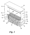
- a multi-focus X-ray tube 10 comprises a ceramic former 12 and an emitter element 18 extending along between the sides 14, 16 of the former.
- a number of grid elements in the form of grid wires 20 are supported on the former 12 and extend over the gap between its two sides 14, 16 perpendicular to the emitter element 18, but in a plane which is parallel to it.
- a number of focusing elements in the form of focusing wires 22 are supported in another plane on the opposite side of the grid wires to the emitter element.
- the focusing wires 22 are parallel to the grid wires 20 and spaced apart from each other with the same spacing as the grid wires, each focusing wire 22 being aligned with a respective one of the grid wires 20.
- the source 10 is enclosed in a housing 24 of an emitter unit 25 with the former 12 being supported on the base 24a of the housing.
- the focusing wires 22 are supported on two support rails 26a, 26b which extend parallel to the emitter element 18, and are spaced from the former 12, the support rails being mounted on the base 24a of the housing.
- the support rails 26a, 26b are electrically conducting so that all of the focusing wires 22 are electrically connected together.
- One of the support rails 26a is connected to a connector 28 which projects through the base 24a of the housing to provide an electrical connection for the focusing wires 22.
- Each of the grid wires 20 extends down one side 16 of the former and is connected to a respective electrical connector 30 which provide separate electrical connections for each of the grid wires 20.
- An anode 32 is supported between the side walls 24b, 24c of the housing.
- the anode extends parallel to the emitter element 18.
- the grid and focusing wires 20, 22 therefore extend between the emitter element 18 and the anode 32.
- An electrical connector 34 to the anode extends through the side wall 24b of the housing.
- the emitter element 18 is supported in the ends of the former and is heated by means of an electric current supplied to it via further connectors 36, 38 in the housing.
- a pair of adj acent grid wires 20 can be connected to an extracting potential which is positive with respect to the element 18 while the remaining grid wires are connected to a blocking potential which is negative with respect to the element 18.
- the position of the beam of electrons can be chosen.
- the position of the X-ray source can also be chosen by choosing the extracting pair of grid wires.
- the focusing elements 22 are all kept at a positive potential with respect to the grid wires 20 so that electrons extracted between any pair of the grid wires will also pass between, and be focussed by, a corresponding pair of focusing elements 22.
- an X-ray scanner 50 is set up in a conventional geometry and comprises an array of emitter units 25 arranged in an arc around a central scanner axis X, and orientated so as to emit X-rays towards the scanner axis X.
- a ring of sensors 52 is placed inside the emitters, directed inwards towards the scanner axis.
- the sensors 52 and emitter units 25 are offset from each other along the axis X so that X-rays emitted from the emitter units pass by the sensors nearest to them, through the object, and are detected by a number of sensors furthest from them.
- the number of sensors 52 that will detect X-rays from each source depends on the width of the fan of X-rays that is emitted from each source position in the tubes 25.
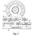
- the scanner is controlled by a control system which operates a number of functions represented buy functional blocks in Figure 5.
- a system control block 54 controls , and receives data/ from, an image display unit 56, an X-ray tube control block 58 and an image reconstruction block 65.
- the X-ray tube control block 58 controls a focus control block 66 which controls the potentials of the focus wires 22 in each of the emitter units 25, a grid control block 67 which controls the potential of the individual grid wires 20 in each emitter unit 25, and a high voltage supply 68 which provides the power to the anode 32 of each of the emitter blocks and the power to the emitter elements 18.
- the image reconstruction block 65 controls and receives data from a sensor control block 70 which in turn controls and receives data from the sensors 52.
- an object to be scanned is passed along the axis X, and X-ray beams are directed through the object from the X-ray tubes 25.
- each source position in each tube 25 is used once, the canning cycle being repeated as the object moves along the axis X.
- Each source position produces a fan of X-rays which after passing through the object are detected by a number of the sensors 52.
- the order in which the tubes and the positions within the tubes are used is controlled as will now be described.
- the order of X-ray emission from the source positions in the tubes 25 is chosen so as to minimize the thermal load on the X-ray tube. This is achieved by ordering the emissions so that each source position is non-adjacent to, and therefore spaced from, the previous one and the subsequent one. This ordering applies both to the source positions within each tube 25, and also to the tubes themselves. Therefore each source position is in a different tube to the previous one and the next one. In fact the best distribution of thermal load is achieved if the source position cycles through all of the tubes, using one position from each tube, and then cycles through the tubes again using a different source position within each tube. The cycling is then repeated until all of the source positions in all of the tubes have been used once. This completes one scanning cycle which can then be repeated.
- each tube the source positions are taken in an order which spreads the thermal load within the tube. This is achieved by ordering the source positions so that the distance between each source position and the next one in that tube, and the previous one in that tube, are both maximized. Firstly, therefore, if the number of source positions per tube allows it, each source position in the tube should be non-adjacent to the next and previous ones in that tube. Then, depending on the number of source positions, the ordering is chosen so as to distribute the thermal load as much as possible.
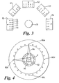
- X-ray tubes 60, 61, 62, 63, 64 numbered in the order in which they are positioned 1, 2, 3, 4 and 5, and each one can produce X-rays from 5 source positions 70, 71, 72, 73, also numbered in order along the tube 60 as 1, 2, 3, 4 and 5, then best ordering for the source positions within each tube is 1, 3, 5, 2, 4.
- the same sequence is also used for ordering the tubes so as to maximize the angular separation between successive emissions.
- a plurality of X-ray sources 80 are spaced around an axis X, with a plurality of sensors 82 axially offset from the sources 80 as in the first embodiment.
- the sources 80a emits an X-ray beam 84 this diverges, passes through the object 86 and reaches a number of the sensors 82.
- the number of sensors 82 which will detect X-rays from each of the sources depends on the width of the beam of X-rays, which is a known quantity for any give system, and can be quantified in terms of a half-angle. This is the angle between the centre of the beam and the edge of the beam.
- source positions can be selected which can emit simultaneously, provided that they do not require any common detectors. For example if there are 24 source positions 80 and 24 sensors 82 and each source position requires 5 sensors, then four of the sensors 80a, 80b, 80c, 80d, spaced around the object at 90° intervals can be used simultaneously.
- the ordering of the emission positions can be varied in a large number of ways for any given number of emission positions, and that the optimum ordering will also vary depending on the number of emission positions and the number of X-ray tubes.
Landscapes
- Health & Medical Sciences (AREA)
- Life Sciences & Earth Sciences (AREA)
- Engineering & Computer Science (AREA)
- Physics & Mathematics (AREA)
- Medical Informatics (AREA)
- Radiology & Medical Imaging (AREA)
- General Health & Medical Sciences (AREA)
- Nuclear Medicine, Radiotherapy & Molecular Imaging (AREA)
- Pathology (AREA)
- High Energy & Nuclear Physics (AREA)
- Optics & Photonics (AREA)
- Heart & Thoracic Surgery (AREA)
- Molecular Biology (AREA)
- Surgery (AREA)
- Animal Behavior & Ethology (AREA)
- Biophysics (AREA)
- Public Health (AREA)
- Veterinary Medicine (AREA)
- Biomedical Technology (AREA)
- General Physics & Mathematics (AREA)
- Pulmonology (AREA)
- Theoretical Computer Science (AREA)
- Chemical & Material Sciences (AREA)
- Biochemistry (AREA)
- Analytical Chemistry (AREA)
- Immunology (AREA)
- General Life Sciences & Earth Sciences (AREA)
- Geophysics (AREA)
- Apparatus For Radiation Diagnosis (AREA)
- X-Ray Techniques (AREA)
- Analysing Materials By The Use Of Radiation (AREA)
- Control Of High-Frequency Heating Circuits (AREA)
- Heating, Cooling, Or Curing Plastics Or The Like In General (AREA)
- Control Of Temperature (AREA)
Applications Claiming Priority (2)
| Application Number | Priority Date | Filing Date | Title |
|---|---|---|---|
| GBGB0309387.9A GB0309387D0 (en) | 2003-04-25 | 2003-04-25 | X-Ray scanning |
| PCT/GB2004/001729 WO2004097386A1 (en) | 2003-04-25 | 2004-04-23 | Control means for heat load in x-ray scanning apparatus |
Publications (2)
| Publication Number | Publication Date |
|---|---|
| EP1618368A1 EP1618368A1 (en) | 2006-01-25 |
| EP1618368B1 true EP1618368B1 (en) | 2009-09-16 |
Family
ID=9957207
Family Applications (1)
| Application Number | Title | Priority Date | Filing Date |
|---|---|---|---|
| EP04729148A Expired - Lifetime EP1618368B1 (en) | 2003-04-25 | 2004-04-23 | Control means for heat load in x-ray scanning apparatus |
Country Status (9)
| Country | Link |
|---|---|
| US (2) | US7564939B2 (enExample) |
| EP (1) | EP1618368B1 (enExample) |
| JP (1) | JP4861818B2 (enExample) |
| CN (1) | CN1781018B (enExample) |
| AT (1) | ATE443253T1 (enExample) |
| DE (1) | DE602004023188D1 (enExample) |
| ES (1) | ES2333331T3 (enExample) |
| GB (2) | GB0309387D0 (enExample) |
| WO (1) | WO2004097386A1 (enExample) |
Cited By (3)
| Publication number | Priority date | Publication date | Assignee | Title |
|---|---|---|---|---|
| WO2019042587A2 (de) | 2017-09-02 | 2019-03-07 | Cetteen Gmbh | Ansteuervorrichtung für eine röntgenröhre und verfahren zum betrieb einer röntgenröhre |
| US10901112B2 (en) | 2003-04-25 | 2021-01-26 | Rapiscan Systems, Inc. | X-ray scanning system with stationary x-ray sources |
| US10976271B2 (en) | 2005-12-16 | 2021-04-13 | Rapiscan Systems, Inc. | Stationary tomographic X-ray imaging systems for automatically sorting objects based on generated tomographic images |
Families Citing this family (50)
| Publication number | Priority date | Publication date | Assignee | Title |
|---|---|---|---|---|
| US7963695B2 (en) | 2002-07-23 | 2011-06-21 | Rapiscan Systems, Inc. | Rotatable boom cargo scanning system |
| US8275091B2 (en) | 2002-07-23 | 2012-09-25 | Rapiscan Systems, Inc. | Compact mobile cargo scanning system |
| US9208988B2 (en) | 2005-10-25 | 2015-12-08 | Rapiscan Systems, Inc. | Graphite backscattered electron shield for use in an X-ray tube |
| US8837669B2 (en) | 2003-04-25 | 2014-09-16 | Rapiscan Systems, Inc. | X-ray scanning system |
| US7949101B2 (en) | 2005-12-16 | 2011-05-24 | Rapiscan Systems, Inc. | X-ray scanners and X-ray sources therefor |
| US8804899B2 (en) | 2003-04-25 | 2014-08-12 | Rapiscan Systems, Inc. | Imaging, data acquisition, data transmission, and data distribution methods and systems for high data rate tomographic X-ray scanners |
| US8094784B2 (en) | 2003-04-25 | 2012-01-10 | Rapiscan Systems, Inc. | X-ray sources |
| US8223919B2 (en) | 2003-04-25 | 2012-07-17 | Rapiscan Systems, Inc. | X-ray tomographic inspection systems for the identification of specific target items |
| GB0309371D0 (en) | 2003-04-25 | 2003-06-04 | Cxr Ltd | X-Ray tubes |
| GB0812864D0 (en) | 2008-07-15 | 2008-08-20 | Cxr Ltd | Coolign anode |
| US9113839B2 (en) | 2003-04-25 | 2015-08-25 | Rapiscon Systems, Inc. | X-ray inspection system and method |
| US8451974B2 (en) | 2003-04-25 | 2013-05-28 | Rapiscan Systems, Inc. | X-ray tomographic inspection system for the identification of specific target items |
| US10483077B2 (en) | 2003-04-25 | 2019-11-19 | Rapiscan Systems, Inc. | X-ray sources having reduced electron scattering |
| US6928141B2 (en) | 2003-06-20 | 2005-08-09 | Rapiscan, Inc. | Relocatable X-ray imaging system and method for inspecting commercial vehicles and cargo containers |
| US7471764B2 (en) | 2005-04-15 | 2008-12-30 | Rapiscan Security Products, Inc. | X-ray imaging system having improved weather resistance |
| US9046465B2 (en) * | 2011-02-24 | 2015-06-02 | Rapiscan Systems, Inc. | Optimization of the source firing pattern for X-ray scanning systems |
| US7706499B2 (en) * | 2006-08-30 | 2010-04-27 | General Electric Company | Acquisition and reconstruction of projection data using a stationary CT geometry |
| DE102007012362A1 (de) * | 2007-03-14 | 2008-09-18 | Siemens Ag | Röntgengerät |
| DE102008004473A1 (de) * | 2008-01-15 | 2009-07-23 | Siemens Aktiengesellschaft | Verfahren und Vorrichtung zur Erzeugung eines tomosynthetischen 3D-Röntgenbildes |
| GB0803644D0 (en) | 2008-02-28 | 2008-04-02 | Rapiscan Security Products Inc | Scanning systems |
| GB0803641D0 (en) | 2008-02-28 | 2008-04-02 | Rapiscan Security Products Inc | Scanning systems |
| GB0809110D0 (en) | 2008-05-20 | 2008-06-25 | Rapiscan Security Products Inc | Gantry scanner systems |
| US7809101B2 (en) | 2008-06-06 | 2010-10-05 | General Electric Company | Modular multispot X-ray source and method of making same |
| GB0816823D0 (en) | 2008-09-13 | 2008-10-22 | Cxr Ltd | X-ray tubes |
| GB0901338D0 (en) | 2009-01-28 | 2009-03-11 | Cxr Ltd | X-Ray tube electron sources |
| US7756249B1 (en) * | 2009-02-19 | 2010-07-13 | Morpho Detection, Inc. | Compact multi-focus x-ray source, x-ray diffraction imaging system, and method for fabricating compact multi-focus x-ray source |
| GB2503358B (en) | 2009-05-26 | 2014-02-12 | Rapiscan Systems Inc | X-ray tomographic inspection systems for the identification of specific target items |
| JP5885661B2 (ja) | 2009-05-26 | 2016-03-15 | ラピスカン システムズ、インコーポレイテッド | 特定の対象物品の識別のためのx線断層撮影検査システム |
| US8713131B2 (en) | 2010-02-23 | 2014-04-29 | RHPiscan Systems, Inc. | Simultaneous image distribution and archiving |
| US9218933B2 (en) | 2011-06-09 | 2015-12-22 | Rapidscan Systems, Inc. | Low-dose radiographic imaging system |
| WO2013008685A1 (ja) * | 2011-07-12 | 2013-01-17 | 富士フイルム株式会社 | 放射線出力装置、放射線撮影システム及び放射線撮影方法 |
| US8948338B2 (en) * | 2011-11-03 | 2015-02-03 | Medtronic Navigation, Inc. | Dynamically scanned X-ray detector panel |
| CN103308535B (zh) * | 2012-03-09 | 2016-04-13 | 同方威视技术股份有限公司 | 用于射线扫描成像的设备和方法 |
| JP6122489B2 (ja) * | 2012-06-05 | 2017-04-26 | ラピスカン システムズ、インコーポレイテッド | X線画像装置 |
| KR102167245B1 (ko) | 2013-01-31 | 2020-10-19 | 라피스캔 시스템스, 인코포레이티드 | 이동식 보안검사시스템 |
| CN104470178A (zh) | 2013-09-18 | 2015-03-25 | 清华大学 | X射线装置以及具有该x射线装置的ct设备 |
| EP3612096A4 (en) | 2017-04-17 | 2020-12-23 | Rapiscan Systems, Inc. | X-RAY TOMOGRAPHIC INSPECTION SYSTEMS AND METHODS |
| CN109216137B (zh) * | 2017-06-30 | 2024-04-05 | 同方威视技术股份有限公司 | 分布式x射线源及其控制方法 |
| US10585206B2 (en) | 2017-09-06 | 2020-03-10 | Rapiscan Systems, Inc. | Method and system for a multi-view scanner |
| JPWO2019151250A1 (ja) * | 2018-01-31 | 2021-02-18 | ナノックス イメージング リミテッド | X線撮影装置及びトモシンセシス画像の合成方法 |
| JP7184584B2 (ja) * | 2018-09-27 | 2022-12-06 | 富士フイルム株式会社 | 放射線撮影装置 |
| US11594001B2 (en) | 2020-01-20 | 2023-02-28 | Rapiscan Systems, Inc. | Methods and systems for generating three-dimensional images that enable improved visualization and interaction with objects in the three-dimensional images |
| JP7479671B2 (ja) * | 2020-05-22 | 2024-05-09 | エア・ウォーター・バイオデザイン株式会社 | Ct装置、ctシステムおよびct方法 |
| US11551903B2 (en) | 2020-06-25 | 2023-01-10 | American Science And Engineering, Inc. | Devices and methods for dissipating heat from an anode of an x-ray tube assembly |
| EP3933881A1 (en) | 2020-06-30 | 2022-01-05 | VEC Imaging GmbH & Co. KG | X-ray source with multiple grids |
| CN114795262B (zh) * | 2020-11-27 | 2025-07-11 | 北京纳米维景科技有限公司 | 面向心脏扫描的多源静态ct系统及其成像方法 |
| US12361671B2 (en) | 2021-09-07 | 2025-07-15 | Rapiscan Systems, Inc. | Methods and systems for accurate visual layer separation in the displays of scanning systems |
| US12230468B2 (en) | 2022-06-30 | 2025-02-18 | Varex Imaging Corporation | X-ray system with field emitters and arc protection |
| GB2635043A (en) | 2022-07-26 | 2025-04-30 | Rapiscan Holdings Inc | Methods and systems for performing on-the-fly automatic calibration adjustments of X-ray inspection systems |
| KR102810838B1 (ko) * | 2022-12-20 | 2025-05-22 | 한국원자력의학원 | 냉각 부담이 저감된 x선 조사장치 |
Family Cites Families (83)
| Publication number | Priority date | Publication date | Assignee | Title |
|---|---|---|---|---|
| US32961A (en) * | 1861-07-30 | Animal-trap | ||
| US2952790A (en) * | 1957-07-15 | 1960-09-13 | Raytheon Co | X-ray tubes |
| US3239706A (en) * | 1961-04-17 | 1966-03-08 | High Voltage Engineering Corp | X-ray target |
| US3768645A (en) * | 1971-02-22 | 1973-10-30 | Sunkist Growers Inc | Method and means for automatically detecting and sorting produce according to internal damage |
| GB1497396A (en) | 1974-03-23 | 1978-01-12 | Emi Ltd | Radiography |
| USRE32961E (en) | 1974-09-06 | 1989-06-20 | U.S. Philips Corporation | Device for measuring local radiation absorption in a body |
| DE2442809A1 (de) * | 1974-09-06 | 1976-03-18 | Philips Patentverwaltung | Anordnung zur ermittlung der absorption in einem koerper |
| GB1526041A (en) | 1975-08-29 | 1978-09-27 | Emi Ltd | Sources of x-radiation |
| NL7611391A (nl) * | 1975-10-18 | 1977-04-20 | Emi Ltd | Roentgentoestel. |
| DE2647167C2 (de) * | 1976-10-19 | 1987-01-29 | Siemens AG, 1000 Berlin und 8000 München | Vorrichtung zur Herstellung von Schichtaufnahmen mit Röntgen- oder ähnlich durchdringenden Strahlen |
| DE2705640A1 (de) * | 1977-02-10 | 1978-08-17 | Siemens Ag | Rechnersystem fuer den bildaufbau eines koerperschnittbildes und verfahren zum betrieb des rechnersystems |
| US4105922A (en) * | 1977-04-11 | 1978-08-08 | General Electric Company | CT number identifier in a computed tomography system |
| DE2729353A1 (de) | 1977-06-29 | 1979-01-11 | Siemens Ag | Roentgenroehre mit wanderndem brennfleck |
| DE2807735B2 (de) | 1978-02-23 | 1979-12-20 | Philips Patentverwaltung Gmbh, 2000 Hamburg | Röntgenröhre mit einem aus Metall bestehenden Röhrenkolben |
| US4228353A (en) * | 1978-05-02 | 1980-10-14 | Johnson Steven A | Multiple-phase flowmeter and materials analysis apparatus and method |
| JPS5546408A (en) * | 1978-09-29 | 1980-04-01 | Toshiba Corp | X-ray device |
| US4266425A (en) * | 1979-11-09 | 1981-05-12 | Zikonix Corporation | Method for continuously determining the composition and mass flow of butter and similar substances from a manufacturing process |
| US4352021A (en) * | 1980-01-07 | 1982-09-28 | The Regents Of The University Of California | X-Ray transmission scanning system and method and electron beam X-ray scan tube for use therewith |
| GB2089109B (en) | 1980-12-03 | 1985-05-15 | Machlett Lab Inc | X-rays targets and tubes |
| DE3107949A1 (de) * | 1981-03-02 | 1982-09-16 | Siemens AG, 1000 Berlin und 8000 München | Roentgenroehre |
| FR2534066B1 (fr) * | 1982-10-05 | 1989-09-08 | Thomson Csf | Tube a rayons x produisant un faisceau a haut rendement, notamment en forme de pinceau |
| US4672649A (en) * | 1984-05-29 | 1987-06-09 | Imatron, Inc. | Three dimensional scanned projection radiography using high speed computed tomographic scanning system |
| GB8521287D0 (en) * | 1985-08-27 | 1985-10-02 | Frith B | Flow measurement & imaging |
| US4799247A (en) * | 1986-06-20 | 1989-01-17 | American Science And Engineering, Inc. | X-ray imaging particularly adapted for low Z materials |
| JPS6321040A (ja) * | 1986-07-16 | 1988-01-28 | 工業技術院長 | 超高速x線ctスキヤナ |
| JPS63109653A (ja) * | 1986-10-27 | 1988-05-14 | Sharp Corp | 情報登録検索装置 |
| GB2212903B (en) | 1987-11-24 | 1991-11-06 | Rolls Royce Plc | Measuring two phase flow in pipes. |
| US4887604A (en) * | 1988-05-16 | 1989-12-19 | Science Research Laboratory, Inc. | Apparatus for performing dual energy medical imaging |
| EP0432568A3 (en) | 1989-12-11 | 1991-08-28 | General Electric Company | X ray tube anode and tube having same |
| DE4100297A1 (de) * | 1991-01-08 | 1992-07-09 | Philips Patentverwaltung | Roentgenroehre |
| DE4103588C1 (enExample) * | 1991-02-06 | 1992-05-27 | Siemens Ag, 8000 Muenchen, De | |
| US5272627A (en) * | 1991-03-27 | 1993-12-21 | Gulton Industries, Inc. | Data converter for CT data acquisition system |
| EP0531993B1 (en) | 1991-09-12 | 1998-01-07 | Kabushiki Kaisha Toshiba | X-ray computerized tomographic imaging method and imaging system capable of forming scanogram data from helically scanned data |
| US5367552A (en) * | 1991-10-03 | 1994-11-22 | In Vision Technologies, Inc. | Automatic concealed object detection system having a pre-scan stage |
| US5966422A (en) * | 1992-07-20 | 1999-10-12 | Picker Medical Systems, Ltd. | Multiple source CT scanner |
| DE4228559A1 (de) | 1992-08-27 | 1994-03-03 | Dagang Tan | Röntgenröhre mit einer Transmissionsanode |
| DE4304332A1 (de) * | 1993-02-13 | 1994-08-18 | Philips Patentverwaltung | Verfahren zur Erzeugung von Schichtbildern und Anordnung zur Durchführung des Verfahrens |
| US5511104A (en) * | 1994-03-11 | 1996-04-23 | Siemens Aktiengesellschaft | X-ray tube |
| US5467377A (en) * | 1994-04-15 | 1995-11-14 | Dawson; Ralph L. | Computed tomographic scanner |
| SE9401300L (sv) | 1994-04-18 | 1995-10-19 | Bgc Dev Ab | Roterande cylinderkollimator för kollimering av joniserande, elektromagnetisk strålning |
| DE4436688A1 (de) * | 1994-10-13 | 1996-04-25 | Siemens Ag | Computertomograph |
| AUPN226295A0 (en) * | 1995-04-07 | 1995-05-04 | Technological Resources Pty Limited | A method and an apparatus for analysing a material |
| US6018562A (en) * | 1995-11-13 | 2000-01-25 | The United States Of America As Represented By The Secretary Of The Army | Apparatus and method for automatic recognition of concealed objects using multiple energy computed tomography |
| DE19542438C1 (de) * | 1995-11-14 | 1996-11-28 | Siemens Ag | Röntgenröhre |
| US5633907A (en) * | 1996-03-21 | 1997-05-27 | General Electric Company | X-ray tube electron beam formation and focusing |
| DE19618749A1 (de) * | 1996-05-09 | 1997-11-13 | Siemens Ag | Röntgen-Computertomograph |
| US5974111A (en) * | 1996-09-24 | 1999-10-26 | Vivid Technologies, Inc. | Identifying explosives or other contraband by employing transmitted or scattered X-rays |
| US5859891A (en) * | 1997-03-07 | 1999-01-12 | Hibbard; Lyn | Autosegmentation/autocontouring system and method for use with three-dimensional radiation therapy treatment planning |
| JPH10272128A (ja) * | 1997-03-31 | 1998-10-13 | Futec Inc | 直接断層撮影方法及び装置 |
| US6149592A (en) | 1997-11-26 | 2000-11-21 | Picker International, Inc. | Integrated fluoroscopic projection image data, volumetric image data, and surgical device position data |
| US6005918A (en) | 1997-12-19 | 1999-12-21 | Picker International, Inc. | X-ray tube window heat shield |
| US5987097A (en) * | 1997-12-23 | 1999-11-16 | General Electric Company | X-ray tube having reduced window heating |
| US6218943B1 (en) * | 1998-03-27 | 2001-04-17 | Vivid Technologies, Inc. | Contraband detection and article reclaim system |
| US6236709B1 (en) * | 1998-05-04 | 2001-05-22 | Ensco, Inc. | Continuous high speed tomographic imaging system and method |
| US6097786A (en) | 1998-05-18 | 2000-08-01 | Schlumberger Technology Corporation | Method and apparatus for measuring multiphase flows |
| US6183139B1 (en) * | 1998-10-06 | 2001-02-06 | Cardiac Mariners, Inc. | X-ray scanning method and apparatus |
| US6181765B1 (en) * | 1998-12-10 | 2001-01-30 | General Electric Company | X-ray tube assembly |
| US6546072B1 (en) * | 1999-07-30 | 2003-04-08 | American Science And Engineering, Inc. | Transmission enhanced scatter imaging |
| US6269142B1 (en) * | 1999-08-11 | 2001-07-31 | Steven W. Smith | Interrupted-fan-beam imaging |
| US6528787B2 (en) * | 1999-11-30 | 2003-03-04 | Jeol Ltd. | Scanning electron microscope |
| JP2001176408A (ja) | 1999-12-15 | 2001-06-29 | New Japan Radio Co Ltd | 電子管 |
| US6324247B1 (en) * | 1999-12-30 | 2001-11-27 | Ge Medical Systems Global Technology Company, Llc | Partial scan weighting for multislice CT imaging with arbitrary pitch |
| EP1287388A2 (en) * | 2000-06-07 | 2003-03-05 | American Science & Engineering, Inc. | X-ray scatter and transmission system with coded beams |
| US6876724B2 (en) | 2000-10-06 | 2005-04-05 | The University Of North Carolina - Chapel Hill | Large-area individually addressable multi-beam x-ray system and method of forming same |
| US6735271B1 (en) * | 2000-11-28 | 2004-05-11 | Ge Medical Systems Global Technology Company Llc | Electron beam computed tomographic scanner system with helical or tilted target, collimator, and detector components to eliminate cone beam error and to scan continuously moving objects |
| US6385292B1 (en) * | 2000-12-29 | 2002-05-07 | Ge Medical Systems Global Technology Company, Llc | Solid-state CT system and method |
| JPWO2002067779A1 (ja) | 2001-02-28 | 2004-06-24 | 三菱重工業株式会社 | 多線源型x線ct装置 |
| US6324249B1 (en) * | 2001-03-21 | 2001-11-27 | Agilent Technologies, Inc. | Electronic planar laminography system and method |
| WO2002082372A1 (en) | 2001-04-03 | 2002-10-17 | L-3 Communications Security & Detection Systems | A remote baggage screening system, software and method |
| GB0115615D0 (en) * | 2001-06-27 | 2001-08-15 | Univ Coventry | Image segmentation |
| US6636623B2 (en) * | 2001-08-10 | 2003-10-21 | Visiongate, Inc. | Optical projection imaging system and method for automatically detecting cells with molecular marker compartmentalization associated with malignancy and disease |
| CN1344534A (zh) * | 2001-11-09 | 2002-04-17 | 曹文田 | 一种螺旋计算机断层摄影仪 |
| WO2003051201A2 (en) | 2001-12-14 | 2003-06-26 | Wisconsin Alumni Research Foundation | Virtual spherical anode computed tomography |
| JP2005520661A (ja) * | 2002-03-23 | 2005-07-14 | コーニンクレッカ フィリップス エレクトロニクス エヌ ヴィ | 対象に含まれる構造のインタラクティブなセグメンテーションの方法 |
| US6754300B2 (en) | 2002-06-20 | 2004-06-22 | Ge Medical Systems Global Technology Company, Llc | Methods and apparatus for operating a radiation source |
| JP2004079128A (ja) | 2002-08-22 | 2004-03-11 | Matsushita Electric Ind Co Ltd | 光ディスク記録装置 |
| ATE496291T1 (de) | 2002-10-02 | 2011-02-15 | Reveal Imaging Technologies Inc | Kompakter ct-scanner für gepäckstücke mit detektoranordnungen in unterschiedlichem abstand zur röntgenquelle |
| US6922460B2 (en) * | 2003-06-11 | 2005-07-26 | Quantum Magnetics, Inc. | Explosives detection system using computed tomography (CT) and quadrupole resonance (QR) sensors |
| US7492855B2 (en) | 2003-08-07 | 2009-02-17 | General Electric Company | System and method for detecting an object |
| JP3909048B2 (ja) | 2003-09-05 | 2007-04-25 | ジーイー・メディカル・システムズ・グローバル・テクノロジー・カンパニー・エルエルシー | X線ct装置およびx線管 |
| US7099435B2 (en) * | 2003-11-15 | 2006-08-29 | Agilent Technologies, Inc | Highly constrained tomography for automated inspection of area arrays |
| US7280631B2 (en) | 2003-11-26 | 2007-10-09 | General Electric Company | Stationary computed tomography system and method |
| US7233644B1 (en) * | 2004-11-30 | 2007-06-19 | Ge Homeland Protection, Inc. | Computed tomographic scanner using rastered x-ray tubes |
-
2003
- 2003-04-25 GB GBGB0309387.9A patent/GB0309387D0/en not_active Ceased
-
2004
- 2004-04-23 GB GB0520903A patent/GB2416654B/en not_active Expired - Lifetime
- 2004-04-23 CN CN2004800112124A patent/CN1781018B/zh not_active Expired - Fee Related
- 2004-04-23 US US10/554,656 patent/US7564939B2/en not_active Expired - Lifetime
- 2004-04-23 ES ES04729148T patent/ES2333331T3/es not_active Expired - Lifetime
- 2004-04-23 JP JP2006506163A patent/JP4861818B2/ja not_active Expired - Fee Related
- 2004-04-23 AT AT04729148T patent/ATE443253T1/de not_active IP Right Cessation
- 2004-04-23 EP EP04729148A patent/EP1618368B1/en not_active Expired - Lifetime
- 2004-04-23 WO PCT/GB2004/001729 patent/WO2004097386A1/en not_active Ceased
- 2004-04-23 DE DE602004023188T patent/DE602004023188D1/de not_active Expired - Lifetime
-
2009
- 2009-06-16 US US12/485,897 patent/US20090316855A1/en not_active Abandoned
Cited By (4)
| Publication number | Priority date | Publication date | Assignee | Title |
|---|---|---|---|---|
| US10901112B2 (en) | 2003-04-25 | 2021-01-26 | Rapiscan Systems, Inc. | X-ray scanning system with stationary x-ray sources |
| US11796711B2 (en) | 2003-04-25 | 2023-10-24 | Rapiscan Systems, Inc. | Modular CT scanning system |
| US10976271B2 (en) | 2005-12-16 | 2021-04-13 | Rapiscan Systems, Inc. | Stationary tomographic X-ray imaging systems for automatically sorting objects based on generated tomographic images |
| WO2019042587A2 (de) | 2017-09-02 | 2019-03-07 | Cetteen Gmbh | Ansteuervorrichtung für eine röntgenröhre und verfahren zum betrieb einer röntgenröhre |
Also Published As
| Publication number | Publication date |
|---|---|
| CN1781018A (zh) | 2006-05-31 |
| US20070172023A1 (en) | 2007-07-26 |
| ES2333331T3 (es) | 2010-02-19 |
| GB2416654B (en) | 2006-12-13 |
| US7564939B2 (en) | 2009-07-21 |
| DE602004023188D1 (de) | 2009-10-29 |
| WO2004097386A1 (en) | 2004-11-11 |
| GB0309387D0 (en) | 2003-06-04 |
| ATE443253T1 (de) | 2009-10-15 |
| JP4861818B2 (ja) | 2012-01-25 |
| WO2004097386A8 (en) | 2005-01-20 |
| US20090316855A1 (en) | 2009-12-24 |
| JP2006524809A (ja) | 2006-11-02 |
| GB2416654A (en) | 2006-02-01 |
| GB0520903D0 (en) | 2005-11-23 |
| CN1781018B (zh) | 2011-06-08 |
| EP1618368A1 (en) | 2006-01-25 |
Similar Documents
| Publication | Publication Date | Title |
|---|---|---|
| EP1618368B1 (en) | Control means for heat load in x-ray scanning apparatus | |
| US6385292B1 (en) | Solid-state CT system and method | |
| US7142629B2 (en) | Stationary computed tomography system and method | |
| US8085897B2 (en) | X-ray scanning system | |
| US9046465B2 (en) | Optimization of the source firing pattern for X-ray scanning systems | |
| US20050111610A1 (en) | Stationary computed tomography system and method | |
| CN102473574B (zh) | 具有独立的x和z动态焦斑偏转的X射线管 | |
| EP1371330A1 (en) | X-ray ct apparatus and x-ray ct apparatus imaging method | |
| JP2000175895A (ja) | コンピュ―タ断層撮影及び画像診断法 | |
| CN102422364A (zh) | 具有多个电子发射器的x射线源 | |
| EP2104945A2 (en) | X-ray tube with multiple electron sources and common electron deflection unit | |
| US20050121616A1 (en) | Split scan line and combined data line x-ray detectors | |
| JP2008168039A (ja) | X線発生装置およびx線ct装置 | |
| JPWO2017170408A1 (ja) | X線検出システム、x線装置、並びに、x線検出データを処理する装置及び方法 | |
| JP4585195B2 (ja) | X線ct装置 | |
| CN104486997B (zh) | X射线扫描系统的射线源激发模式的最佳化 | |
| CN102711618B (zh) | 利用组合的x和y焦斑偏转方法的x射线管 | |
| EP1840935B1 (en) | X-ray inspection system with coordination between detector and multiple focal spots | |
| JP5337437B2 (ja) | X線ct装置及びx線ct装置のデータ収集方法 | |
| CN114068267B (zh) | 偏转电极组件、x射线源和x射线成像系统 | |
| JP2010148920A (ja) | X線ct装置 |
Legal Events
| Date | Code | Title | Description |
|---|---|---|---|
| PUAI | Public reference made under article 153(3) epc to a published international application that has entered the european phase |
Free format text: ORIGINAL CODE: 0009012 |
|
| 17P | Request for examination filed |
Effective date: 20051116 |
|
| AK | Designated contracting states |
Kind code of ref document: A1 Designated state(s): AT BE BG CH CY CZ DE DK EE ES FI FR GB GR HU IE IT LI LU MC NL PL PT RO SE SI SK TR |
|
| AX | Request for extension of the european patent |
Extension state: AL HR LT LV MK |
|
| DAX | Request for extension of the european patent (deleted) | ||
| GRAP | Despatch of communication of intention to grant a patent |
Free format text: ORIGINAL CODE: EPIDOSNIGR1 |
|
| GRAS | Grant fee paid |
Free format text: ORIGINAL CODE: EPIDOSNIGR3 |
|
| GRAA | (expected) grant |
Free format text: ORIGINAL CODE: 0009210 |
|
| RAP1 | Party data changed (applicant data changed or rights of an application transferred) |
Owner name: CXR LIMITED |
|
| AK | Designated contracting states |
Kind code of ref document: B1 Designated state(s): AT BE BG CH CY CZ DE DK EE ES FI FR GB GR HU IE IT LI LU MC NL PL PT RO SE SI SK TR |
|
| REG | Reference to a national code |
Ref country code: GB Ref legal event code: FG4D |
|
| REG | Reference to a national code |
Ref country code: CH Ref legal event code: EP |
|
| REG | Reference to a national code |
Ref country code: IE Ref legal event code: FG4D |
|
| REF | Corresponds to: |
Ref document number: 602004023188 Country of ref document: DE Date of ref document: 20091029 Kind code of ref document: P |
|
| PG25 | Lapsed in a contracting state [announced via postgrant information from national office to epo] |
Ref country code: SE Free format text: LAPSE BECAUSE OF FAILURE TO SUBMIT A TRANSLATION OF THE DESCRIPTION OR TO PAY THE FEE WITHIN THE PRESCRIBED TIME-LIMIT Effective date: 20090916 Ref country code: FI Free format text: LAPSE BECAUSE OF FAILURE TO SUBMIT A TRANSLATION OF THE DESCRIPTION OR TO PAY THE FEE WITHIN THE PRESCRIBED TIME-LIMIT Effective date: 20090916 |
|
| REG | Reference to a national code |
Ref country code: CH Ref legal event code: NV Representative=s name: NOVAGRAAF INTERNATIONAL SA |
|
| REG | Reference to a national code |
Ref country code: ES Ref legal event code: FG2A Ref document number: 2333331 Country of ref document: ES Kind code of ref document: T3 |
|
| PG25 | Lapsed in a contracting state [announced via postgrant information from national office to epo] |
Ref country code: PL Free format text: LAPSE BECAUSE OF FAILURE TO SUBMIT A TRANSLATION OF THE DESCRIPTION OR TO PAY THE FEE WITHIN THE PRESCRIBED TIME-LIMIT Effective date: 20090916 Ref country code: SI Free format text: LAPSE BECAUSE OF FAILURE TO SUBMIT A TRANSLATION OF THE DESCRIPTION OR TO PAY THE FEE WITHIN THE PRESCRIBED TIME-LIMIT Effective date: 20090916 Ref country code: NL Free format text: LAPSE BECAUSE OF FAILURE TO SUBMIT A TRANSLATION OF THE DESCRIPTION OR TO PAY THE FEE WITHIN THE PRESCRIBED TIME-LIMIT Effective date: 20090916 |
|
| NLV1 | Nl: lapsed or annulled due to failure to fulfill the requirements of art. 29p and 29m of the patents act | ||
| PG25 | Lapsed in a contracting state [announced via postgrant information from national office to epo] |
Ref country code: CY Free format text: LAPSE BECAUSE OF FAILURE TO SUBMIT A TRANSLATION OF THE DESCRIPTION OR TO PAY THE FEE WITHIN THE PRESCRIBED TIME-LIMIT Effective date: 20090916 |
|
| PG25 | Lapsed in a contracting state [announced via postgrant information from national office to epo] |
Ref country code: PT Free format text: LAPSE BECAUSE OF FAILURE TO SUBMIT A TRANSLATION OF THE DESCRIPTION OR TO PAY THE FEE WITHIN THE PRESCRIBED TIME-LIMIT Effective date: 20100118 Ref country code: RO Free format text: LAPSE BECAUSE OF FAILURE TO SUBMIT A TRANSLATION OF THE DESCRIPTION OR TO PAY THE FEE WITHIN THE PRESCRIBED TIME-LIMIT Effective date: 20090916 Ref country code: CZ Free format text: LAPSE BECAUSE OF FAILURE TO SUBMIT A TRANSLATION OF THE DESCRIPTION OR TO PAY THE FEE WITHIN THE PRESCRIBED TIME-LIMIT Effective date: 20090916 Ref country code: EE Free format text: LAPSE BECAUSE OF FAILURE TO SUBMIT A TRANSLATION OF THE DESCRIPTION OR TO PAY THE FEE WITHIN THE PRESCRIBED TIME-LIMIT Effective date: 20090916 |
|
| PG25 | Lapsed in a contracting state [announced via postgrant information from national office to epo] |
Ref country code: SK Free format text: LAPSE BECAUSE OF FAILURE TO SUBMIT A TRANSLATION OF THE DESCRIPTION OR TO PAY THE FEE WITHIN THE PRESCRIBED TIME-LIMIT Effective date: 20090916 |
|
| PG25 | Lapsed in a contracting state [announced via postgrant information from national office to epo] |
Ref country code: BE Free format text: LAPSE BECAUSE OF FAILURE TO SUBMIT A TRANSLATION OF THE DESCRIPTION OR TO PAY THE FEE WITHIN THE PRESCRIBED TIME-LIMIT Effective date: 20090916 Ref country code: AT Free format text: LAPSE BECAUSE OF FAILURE TO SUBMIT A TRANSLATION OF THE DESCRIPTION OR TO PAY THE FEE WITHIN THE PRESCRIBED TIME-LIMIT Effective date: 20090916 |
|
| PLBE | No opposition filed within time limit |
Free format text: ORIGINAL CODE: 0009261 |
|
| STAA | Information on the status of an ep patent application or granted ep patent |
Free format text: STATUS: NO OPPOSITION FILED WITHIN TIME LIMIT |
|
| PG25 | Lapsed in a contracting state [announced via postgrant information from national office to epo] |
Ref country code: DK Free format text: LAPSE BECAUSE OF FAILURE TO SUBMIT A TRANSLATION OF THE DESCRIPTION OR TO PAY THE FEE WITHIN THE PRESCRIBED TIME-LIMIT Effective date: 20090916 |
|
| 26N | No opposition filed |
Effective date: 20100617 |
|
| PG25 | Lapsed in a contracting state [announced via postgrant information from national office to epo] |
Ref country code: GR Free format text: LAPSE BECAUSE OF FAILURE TO SUBMIT A TRANSLATION OF THE DESCRIPTION OR TO PAY THE FEE WITHIN THE PRESCRIBED TIME-LIMIT Effective date: 20091217 |
|
| PG25 | Lapsed in a contracting state [announced via postgrant information from national office to epo] |
Ref country code: MC Free format text: LAPSE BECAUSE OF NON-PAYMENT OF DUE FEES Effective date: 20100430 |
|
| PGFP | Annual fee paid to national office [announced via postgrant information from national office to epo] |
Ref country code: GB Payment date: 20100618 Year of fee payment: 7 |
|
| PG25 | Lapsed in a contracting state [announced via postgrant information from national office to epo] |
Ref country code: IE Free format text: LAPSE BECAUSE OF NON-PAYMENT OF DUE FEES Effective date: 20100423 |
|
| REG | Reference to a national code |
Ref country code: CH Ref legal event code: PFA Owner name: CXR LIMITED Free format text: CXR LIMITED#SEVEN GABLES HOUSE 30 LETCHMORE ROAD#RADLETT HERTFORDSHIRE WD7 8HT (GB) -TRANSFER TO- CXR LIMITED#SEVEN GABLES HOUSE 30 LETCHMORE ROAD#RADLETT HERTFORDSHIRE WD7 8HT (GB) |
|
| REG | Reference to a national code |
Ref country code: DE Ref legal event code: R409 Ref document number: 602004023188 Country of ref document: DE |
|
| GBPC | Gb: european patent ceased through non-payment of renewal fee |
Effective date: 20110423 |
|
| PG25 | Lapsed in a contracting state [announced via postgrant information from national office to epo] |
Ref country code: DE Free format text: LAPSE BECAUSE OF NON-PAYMENT OF DUE FEES Effective date: 20111101 |
|
| REG | Reference to a national code |
Ref country code: DE Ref legal event code: R119 Ref document number: 602004023188 Country of ref document: DE Effective date: 20111101 |
|
| PG25 | Lapsed in a contracting state [announced via postgrant information from national office to epo] |
Ref country code: GB Free format text: LAPSE BECAUSE OF NON-PAYMENT OF DUE FEES Effective date: 20110423 |
|
| REG | Reference to a national code |
Ref country code: DE Ref legal event code: R409 Ref document number: 602004023188 Country of ref document: DE |
|
| PG25 | Lapsed in a contracting state [announced via postgrant information from national office to epo] |
Ref country code: BG Free format text: LAPSE BECAUSE OF FAILURE TO SUBMIT A TRANSLATION OF THE DESCRIPTION OR TO PAY THE FEE WITHIN THE PRESCRIBED TIME-LIMIT Effective date: 20090916 Ref country code: LU Free format text: LAPSE BECAUSE OF NON-PAYMENT OF DUE FEES Effective date: 20100423 Ref country code: HU Free format text: LAPSE BECAUSE OF FAILURE TO SUBMIT A TRANSLATION OF THE DESCRIPTION OR TO PAY THE FEE WITHIN THE PRESCRIBED TIME-LIMIT Effective date: 20100317 |
|
| PG25 | Lapsed in a contracting state [announced via postgrant information from national office to epo] |
Ref country code: TR Free format text: LAPSE BECAUSE OF FAILURE TO SUBMIT A TRANSLATION OF THE DESCRIPTION OR TO PAY THE FEE WITHIN THE PRESCRIBED TIME-LIMIT Effective date: 20090916 |
|
| PGRI | Patent reinstated in contracting state [announced from national office to epo] |
Ref country code: DE Effective date: 20120713 |
|
| REG | Reference to a national code |
Ref country code: FR Ref legal event code: PLFP Year of fee payment: 13 |
|
| REG | Reference to a national code |
Ref country code: FR Ref legal event code: PLFP Year of fee payment: 14 |
|
| REG | Reference to a national code |
Ref country code: FR Ref legal event code: PLFP Year of fee payment: 15 |
|
| REG | Reference to a national code |
Ref country code: DE Ref legal event code: R082 Ref document number: 602004023188 Country of ref document: DE Representative=s name: SAMSON & PARTNER PATENTANWAELTE MBB, DE Ref country code: DE Ref legal event code: R081 Ref document number: 602004023188 Country of ref document: DE Owner name: CXR LTD., GB Free format text: FORMER OWNER: CXR LTD., RADLETT, HERTFORDSHIRE, GB |
|
| PGFP | Annual fee paid to national office [announced via postgrant information from national office to epo] |
Ref country code: ES Payment date: 20200515 Year of fee payment: 17 Ref country code: CH Payment date: 20200414 Year of fee payment: 17 Ref country code: FR Payment date: 20200410 Year of fee payment: 17 Ref country code: DE Payment date: 20200422 Year of fee payment: 17 |
|
| PGFP | Annual fee paid to national office [announced via postgrant information from national office to epo] |
Ref country code: IT Payment date: 20200407 Year of fee payment: 17 |
|
| REG | Reference to a national code |
Ref country code: DE Ref legal event code: R119 Ref document number: 602004023188 Country of ref document: DE |
|
| PG25 | Lapsed in a contracting state [announced via postgrant information from national office to epo] |
Ref country code: LI Free format text: LAPSE BECAUSE OF NON-PAYMENT OF DUE FEES Effective date: 20210430 Ref country code: CH Free format text: LAPSE BECAUSE OF NON-PAYMENT OF DUE FEES Effective date: 20210430 Ref country code: FR Free format text: LAPSE BECAUSE OF NON-PAYMENT OF DUE FEES Effective date: 20210430 Ref country code: DE Free format text: LAPSE BECAUSE OF NON-PAYMENT OF DUE FEES Effective date: 20211103 |
|
| REG | Reference to a national code |
Ref country code: ES Ref legal event code: FD2A Effective date: 20220701 |
|
| PG25 | Lapsed in a contracting state [announced via postgrant information from national office to epo] |
Ref country code: ES Free format text: LAPSE BECAUSE OF NON-PAYMENT OF DUE FEES Effective date: 20210424 |
|
| PG25 | Lapsed in a contracting state [announced via postgrant information from national office to epo] |
Ref country code: IT Free format text: LAPSE BECAUSE OF NON-PAYMENT OF DUE FEES Effective date: 20200423 |
|
| PG25 | Lapsed in a contracting state [announced via postgrant information from national office to epo] |
Ref country code: IT Free format text: LAPSE BECAUSE OF NON-PAYMENT OF DUE FEES Effective date: 20210423 |