EP1617162A2 - Wärmetauscher - Google Patents
Wärmetauscher Download PDFInfo
- Publication number
- EP1617162A2 EP1617162A2 EP05013991A EP05013991A EP1617162A2 EP 1617162 A2 EP1617162 A2 EP 1617162A2 EP 05013991 A EP05013991 A EP 05013991A EP 05013991 A EP05013991 A EP 05013991A EP 1617162 A2 EP1617162 A2 EP 1617162A2
- Authority
- EP
- European Patent Office
- Prior art keywords
- tube sheet
- tank
- heat exchanger
- tube
- identifiers
- Prior art date
- Legal status (The legal status is an assumption and is not a legal conclusion. Google has not performed a legal analysis and makes no representation as to the accuracy of the status listed.)
- Granted
Links
Images


Classifications
-
- F—MECHANICAL ENGINEERING; LIGHTING; HEATING; WEAPONS; BLASTING
- F28—HEAT EXCHANGE IN GENERAL
- F28D—HEAT-EXCHANGE APPARATUS, NOT PROVIDED FOR IN ANOTHER SUBCLASS, IN WHICH THE HEAT-EXCHANGE MEDIA DO NOT COME INTO DIRECT CONTACT
- F28D1/00—Heat-exchange apparatus having stationary conduit assemblies for one heat-exchange medium only, the media being in contact with different sides of the conduit wall, in which the other heat-exchange medium is a large body of fluid, e.g. domestic or motor car radiators
- F28D1/02—Heat-exchange apparatus having stationary conduit assemblies for one heat-exchange medium only, the media being in contact with different sides of the conduit wall, in which the other heat-exchange medium is a large body of fluid, e.g. domestic or motor car radiators with heat-exchange conduits immersed in the body of fluid
- F28D1/03—Heat-exchange apparatus having stationary conduit assemblies for one heat-exchange medium only, the media being in contact with different sides of the conduit wall, in which the other heat-exchange medium is a large body of fluid, e.g. domestic or motor car radiators with heat-exchange conduits immersed in the body of fluid with plate-like or laminated conduits
- F28D1/0308—Heat-exchange apparatus having stationary conduit assemblies for one heat-exchange medium only, the media being in contact with different sides of the conduit wall, in which the other heat-exchange medium is a large body of fluid, e.g. domestic or motor car radiators with heat-exchange conduits immersed in the body of fluid with plate-like or laminated conduits the conduits being formed by paired plates touching each other
- F28D1/0325—Heat-exchange apparatus having stationary conduit assemblies for one heat-exchange medium only, the media being in contact with different sides of the conduit wall, in which the other heat-exchange medium is a large body of fluid, e.g. domestic or motor car radiators with heat-exchange conduits immersed in the body of fluid with plate-like or laminated conduits the conduits being formed by paired plates touching each other the plates having lateral openings therein for circulation of the heat-exchange medium from one conduit to another
- F28D1/0333—Heat-exchange apparatus having stationary conduit assemblies for one heat-exchange medium only, the media being in contact with different sides of the conduit wall, in which the other heat-exchange medium is a large body of fluid, e.g. domestic or motor car radiators with heat-exchange conduits immersed in the body of fluid with plate-like or laminated conduits the conduits being formed by paired plates touching each other the plates having lateral openings therein for circulation of the heat-exchange medium from one conduit to another the plates having integrated connecting members
-
- F—MECHANICAL ENGINEERING; LIGHTING; HEATING; WEAPONS; BLASTING
- F28—HEAT EXCHANGE IN GENERAL
- F28F—DETAILS OF HEAT-EXCHANGE AND HEAT-TRANSFER APPARATUS, OF GENERAL APPLICATION
- F28F9/00—Casings; Header boxes; Auxiliary supports for elements; Auxiliary members within casings
- F28F9/02—Header boxes; End plates
- F28F9/0202—Header boxes having their inner space divided by partitions
- F28F9/0204—Header boxes having their inner space divided by partitions for elongated header box, e.g. with transversal and longitudinal partitions
- F28F9/0209—Header boxes having their inner space divided by partitions for elongated header box, e.g. with transversal and longitudinal partitions having only transversal partitions
-
- F—MECHANICAL ENGINEERING; LIGHTING; HEATING; WEAPONS; BLASTING
- F28—HEAT EXCHANGE IN GENERAL
- F28F—DETAILS OF HEAT-EXCHANGE AND HEAT-TRANSFER APPARATUS, OF GENERAL APPLICATION
- F28F2280/00—Mounting arrangements; Arrangements for facilitating assembling or disassembling of heat exchanger parts
- F28F2280/04—Means for preventing wrong assembling of parts
Definitions
- the present invention relates to a heat exchanger with a plurality of tube sheets stacked in layers.
- a known heat exchanger has a plurality of flat tubes stacked in layers.
- each flat tube has a coolant passage extending in a longitudinal direction and a cylindrical tank protruding in the stacking direction from each side of each longitudinal end of the coolant passage.
- the tanks of the stacked flat tubes are joined to form a header tank.
- Each flat tube consists of two tube sheets that are arranged face to face and are joined together.
- Each tube sheet has a flat part, a recess part that is depressed from the flat part to form the coolant passage of the flat tube when joined with a counterpart tube sheet, and a cylindrical tank that protrudes from each longitudinal end of the recess part to serve as the tank of the flat tube.
- the heat exchanger must form therein a route for passing a coolant.
- a modified tube sheet is arranged at a predetermined location in the heat exchanger.
- the modified tube sheet has a modified tank that is different from a normal tank provided for a normal tube sheet.
- the modified tank has a partition to close an opening of the tank, or a throttle to reduce the opening of the tank.
- Such a modified tube sheet with a modified tank has the same or similar external shape as the normal tube sheet. It is difficult, therefore, to identify, from an external view of the heat exchanger, the modified tube sheets from among the stacked tube sheets of the heat exchanger. To solve the problem, Japanese Unexamined Patent Application Publication No.
- Hei-9-152294 discloses a heat exchanger that puts a mark such as a rib or a notch on a modified tube sheet. This heat exchanger allows a person to identify, from an external view of the heat exchanger, the modified tube sheet in the heat exchanger.
- an inspector needs to identify, from the exterior of the heat exchanger, the location of a modified tube sheet from among stacked tube sheets in the heat exchanger, as well as the end of the modified tube sheet where a modified tank with a partition or a throttle is present. Such identification of the modified tube sheet is also carried out after the manufacturing of the heat exchanger when installing the heat exchanger in, for example, a vehicle. If the modified tube sheet is not identifiable form the exterior of the heat exchanger, a worker will be unable to correctly install the heat exchanger in the vehicle.
- the modified tube sheet may be provided with a mark such as a notch or a rib at the end of the modified tube sheet where the partition or throttle is present.
- This configuration may allow a person to identify the location of the partition or throttle only if the person checks each side of the heat exchanger. Namely, this configuration forces the person to turn over the heat exchanger to inspect each side of the heat exchanger. This is troublesome for the person.
- the present invention provides a heat exchanger that allows a person to understand an internal structure (the locations of partitions and throttles) of the heat exchanger by inspecting only one side of the heat exchanger from the exterior of the heat exchanger.
- a first aspect of the present invention provides a heat exchanger having a plurality of flat tubes stacked in layers.
- Each of the plurality of flat tubes has a pair of tube sheets facing each other and joined together.
- the tube sheets have a flat part, a depressed recess part having end portions and extending in a longitudinal direction, and a cylindrical tank protruding from the end portions of the recess part.
- the tube sheet is one of either a first tube sheet or a second tube sheet.
- the first tube sheet has a first type of tank positioned at each end thereof.
- the second tube sheet has a first type of tank at one end portion of the recess part and a second type of tank at the other end portion of the recess part.
- Identifiers are provided at each end of the second tube sheet. The identifiers distinguish the second tube sheet from the first tube sheet when viewed from externally of the stacked flat tubes. A mark is provided at one of the identifiers of the second tube sheet.
- a second aspect of the present invention provides a heat exchanger having a plurality of flat tubes stacked in layers.
- Each of the plurality of flat tubes has a pair of tube sheets facing each other and joined together.
- the tube sheets have a flat part, a depressed recess part having end portions and extending in a longitudinal direction, and a cylindrical tank protruding from the end portions of the recess part.
- the tube sheet is one of either a first tube sheet or a second tube sheet.
- the first tube sheet has a first type of tank positioned at each end thereof.
- the second tube sheet has a first type of tank at one end portion of the recess part and a second type of tank at the other end portion of the recess part. Identifiers are provided at each end of the second tube sheet.
- the identifiers distinguish the second tube sheet from the first tube sheet when viewed from externally of the stacked flat tubes.
- a first mark is provided at one of the identifiers of the second tube sheet.
- a second mark is provided at the other of the identifiers of the second tube sheet.
- FIGs 1A to 1D show a heat exchanger 10 according to a first embodiment of the present invention.
- the heat exchanger 10 has a plurality of flat tubes 11 stacked in layers with fins 12 interposed between the layers of the flat tubes 11.
- a flat tube 11 has a coolant passage 13 (Figs. 2 and 3) formed in the flat tube 11 and extending in a longitudinal direction (vertical direction in Fig. 1A) and a cylindrical tank 22 protruding from each longitudinal end portion of the coolant passage 13 in the stacking direction (horizontal direction in Fig. 1A).
- the flat tubes 11 are stacked in layers and the tanks 22 of the adjacent tubes 11 are connected to each other to communicate with each other.
- the connected tanks 22 form a header tank 14 extending in the stacking direction (horizontal direction in Fig. 1A).
- the header tanks 14 merge and distribute a coolant through the coolant passages 13.
- each flat tube 11 has two separate coolant passages 13 as shown in Figs. 2 and 3. Accordingly, the flat tube 11 has two tanks 22 at each end. Namely, there are two header tanks 14 at the top end of the heat exchanger 10 and two header tanks 14 at the bottom end thereof as shown in Fig. 1A.
- An end plate 15 is arranged at a right end (as shown in the drawing) of the heat exchanger 10.
- a passage 16 is formed in the end plate 15, to connect the top and bottom header tanks 14 to each other.
- An end plate 17 is formed at a left end (as shown in the drawing) of the heat exchanger 10.
- a connector 100 is fixed to the end plate 17 and is connected to the left ends of the top header tanks 14.
- a coolant inlet 101 is formed on the connector 100 to communicate with one of the top header tanks 14.
- a coolant outlet 102 is formed on the connector 100 to communicate with the other top header tank 14.
- Tube sheets that form the flat tube 11 will be explained with reference to Figs. 4A and 4B.
- a flat tube 11 is formed by arranging two metal tube sheets 1A face to face and by joining the two sheets together.
- the first embodiment employs a first tube sheet 1A shown in Fig. 4A and a second tube sheet 1B shown in Fig. 4B.
- the first tube sheet 1A has a flat part 20, a recess part 21 that is depressed from the flat part 20 and to form the coolant passage 13 of the flat tube 11, and a cylindrical tank 22 protruding from each longitudinal end portion of the recess part 21, in a thickness direction, to form the tank 22 of the flat tube 11.
- the tank of the tube sheet is represented with the same reference numeral "22" as that used for the tank of the flat tube 11.
- the tube sheet 1A has two recess parts 21 and four tanks 22, to form the flat tube 11.
- the four tanks 22 of the tube sheet 1A are first tanks 22A, each having a communication opening.
- the second tube sheet 1B has substantially the same shape as the first tube sheet 1A. Namely, the second tube sheet 1B has a flat part 20, two coolant passing recess parts 21, and four cylindrical tanks 22. Among the four cylindrical tanks 22 of the second tube sheet 1B, one is a second type of tank 22B that is closed and the other three are the first type tanks 22A, each having a communication opening.
- the second tube sheet 1B is arranged at a predetermined location in the stacked flat tubes 11, to form a partition (with the second tank 22B of the second tube sheet 1B) in the header tank 14 of the heat exchanger 10.
- This structure defines a coolant passing route in the heat exchanger 10.
- Opposite ends of the second tube sheet 1B have projections (as identifiers) 31 and 32, respectively.
- the projections 31 and 32 allow a person to easily understand, from an external inspection of the heat exchanger 10, the location of the second tube sheet 1B in the heat exchanger 10.
- the projections 31 and 32 have different shapes. According to the first embodiment, the projection 31 is at the end of the second tube sheet 1B where the closed second tank 22B is present.
- the projection 31 is not provided with a notch (as a mark) M.
- the projection 32 at the opposite end of the second tube sheet 1B is provided with the notch M.
- the projections 31 and 32 are formed close to one of the two coolant passing recess parts 21 that are provided with the second tank 22B.
- the partition (second tank 22B) is present in the vicinity of the non-notched projection 31, or that the partition (second tank 22B) is present on the opposite end of the notched projection 32.
- the projections 31 and 32 may be bent as shown in Fig. 6 if required.
- FIGS 7A to 7C, 8A, and 8B show a heat exchanger according to a second embodiment of the present invention.
- the first embodiment employs one type of second tanks.
- the second embodiment employs two types of second tanks.
- the two types of second tanks are formed on different tube sheets.
- plurality types of second tanks may be formed on the same tube sheet.
- the heat exchanger 10C employs three tube sheets, a first tube sheet 1A shown in Fig. 7A, a second tube sheet 1B shown in Fig. 7B, and a modified second tube sheet 1C shown in Fig. 7C.
- the first tube sheet 1A and second tube sheet 1B are the same as those of the first embodiment.
- the modified second tube sheet 1C has four tanks 22, among which one is a second tank 22C having a throttle and the remaining three are first tanks 22A.
- ends of the modified second tube sheet 1C have projections (as identifiers) 41 and 42, respectively.
- the projections 41 and 42 are used to distinguish the modified second tube sheet 1C from the first tube sheet 1A.
- the projections 41 and 42 must also be distinguishable from the projections (as identifiers) 31 and 32 of the second tube sheet 1B.
- the projections 41 and 42 are differed in size from the projections 31 and 32.
- the projection 41 is formed at the end of the second tube sheet 1C where the modified second tank 22C is present.
- the projection 41 is not provided with a mark M, to thereby serve as a first mark.
- the projection 42 at the opposite end has the mark M.
- the projections 41 and 42 are formed close to one of the two coolant passing recess parts 21 that are provided with the second tank 22C.
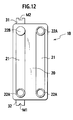
- Figures 8A and 8B show the heat exchanger 10C with the tube sheets of Figs. 7A to 7C stacked in layers, in which Fig. 8A is a top view and Fig. 8B is a bottom view.
- the heat exchanger 10C includes the first tube sheets 1A and the second and modified second tube sheets 1B and 1C.
- the second and modified second tube sheets 1B and 1C are oriented in predetermined directions.
- a header tank 14 of the heat exchanger 10C is partitioned with the second tank 22B, to define a coolant route in the heat exchanger 10C.
- the modified second tank 22C forms a throttle in the coolant route.
- a mark P indicates the location of the partition formed with the second tank 22B
- a mark Q indicates the location of the throttle formed with the modified second tank 22C.
- At least one of the shape, size, and position of the identifiers is differed from type to type to identify the types of second tanks. Examples of this will be explained with reference to Figs. 9A to 11C.
- Figures 9A to 9C show projections 51A to 51C and 52A to 52C having different shapes (for example, square, triangle, and semicircle) to specify the types of second tanks (second tube sheets).
- Each projection is provided with or without a mark M to indicate whether the second tank is present at the end where the projection is formed or at the opposite end.
- Figures 10A to 10C show projections 61A to 61C and 62A to 62C having different sizes (LA, LB, and LC) to specify the types of second tanks (second tube sheets). Each projection is provided with or without a mark M to indicate whether the second tank is present at the end where the projection is formed or at the opposite end.
- Figures 11A to 11C show projections 71A to 71C and 72A to 72C formed at different positions (distances LA, LB, and LC from an edge) to specify the types of second tanks (second tube sheets). Each projection is provided with or without a mark M to indicate whether the second tank is present at the end where the projection is formed or at the opposite end.
- the identifiers may be changed in various ways to distinguish different types of second tanks from one another and to identify an end where the second tank is present.
- At least one of the shape, size, and position of identifiers assigned to the types of second tanks may be differed from type to type.
- any other one of the shape, size, and position of identifiers may be differed between opposite ends of each second tube sheet to identify an end where a second tank is present. This technique may eliminate the use of a mark on the identifiers.
- the mark on an identifier is a notch.
- the present invention may use any other mark.
- the mark may be a through hole, a recess, a projection, or the like.
- the mark is provided at the end of the second tube sheet where the second tank is absent.
- the mark may be provided at the end of the second tube sheet where the second tank is present.
- the identifier extends from each longitudinal end of a second tube sheet in a longitudinal direction.
- the identifier may be arranged at any position in the vicinity of each longitudinal end of a second tube sheet.
- the identifier may extend from a longitudinal end of a second tube sheet in a direction orthogonal to the longitudinal direction.
- the mark is provided on one of the identifiers.
- the marks M1 and M2 may be provided at each end of the second tube sheet 1B.
- a first mark M1 is provided at the end where the second tank 22B is absent.
- a second mark M2, different from the first mark M1, is provided at the end where the second tank 22B is present.
- the identifiers at each end of the second tube sheet may have different shapes, sizes, or positions, to serve for the first and second marks that are distinguishable from each other.
- the first and second embodiments make the identifiers easily distinguishable from each other and avoid a mistake of identifying identifiers.
- the identifiers for identifying the types of second tanks are differed in the shape, size, or position thereof from type to type.
- identifiers arranged at the ends thereof are differed from each other in the shape, size, or position other than that used for identifying the types of second tanks, so that the identifiers on each second tube sheet may serve for the first and second marks, respectively.
- the identifiers are differed in the shape thereof from type to type to identify the types of second tube sheets, and on each second tube sheet, the identifiers are differed in the size or position thereof to serve as the first and second marks, respectively, (II) the identifiers are differed in the size thereof from type to type to identify the types of second tube sheets, and on each second tube sheet, the identifiers are differed in the shape or position thereof to serve as the first and second marks, respectively, or (III) the identifiers are differed in the position thereof from type to type to identify the types of second tube sheets, and on each second tube sheet, the identifiers are differed in the shape or size thereof to serve as the first and second marks, respectively.
Landscapes
- Engineering & Computer Science (AREA)
- Physics & Mathematics (AREA)
- Thermal Sciences (AREA)
- Mechanical Engineering (AREA)
- General Engineering & Computer Science (AREA)
- Heat-Exchange Devices With Radiators And Conduit Assemblies (AREA)
Applications Claiming Priority (1)
| Application Number | Priority Date | Filing Date | Title |
|---|---|---|---|
| JP2004210006A JP4700935B2 (ja) | 2004-07-16 | 2004-07-16 | 熱交換器 |
Publications (3)
| Publication Number | Publication Date |
|---|---|
| EP1617162A2 true EP1617162A2 (de) | 2006-01-18 |
| EP1617162A3 EP1617162A3 (de) | 2011-08-10 |
| EP1617162B1 EP1617162B1 (de) | 2012-11-28 |
Family
ID=35079457
Family Applications (1)
| Application Number | Title | Priority Date | Filing Date |
|---|---|---|---|
| EP05013991A Expired - Fee Related EP1617162B1 (de) | 2004-07-16 | 2005-06-28 | Wärmetauscher |
Country Status (3)
| Country | Link |
|---|---|
| US (1) | US7258159B2 (de) |
| EP (1) | EP1617162B1 (de) |
| JP (1) | JP4700935B2 (de) |
Cited By (2)
| Publication number | Priority date | Publication date | Assignee | Title |
|---|---|---|---|---|
| CN103759560A (zh) * | 2014-02-09 | 2014-04-30 | 武汉微冷科技有限公司 | 具有小孔节流功能的微型换热器 |
| DE102016124164A1 (de) | 2016-12-13 | 2018-06-14 | Dr. Ing. H.C. F. Porsche Aktiengesellschaft | Vorrichtung und Verfahren zum Messen eines elektrischen Stroms in einem elektrischen Leiter |
Families Citing this family (9)
| Publication number | Priority date | Publication date | Assignee | Title |
|---|---|---|---|---|
| DE102008053308A1 (de) * | 2008-10-27 | 2010-04-29 | Behr Industry Gmbh & Co. Kg | Wärmetauscher |
| WO2010116459A1 (ja) * | 2009-03-30 | 2010-10-14 | 三菱電機株式会社 | プレート式熱交換器、プレート式熱交換器の製造方法、プレート式熱交換器の積層判定装置及びプレート式熱交換器の積層判定方法 |
| JP5284303B2 (ja) * | 2010-03-24 | 2013-09-11 | 三菱電機株式会社 | プレート式熱交換器 |
| JP5838048B2 (ja) * | 2011-06-24 | 2015-12-24 | 株式会社マーレ フィルターシステムズ | オイルクーラ |
| CN103759472B (zh) * | 2014-02-06 | 2016-09-21 | 武汉麦丘科技有限公司 | 具有节流功能的微型换热器 |
| KR102011278B1 (ko) * | 2014-02-21 | 2019-08-21 | 한온시스템 주식회사 | 응축기 |
| DE102014004322B4 (de) * | 2014-03-25 | 2020-08-27 | Modine Manufacturing Company | Wärmerückgewinnungssystem und Plattenwärmetauscher |
| EP3428562A1 (de) * | 2017-07-14 | 2019-01-16 | Nissens A/S | Wärmetauscher mit fluidrohren mit einer ersten und einer zweiten innenwand |
| FR3101944B1 (fr) | 2019-10-11 | 2022-01-07 | Renault Sas | Portion de conduit d’admission comportant un débitmètre et son écran de protection |
Citations (1)
| Publication number | Priority date | Publication date | Assignee | Title |
|---|---|---|---|---|
| JPH09152294A (ja) | 1995-11-30 | 1997-06-10 | Zexel Corp | 積層型熱交換器 |
Family Cites Families (8)
| Publication number | Priority date | Publication date | Assignee | Title |
|---|---|---|---|---|
| JP2511956Y2 (ja) * | 1991-06-20 | 1996-09-25 | 昭和アルミニウム株式会社 | 積層型熱交換器 |
| DE19635457A1 (de) * | 1996-08-31 | 1998-03-05 | Behr Gmbh & Co | Rohrblock-Wärmeübertrager |
| CA2215172C (en) * | 1997-09-11 | 2005-11-29 | Sean Terence Brooks | Baffle insert for heat exchangers |
| DE19802012C2 (de) * | 1998-01-21 | 2002-05-23 | Modine Mfg Co | Gehäuseloser Plattenwärmetauscher |
| JP3283471B2 (ja) * | 1998-07-06 | 2002-05-20 | 昭和電工株式会社 | 積層型熱交換器 |
| JP2001012889A (ja) * | 1999-07-01 | 2001-01-19 | Showa Alum Corp | 積層型熱交換器 |
| CA2323026A1 (en) * | 2000-10-10 | 2002-04-10 | Long Manufacturing Ltd. | Heat exchangers with flow distributing orifice partitions |
| CA2381214C (en) * | 2002-04-10 | 2007-06-26 | Long Manufacturing Ltd. | Heat exchanger inlet tube with flow distributing turbulizer |
-
2004
- 2004-07-16 JP JP2004210006A patent/JP4700935B2/ja active Active
-
2005
- 2005-06-28 EP EP05013991A patent/EP1617162B1/de not_active Expired - Fee Related
- 2005-07-11 US US11/177,321 patent/US7258159B2/en active Active
Patent Citations (1)
| Publication number | Priority date | Publication date | Assignee | Title |
|---|---|---|---|---|
| JPH09152294A (ja) | 1995-11-30 | 1997-06-10 | Zexel Corp | 積層型熱交換器 |
Cited By (2)
| Publication number | Priority date | Publication date | Assignee | Title |
|---|---|---|---|---|
| CN103759560A (zh) * | 2014-02-09 | 2014-04-30 | 武汉微冷科技有限公司 | 具有小孔节流功能的微型换热器 |
| DE102016124164A1 (de) | 2016-12-13 | 2018-06-14 | Dr. Ing. H.C. F. Porsche Aktiengesellschaft | Vorrichtung und Verfahren zum Messen eines elektrischen Stroms in einem elektrischen Leiter |
Also Published As
| Publication number | Publication date |
|---|---|
| EP1617162B1 (de) | 2012-11-28 |
| US7258159B2 (en) | 2007-08-21 |
| EP1617162A3 (de) | 2011-08-10 |
| JP4700935B2 (ja) | 2011-06-15 |
| US20060011323A1 (en) | 2006-01-19 |
| JP2006029698A (ja) | 2006-02-02 |
Similar Documents
| Publication | Publication Date | Title |
|---|---|---|
| EP1617162B1 (de) | Wärmetauscher | |
| US8074708B2 (en) | Heat exchanger | |
| EP2489974A1 (de) | Wärmetauscher und fahrzeugklimaanlagenvorrichtung damit | |
| US20160223272A1 (en) | Tank structure for header-plate-less heat exchanger | |
| US20150129188A1 (en) | Heat exchanger | |
| US5944095A (en) | Heat exchanger | |
| KR20130022405A (ko) | 향상된 성능을 가진 열 교환기 | |
| KR0170535B1 (ko) | 열교환기 | |
| JP6482571B2 (ja) | 熱交換器用の接続装置および当該接続装置の備え付けられた熱交換器 | |
| US7121331B2 (en) | Heat exchanger | |
| JP2887460B2 (ja) | 積層型熱交換器 | |
| EP2604953B1 (de) | Parallelplatten-Kühllagerungsvorrichtung | |
| US10393451B2 (en) | Stamped thermal expansion relief feature for heat exchangers | |
| JP2008151392A (ja) | 位置ずれ防止部材およびこれを備える空調ユニットの熱交換器 | |
| JP7456795B2 (ja) | 積層型熱交換器 | |
| WO2022092715A1 (ko) | 차량용 열 교환기 | |
| JPH11351789A (ja) | 熱交換器 | |
| EP3196583B1 (de) | Kompakte seitenplatte für kraftfahrzeugkondensator | |
| JP2000039284A (ja) | 積層型熱交換器 | |
| JP3229076B2 (ja) | 凝縮器 | |
| CN113544457A (zh) | 螺旋桨式风扇 | |
| CN215982932U (zh) | 一种侧板、室外机及空调器 | |
| JPH0434367Y2 (de) | ||
| US11102881B2 (en) | Flat harness | |
| JP4244763B2 (ja) | 燃料タンク装置 |
Legal Events
| Date | Code | Title | Description |
|---|---|---|---|
| PUAI | Public reference made under article 153(3) epc to a published international application that has entered the european phase |
Free format text: ORIGINAL CODE: 0009012 |
|
| AK | Designated contracting states |
Kind code of ref document: A2 Designated state(s): AT BE BG CH CY CZ DE DK EE ES FI FR GB GR HU IE IS IT LI LT LU MC NL PL PT RO SE SI SK TR |
|
| AX | Request for extension of the european patent |
Extension state: AL BA HR LV MK YU |
|
| PUAL | Search report despatched |
Free format text: ORIGINAL CODE: 0009013 |
|
| AK | Designated contracting states |
Kind code of ref document: A3 Designated state(s): AT BE BG CH CY CZ DE DK EE ES FI FR GB GR HU IE IS IT LI LT LU MC NL PL PT RO SE SI SK TR |
|
| AX | Request for extension of the european patent |
Extension state: AL BA HR LV MK YU |
|
| RIC1 | Information provided on ipc code assigned before grant |
Ipc: F28F 9/02 20060101ALI20110706BHEP Ipc: F28D 1/03 20060101AFI20110706BHEP |
|
| 17P | Request for examination filed |
Effective date: 20111206 |
|
| AKX | Designation fees paid |
Designated state(s): DE FR GB |
|
| GRAP | Despatch of communication of intention to grant a patent |
Free format text: ORIGINAL CODE: EPIDOSNIGR1 |
|
| RIN1 | Information on inventor provided before grant (corrected) |
Inventor name: MAEZAWA, KEIJI Inventor name: KUME, TAKAYUKI |
|
| GRAS | Grant fee paid |
Free format text: ORIGINAL CODE: EPIDOSNIGR3 |
|
| RAP1 | Party data changed (applicant data changed or rights of an application transferred) |
Owner name: CALSONIC KANSEI CORPORATION |
|
| GRAA | (expected) grant |
Free format text: ORIGINAL CODE: 0009210 |
|
| AK | Designated contracting states |
Kind code of ref document: B1 Designated state(s): DE FR GB |
|
| REG | Reference to a national code |
Ref country code: GB Ref legal event code: FG4D |
|
| REG | Reference to a national code |
Ref country code: DE Ref legal event code: R096 Ref document number: 602005037153 Country of ref document: DE Effective date: 20130124 |
|
| PLBE | No opposition filed within time limit |
Free format text: ORIGINAL CODE: 0009261 |
|
| STAA | Information on the status of an ep patent application or granted ep patent |
Free format text: STATUS: NO OPPOSITION FILED WITHIN TIME LIMIT |
|
| 26N | No opposition filed |
Effective date: 20130829 |
|
| REG | Reference to a national code |
Ref country code: DE Ref legal event code: R097 Ref document number: 602005037153 Country of ref document: DE Effective date: 20130829 |
|
| REG | Reference to a national code |
Ref country code: FR Ref legal event code: PLFP Year of fee payment: 12 |
|
| REG | Reference to a national code |
Ref country code: FR Ref legal event code: PLFP Year of fee payment: 13 |
|
| REG | Reference to a national code |
Ref country code: FR Ref legal event code: PLFP Year of fee payment: 14 |
|
| PGFP | Annual fee paid to national office [announced via postgrant information from national office to epo] |
Ref country code: DE Payment date: 20180612 Year of fee payment: 14 |
|
| PGFP | Annual fee paid to national office [announced via postgrant information from national office to epo] |
Ref country code: FR Payment date: 20180511 Year of fee payment: 14 |
|
| PGFP | Annual fee paid to national office [announced via postgrant information from national office to epo] |
Ref country code: GB Payment date: 20180627 Year of fee payment: 14 |
|
| REG | Reference to a national code |
Ref country code: DE Ref legal event code: R119 Ref document number: 602005037153 Country of ref document: DE |
|
| GBPC | Gb: european patent ceased through non-payment of renewal fee |
Effective date: 20190628 |
|
| PG25 | Lapsed in a contracting state [announced via postgrant information from national office to epo] |
Ref country code: GB Free format text: LAPSE BECAUSE OF NON-PAYMENT OF DUE FEES Effective date: 20190628 Ref country code: DE Free format text: LAPSE BECAUSE OF NON-PAYMENT OF DUE FEES Effective date: 20200101 |
|
| PG25 | Lapsed in a contracting state [announced via postgrant information from national office to epo] |
Ref country code: FR Free format text: LAPSE BECAUSE OF NON-PAYMENT OF DUE FEES Effective date: 20190630 |