EP1617001A2 - Système d'isolation thermique pour mur extérieur à double paroi - Google Patents
Système d'isolation thermique pour mur extérieur à double paroi Download PDFInfo
- Publication number
- EP1617001A2 EP1617001A2 EP05015003A EP05015003A EP1617001A2 EP 1617001 A2 EP1617001 A2 EP 1617001A2 EP 05015003 A EP05015003 A EP 05015003A EP 05015003 A EP05015003 A EP 05015003A EP 1617001 A2 EP1617001 A2 EP 1617001A2
- Authority
- EP
- European Patent Office
- Prior art keywords
- insulating
- thermal insulation
- insulation system
- elements
- anchors
- Prior art date
- Legal status (The legal status is an assumption and is not a legal conclusion. Google has not performed a legal analysis and makes no representation as to the accuracy of the status listed.)
- Granted
Links
- 238000009413 insulation Methods 0.000 title claims abstract description 106
- 238000009423 ventilation Methods 0.000 claims abstract description 8
- 239000011491 glass wool Substances 0.000 claims abstract description 6
- 239000011490 mineral wool Substances 0.000 claims description 11
- 239000006260 foam Substances 0.000 claims description 4
- 230000002209 hydrophobic effect Effects 0.000 claims description 3
- 239000011810 insulating material Substances 0.000 claims description 3
- 239000003365 glass fiber Substances 0.000 claims description 2
- 239000006261 foam material Substances 0.000 abstract 1
- 239000010410 layer Substances 0.000 description 14
- 239000004575 stone Substances 0.000 description 9
- 238000010276 construction Methods 0.000 description 6
- 238000009434 installation Methods 0.000 description 4
- 239000002131 composite material Substances 0.000 description 3
- 239000004570 mortar (masonry) Substances 0.000 description 3
- 239000011449 brick Substances 0.000 description 2
- 239000011476 clinker brick Substances 0.000 description 2
- 230000001419 dependent effect Effects 0.000 description 2
- 238000011161 development Methods 0.000 description 2
- 230000018109 developmental process Effects 0.000 description 2
- 239000002356 single layer Substances 0.000 description 2
- 230000006978 adaptation Effects 0.000 description 1
- 239000011230 binding agent Substances 0.000 description 1
- 230000000295 complement effect Effects 0.000 description 1
- 230000000694 effects Effects 0.000 description 1
- 239000011521 glass Substances 0.000 description 1
- 239000012774 insulation material Substances 0.000 description 1
- 238000003475 lamination Methods 0.000 description 1
- 238000004519 manufacturing process Methods 0.000 description 1
- 238000000034 method Methods 0.000 description 1
- 230000035939 shock Effects 0.000 description 1
- 230000003068 static effect Effects 0.000 description 1
- 238000010408 sweeping Methods 0.000 description 1
- XLYOFNOQVPJJNP-UHFFFAOYSA-N water Substances O XLYOFNOQVPJJNP-UHFFFAOYSA-N 0.000 description 1
Images


Classifications
-
- E—FIXED CONSTRUCTIONS
- E04—BUILDING
- E04B—GENERAL BUILDING CONSTRUCTIONS; WALLS, e.g. PARTITIONS; ROOFS; FLOORS; CEILINGS; INSULATION OR OTHER PROTECTION OF BUILDINGS
- E04B1/00—Constructions in general; Structures which are not restricted either to walls, e.g. partitions, or floors or ceilings or roofs
- E04B1/62—Insulation or other protection; Elements or use of specified material therefor
- E04B1/74—Heat, sound or noise insulation, absorption, or reflection; Other building methods affording favourable thermal or acoustical conditions, e.g. accumulating of heat within walls
- E04B1/76—Heat, sound or noise insulation, absorption, or reflection; Other building methods affording favourable thermal or acoustical conditions, e.g. accumulating of heat within walls specifically with respect to heat only
- E04B1/7608—Heat, sound or noise insulation, absorption, or reflection; Other building methods affording favourable thermal or acoustical conditions, e.g. accumulating of heat within walls specifically with respect to heat only comprising a prefabricated insulating layer, disposed between two other layers or panels
- E04B1/7612—Heat, sound or noise insulation, absorption, or reflection; Other building methods affording favourable thermal or acoustical conditions, e.g. accumulating of heat within walls specifically with respect to heat only comprising a prefabricated insulating layer, disposed between two other layers or panels in combination with an air space
- E04B1/7616—Heat, sound or noise insulation, absorption, or reflection; Other building methods affording favourable thermal or acoustical conditions, e.g. accumulating of heat within walls specifically with respect to heat only comprising a prefabricated insulating layer, disposed between two other layers or panels in combination with an air space with insulation-layer locating devices combined with wall ties
Definitions
- the invention relates to a thermal insulation system for clam shell exterior walls, as well as suitable insulation elements.
- Corresponding thermal insulation systems are generally known (cf., DE 35 46 968 C2). These thermal insulation systems are used for clam shell exterior walls with at least one between the shells arranged insulation layer with and without ventilation and for a core insulation in masonry construction.
- wire anchors are used as fastening means, which are introduced into bearing joints of the mortared from blocks inner shells. These wire anchors are in this case correspondingly far beyond the outer surface of the inner shell, so that they can serve to hold the then by far superior outer shell, which is usually created as a facing masonry of facing bricks or clinker.
- the thermal insulation is carried out by thermal insulation boards or thermal insulation webs, which are arranged in the space between the inner shell and outer shell.
- the insulation elements are placed after creating the inner shell on the protruding wire anchors from the outside, which penetrate the insulation elements like a spit. Then the facing brickwork is created.
- a distance between the insulation board and the facing brickwork specified by the planner is kept free ("without ventilation”).
- additional ventilation openings are provided in the outer shell ("with rear ventilation").
- the thermal element fills the gap between the outer shell and inner shell substantially completely, but for processing technical reasons in the case of core insulation still a minimum distance of 10 mm between the outside thermal insulation and inside veneer is kept free, but not is ventilated (see in total also DIN standard 1053).
- Heat insulation panels made of glass wool or rockwool for double-shell masonry and core insulation are approximately 1,200 mm x 625 mm.
- For attachment to the inner shell of these insulation boards are pegged attached to the protruding from the outer surface of the inner shell wire anchor so that so the wire anchors pierce the thermal insulation boards. Since in practice over the outer surface of the inner shell projecting wire anchors are often bent or bent slightly, it can often lead to an inaccurate alignment of the plugged and finally over the wire armature against the outer surface of the inner shell pressed thermal insulation panels when attaching the thermal insulation panels, which has the consequence that between the adjacent thermal insulation panels often remain joints that form thermal bridges.
- thermal bridges If one wanted to exclude these thermal bridges, then the remaining gaps would have to be additionally filled with insulating material, which brings about a further working process. For this reason, a two-layer attachment of thermal insulation panels is often preferred in order to avoid possible thermal bridges due to insufficient panel joints. This practice has proven itself, but is time consuming and costly.
- the object of the invention is to provide a thermal insulation system for clam shell outer walls and a suitable insulation element, which avoids the occurrence of thermal bridges in the range of shocks between the insulation elements with a simple installation and that with a simple structure and ease of manufacture and handling of the insulation elements.
- the invention is based on the consideration that in a construction of a double-shell masonry according to DIN 1053 in consequence of the standardized stone construction dimensions, the stacked bearing joints have uniform distances in the vertical to each other. In the case of a stone measure of about 23.8 cm, this distance will be about 25 cm. This results between adjacent stacked rows of wire anchors, which are laid in the corresponding bearing joints, so to speak horizontal corridors, the due to the standardized stone dimensions always have an approximately equal vertical distance, here exemplarily 25 cm.
- the invention now uses these corridors by using according to the width of the corridors adapted insulation elements instead of matched to the wire anchor insulation elements, which are matched in width to the vertical spacing of adjacent superimposed rows of mounting anchors that the insulation elements in the corridors used and pressed on the outer surface of the inner shell between the wire anchors are held by clamping action.
- the insulating elements can be pressed without joints to neighboring insulating elements against the outer surface of the inner shell even with not rectilinear, but obliquely oriented or bent wire anchors, so that thermal bridges between adjacent insulation elements are reliably avoided.
- separate measures by filling any existing joints are unnecessary and it is sufficient, a single-layer arrangement of the insulation elements.
- the installation is very simple, because the insulation elements no longer skewered on the wire anchors, but only in the corridors must be used.
- the insulating elements of the thermal insulation system with an over-dependent on its width oversize, preferably smaller than 15 mm provided, for example, with a width of 250 mm, preferably about 5 mm, which ensures a reliable joint-free bond between the insulation elements in a simple manner. In addition, this ensures a particularly good clamping action between the wire anchors.
- the strip-like insulation boards or insulation boards thus inserted between the wire anchors or in the corridors are thus securely fixed in position and held in relation to the inner shell. Because of this clamping characteristic, the over and next to each other arranged insulating elements complement each other to a closed structure without joints corresponding to a single-layer structure of an insulating layer.
- additional fasteners such as bonding, which brings significant installation and cost advantages.
- the width of the insulating elements over the length of the Dämmelements an integer multiple of a Baurichtterrorismes, in particular according to DIN 4172 according to the distance of the heightwise adjacent wire anchor in the inner shell, which is expediently assumed by the Baurichtterrorism to DIN 4172 of 12.5 cm, so the width of the insulating elements 12.5 cm, 25 cm, 37.5 cm, 50 cm or 62.5 cm may be as an integer multiple of the height a stone layer additionally height of the mortar joint.
- the insulating element is formed of glass wool
- This gross density range allows easy handling on the construction site and guarantees a sufficient clamping effect in the event of a corresponding oversize.
- the insulating element expediently has a bulk density in the range of 20 to 100 kg / m 3 , preferably in the range of 25 to 70 kg / m 3 .
- the setting of a clamping characteristic with insulating elements made of mineral wool is known in principle.
- these insulating elements have an increased binder content of about 6-7 wt .-% in glass wool and about 3.5 to 4% in rock wool.
- These insulating elements are often referred to as Klemmfilze and are of rigid construction, such that in particular a laying with a permanent air gap can be realized.
- the insulating elements are hydrophobic, in particular completely hydrophobic, so that a perfect drainage of water is ensured.
- the insulating elements are used in the case of insulating strips in lengths of 2,000 to 10,000 mm, e.g. in the form of a wound roll.
- a strip-shaped insulation board preferably lengths in the range of 1,000 to 2,000 mm are suitable.
- incisions or recesses are provided on at least one of the fastening anchors facing longitudinal surface of the Dämmelements, which are arranged at intervals to each other.
- the distance indicates the lateral distance of the wire anchors in the inner shell, ie in this design of the insulating elements results in a mounting function, since the insulation elements are used as a "lost" template for the wire anchors, but what then means that the walling of the rear shell has to be done simultaneously with the attachment of the insulation, and the wire anchors to pass through the predetermined cuts or recesses ...
- the insulation elements for use of the thermal insulation system are characterized by appropriate dimensioning of the width of the insulating elements in adaptation to the bearing joint spacing of the inner shell, so that the insulation elements between adjacent rows of outwardly over the inner shell projecting wire anchor can be set.
- nonwoven carded insulating elements can be used in which at least one of the two main surfaces is provided with a cover layer of glass fiber fleece in particular.
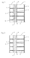
- Fig. 1 shows a clam shell masonry with air layer of an inner shell 1 and a distance set in front of outer shell 2 and a gap 3 between inner shell 1 and outer shell 2.
- the inner shell 1 is in the usual way by a masonry formed of superimposed mortared blocks 4, wherein between the blocks 4 corresponding, filled with mortar bearing joints are present, which are denoted by 5.
- the outer shell 2 is formed of masonry and indeed from one another mortared clinker bricks 6. Again, the bearing joint is denoted by 5.
- the bearing joints 5 of the inner shell 1 are designated 8 fastening anchors introduced, which are usually formed by wire anchors, such as one-piece rod-like anchor.
- wire anchors such as one-piece rod-like anchor.
- the outer shell 2 is held against the inner shell 1 and fixed.
- the wire anchors 8 fastened to the inner shell 1 extend into the bearing joints of the masonry of the outer shell 2.
- the thermal insulation here formed from an insulating panel 9 made of mineral wool.
- FIG. 1 describes a double-shell masonry with an air layer
- the outer shell 2 is set at a distance by mortaring the clinker bricks 6 one above the other.
- the corresponding joints are height aligned with each other, so that the outwardly projecting wire anchor 8 are grouted with and about the outer shell 2 is fixed relative to the inner shell 1.
- the air layer of the masonry according to FIG. 1 is denoted by 10 and serves for rear ventilation. The air flow is symbolized by an arrow.
- Fig. 2 shows a core insulation using a corresponding mineral wool plate 9, wherein in this figure the same reference numerals have been used for the same components.
- the core insulation formed from a thermal insulation panel 9 made of mineral wool fills the space between the two shells 1 and 2 completely, although for processing technical reasons in the core insulation not shown in the drawing distance of about 1 cm between the outside thermal insulation and the inside outer shell or veneer 2 is kept free, which is generally not aerated.
- the attachment of the insulation board 9 made of mineral wool merely by putting the insulation board on the previously introduced into the bearing joints of the inner shell 1 wire anchor 8, which act as Aufstecksp fauxe.
- the thermal insulation system Since the building blocks of the masonry, ie the inner shell 1 are in standard sizes, there is a uniform distance between the wire anchors of adjacent bearing joints in the stacked wire joints 8 inserted wire anchor 8 and so to speak a horizontal corridor whose height of 250 mm the standard stone size including bearing joint of the inner shell 1 corresponds.
- the mounting of the insulation boards or insulation boards is no longer by plugging on the wire anchor 8, but the insulation elements are adjusted in width B the height spacing of adjacent stacked rows of introduced into the corresponding bearing joints 5 wire anchors 8, preferably with a Oversize of 5 mm.
- the insulating elements which may be in the form of insulation boards 11 or insulation boards 12 are due to the adjusted or matched width dimension B press between the rows of stacked wire armature 8, so to speak placed in the corridors between the wire anchors and indeed introduced between the wire anchor 8 press , Due to the existing excess, the insulating elements 11, 12 fixed in this case by clamping action between the wire anchors 8 in their position and held against the inner shell 1. They only need to be inserted between the wire anchors 8 and pressed against the outer surface of the inner shell 1. Another assembly effort greater effort is unnecessary. As a result, the insulating elements 11, 12 are exactly joint-wise aligned and arranged one above the other, so that an oblique orientation or the like.
- the insulating elements 11, 12 have a width of 255 mm under inclusion of an excess of 5 mm .
- the insulation elements can be pressed between the wire anchors , are held there and form a thermal bridge-free composite also in the area of their joints.
- the outer shell 2 can then be bricked up or set in the conventional manner, with or without ventilation.
- the width of the insulating elements is aligned with the Baurichtstock, which is 12.5 cm according to DIN 4172, i. the width is an integer multiple of the construction dimension (height of stone and mortar joint). In this case, preferred widths are 125 mm, 250 mm, 375 mm, 500 mm and 625 mm. Although only one insulating element is provided between adjacent rows of wire anchors arranged on top of each other with reference to the preferred embodiment described in FIG . Per corridor also several insulating elements are arranged one above the other.
- both insulation boards 11 and insulation boards 12 can be used separately or together per object.
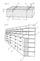
- Fig. 4 shows an insulating element in the form of a foam plate 14 made of EPS, in which recesses 16 are introduced at the upper longitudinal surface, in a longitudinal distance L to each other. That is, in this embodiment, the arrangement of the wire anchors is given by these recesses as a kind of template.
- the width BR of the recesses 16 is in this case matched to the diameter of the wire anchors and is usually in the range of 3 to 5 mm.
- the depth T of the recesses 16 corresponds at least to the diameter of the wire anchors.
- the longitudinal distance L between the recesses 16 is about 75 cm.
- Fig. 5 shows the assembled arrangement of the insulating elements and in the upper two rows of recesses 16 insulating boards 15 and provided in the lower two rows with recesses 16 insulation boards.
- the walling of the inner shell takes place simultaneously with the attachment of the insulation, wherein the wire anchors are inserted by utilizing the template function of the insulating elements in their predetermined recesses. Thereafter, the fixing of the inserted wire anchors by the bricking of the next stone layer, and at the same time serving as a template insulation elements in the form of a clamp.
- the outer shell is then in turn pre-set in a conventional manner, wherein the protruding wire anchors are embedded in the joints.
- Fig. 6 shows the embodiment of a thermal insulation system with insulating elements, which are provided with recesses 16, wherein in this embodiment, the superior outer shell 2 and the gap 3 is shown.
- the insulating material webs are conveniently kept ready in roll form and in lengths preferably from 2,000 mm to 10,000 mm.
- the strip-shaped insulation boards are preferably kept in lengths of 1,000 mm to 2,000 mm.
- the insulation boards and insulation boards can be laminated on one or both sides. As lamination is suitable, for example a glass fleece.
Priority Applications (1)
| Application Number | Priority Date | Filing Date | Title |
|---|---|---|---|
| PL05015003T PL1617001T3 (pl) | 2004-07-12 | 2005-07-11 | System izolacji cieplnej dla dwupowłokowych ścian zewnętrznych |
Applications Claiming Priority (1)
| Application Number | Priority Date | Filing Date | Title |
|---|---|---|---|
| DE102004033607A DE102004033607A1 (de) | 2004-07-12 | 2004-07-12 | Wärmedämmsystem für zweischalige Außenwände |
Publications (3)
| Publication Number | Publication Date |
|---|---|
| EP1617001A2 true EP1617001A2 (fr) | 2006-01-18 |
| EP1617001A3 EP1617001A3 (fr) | 2006-11-08 |
| EP1617001B1 EP1617001B1 (fr) | 2009-09-30 |
Family
ID=34979331
Family Applications (1)
| Application Number | Title | Priority Date | Filing Date |
|---|---|---|---|
| EP05015003A Not-in-force EP1617001B1 (fr) | 2004-07-12 | 2005-07-11 | Système d'isolation thermique pour mur extérieur à double paroi |
Country Status (5)
| Country | Link |
|---|---|
| EP (1) | EP1617001B1 (fr) |
| AT (1) | ATE444417T1 (fr) |
| DE (2) | DE102004033607A1 (fr) |
| DK (1) | DK1617001T3 (fr) |
| PL (1) | PL1617001T3 (fr) |
Cited By (4)
| Publication number | Priority date | Publication date | Assignee | Title |
|---|---|---|---|---|
| NL2001794C2 (nl) * | 2008-07-11 | 2010-01-12 | Ecotherm Beheer B V | Isolatiepaneel, een spouwmuur voorzien van dergelijke isolatiepanelen en een werkwijze voor het vervaardigen van een spouwmuur. |
| CN102071782A (zh) * | 2011-01-11 | 2011-05-25 | 泉州市奇特艺工艺制品有限公司 | 一种eps轻型建筑材料 |
| BE1018967A3 (nl) * | 2009-10-19 | 2011-12-06 | Douterloigne Nv | Werkwijze voor het isoleren van een gebouw en bouwsteen daarbij toegepast. |
| CN103206032A (zh) * | 2013-03-28 | 2013-07-17 | 苏州市世好建材新技术工程有限公司 | 小温差保温墙体 |
Families Citing this family (2)
| Publication number | Priority date | Publication date | Assignee | Title |
|---|---|---|---|---|
| DE202011005374U1 (de) | 2011-04-16 | 2011-08-02 | Wilhelm Christian Koch | Einrichtung zur Wärmedämmung eines Gebäudes mit Vakuumdämmplatten |
| CN113738070A (zh) * | 2021-10-19 | 2021-12-03 | 烟台市顺达聚氨酯有限责任公司 | 一种土建冷库缝隙处保温施工方法及保温结构 |
Citations (3)
| Publication number | Priority date | Publication date | Assignee | Title |
|---|---|---|---|---|
| GB2033448A (en) * | 1978-10-10 | 1980-05-21 | Lite Pac Ltd | Wall tie supporting insulation in cavity wall |
| FR2558865A1 (fr) * | 1984-01-30 | 1985-08-02 | Ortiz Antoine | Doublage isolant exterieur pour mur de maconnerie |
| US5755070A (en) * | 1989-08-28 | 1998-05-26 | Hohmann Enterprises, Inc. | Multi veneer anchor structural assembly and drywall construction system |
Family Cites Families (3)
| Publication number | Priority date | Publication date | Assignee | Title |
|---|---|---|---|---|
| GB2069564B (en) * | 1980-02-20 | 1983-09-28 | Catnic Components Ltd | Wall tie for retaining cavity insulating material |
| GB2111095A (en) * | 1981-08-12 | 1983-06-29 | Glasgow Steel Nail Company Lim | Wall Tie |
| US6668505B1 (en) * | 2002-09-03 | 2003-12-30 | Hohmann & Barnard, Inc. | High-span anchors and reinforcements for masonry walls |
-
2004
- 2004-07-12 DE DE102004033607A patent/DE102004033607A1/de not_active Withdrawn
-
2005
- 2005-07-11 DK DK05015003T patent/DK1617001T3/da active
- 2005-07-11 PL PL05015003T patent/PL1617001T3/pl unknown
- 2005-07-11 EP EP05015003A patent/EP1617001B1/fr not_active Not-in-force
- 2005-07-11 AT AT05015003T patent/ATE444417T1/de not_active IP Right Cessation
- 2005-07-11 DE DE502005008224T patent/DE502005008224D1/de active Active
Patent Citations (3)
| Publication number | Priority date | Publication date | Assignee | Title |
|---|---|---|---|---|
| GB2033448A (en) * | 1978-10-10 | 1980-05-21 | Lite Pac Ltd | Wall tie supporting insulation in cavity wall |
| FR2558865A1 (fr) * | 1984-01-30 | 1985-08-02 | Ortiz Antoine | Doublage isolant exterieur pour mur de maconnerie |
| US5755070A (en) * | 1989-08-28 | 1998-05-26 | Hohmann Enterprises, Inc. | Multi veneer anchor structural assembly and drywall construction system |
Cited By (6)
| Publication number | Priority date | Publication date | Assignee | Title |
|---|---|---|---|---|
| NL2001794C2 (nl) * | 2008-07-11 | 2010-01-12 | Ecotherm Beheer B V | Isolatiepaneel, een spouwmuur voorzien van dergelijke isolatiepanelen en een werkwijze voor het vervaardigen van een spouwmuur. |
| BE1018967A3 (nl) * | 2009-10-19 | 2011-12-06 | Douterloigne Nv | Werkwijze voor het isoleren van een gebouw en bouwsteen daarbij toegepast. |
| BE1019521A3 (nl) * | 2009-10-19 | 2012-08-07 | Douterloigne Nv | Werkwijze voor het isoleren van een gebouw en bouwsteen daarbij toegepast. |
| CN102071782A (zh) * | 2011-01-11 | 2011-05-25 | 泉州市奇特艺工艺制品有限公司 | 一种eps轻型建筑材料 |
| CN103206032A (zh) * | 2013-03-28 | 2013-07-17 | 苏州市世好建材新技术工程有限公司 | 小温差保温墙体 |
| CN103206032B (zh) * | 2013-03-28 | 2014-12-31 | 苏州市世好建材新技术工程有限公司 | 小温差保温墙体 |
Also Published As
| Publication number | Publication date |
|---|---|
| EP1617001A3 (fr) | 2006-11-08 |
| EP1617001B1 (fr) | 2009-09-30 |
| ATE444417T1 (de) | 2009-10-15 |
| PL1617001T3 (pl) | 2010-02-26 |
| DE502005008224D1 (de) | 2009-11-12 |
| DE102004033607A1 (de) | 2006-02-16 |
| DK1617001T3 (da) | 2009-12-21 |
Similar Documents
| Publication | Publication Date | Title |
|---|---|---|
| EP2639394B1 (fr) | Bande pour bordure de mur, entourage de fenêtre et structure de mur dotée de bandes pour bordure de mur | |
| EP1617001B1 (fr) | Système d'isolation thermique pour mur extérieur à double paroi | |
| CH696546A5 (de) | Befestigungselement und Befestigungssystem für Gebäudebekleidungen. | |
| DE10147831B4 (de) | Ständerwand | |
| DE19951105C2 (de) | Wärme- und/oder Schalldämmelement | |
| EP1707699A2 (fr) | Façade de bâtiment ventilée et calorifugée | |
| EP2960392A1 (fr) | Élément de coffrage de bordure | |
| EP2067905B1 (fr) | Elément d'habillage préfabriqué pour un mur extérieur dans la zone d'un intrados de fenêtre ou de porte | |
| AT17112U1 (de) | Wand- oder Dachbekleidungsbaueinheit, Wand- und Dachbekleidungssystem, insbesondere hinterlüftetes oder hinterlüftbares Wand- und Dachbekleidungssystem, sowie Wand, insbesondere Holzrahmenbauwand, und Dach und Verwendung der Wand- oder Dachbekleidungsbaueinheit | |
| DE202012012901U1 (de) | Randschalung | |
| EP1327732B1 (fr) | Coffrage de rive pour dalles en béton | |
| DE3214502C2 (fr) | ||
| DE7625460U1 (de) | Fertigbauelement | |
| EP2330259A2 (fr) | Elément d'habillage pour un mur extérieur | |
| EP0201757A3 (fr) | Revêtement de façades, en particulier pour la restauration de l'habitat ancien | |
| EP1918469B1 (fr) | Système de raccordement d'isolation thermique | |
| EP3091167A1 (fr) | Élément de fixation pour un cadre de fenêtre sur un plafond de bâtiment d'une construction, construction associée et procédé de fixation d'un cadre de fenêtre sur un plafond de bâtiment | |
| AT13485U1 (de) | Isolierte Gebäudefassade | |
| DE202017107471U1 (de) | Deckenrandschalungselement | |
| DE102013003796A1 (de) | System für den Brandschutz von Gebäuden | |
| EP1264943B1 (fr) | Elément de paroi, de plafond et d'isolation acoustique | |
| AT522813B1 (de) | Schalungselement | |
| AT525083B1 (de) | Bausatz für einen Attikaaufbau an einem Gebäude | |
| DE102005025517B4 (de) | Eckverband für Dämmplatten | |
| AT397400B (de) | Verbindungselement für die schichten eines mehrschichtigen mauerwerks |
Legal Events
| Date | Code | Title | Description |
|---|---|---|---|
| PUAI | Public reference made under article 153(3) epc to a published international application that has entered the european phase |
Free format text: ORIGINAL CODE: 0009012 |
|
| AK | Designated contracting states |
Kind code of ref document: A2 Designated state(s): AT BE BG CH CY CZ DE DK EE ES FI FR GB GR HU IE IS IT LI LT LU LV MC NL PL PT RO SE SI SK TR |
|
| AX | Request for extension of the european patent |
Extension state: AL BA HR MK YU |
|
| PUAL | Search report despatched |
Free format text: ORIGINAL CODE: 0009013 |
|
| AK | Designated contracting states |
Kind code of ref document: A3 Designated state(s): AT BE BG CH CY CZ DE DK EE ES FI FR GB GR HU IE IS IT LI LT LU LV MC NL PL PT RO SE SI SK TR |
|
| AX | Request for extension of the european patent |
Extension state: AL BA HR MK YU |
|
| 17P | Request for examination filed |
Effective date: 20070115 |
|
| 17Q | First examination report despatched |
Effective date: 20070219 |
|
| AKX | Designation fees paid |
Designated state(s): AT BE BG CH CY CZ DE DK EE ES FI FR GB GR HU IE IS IT LI LT LU LV MC NL PL PT RO SE SI SK TR |
|
| GRAP | Despatch of communication of intention to grant a patent |
Free format text: ORIGINAL CODE: EPIDOSNIGR1 |
|
| GRAS | Grant fee paid |
Free format text: ORIGINAL CODE: EPIDOSNIGR3 |
|
| GRAA | (expected) grant |
Free format text: ORIGINAL CODE: 0009210 |
|
| AK | Designated contracting states |
Kind code of ref document: B1 Designated state(s): AT BE BG CH CY CZ DE DK EE ES FI FR GB GR HU IE IS IT LI LT LU LV MC NL PL PT RO SE SI SK TR |
|
| REG | Reference to a national code |
Ref country code: CH Ref legal event code: EP Ref country code: GB Ref legal event code: FG4D Free format text: NOT ENGLISH |
|
| REG | Reference to a national code |
Ref country code: IE Ref legal event code: FG4D |
|
| REF | Corresponds to: |
Ref document number: 502005008224 Country of ref document: DE Date of ref document: 20091112 Kind code of ref document: P |
|
| REG | Reference to a national code |
Ref country code: DK Ref legal event code: T3 |
|
| PG25 | Lapsed in a contracting state [announced via postgrant information from national office to epo] |
Ref country code: LT Free format text: LAPSE BECAUSE OF FAILURE TO SUBMIT A TRANSLATION OF THE DESCRIPTION OR TO PAY THE FEE WITHIN THE PRESCRIBED TIME-LIMIT Effective date: 20090930 Ref country code: FI Free format text: LAPSE BECAUSE OF FAILURE TO SUBMIT A TRANSLATION OF THE DESCRIPTION OR TO PAY THE FEE WITHIN THE PRESCRIBED TIME-LIMIT Effective date: 20090930 Ref country code: SE Free format text: LAPSE BECAUSE OF FAILURE TO SUBMIT A TRANSLATION OF THE DESCRIPTION OR TO PAY THE FEE WITHIN THE PRESCRIBED TIME-LIMIT Effective date: 20090930 |
|
| LTIE | Lt: invalidation of european patent or patent extension |
Effective date: 20090930 |
|
| PG25 | Lapsed in a contracting state [announced via postgrant information from national office to epo] |
Ref country code: LV Free format text: LAPSE BECAUSE OF FAILURE TO SUBMIT A TRANSLATION OF THE DESCRIPTION OR TO PAY THE FEE WITHIN THE PRESCRIBED TIME-LIMIT Effective date: 20090930 Ref country code: SI Free format text: LAPSE BECAUSE OF FAILURE TO SUBMIT A TRANSLATION OF THE DESCRIPTION OR TO PAY THE FEE WITHIN THE PRESCRIBED TIME-LIMIT Effective date: 20090930 |
|
| REG | Reference to a national code |
Ref country code: PL Ref legal event code: T3 |
|
| PG25 | Lapsed in a contracting state [announced via postgrant information from national office to epo] |
Ref country code: PT Free format text: LAPSE BECAUSE OF FAILURE TO SUBMIT A TRANSLATION OF THE DESCRIPTION OR TO PAY THE FEE WITHIN THE PRESCRIBED TIME-LIMIT Effective date: 20100201 Ref country code: IS Free format text: LAPSE BECAUSE OF FAILURE TO SUBMIT A TRANSLATION OF THE DESCRIPTION OR TO PAY THE FEE WITHIN THE PRESCRIBED TIME-LIMIT Effective date: 20100130 Ref country code: ES Free format text: LAPSE BECAUSE OF FAILURE TO SUBMIT A TRANSLATION OF THE DESCRIPTION OR TO PAY THE FEE WITHIN THE PRESCRIBED TIME-LIMIT Effective date: 20100110 Ref country code: EE Free format text: LAPSE BECAUSE OF FAILURE TO SUBMIT A TRANSLATION OF THE DESCRIPTION OR TO PAY THE FEE WITHIN THE PRESCRIBED TIME-LIMIT Effective date: 20090930 Ref country code: CZ Free format text: LAPSE BECAUSE OF FAILURE TO SUBMIT A TRANSLATION OF THE DESCRIPTION OR TO PAY THE FEE WITHIN THE PRESCRIBED TIME-LIMIT Effective date: 20090930 Ref country code: RO Free format text: LAPSE BECAUSE OF FAILURE TO SUBMIT A TRANSLATION OF THE DESCRIPTION OR TO PAY THE FEE WITHIN THE PRESCRIBED TIME-LIMIT Effective date: 20090930 |
|
| PG25 | Lapsed in a contracting state [announced via postgrant information from national office to epo] |
Ref country code: SK Free format text: LAPSE BECAUSE OF FAILURE TO SUBMIT A TRANSLATION OF THE DESCRIPTION OR TO PAY THE FEE WITHIN THE PRESCRIBED TIME-LIMIT Effective date: 20090930 Ref country code: CY Free format text: LAPSE BECAUSE OF FAILURE TO SUBMIT A TRANSLATION OF THE DESCRIPTION OR TO PAY THE FEE WITHIN THE PRESCRIBED TIME-LIMIT Effective date: 20090930 |
|
| PLBE | No opposition filed within time limit |
Free format text: ORIGINAL CODE: 0009261 |
|
| STAA | Information on the status of an ep patent application or granted ep patent |
Free format text: STATUS: NO OPPOSITION FILED WITHIN TIME LIMIT |
|
| 26N | No opposition filed |
Effective date: 20100701 |
|
| PG25 | Lapsed in a contracting state [announced via postgrant information from national office to epo] |
Ref country code: GR Free format text: LAPSE BECAUSE OF FAILURE TO SUBMIT A TRANSLATION OF THE DESCRIPTION OR TO PAY THE FEE WITHIN THE PRESCRIBED TIME-LIMIT Effective date: 20091231 |
|
| PG25 | Lapsed in a contracting state [announced via postgrant information from national office to epo] |
Ref country code: MC Free format text: LAPSE BECAUSE OF NON-PAYMENT OF DUE FEES Effective date: 20100731 |
|
| REG | Reference to a national code |
Ref country code: CH Ref legal event code: PL |
|
| PG25 | Lapsed in a contracting state [announced via postgrant information from national office to epo] |
Ref country code: IT Free format text: LAPSE BECAUSE OF FAILURE TO SUBMIT A TRANSLATION OF THE DESCRIPTION OR TO PAY THE FEE WITHIN THE PRESCRIBED TIME-LIMIT Effective date: 20090930 |
|
| REG | Reference to a national code |
Ref country code: FR Ref legal event code: ST Effective date: 20110331 |
|
| PG25 | Lapsed in a contracting state [announced via postgrant information from national office to epo] |
Ref country code: CH Free format text: LAPSE BECAUSE OF NON-PAYMENT OF DUE FEES Effective date: 20100731 Ref country code: LI Free format text: LAPSE BECAUSE OF NON-PAYMENT OF DUE FEES Effective date: 20100731 |
|
| PG25 | Lapsed in a contracting state [announced via postgrant information from national office to epo] |
Ref country code: FR Free format text: LAPSE BECAUSE OF NON-PAYMENT OF DUE FEES Effective date: 20100802 |
|
| PG25 | Lapsed in a contracting state [announced via postgrant information from national office to epo] |
Ref country code: AT Free format text: LAPSE BECAUSE OF NON-PAYMENT OF DUE FEES Effective date: 20100711 |
|
| PG25 | Lapsed in a contracting state [announced via postgrant information from national office to epo] |
Ref country code: HU Free format text: LAPSE BECAUSE OF FAILURE TO SUBMIT A TRANSLATION OF THE DESCRIPTION OR TO PAY THE FEE WITHIN THE PRESCRIBED TIME-LIMIT Effective date: 20100401 Ref country code: LU Free format text: LAPSE BECAUSE OF NON-PAYMENT OF DUE FEES Effective date: 20100711 Ref country code: BG Free format text: LAPSE BECAUSE OF FAILURE TO SUBMIT A TRANSLATION OF THE DESCRIPTION OR TO PAY THE FEE WITHIN THE PRESCRIBED TIME-LIMIT Effective date: 20090930 |
|
| PG25 | Lapsed in a contracting state [announced via postgrant information from national office to epo] |
Ref country code: TR Free format text: LAPSE BECAUSE OF FAILURE TO SUBMIT A TRANSLATION OF THE DESCRIPTION OR TO PAY THE FEE WITHIN THE PRESCRIBED TIME-LIMIT Effective date: 20090930 |
|
| PGFP | Annual fee paid to national office [announced via postgrant information from national office to epo] |
Ref country code: DK Payment date: 20130722 Year of fee payment: 9 Ref country code: BE Payment date: 20130725 Year of fee payment: 9 Ref country code: NL Payment date: 20130725 Year of fee payment: 9 Ref country code: IE Payment date: 20130727 Year of fee payment: 9 |
|
| PGFP | Annual fee paid to national office [announced via postgrant information from national office to epo] |
Ref country code: GB Payment date: 20130724 Year of fee payment: 9 |
|
| PGFP | Annual fee paid to national office [announced via postgrant information from national office to epo] |
Ref country code: PL Payment date: 20140630 Year of fee payment: 10 |
|
| REG | Reference to a national code |
Ref country code: DK Ref legal event code: EBP Effective date: 20140731 |
|
| REG | Reference to a national code |
Ref country code: NL Ref legal event code: V1 Effective date: 20150201 |
|
| GBPC | Gb: european patent ceased through non-payment of renewal fee |
Effective date: 20140711 |
|
| PG25 | Lapsed in a contracting state [announced via postgrant information from national office to epo] |
Ref country code: NL Free format text: LAPSE BECAUSE OF NON-PAYMENT OF DUE FEES Effective date: 20150201 |
|
| REG | Reference to a national code |
Ref country code: IE Ref legal event code: MM4A |
|
| PG25 | Lapsed in a contracting state [announced via postgrant information from national office to epo] |
Ref country code: GB Free format text: LAPSE BECAUSE OF NON-PAYMENT OF DUE FEES Effective date: 20140711 |
|
| PG25 | Lapsed in a contracting state [announced via postgrant information from national office to epo] |
Ref country code: DK Free format text: LAPSE BECAUSE OF NON-PAYMENT OF DUE FEES Effective date: 20140731 |
|
| PG25 | Lapsed in a contracting state [announced via postgrant information from national office to epo] |
Ref country code: IE Free format text: LAPSE BECAUSE OF NON-PAYMENT OF DUE FEES Effective date: 20140711 |
|
| PG25 | Lapsed in a contracting state [announced via postgrant information from national office to epo] |
Ref country code: PL Free format text: LAPSE BECAUSE OF NON-PAYMENT OF DUE FEES Effective date: 20150711 |
|
| PG25 | Lapsed in a contracting state [announced via postgrant information from national office to epo] |
Ref country code: BE Free format text: LAPSE BECAUSE OF NON-PAYMENT OF DUE FEES Effective date: 20140731 |
|
| PGFP | Annual fee paid to national office [announced via postgrant information from national office to epo] |
Ref country code: DE Payment date: 20220531 Year of fee payment: 18 |
|
| REG | Reference to a national code |
Ref country code: DE Ref legal event code: R119 Ref document number: 502005008224 Country of ref document: DE |
|
| PG25 | Lapsed in a contracting state [announced via postgrant information from national office to epo] |
Ref country code: DE Free format text: LAPSE BECAUSE OF NON-PAYMENT OF DUE FEES Effective date: 20240201 |